Installation and Quick Start - · PDF fileAutomatic Transfer Switch Installation and Quick...
24
Installation and Quick Start Automatic Transfer Switch
Transcript of Installation and Quick Start - · PDF fileAutomatic Transfer Switch Installation and Quick...

Installation andQuick Start
Automatic TransferSwitch
This manual is available in English on the APC Web site (www.apc.com).
Dieses Handbuch ist in Deutsch auf der APC Webseite (www.apc.com) verfügbar.
Este manual está disponible en español en la página web de APC (www.apc.com).
Ce manuel est disponible en français sur le site internet d’APC (www.apc.com).
Questo manuale è disponibile in italiano sul sito web di APC (www.apc.com).
Instrukcja obsługi w języku polskim jest dostępna na stronie internetowej APC (www.apc.com).
Данное руководство на русском языке доступно на сайте APC (www.apc.com )
本マニュアルの日本語版はAPCウェブサイト(www.apc.com)からダウン
ロードできます。在 APC 公司的网站上 (www.apc.com) 有本手册的中文版。
Contents
Preliminary Information . . . . . . . . . . . . . . . . . . . . . . . . . . . . . . . . . . . .1
Additional documentation . . . . . . . . . . . . . . . . . . . . . . . . . . . . . . . . . . 1
Please recycle . . . . . . . . . . . . . . . . . . . . . . . . . . . . . . . . . . . . . . . . . . . 1
Receiving inspection . . . . . . . . . . . . . . . . . . . . . . . . . . . . . . . . . . . . . . 1
Product inventory . . . . . . . . . . . . . . . . . . . . . . . . . . . . . . . . . . . . . . . . 1
Overview. . . . . . . . . . . . . . . . . . . . . . . . . . . . . . . . . . . . . . . . . . . . . . . . .2
Front panel . . . . . . . . . . . . . . . . . . . . . . . . . . . . . . . . . . . . . . . . . . . . . . 2
Installation . . . . . . . . . . . . . . . . . . . . . . . . . . . . . . . . . . . . . . . . . . . . . . .3
Attach mounting brackets . . . . . . . . . . . . . . . . . . . . . . . . . . . . . . . . . . 3
Disassemble the adjustable brackets . . . . . . . . . . . . . . . . . . . . . . . . 3
Attach rear segments to the rack . . . . . . . . . . . . . . . . . . . . . . . . . . . . 4
Attach front segments to the switch . . . . . . . . . . . . . . . . . . . . . . . . . 4
Mount the Automatic Transfer Switch in the enclosure . . . . . . . . . . 5
Quick Configuration . . . . . . . . . . . . . . . . . . . . . . . . . . . . . . . . . . . . . . .6
Overview . . . . . . . . . . . . . . . . . . . . . . . . . . . . . . . . . . . . . . . . . . . . . . . . 6
TCP/IP configuration methods . . . . . . . . . . . . . . . . . . . . . . . . . . . . . . 6
Device IP Configuration Wizard . . . . . . . . . . . . . . . . . . . . . . . . . . . . . 7
BOOTP & DHCP configuration . . . . . . . . . . . . . . . . . . . . . . . . . . . . . . 7
The Automatic Transfer Switch Interfaces . . . . . . . . . . . . . . . . . . . .10
Overview . . . . . . . . . . . . . . . . . . . . . . . . . . . . . . . . . . . . . . . . . . . . . . . 10
Web interface . . . . . . . . . . . . . . . . . . . . . . . . . . . . . . . . . . . . . . . . . . . 10
Telnet/SSH . . . . . . . . . . . . . . . . . . . . . . . . . . . . . . . . . . . . . . . . . . . . . 11
SNMP . . . . . . . . . . . . . . . . . . . . . . . . . . . . . . . . . . . . . . . . . . . . . . . . . . 11
FTP/SCP . . . . . . . . . . . . . . . . . . . . . . . . . . . . . . . . . . . . . . . . . . . . . . . 12
Local access to the control console . . . . . . . . . . . . . . . . . . . . . . . . 12
Remote access to the control console . . . . . . . . . . . . . . . . . . . . . . 13
Configuring the ATS . . . . . . . . . . . . . . . . . . . . . . . . . . . . . . . . . . . . . .14
Configuring sensitivity . . . . . . . . . . . . . . . . . . . . . . . . . . . . . . . . . . . 14
Configuring voltage transfer range . . . . . . . . . . . . . . . . . . . . . . . . . 14
Recovering From A Lost Password. . . . . . . . . . . . . . . . . . . . . . . . . .15
Automatic Transfer Switch Installation and Quick Start i

Two-Year Factory Warranty . . . . . . . . . . . . . . . . . . . . . . . . . . . . . . . . 16
Terms of warranty . . . . . . . . . . . . . . . . . . . . . . . . . . . . . . . . . . . . . . . 16
Non-transferable warranty . . . . . . . . . . . . . . . . . . . . . . . . . . . . . . . . 16
Exclusions . . . . . . . . . . . . . . . . . . . . . . . . . . . . . . . . . . . . . . . . . . . . . 16
Warranty claims . . . . . . . . . . . . . . . . . . . . . . . . . . . . . . . . . . . . . . . . . 17
USA—FCC . . . . . . . . . . . . . . . . . . . . . . . . . . . . . . . . . . . . . . . . . . . . . 18
Canada—ICES . . . . . . . . . . . . . . . . . . . . . . . . . . . . . . . . . . . . . . . . . . 18
Japan—VCCI . . . . . . . . . . . . . . . . . . . . . . . . . . . . . . . . . . . . . . . . . . . 18
ii Automatic Transfer Switch Installation and Quick Start
Preliminary InformationAdditional documentation
This Installation and Quick Start Manual and the online User’s Guide are available on the supplied CD or on the American Power Conversion (APC®) Web site www.apc.com. The online User Guide contains additional information about the following topics related to the Automatic Transfer Switch:
• Management interfaces
• User accounts
• Customizing setup
• Security
Please recycle
The shipping materials are recyclable. Please save them for later use, or dispose of them appropriately.
Receiving inspection
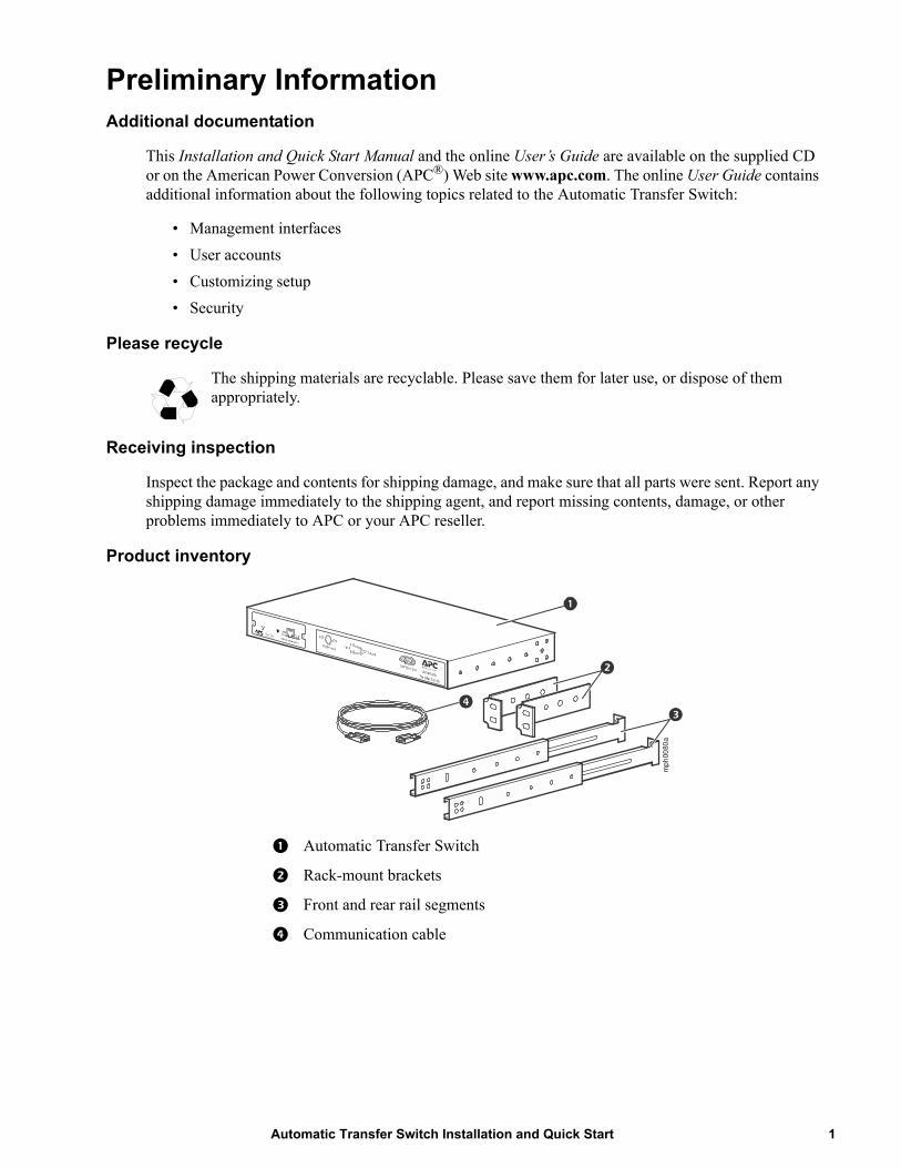
Inspect the package and contents for shipping damage, and make sure that all parts were sent. Report any shipping damage immediately to the shipping agent, and report missing contents, damage, or other problems immediately to APC or your APC reseller.
Product inventory
Automatic Transfer Switch
Rack-mount brackets
Front and rear rail segments
Communication cable
mp
h00
80a
1Automatic Transfer Switch Installation and Quick Start
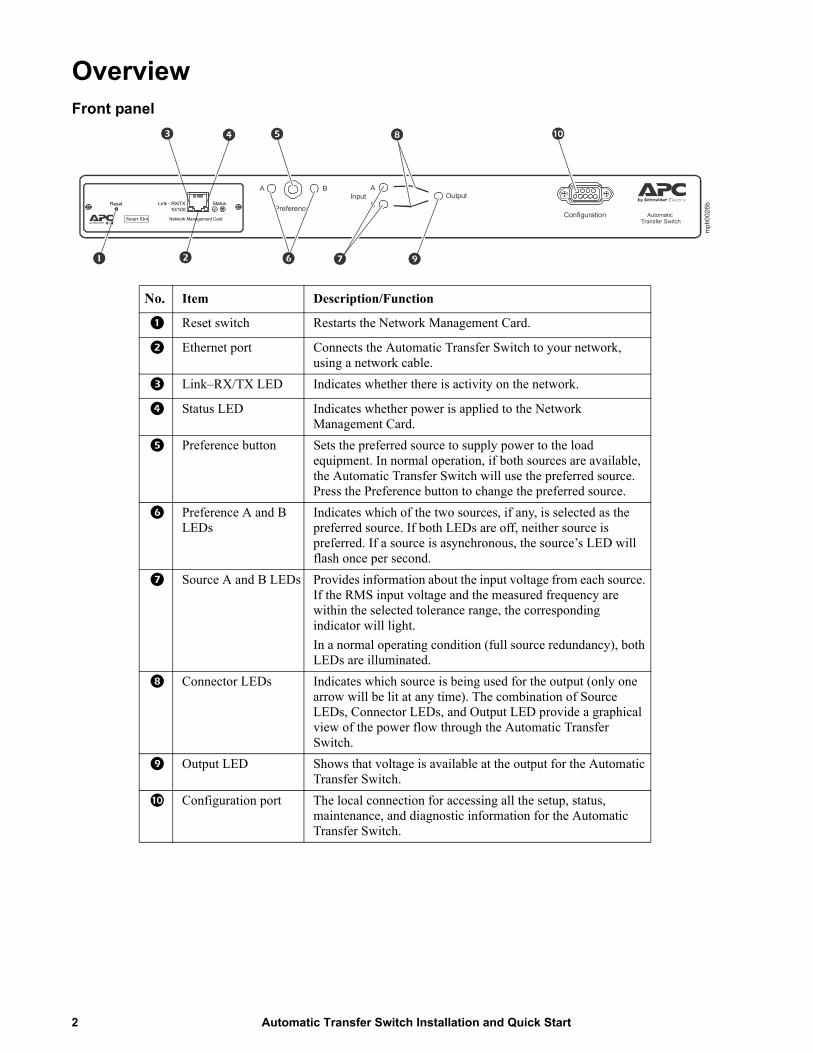
OverviewFront panel
No. Item Description/Function
Reset switch Restarts the Network Management Card.
Ethernet port Connects the Automatic Transfer Switch to your network, using a network cable.
Link–RX/TX LED Indicates whether there is activity on the network.
Status LED Indicates whether power is applied to the Network Management Card.
Preference button Sets the preferred source to supply power to the load equipment. In normal operation, if both sources are available, the Automatic Transfer Switch will use the preferred source. Press the Preference button to change the preferred source.
Preference A and B LEDs
Indicates which of the two sources, if any, is selected as the preferred source. If both LEDs are off, neither source is preferred. If a source is asynchronous, the source’s LED will flash once per second.
Source A and B LEDs Provides information about the input voltage from each source. If the RMS input voltage and the measured frequency are within the selected tolerance range, the corresponding indicator will light.
In a normal operating condition (full source redundancy), both LEDs are illuminated.
Connector LEDs Indicates which source is being used for the output (only one arrow will be lit at any time). The combination of Source LEDs, Connector LEDs, and Output LED provide a graphical view of the power flow through the Automatic Transfer Switch.
Output LED Shows that voltage is available at the output for the Automatic Transfer Switch.
Configuration port The local connection for accessing all the setup, status, maintenance, and diagnostic information for the Automatic Transfer Switch.
Configuration
A
BOutputInput
Preference
A B
Automatic Transfer Switch
mp
h002
6bReset Link - RX/TX Status
10/100
Smart Slot Network Management Card
Automatic Transfer Switch Installation and Quick Start2
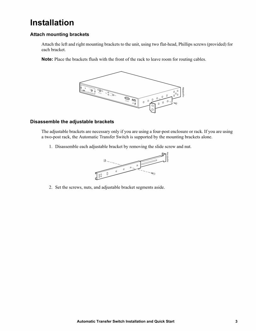
InstallationAttach mounting brackets
Attach the left and right mounting brackets to the unit, using two flat-head, Phillips screws (provided) for each bracket.
Note: Place the brackets flush with the front of the rack to leave room for routing cables.
Disassemble the adjustable brackets
The adjustable brackets are necessary only if you are using a four-post enclosure or rack. If you are using a two-post rack, the Automatic Transfer Switch is supported by the mounting brackets alone.
1. Disassemble each adjustable bracket by removing the slide screw and nut.
2. Set the screws, nuts, and adjustable bracket segments aside.m
ph00
96a
mp
h00
14a
3Automatic Transfer Switch Installation and Quick Start
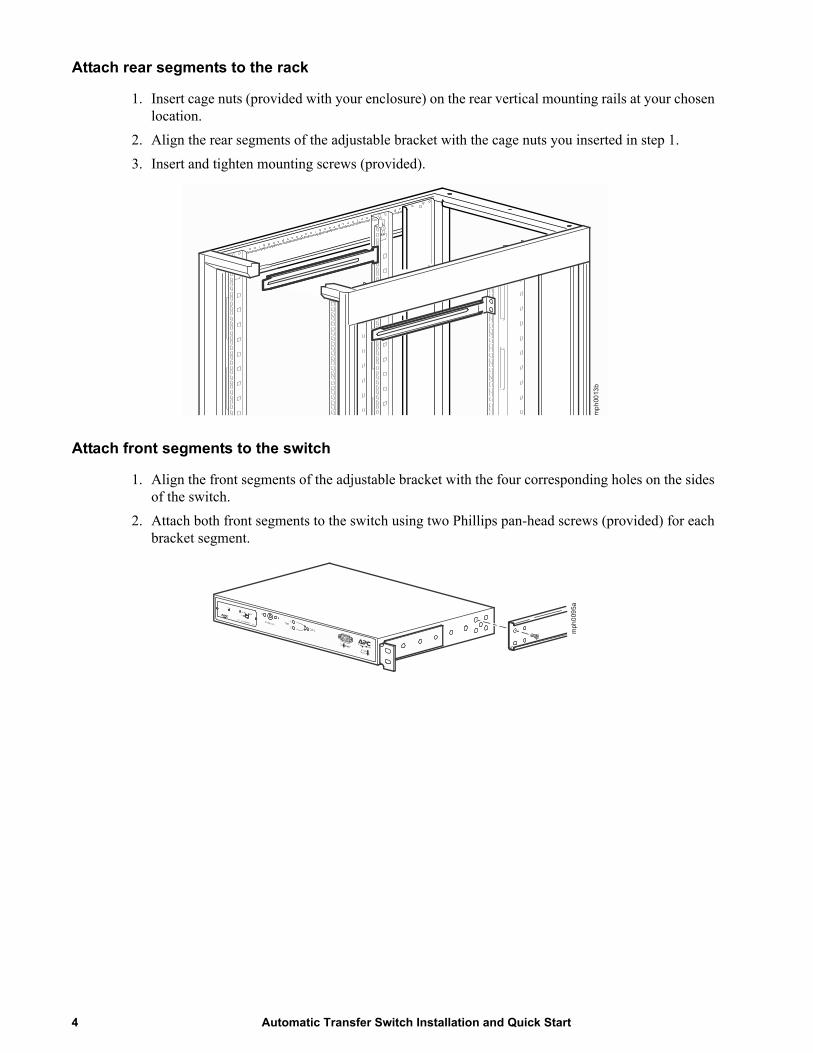
Attach rear segments to the rack
1. Insert cage nuts (provided with your enclosure) on the rear vertical mounting rails at your chosen location.
2. Align the rear segments of the adjustable bracket with the cage nuts you inserted in step 1.
3. Insert and tighten mounting screws (provided).
Attach front segments to the switch
1. Align the front segments of the adjustable bracket with the four corresponding holes on the sides of the switch.
2. Attach both front segments to the switch using two Phillips pan-head screws (provided) for each bracket segment.
mp
h00
13b
mph
009
5a
Automatic Transfer Switch Installation and Quick Start4
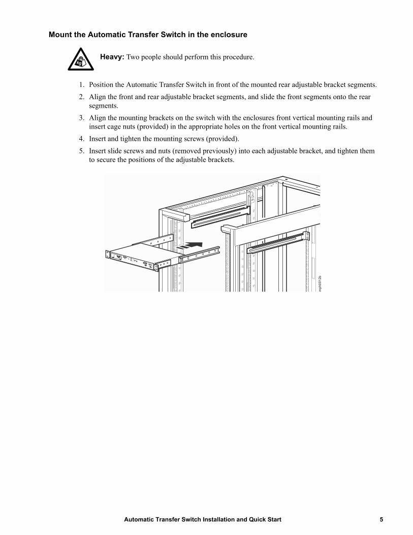
Mount the Automatic Transfer Switch in the enclosure
Heavy: Two people should perform this procedure.
1. Position the Automatic Transfer Switch in front of the mounted rear adjustable bracket segments.
2. Align the front and rear adjustable bracket segments, and slide the front segments onto the rear segments.
3. Align the mounting brackets on the switch with the enclosures front vertical mounting rails and insert cage nuts (provided) in the appropriate holes on the front vertical mounting rails.
4. Insert and tighten the mounting screws (provided).
5. Insert slide screws and nuts (removed previously) into each adjustable bracket, and tighten them to secure the positions of the adjustable brackets.
mp
h001
2b
5Automatic Transfer Switch Installation and Quick Start

Quick ConfigurationNote: Disregard the procedures in this section if you have StruxureWare as part of your system. See the StruxureWare documentation for more information.
Overview
You must configure the following TCP/IP settings before the Automatic Transfer Switch can operate on a network:
• IP address of the Automatic Transfer Switch
• Subnet mask
• Default gateway
Note: If a default gateway is unavailable, use the IP address of a computer that is located on the same subnet as the Automatic Transfer Switch and that is usually running. The Automatic Transfer Switch uses the default gateway to test the network when traffic is very light. See “Watchdog Features” in the “Introduction” of the Automatic Transfer Switch User’s Guide for more information about the watchdog role of the default gateway.
TCP/IP configuration methods
Use one of the following methods to define the TCP/IP settings needed by the Automatic Transfer Switch:
• Device IP Configuration Wizard (See “Device IP Configuration Wizard” on page 7.)
• BOOTP or DHCP server (See “BOOTP & DHCP configuration” on page 7.)
• Local computer (See “Local access to the control console” on page 12.)
• Networked computer (See “Remote access to the control console” on page 13.)
Automatic Transfer Switch Installation and Quick Start6
Device IP Configuration Wizard
You can use the Device IP Configuration Wizard on a Windows NT® 4.0, Windows 2000®, Windows 2003, or Windows XP computer to discover unconfigured Automatic Transfer Switches and configure their basic TCP/IP settings.
To configure one or more Automatic Transfer Switches by exporting configuration settings from a configured Automatic Transfer Switch, see “How to Export Configuration Settings” in the User’s Guide on the Utility CD.
1. Insert the APC Automatic Transfer Switch Utility CD into a computer on your network.
2. Select the Device IP Configuration Wizard from the main menu.
3. Wait for the Wizard to discover the first unconfigured Automatic Transfer Switch, then follow the on-screen instructions. Note: If you leave the Start a Web browser when finished option enabled, you can use apc for both the User Name and Password to access the Automatic Transfer Switch through your browser.
BOOTP & DHCP configuration
The Boot Mode Setting, a TCP/IP option in the Automatic Transfer Switches Network menu, identifies how the TCP/IP settings will be defined. The possible settings are Manual, DHCP only, BOOTP only, and DHCP & BOOTP (the default setting).
Note: The DHCP & BOOTP setting assumes that a properly configured DHCP or BOOTP server is available to provide TCP/IP settings to Automatic Transfer Switches.
If these servers are unavailable, see:
“Device IP Configuration Wizard” on this page. “Local access to the control console” on page 12. “Remote access to the control console” on page 13.
With Boot Mode set to DHCP & BOOTP, the Automatic Transfer Switch attempts to discover a properly configured server. It first searches for a BOOTP server, then a DHCP server, and repeats this pattern until it discovers a BOOTP or DHCP server. For more information, see “BOOTP” on page 8 or “DHCP” on page 8.
7Automatic Transfer Switch Installation and Quick Start

BOOTP. You can use an RFC951-compliant BOOTP server to configure the TCP/IP settings for the Automatic Transfer Switch.
Note: The DHCP & BOOTP setting assumes that a properly configured DHCP or BOOTP server is available to provide TCP/IP settings to Automatic Transfer Switches.
1. Enter the Automatic Transfer Switches MAC and IP addresses, the subnet mask and default gateway settings, and an optional Bootup file name in the BOOTPTAB file of the BOOTP server. For the MAC address, look on the bottom of the Automatic Transfer Switch or on the Quality Assurance slip included in the package.
2. When the Automatic Transfer Switch reboots, the BOOTP server provides it with the TCP/IP settings.
– If you specified a bootup file name, the Automatic Transfer Switch attempts to transfer that file from the BOOTP server using TFTP or FTP. The Automatic Transfer Switch assumes all settings specified in the bootup file. To create the bootup file, see your BOOTP server documentation.
– If you did not specify a bootup file name, the Automatic Transfer Switch can be configured remotely by using Telnet or by using the Web interface: User Name and Password are both apc, by default.
DHCP. You can use a RFC2131/RFC2132-compliant DHCP server to configure the TCP/IP settings for the Automatic Transfer Switch. This section briefly summarizes the Automatic Transfer Switch communication with a DHCP server. For more detail about how a DHCP server is used to configure the network settings for an Automatic Transfer Switch, see “DHCP Configuration” in the Automatic Transfer Switch User’s Guide.
1. An Automatic Transfer Switch sends out a DHCP request that uses the following to identify itself:
– A Vendor Class Identifier (APC by default)
– A Client Identifier (by default, the Automatic Transfer Switches MAC address value)
– A User Class Identifier (by default, the identification of the Automatic Transfer Switches application firmware)
Automatic Transfer Switch Installation and Quick Start8

2. A properly configured DHCP server responds with a DHCP offer that includes all of the settings that the Automatic Transfer Switch needs for network communication. The DHCP offer also includes the Vendor Specific Information option (DHCP option 43). By default, the Automatic Transfer Switch will ignore DHCP offers that do not encapsulate the APC cookie in the Vendor Specific Information option using the following hexidecimal format:
Option 43 = 01 04 31 41 50 43
where
– the first byte (01) is the code
– the second byte (04) is the length
– the remaining bytes (31 41 50 43) are the APC cookies
See your DHCP server documentation to add code to the Vendor Specific Information option. To disable the APC cookie requirement or to change the control console DHCP Cookie Is setting, use the Advanced option in the TCP/IP menu. See “Remote access to the control console” on page 13.
9Automatic Transfer Switch Installation and Quick Start

The Automatic Transfer Switch InterfacesOverview
After the Automatic Transfer Switch is running on your network, you can use the interfaces summarized here to access the unit. For more information on the interfaces, see the User Guide online at www.apc.com.
Web interface
As your browser, you can use Microsoft® Internet Explorer 5.0 (and higher) or Netscape® 6.x to access the Network Management Card through its Web interface. Other commonly available browsers also may work but have not been fully tested by APC.
To use the Web browser to configure the Automatic Transfer Switch options or to view the event log, you can use either of the following:
• The HTTP protocol (enabled by default), which provides authentication by user name and password but no encryption.
• The more secure HTTPS protocol, which provides extra security through Secure Sockets Layer (SSL) and encrypts user names, passwords, and data being transmitted. It also provides authentication of Network Management Cards by means of digital certificates.
To access the Web interface and configure the security of your device on the network:
1. Address the Network Management Card by its IP address or DNS name (if configured).
2. Enter the user name and password (by default, apc and apc for an Administrator, or device and apc for a Device Manager).
3. Select and configure the type of security you want. (This option is available only for Administrators.) See the chapter entitled “Security” in the User Guide for information on choosing and setting up your network security. Use the Web/SSL option of the Network menu to enable or disable the HTTP or HTTPS protocols.
Automatic Transfer Switch Installation and Quick Start10

Telnet/SSH
You can access the control console through Telnet or Secure SHell (SSH), depending on which is enabled. (An Administrator can enable these access methods through the Telnet/SSH option of the Network menu.) By default, Telnet is enabled. Enabling SSH automatically disables Telnet.
Telnet for basic access. Telnet provides the basic security of authentication by user name and password, but not the high-security benefits of encryption. To use Telnet to access an Automatic Transfer Switches control console from any computer on the same subnet:
1. At a command prompt, use the following command line, and press ENTER:
telnet address
As address, use the Network Management Card IP address or DNS name (if configured).
2. Enter the user name and password (by default, apc and apc for an Administrator, or device and apc for a Device Manager).
SSH for high-security access. If you use the high security of SSL for the Web interface, use Secure SHell (SSH) for access to the control console. SSH encrypts user names, passwords, and transmitted data.
The interface, user accounts, and user access rights are the same whether you access the control console through SSH or Telnet, but to use SSH, you must first configure SSH and have an SSH client program installed on your computer. See the User Guide online for more information on configuring and using SSH.
SNMP
After you add the PowerNet MIB to a standard SNMP MIB browser, you can use that browser for SNMP access to the Automatic Transfer Switch. The default read community name is public; the default read/write community name is private.
Note: If you enable SSL and SSH for their high-security authentication and encryption, disable SNMP. Allowing SNMP access to the Automatic Transfer Switch compromises the high security you implement by choosing SSL and SSH. To disable SNMP, you must be an Administrator; use the SNMP option of the Network menu.
11Automatic Transfer Switch Installation and Quick Start

FTP/SCP
You can use FTP (enabled by default) or Secure CoPy (SCP) to transfer new firmware to the Automatic Transfer Switch, or to access a copy of the Automatic Transfer Switches event logs. SCP provides the higher security of encrypted data transmission and is enabled automatically when you enable SSH.
Note: If you enable SSL and SSH for their high-security authentication and encryption, disable FTP. Allowing file transfer to the Automatic Transfer Switch through FTP compromises the high security you implement by choosing SSL and SSH. To disable FTP, you must be an Administrator; use the FTP Server option of the Network menu.
To access the Automatic Transfer Switch through FTP or SCP, the default user name and password are apc and apc for an Administrator, or device and apc for a Device Manager. In the command line, use the IP address of the unit. See the User Guide to use FTP or SCP to transfer firmware files to the Network Management Card or to retrieve log files from the Network Management Card.
Local access to the control console
1. Select a serial port at the local computer and disable any service that uses that port.
2. Connect APC serial cable 940-1000B to the Automatic Transfer Switch serial port and to the serial port on the local computer. Run a terminal program (such as Windows HyperTerminal®) and configure the selected port for 19200 bps, 8 data bits, no parity, 1 stop bit, and no flow control, and save the changes.
3. Press ENTER and log on as the Automatic Transfer Switch administrator. Select option 11, Web config, from the main menu and then disconnect the terminal program.
4. Reconfigure the selected port for 2400 bps, 8 data bits, no parity, 1 stop bit, and no flow control, and reconnect HyperTerminal.
5. Press ENTER to display the User Name prompt.
Note: The Automatic Transfer Switch AP7701 and AP7722 is not configurable through a terminal program. Use other options available for configuring the unit:
See “BOOTP & DHCP configuration” on page 7 for configuration using BOOTP and DHCP.
ARP can be used if an APC SmartSlot enabled UPS is available. Install the Network Management Card to the UPS and configure the IP settings. Install the configured Network Management Card in the Automatic Transfer Switch.
If an APC Expansion or Triple Chassis is available install the Network Management Card and connect the chassis to a local computer or server. Configure the card using a terminal program. Install the configured Network Management Card in the Automatic Transfer Switch.
Automatic Transfer Switch Installation and Quick Start12

Remote access to the control console
From any computer on the same subnet as the Automatic Transfer Switch, you can use ARP and Ping to assign an IP address to a Automatic Transfer Switch, and then use Telnet to access that Automatic Transfer Switches control console and configure the needed TCP/IP settings.
Note: After the Automatic Transfer Switch has its IP address configured, you can use Telnet, without first using ARP and Ping, to access that Automatic Transfer Switch.
Use ARP to define an IP address for the Automatic Transfer Switch, and use the Automatic Transfer Switches MAC address in the ARP command. For example, to define an IP address of 156.205.14.141 for a Automatic Transfer Switch that has a MAC address of 00 c0 b7 63 9f 67, use one of the following commands:
– Windows command format:
arp -s 156.205.14.141 00-c0-b7-63-9f-67
– LINUX command format:
arp -s 156.205.14.141 00:c0:b7:63:9f:67
13Automatic Transfer Switch Installation and Quick Start

Configuring the ATSConfiguring sensitivity
The sensitivity setting controls how tolerant the ATS is of fluctuations in power before it switches to the secondary power source. Configure the sensitivity range for your ATS using the Switch Configuration menu. When sensitivity is set to low, the ATS will wait 5 ms before switching to the alternate power source when there is a disturbance in the power supply. When sensitivity is set to high, the ATS will wait 3 ms before transferring power. The default setting is high.
Configuring voltage transfer range
The voltage transfer range determines the acceptable RMS voltages for the ATS. When voltage moves outside the specified range, the ATS switches to the secondary power source. Configure the voltage transfer range using the Switch Configuration menu. The ATS can be set to narrow, medium, or wide voltage ranges depending on the power conditions of your system. Note: The default setting of the voltage range is Medium.
APC Part Number Nominal Voltage (L–N)
Narrow Medium Wide
AP7701 120 V 20 (110–130 V) 23 (108.5–131.5 V) 27 (106.5–133.5 V)
AP7722 230 V 30 (215–245 V) 35 (212.5–247.5 V) 40 (210–250 V)
AP7750 120 V 20 (110–130 V) 23 (108.5–131.5 V) 27 (106.5–133.5 V)
NOTICEUNSUPPORTED APPLICATION: AP7701 must be connected to sources that are in-phase. Out-of-phase switching is not supported. Equipment damage may result.
Automatic Transfer Switch Installation and Quick Start14

Recovering From A Lost PasswordNote: Use the following instructions to reset the Network Management Card password.
1. Select a serial port at the local computer and disable any service that uses that port.
2. Connect APC serial cable 940-1000B to the Automatic Transfer Switch serial port and to the serial port on the local computer. Run a terminal program (such as Windows HyperTerminal) and configure the selected port for 19200 bps, 8 data bits, no parity, 1 stop bit, and no flow control, and save the changes.
3. Press ENTER and log on as the Automatic Transfer Switch administrator. Select option 11, Web config from the main menu and then disconnect the terminal program.
4. Reconfigure the selected port for 2400 bps, 8 data bits, no parity, 1 stop bit, and no flow control, and reconnect HyperTerminal.
5. Press ENTER to display the User Name prompt.
6. Press the RESET button on the Network Management Card, which causes the Network Management Card to restart, a process that typically takes approximately 15 seconds.
7. Press ENTER as many times as necessary to re-display the User Name prompt, then use apc for the user name and password. (If you take longer than 30 seconds to log on after the User Name prompt is redisplayed, you must start the login procedure again at step 5.)
8. From the Control Console menu, select System, then User Manager.
9. Select Administrator, and change the User Name and Password settings, both of which were originally defined as apc.
10.Press CTRL-C and log off. You must perform the entire procedure (log on, change the user name and password, and log off) within two minutes so that you are not logged off for inactivity. If you are logged off automatically, the new settings will not take effect and you must repeat the entire procedure from the beginning.
11. Press and hold down the Preference button on the Automatic Transfer Switch, which causes the Automatic Transfer Switch to reset, typically in 10 to 15 seconds.
12.Reconfigure the selected port for 19200 bps, 8 data bits, no parity, 1 stop bit, and no flow control, and reconnect HyperTerminal.
15Automatic Transfer Switch Installation and Quick Start
Two-Year Factory WarrantyThis warranty applies only to the products you purchase for your use in accordance with this manual.
Terms of warranty
APC warrants its products to be free from defects in materials and workmanship for a period of two years from the date of purchase. APC will repair or replace defective products covered by this warranty. This warranty does not apply to equipment that has been damaged by accident, negligence or misapplication or has been altered or modified in any way. Repair or replacement of a defective product or part thereof does not extend the original warranty period. Any parts furnished under this warranty may be new or factory-remanufactured.
Non-transferable warranty
This warranty extends only to the original purchaser who must have properly registered the product. The product may be registered at the APC Web site, www.apc.com.
Exclusions
APC shall not be liable under the warranty if its testing and examination disclose that the alleged defect in the product does not exist or was caused by end user’s or any third person’s misuse, negligence, improper installation or testing. Further, APC shall not be liable under the warranty for unauthorized attempts to repair or modify wrong or inadequate electrical voltage or connection, inappropriate on-site operation conditions, corrosive atmosphere, repair, installation, exposure to the elements, Acts of God, fire, theft, or installation contrary to APC recommendations or specifications or in any event if the APC serial number has been altered, defaced, or removed, or any other cause beyond the range of the intended use.
THERE ARE NO WARRANTIES, EXPRESS OR IMPLIED, BY OPERATION OF LAW OR OTHERWISE, OF PRODUCTS SOLD, SERVICED OR FURNISHED UNDER THIS AGREEMENT OR IN CONNECTION HEREWITH. APC DISCLAIMS ALL IMPLIED WARRANTIES OF MERCHANTABILITY, SATISFACTION AND FITNESS FOR A PARTICULAR PURPOSE. APC EXPRESS WARRANTIES WILL NOT BE ENLARGED, DIMINISHED, OR AFFECTED BY AND NO OBLIGATION OR LIABILITY WILL ARISE OUT OF, APC RENDERING OF TECHNICAL OR OTHER ADVICE OR SERVICE IN CONNECTION WITH THE PRODUCTS. THE FOREGOING WARRANTIES AND REMEDIES ARE EXCLUSIVE AND IN LIEU OF ALL OTHER WARRANTIES AND REMEDIES. THE WARRANTIES SET FORTH ABOVE CONSTITUTE APC’S SOLE LIABILITY AND PURCHASER’S EXCLUSIVE REMEDY FOR ANY BREACH OF SUCH WARRANTIES. APC WARRANTIES EXTEND ONLY TO PURCHASER AND ARE NOT EXTENDED TO ANY THIRD PARTIES.
IN NO EVENT SHALL APC, ITS OFFICERS, DIRECTORS, AFFILIATES OR EMPLOYEES BE LIABLE FOR ANY FORM OF INDIRECT, SPECIAL, CONSEQUENTIAL OR PUNITIVE DAMAGES, ARISING OUT OF THE USE, SERVICE OR INSTALLATION, OF THE PRODUCTS, WHETHER SUCH DAMAGES ARISE IN CONTRACT OR TORT, IRRESPECTIVE OF FAULT, NEGLIGENCE OR STRICT LIABILITY OR WHETHER APC HAS BEEN ADVISED IN ADVANCE OF THE POSSIBILITY OF SUCH DAMAGES. SPECIFICALLY, APC IS NOT LIABLE FOR ANY COSTS, SUCH AS LOST PROFITS OR REVENUE, LOSS OF EQUIPMENT, LOSS OF USE OF EQUIPMENT, LOSS OF SOFTWARE, LOSS OF DATA, COSTS OF SUBSTITUENTS, CLAIMS BY THIRD PARTIES, OR OTHERWISE.
Automatic Transfer Switch Installation and Quick Start16

NO SALESMAN, EMPLOYEE OR AGENT OF APC IS AUTHORIZED TO ADD TO OR VARY THE TERMS OF THIS WARRANTY. WARRANTY TERMS MAY BE MODIFIED, IF AT ALL, ONLY IN WRITING SIGNED BY AN APC OFFICER AND LEGAL DEPARTMENT.
Warranty claims
Customers with warranty claims issues may access the APC customer support network through the Support page of the APC Web site, www.apc.com/support. Select your country from the country selection pull-down menu at the top of the Web page. Select the Support tab to obtain contact information for customer support in your region.
17Automatic Transfer Switch Installation and Quick Start
Radio Frequency InterferenceWarning: Changes or modifications to this unit not expressly approved by the party responsible for compliance could void the user’s authority to operate this equipment.
USA—FCC
This equipment has been tested and found to comply with the limits for a Class A digital device, pursuant to part 15 of the FCC Rules. These limits are designed to provide reasonable protection against harmful interference when the equipment is operated in a commercial environment. This equipment generates, uses, and can radiate radio frequency energy and, if not installed and used in accordance with this user manual, may cause harmful interference to radio communications. Operation of this equipment in a residential area is likely to cause harmful interference. The user will bear sole responsibility for correcting such interference.
Canada—ICES
This Class A digital apparatus complies with Canadian ICES-003.
Cet appareil numérique de la classe A est conforme à la norme NMB-003 du Canada.
Japan—VCCI
This is a Class A product based on the standard of the Voluntary Control Council for Interference by Information Technology Equipment (VCCI). If this equipment is used in a domestic environment, radio disturbance may occur, in which case, the user may be required to take corrective actions.
この装置は、情報処理装置等電波障害自主規制協議会(VCCI)の基準に基づくクラス A 情報技術装置です。この装置を家庭環境で使用すると、電波妨害を引き起こすことがあります。この場合には、使用者が適切な対策を講ずるように要求されることがあります。
Automatic Transfer Switch Installation and Quick Start18


12/2012990-1233G-001
APC Worldwide Customer Support
Customer support for this or any other product is available at no charge in any of the following ways:
• Visit the APC Web site to access documents in the APC Knowledge Base and to submit customer support requests.
– www.apc.com (Corporate Headquarters)Connect to localized APC Web sites for specific countries, each of which provides customer support information.
– www.apc.com/support/Global support searching APC Knowledge Base and using e-support.
• Contact the APC Customer Support Center by telephone or e-mail.
– Local, country-specific centers: go to www.apc.com/support/contact for contact information.
For information on how to obtain local customer support, contact the representative or other distributors from whom you purchased your product.
© 2012 APC by Schneider Electric. APC, the APC logo, and StruxureWare are owned by Schneider Electric Industries S.A.S., American Power Conversion Corporation, or their affiliated companies. All other
trademarks are property of their respective owners.