Installation and Operation Tracer Zone Controller
84
CNT-SVX07C-EN Installation and Operation Tracer ™ ZN521 Zone Controller
Transcript of Installation and Operation Tracer Zone Controller

CNT-SVX07C-EN
Installation and Operation
Tracer™ ZN521Zone Controller


Installation and Operation
Tracer™ ZN521 Zone Controller
CNT-SVX07C-EN
April 2005

CNT-SVX07C-EN

Tracer ZN521 Zone Controller Installation and Operation
This guide and the information in it are the property of American Standard Inc. and may not be used or reproduced in whole or in part, without the written permission of American Standard Inc. Trane, a business of American Standard, Inc., has a policy of continuous product and product data improvement and reserves the right to change design and specification without notice.
Although Trane has tested the hardware and software described in this guide, no guarantee is offered that the hardware and software are error free.
Trane reserves the right to revise this publication at any time and to make changes to its content without obligation to notify any per-son of such revision or change.
Trane may have patents or patent applications covering items in this publication. By providing this document, Trane does not imply giving license to these patents.
The following are trademarks or registered trademarks of American Standard Inc.: Trane, Tracer, Rover.
The following are trademarks or registered trademarks of their respective companies or organizations: BACnet from ASHRAE; Neuron, LonMark, LonTalk, and LonWorks from Echelon Corporation; National Electrical Code form the National Fire Proctection Association, Inc.
Printed in the U.S.A.
© 2005 American Standard Inc. All rights reserved
™ ®
™ ®
CNT-SVX07C-EN
NOTICE:Warnings and Cautions appear at appropriate sections throughout this manual. Read these carefully:
WARNINGIndicates a potentially hazardous situation, which, if not avoided, could result in death or serious injury.
CAUTIONIndicates a potentially hazardous situation, which, if not avoided, may result in minor or moderate injury.
It may also be used to alert against unsafe practices.
CAUTIONIndicates a situation that may result in equipment damage or property damage.
The following format and symbol conventions appear at appropriate sections throughout this manual:
IMPORTANTAlerts installer, servicer, or operator to potential actions that could cause the product or system to
operate improperly but will not likely result in potential for damage.
This symbol precedes a procedure that consists of only a single step.
Note:
A note may be used to make the reader aware of useful information, to clarify a point, or to describe options or alternatives.
CNT-SVX07C-EN

Contents
Chapter 1 Overview and specifications . . . . . . . . . . . . . . . . . . 1
Product description . . . . . . . . . . . . . . . . . . . . . . . . . . . . . . . . . . . . . . . . . . 1
Storage environment . . . . . . . . . . . . . . . . . . . . . . . . . . . . . . . . . . . . . . . . . 2
Dimensions . . . . . . . . . . . . . . . . . . . . . . . . . . . . . . . . . . . . . . . . . . . . . . . . . 2
Clearances . . . . . . . . . . . . . . . . . . . . . . . . . . . . . . . . . . . . . . . . . . . . . . . . . . 2
Agency listing/compliance. . . . . . . . . . . . . . . . . . . . . . . . . . . . . . . . . . . . . 4
Additional components . . . . . . . . . . . . . . . . . . . . . . . . . . . . . . . . . . . . . . . 4
Power transformer . . . . . . . . . . . . . . . . . . . . . . . . . . . . . . . . . . . . . . . . 4
Water, duct, and outdoor-air temperature sensors . . . . . . . . . . . . . . 4
Binary input switching devices . . . . . . . . . . . . . . . . . . . . . . . . . . . . . 4
Output devices . . . . . . . . . . . . . . . . . . . . . . . . . . . . . . . . . . . . . . . . . . . 4
Zone temperature sensors . . . . . . . . . . . . . . . . . . . . . . . . . . . . . . . . . 4
Valve actuators . . . . . . . . . . . . . . . . . . . . . . . . . . . . . . . . . . . . . . . . . . . 4
Damper actuators. . . . . . . . . . . . . . . . . . . . . . . . . . . . . . . . . . . . . . . . . 5
Zone humidity sensor . . . . . . . . . . . . . . . . . . . . . . . . . . . . . . . . . . . . . 5
CO2 sensor . . . . . . . . . . . . . . . . . . . . . . . . . . . . . . . . . . . . . . . . . . . . . . 5
Chapter 2 General wiring information . . . . . . . . . . . . . . . . . . . 7
Input/output terminal wiring . . . . . . . . . . . . . . . . . . . . . . . . . . . . . . . . . . . 7
AC-power wiring. . . . . . . . . . . . . . . . . . . . . . . . . . . . . . . . . . . . . . . . . . . . . 7
Communication-link wiring and addressing . . . . . . . . . . . . . . . . . . . . . . 9
Chapter 3 Mounting the controller . . . . . . . . . . . . . . . . . . . . 11
Location recommendations . . . . . . . . . . . . . . . . . . . . . . . . . . . . . . . . . . . .11
Operating environment requirements . . . . . . . . . . . . . . . . . . . . . . . . . . .11
Mounting recommendations . . . . . . . . . . . . . . . . . . . . . . . . . . . . . . . . . . 12
Chapter 4 Input/output functions and wiring for typical
applications. . . . . . . . . . . . . . . . . . . . . . . . . . . . . . 13
Binary inputs . . . . . . . . . . . . . . . . . . . . . . . . . . . . . . . . . . . . . . . . . . . . . . . 14
BI1: Low-coil-temperature detection . . . . . . . . . . . . . . . . . . . . . . . . 14
BI2: Condensate overflow . . . . . . . . . . . . . . . . . . . . . . . . . . . . . . . . . 14
BI3: Occupancy or generic binary input . . . . . . . . . . . . . . . . . . . . . . 15
BI4: Fan status . . . . . . . . . . . . . . . . . . . . . . . . . . . . . . . . . . . . . . . . . . 15
CNT-SVX07C-EN i

Contents
Analog inputs . . . . . . . . . . . . . . . . . . . . . . . . . . . . . . . . . . . . . . . . . . . . . . 16
GND: Ground terminals . . . . . . . . . . . . . . . . . . . . . . . . . . . . . . . . . . . 16
ZN: Zone temperature . . . . . . . . . . . . . . . . . . . . . . . . . . . . . . . . . . . . 16
SET: Local setpoint . . . . . . . . . . . . . . . . . . . . . . . . . . . . . . . . . . . . . . . 17
FAN: Fan mode input . . . . . . . . . . . . . . . . . . . . . . . . . . . . . . . . . . . . . 17
AI1: Entering water temperature . . . . . . . . . . . . . . . . . . . . . . . . . . . . 17
AI2: Discharge air temperature . . . . . . . . . . . . . . . . . . . . . . . . . . . . . 18
AI3: Outdoor air temperature or generic temperature . . . . . . . . . . 18
AI4: Universal 4–20 mA . . . . . . . . . . . . . . . . . . . . . . . . . . . . . . . . . . . 19
Binary outputs . . . . . . . . . . . . . . . . . . . . . . . . . . . . . . . . . . . . . . . . . . . . . . 21
Generic binary output. . . . . . . . . . . . . . . . . . . . . . . . . . . . . . . . . . . . . 21
Overriding binary outputs . . . . . . . . . . . . . . . . . . . . . . . . . . . . . . . . . 22
Wiring requirements and options . . . . . . . . . . . . . . . . . . . . . . . . . . . . . . 22
Chapter 5 Sequence of operations . . . . . . . . . . . . . . . . . . . . 35
Power-up sequence . . . . . . . . . . . . . . . . . . . . . . . . . . . . . . . . . . . . . . . . . . 35
Random start . . . . . . . . . . . . . . . . . . . . . . . . . . . . . . . . . . . . . . . . . . . . . . . 35
Occupancy modes. . . . . . . . . . . . . . . . . . . . . . . . . . . . . . . . . . . . . . . . . . . 36
Occupied mode. . . . . . . . . . . . . . . . . . . . . . . . . . . . . . . . . . . . . . . . . . 36
Unoccupied mode. . . . . . . . . . . . . . . . . . . . . . . . . . . . . . . . . . . . . . . . 36
Occupied standby mode . . . . . . . . . . . . . . . . . . . . . . . . . . . . . . . . . . 36
Occupied bypass mode . . . . . . . . . . . . . . . . . . . . . . . . . . . . . . . . . . . 37
Timed override control . . . . . . . . . . . . . . . . . . . . . . . . . . . . . . . . . . . . . . 37
Zone temperature control. . . . . . . . . . . . . . . . . . . . . . . . . . . . . . . . . . . . . 38
Cascade zone control . . . . . . . . . . . . . . . . . . . . . . . . . . . . . . . . . . . . . 38
Simplified zone control . . . . . . . . . . . . . . . . . . . . . . . . . . . . . . . . . . . 38
Discharge air tempering . . . . . . . . . . . . . . . . . . . . . . . . . . . . . . . . . . . . . . 39
Morning warm-up . . . . . . . . . . . . . . . . . . . . . . . . . . . . . . . . . . . . . . . . . . . 39
Morning cool-down. . . . . . . . . . . . . . . . . . . . . . . . . . . . . . . . . . . . . . . . . . 39
Heating or cooling mode . . . . . . . . . . . . . . . . . . . . . . . . . . . . . . . . . . . . . 39
Entering water temperature sampling function . . . . . . . . . . . . . . . . . . . 40
Fan operation. . . . . . . . . . . . . . . . . . . . . . . . . . . . . . . . . . . . . . . . . . . . . . . 40
Exhaust control . . . . . . . . . . . . . . . . . . . . . . . . . . . . . . . . . . . . . . . . . . . . . 41
Valve operation . . . . . . . . . . . . . . . . . . . . . . . . . . . . . . . . . . . . . . . . . . . . . 42
Modulating valve operation. . . . . . . . . . . . . . . . . . . . . . . . . . . . . . . . 42
Modulating valve calibration . . . . . . . . . . . . . . . . . . . . . . . . . . . . . . . 42
Two-position valve operation . . . . . . . . . . . . . . . . . . . . . . . . . . . . . . 43
Isolation-valve operation . . . . . . . . . . . . . . . . . . . . . . . . . . . . . . . . . . 43
Two-pipe operation. . . . . . . . . . . . . . . . . . . . . . . . . . . . . . . . . . . . . . . 43
Four-pipe operation . . . . . . . . . . . . . . . . . . . . . . . . . . . . . . . . . . . . . . 43
ii CNT-SVX07C-EN
Contents
Modulating outdoor/return air dampers. . . . . . . . . . . . . . . . . . . . . . . . . 43
ASHRAE Cycle 1 conformance . . . . . . . . . . . . . . . . . . . . . . . . . . . . . 45
ASHRAE Cycle 2 conformance . . . . . . . . . . . . . . . . . . . . . . . . . . . . . 45
Economizing (free cooling) . . . . . . . . . . . . . . . . . . . . . . . . . . . . . . . . 45
Two-position control of a modulating outdoor air damper . . . . . . . . . 46
Face-and-bypass damper operation . . . . . . . . . . . . . . . . . . . . . . . . . . . . 46
Face-and-bypass, isolation-valve operation . . . . . . . . . . . . . . . . . . 46
DX cooling operation . . . . . . . . . . . . . . . . . . . . . . . . . . . . . . . . . . . . . . . . 46
Electric heat operation . . . . . . . . . . . . . . . . . . . . . . . . . . . . . . . . . . . . . . . 47
Baseboard heat operation . . . . . . . . . . . . . . . . . . . . . . . . . . . . . . . . . . . . 47
Dehumidification . . . . . . . . . . . . . . . . . . . . . . . . . . . . . . . . . . . . . . . . . . . 47
Peer-to-peer communication . . . . . . . . . . . . . . . . . . . . . . . . . . . . . . . . . . 48
Unit protection strategies . . . . . . . . . . . . . . . . . . . . . . . . . . . . . . . . . . . . 48
Smart reset . . . . . . . . . . . . . . . . . . . . . . . . . . . . . . . . . . . . . . . . . . . . . 49
Low-coil-temperature protection . . . . . . . . . . . . . . . . . . . . . . . . . . . 49
Condensate overflow. . . . . . . . . . . . . . . . . . . . . . . . . . . . . . . . . . . . . 49
Fan status . . . . . . . . . . . . . . . . . . . . . . . . . . . . . . . . . . . . . . . . . . . . . . 49
Fan off delay . . . . . . . . . . . . . . . . . . . . . . . . . . . . . . . . . . . . . . . . . . . . 49
Filter-maintenance timer . . . . . . . . . . . . . . . . . . . . . . . . . . . . . . . . . . 50
Freeze avoidance . . . . . . . . . . . . . . . . . . . . . . . . . . . . . . . . . . . . . . . . 50
Freeze protection (discharge air temperature low limit) . . . . . . . . 50
Chapter 6 Status indicators for operation and
communication. . . . . . . . . . . . . . . . . . . . . . . . . . . 51
Test button. . . . . . . . . . . . . . . . . . . . . . . . . . . . . . . . . . . . . . . . . . . . . . . . . 51
Manual output test . . . . . . . . . . . . . . . . . . . . . . . . . . . . . . . . . . . . . . . . . . 52
Service pin button. . . . . . . . . . . . . . . . . . . . . . . . . . . . . . . . . . . . . . . . . . . 56
Interpreting LEDs . . . . . . . . . . . . . . . . . . . . . . . . . . . . . . . . . . . . . . . . . . . 56
Diagnostics . . . . . . . . . . . . . . . . . . . . . . . . . . . . . . . . . . . . . . . . . . . . . . . . 58
Types of diagnostics . . . . . . . . . . . . . . . . . . . . . . . . . . . . . . . . . . . . . 58
Manual (latching) diagnostics. . . . . . . . . . . . . . . . . . . . . . . . . . . 58
Automatic (nonlatching) diagnostics . . . . . . . . . . . . . . . . . . . . . 58
Smart reset diagnostics. . . . . . . . . . . . . . . . . . . . . . . . . . . . . . . . 59
Informational diagnostics . . . . . . . . . . . . . . . . . . . . . . . . . . . . . . 59
Table of diagnostics . . . . . . . . . . . . . . . . . . . . . . . . . . . . . . . . . . . . . . 59
CNT-SVX07C-EN iii

Contents
Chapter 7 Troubleshooting . . . . . . . . . . . . . . . . . . . . . . . . . . . 63
Index . . . . . . . . . . . . . . . . . . . . . . . . . . . . . . . . . . . . 69
iv CNT-SVX07C-EN

Chapter 1
Overview and specifications
This guide provides installation and configuration information for the Tracer ZN521 zone controller, as well as a description of its operations. The overview includes a product description, specifications, and descrip-tions of ancillary products that may be necessary.
Product descriptionThe Tracer ZN521 is an application-specific controller that provides direct-digital zone temperature control. The controller can operate as a stand-alone device or as part of a building automation system (BAS). Communication between the controller and a BAS occurs by means of a LonTalk communication link, which complies with the LonTalk protocol.
The Tracer ZN521 supports the following equipment:
• Fan coils• Unit ventilators• Blower coils
The Tracer ZN521 can be configured to control:
• Tri-state modulating or two-position valves• Tri-state modulating dampers:
outdoor/return air, and face-and-bypass• DX cooling (single stage)• Electric heat (two stages)
It is designed to be field-installed and is sent from the factory unconfig-ured. Use the PC-based Rover service tool to configure the controller for specific applications
Note:
For information about using the Rover service tool, see the Rover Installation/Operation/Programming guide (EMTX-SVX01A-EN).
CNT-SVX07C-EN 1
Chapter 1 Overview and specifications
Storage environmentIf a Tracer ZN521 zone controller is to be stored for a substantial amount of time, store it in an indoor environment that meets the following requirements:
• Temperature: –40° to 185°F (–40° to 85°C)• Relative humidity: 5–95%, noncondensing
DimensionsPlastic-cover model dimensions
For complete dimensional drawing, see Figure 1 on page 3.
• Height: 5.375 in. (137 mm)• Width: 6.875 in. (175 mm)• Depth: 2 in. (51 mm)
Metal-cover model dimensions
For complete dimensional drawing, see Figure 2 on page 3.
• Height: 9.0 in (25 mm)• Width: 10.37in. (263 mm)• Depth: 2.25 in. (58 mm)
ClearancesPlastic-cover model (see Figure 1 on page 3)
• Front: 4.0 in. (102 mm)• Each side: 1.0 in. (25 mm)• Top and bottom: 4.0 in. (102 mm)
Metal-cover model (see Figure 2 on page 3)
• Front: 24.0 in. (610 mm)• Each side: 2.0 in. (51 mm)• Top and bottom: 1.0 in. (25 mm)
2 CNT-SVX07C-EN

Clearances
Figure 1. Plastic-cover model dimensions and clearances
Figure 2. Metal-cover model dimensions and clearances
4 in.(102 mm)
5.625 in (143 mm)
1 in(25 mm)
6.875 in(175 mm)
1 in(25 mm)
4 in(102 mm)
4 in(102 mm)6.31
(160 mm)
2 in. (51 mm)
5.625 in.(143 mm)
9 in.(229 mm)
2.25in.(58 mm)1 in.
(25 mm)
1 in.(25 mm)
9 in.(229 mm)
24 in.(610 mm)
2 in.(51 mm)
Clearances
Dimensions
2 in.(51 mm)
1 in. (25 mm)
7 in.(178 mm)
1.875 in.(48 mm)
0.28 in.(7 mm)
6.5 in.(165 mm)
10.25 in.(260 mm)
width without cover
10.37 in.(263 mm)
width with cover
CNT-SVX07C-EN 3

Chapter 1 Overview and specifications
Agency listing/complianceCE—Immunity: EN 50082-1:1997; EN 50082-2:1995
CE—Emissions: EN 50081-1:1992 (CISPR 22) Class B
UL and C-UL 916 listed: Energy management system
UL 94-5V (UL flammability rating for plenum use)
FCC Part 15, Class A
ASHRAE Cycle 1 & Cycle 2 control sequences
Additional componentsThe Tracer ZN521 zone controller requires the use of additional compo-nents for monitoring and proper control of the associated equipment. The use of specific components depends on the application. These components are not included with the Tracer ZN521 zone controller.
Power transformer
Use a UL-listed Class 2 power transformer supplying a nominal 24 Vac (19–30 Vac) to power both the Tracer ZN521 zone controller (14 VA) and its associated output devices, including relays and actuators, to a maxi-mum of 12 VA per output utilized.
Water, duct, and outdoor-air temperature sensors
Temperature sensors must be Trane 10 kΩ (at 25°C) thermistors. Enter-ing water and discharge air inputs may use a sealed temperature sensor (part number 4190 1100).
Binary input switching devices
Occupancy, condensate overflow, low-coil-temperature, and fan status inputs accept switching devices that may have normally open or normally closed dry contacts.
Output devices
Output devices connected to the Tracer ZN521 binary outputs cannot exceed 12 VA (0.5 A) current draw at 24 Vac.
Zone temperature sensors
Table 1 shows the Trane zone temperature sensors that are supported by the Tracer ZN521 zone controller.
Valve actuators
Valve actuators cannot exceed 12 VA draw at 24 Vac. For two-position valves, use actuators with on/off action, and with a spring action that
4 CNT-SVX07C-EN

Additional components
returns the valve to normally open or closed (dependent on the desired default position). For modulating valve control, use tri-state modulating actuators with or without a spring return, as required by the application.
Damper actuators
Damper actuators cannot exceed 12 VA draw at 24 Vac. For control of out-door/return air dampers, use tri-state modulating actuators that incorpo-rate a spring return.
Zone humidity sensor
For measurement of relative humidity (RH), the Tracer ZN521 requires a zone humidity sensor with a 4–20 mA output, where 4 mA is 0% RH and 20 mA is 100% RH. The controller provides 20 Vdc to power the zone humidity sensor.
CO2 sensor
For CO2 measurement, the Tracer ZN521 requires a CO2 sensor with a 4–20 mA output, where 4 mA = 0 ppm and 20 mA = 2000 ppm.
Table 1. Tracer zone temperature sensor options
BAS order
numberUse
Fan ZoneTimed
override buttons
Comm jack
High Med Low Auto OffSetpoint thumb-wheel
Temperature sensor
On Cancel
4190 1087 Any x
4190 1088 Any x x x x
4190 1090 Any x x x x x
4190 1094 Any x x x
4190 1095 Unit ventilator
x x x x x x x x
4190 1115 Fan coil x x x x x x x x x x
4190 1116 Unit ventilator
x x x x x x x x x
4190 1117 Any x x x x x x x
CNT-SVX07C-EN 5

Chapter 1 Overview and specifications
6 CNT-SVX07C-EN

Chapter 2
General wiring information
This chapter provides specifications and general information about wir-ing the Tracer ZN521 zone controller. The controller requires wiring for:
• Input/output terminals• AC power to the controller• Communication-link wiring, if the controller is to communicate with a
building automation system (BAS)
Input/output terminal wiringAll input/output terminal wiring for the Tracer ZN521 zone controller is application specific and dependant on the configuration of the controller. Input/output terminal wiring must meet the following requirements:
• All wiring must comply with the National Electrical Code and local codes.
• Use only 18 AWG, twisted-pair wire with stranded, tinned-copper conductors. (Shielded wire is recommended.)
• Binary input and output wiring must not exceed 1000 ft (300 m).• Analog input wiring must not exceed 300 ft (100 m).• Do not run input/output wires in the same wire bundle with any ac-
power wires.
For application-specific wiring information and diagrams, see Chapter 4, “Input/output functions and wiring for typical applications”
AC-power wiring
WARNING
HAZARDOUS VOLTAGE!
Before making line voltage electrical connections, lock open the supply-
power disconnect switch. Failure to do so may cause death or serious
injury.
CAUTIONMake sure that the 24 Vac transformer is properly grounded. Failure to
do so may result in damage to equipment and/or personal injury.
CNT-SVX07C-EN 7

Chapter 2 General wiring information
CAUTIONComplete input/output wiring before applying power to the Tracer
ZN521 zone controller. Failure to do so may cause damage to the con-
troller or power transformer due to inadvertent connections to power
circuits.
IMPORTANTDo not share 24 Vac between controllers.
All wiring must comply with National Electrical Code and local codes.
The ac-power connections are in the top left corner of the Tracer ZN521 zone controller (see Figure 3).
Figure 3. Connecting ac-power wires to the controller
The Tracer ZN521 may be powered by an existing transformer integral to the controlled equipment, provided the transformer has adequate power available and proper grounding is observed. If you are providing a new transformer for power, use a UL-listed Class 2 power transformer supply-ing a nominal 24 Vac (19–30 Vac). The transformer must be sized to pro-vide adequate power to both the Tracer ZN521 zone controller (14 VA) and its associated output devices, including relays and actuators, to a maximum of 12 VA per output utilized.
24 Vac transformer
H
N
8 CNT-SVX07C-EN

Communication-link wiring and addressing
Communication-link wiring and
addressingThe Tracer ZN521 zone controller communicates with the BAS and with other LonTalk controllers by means of a LonTalk communication link.
IMPORTANTFor important instructions on network wiring, refer to the Tracer Sum-
mit Hardware and Software Installation guide (BMTX-SVN01A-EN).
Wiring for the communication link must meet the following require-ments:
• All wiring must comply with the National Electrical Code and local codes.
• 22 AWG Level 4 unshielded communications wire recommended for most Comm5 installations.
• Termination resistors are required for wiring LonTalk devices com-municating on a network. For specific information about using termi-nation resistors for LonTalk applications, refer to the Tracer Summit Hardware and Software Installation guide (BMTX-SVN01A-EN).
Each Tracer ZN521 zone controller has a unique 12-character alphanu-meric device address for communicating on a BAS network. This address, referred to as a Neuron ID, is assigned in the factory before the product is shipped and cannot be changed. Each controller can be identified by view-ing its unique Neuron ID, which is on a printed label attached to the cir-cuit board of the controller. Additional adhesive-backed, peel-off Neuron ID labels are tethered to the controller for placing on mechanical prints or unit location worksheets. The Neuron ID will appear when communica-tion is established with the Rover service tool or a BAS. An example Neu-ron ID is 00-01-64-1C-2B-00.
CNT-SVX07C-EN 9

Chapter 2 General wiring information
10 CNT-SVX07C-EN
Chapter 3
Mounting the controller
This chapter gives recommendations and requirements for mounting a Tracer ZN521 zone controller.
Location recommendationsTrane recommends locating the Tracer ZN521 zone controller:
• Near the controlled piece of equipment to reduce wiring costs• Where it is easily accessible for service personnel• Where public access is restricted to minimize the possibility of tam-
pering or vandalism
The controller can often be mounted inside the wiring enclosure of the associated mechanical equipment.
Operating environment requirementsOperate a Tracer ZN521 zone controller in an indoor environment that meets the following requirements:
• Temperature: from 32°F to 140°F (from 0°C to 60°C)• Relative humidity: 5–95%, noncondensing
CNT-SVX07C-EN 11
Chapter 3 Mounting the controller
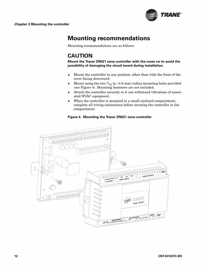
Mounting recommendationsMounting recommendations are as follows:
CAUTIONMount the Tracer ZN521 zone controller with the cover on to avoid the
possibility of damaging the circuit board during installation.
• Mount the controller in any position, other than with the front of the cover facing downward.
• Mount using the two 3/16 in. (4.8 mm) radius mounting holes provided (see Figure 4). Mounting fasteners are not included.
• Attach the controller securely so it can withstand vibrations of associ-ated HVAC equipment.
• When the controller is mounted in a small enclosed compartment, complete all wiring connections before securing the controller in the compartment.
Figure 4. Mounting the Tracer ZN521 zone controller
12 CNT-SVX07C-EN

Chapter 4
Input/output functions and
wiring for typical applications
This chapter provides information about the function of inputs and out-puts and examples of wiring for typical applications. Applications sup-ported by the Tracer ZN521 zone controller are shown in Table 2.
Figures 7 through 17 (pages 23 through 33) show typical wiring diagrams that include all required and all optional components for typical applica-tions.
Table 2. Typical applications for the Tracer ZN521 zone controller
Application
Mu
ltip
le f
an
sp
eed
De
hu
mid
ific
ati
on
Au
to m
inim
um
dam
per
ad
just
Fa
ce
an
d b
yp
ass d
am
pe
r
Va
lve
co
ntr
ol
Eco
no
miz
ing
Au
xil
iary
(b
aseb
oard
) h
ea
t
Ele
ctr
ic h
eat
2-pipe hydronic cooling only x x x x x x
2-pipe hydronic heating only x x x x x x
2-pipe changeover x x x x x x x x
2-pipe steam only x x x x x x
4-pipe hydronic heating and cooling x x x x x x x
4-pipe changeover x x x x x x x
4-pipe steam/chilled water x x x x x
Electric heat only (single- and two-stage) x x ×
DX/hydronic heating x x x x x
DX/steam heating x x x x x
DX cooling only x x x
CNT-SVX07C-EN 13
Chapter 4 Input/output functions and wiring for typical applications
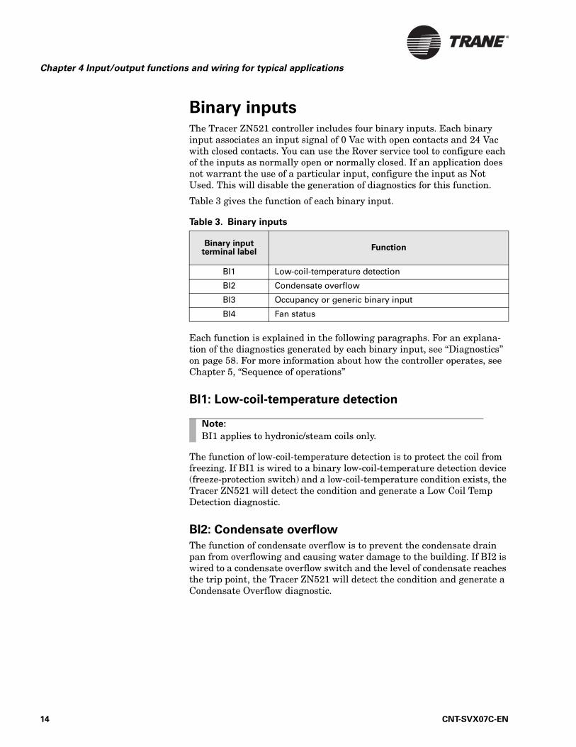
Binary inputsThe Tracer ZN521 controller includes four binary inputs. Each binary input associates an input signal of 0 Vac with open contacts and 24 Vac with closed contacts. You can use the Rover service tool to configure each of the inputs as normally open or normally closed. If an application does not warrant the use of a particular input, configure the input as Not Used. This will disable the generation of diagnostics for this function.
Table 3 gives the function of each binary input.
Each function is explained in the following paragraphs. For an explana-tion of the diagnostics generated by each binary input, see “Diagnostics” on page 58. For more information about how the controller operates, see Chapter 5, “Sequence of operations”
BI1: Low-coil-temperature detection
The function of low-coil-temperature detection is to protect the coil from freezing. If BI1 is wired to a binary low-coil-temperature detection device (freeze-protection switch) and a low-coil-temperature condition exists, the Tracer ZN521 will detect the condition and generate a Low Coil Temp Detection diagnostic.
BI2: Condensate overflow
The function of condensate overflow is to prevent the condensate drain pan from overflowing and causing water damage to the building. If BI2 is wired to a condensate overflow switch and the level of condensate reaches the trip point, the Tracer ZN521 will detect the condition and generate a Condensate Overflow diagnostic.
Table 3. Binary inputs
Binary input terminal label
Function
BI1 Low-coil-temperature detection
BI2 Condensate overflow
BI3 Occupancy or generic binary input
BI4 Fan status
Note:
BI1 applies to hydronic/steam coils only.
14 CNT-SVX07C-EN

Binary inputs
BI3: Occupancy or generic binary input
The BI3 binary input can function as either:
• The occupancy input• A generic binary input
The function of occupancy is to save energy by spreading zone setpoints when the zone is unoccupied. As the occupancy input, BI3 can be used for two related functions. For stand-alone controllers, BI3 can be hard-wired to a binary switch or timeclock to determine the occupancy mode—either occupied or unoccupied. For controllers receiving a BAS-communicated occupancy request, the function of BI3 is to change the mode from occu-pied to occupied standby. (For more information on occupancy-related functions, see “Occupancy modes” on page 36.)
BI3 is the only binary input that can be configured as generic. If config-ured as a generic binary input, it can be monitored by a BAS and has no direct effect on Tracer ZN521 operation.
BI4: Fan status
The fan status input provides feedback to the controller regarding the fan’s operating status. If BI4 is wired to a fan status switch and the input indicates that the fan is not operating when the controller has the fan controlled to on, the controller will generate a Low AirFlow—Fan Failure diagnostic. (For more information, see “Fan status” on page 49.)
CNT-SVX07C-EN 15

Chapter 4 Input/output functions and wiring for typical applications
Analog inputsThe Tracer ZN521 controller includes seven analog inputs. Table 4 describes their functions. Each function is explained in the following paragraphs. For an explanation of the diagnostics generated by each ana-log input, see “Diagnostics” on page 58. For more information about how the controller operates, see Chapter 5, “Sequence of operations”
GND: Ground terminals
Use a GND terminal as the common ground for all zone sensor analog inputs.
ZN: Zone temperature
The ZN analog input functions as the local (hard-wired) zone temperature input. The controller receives the temperature as a resistance signal from a 10 kΩ thermistor in a standard Trane zone sensor wired to analog input ZN. A zone temperature value communicated by means of a LonTalk link can also be used for controllers operating on a BAS. When both a hard-wired and communicated zone temperature value is present, the control-ler uses the communicated value. If neither a hard-wired nor a communi-cated zone temperature value is present, the controller generates a Zone Temp Failure diagnostic.
The ZN analog input is also used to communicate timed override requests and cancel requests to the controller for applications using a Trane zone sensor with ON and CANCEL buttons.
Table 4. Analog inputs
Analog input terminal label
Function
ZN Zone temperature
GND Zone sensor common ground
SET Local setpoint
FAN Fan mode input
GND Auxiliary ground
AI1 Entering water temperature
AI2 Discharge air temperature
AI3 Outdoor air temperature or generic temperature
AI4 Universal 4–20 mA
16 CNT-SVX07C-EN

Analog inputs
SET: Local setpoint
The SET analog input functions as the local (hard-wired) temperature setpoint input for applications utilizing a Trane zone sensor with a tem-perature setpoint thumbwheel. The local setpoint input is configurable (as enabled or disabled) using the Rover service tool. A setpoint value communicated by means of a LonTalk link can also be used for controllers operating on a BAS. If both hard-wired and communicated setpoint val-ues are present, the controller uses the communicated value. If neither a hard-wired nor a communicated setpoint value is present, the controller uses the stored default setpoints (configurable using the Rover service tool). If a valid hard-wired or communicated setpoint value is established and then is no longer present, the controller generates a Setpoint Failure diagnostic.
FAN: Fan mode input
The FAN analog input functions as the local (hard-wired) fan mode switch input for applications using the Trane zone sensor with a fan mode switch option. The various fan mode switch positions (off, low, medium, high, auto) provide different resistances that are interpreted by the Tracer ZN521. The local fan mode switch input is configurable (as enabled or disabled) using the Rover service tool. A communicated fan mode request via the LonTalk communications link can also be used for controllers operating on a BAS. If both hard-wired and communicated fan mode values are present, the controller uses the communicated value. If neither a hard-wired nor a communicated fan mode value is present, the controller recognizes the fan mode value as auto and operates according to the default configuration. If a valid hard-wired or communicated fan mode value is established and then is no longer present, the controller generates a Fan Mode Failure diagnostic.
AI1: Entering water temperature
The AI1 analog input functions as the local (hard-wired) entering water temperature input. An entering water temperature communicated via the LonTalk communications link can also be used for controllers operating on a BAS. If both hard-wired and communicated entering water tempera-ture values are present, the controller uses the communicated value. If a valid hard-wired or communicated entering water temperature value is established and then is no longer present, the controller generates an Entering Water Temp Failure diagnostic.
For units configured as 2-pipe or 4-pipe changeover units, the entering water temperature is used to make heating/cooling operation decisions. If neither a hard-wired nor a communicated entering water temperature value is present on changeover units, the controller will always operate in heating mode.
CNT-SVX07C-EN 17

Chapter 4 Input/output functions and wiring for typical applications
For units not configured as changeover units, the entering water temper-ature value is used for information and troubleshooting only and does not affect the operation of the controller.
AI2: Discharge air temperature
The AI2 analog input functions as the local discharge air temperature input.
IMPORTANTThe Tracer ZN521 cannot operate without a valid discharge air tempera-
ture value.
The controller receives the temperature as a resistance signal from a 10 kΩ thermistor wired to analog input AI2. The thermistor is typically located downstream from all unit heating and cooling coils at the unit dis-charge area.
If a discharge air temperature value is invalid or is not present, the con-troller generates a Discharge Air Temp Failure diagnostic and shuts down the equipment. When the thermistor returns to a valid tempera-ture, the controller automatically allows the equipment to resume normal operation.
AI3: Outdoor air temperature or generic temperature
The AI3 analog input can function as either:
• An outdoor air temperature input• A generic temperature input
If AI3 is configured as the local (hard-wired) outdoor air temperature input, the controller receives the temperature as a resistance signal from a 10 kΩ thermistor wired to analog input AI3. An outdoor air tempera-ture value communicated by means of a LonTalk link can also be used for controllers operating on a BAS. If both hard-wired and communicated outdoor air temperature values are present, the controller uses the com-municated value. If a valid hard-wired or communicated outdoor air tem-perature value is established and then is no longer present, the controller generates an Outdoor Air Temp Failure diagnostic.
Note:
AI1 is not polarity sensitive; you can connect either terminal to either sensor lead.
Note:
AI2 is not polarity sensitive; you can connect either terminal to either sensor lead.
18 CNT-SVX07C-EN

Analog inputs
Economizing (free cooling) is a function whereby outdoor air is used as a source of cooling before hydronic or DX cooling is used. The Tracer ZN521 uses the outdoor air temperature value to determine whether economiz-ing is feasible. Economizing is not possible without a valid outdoor air temperature. (For more information, see “Economizing (free cooling)” on page 45.)
The outdoor air temperature value is also used for the freeze avoidance function. This function is used for low-coil-temperature protection when the fan is off. The controller enters the freeze avoidance mode when the outdoor air temperature is below the freeze avoidance setpoint (config-urable using the Rover service tool). (For more information, see “Freeze avoidance” on page 50.)
If AI3 is configured as a generic temperature input, it can be monitored by a BAS. The controller receives the temperature as a resistance signal from a 10 kΩ thermistor wired to analog input AI3. The generic tempera-ture input can be used with any Trane 10 kΩ thermistor. The thermistor can be placed in any location and has no effect on the operation of the con-troller. The controller will generate a Generic Temperature Failure diag-nostic if the input becomes invalid or goes out of range.
AI4: Universal 4–20 mA
The AI4 analog input can be configured in one of the three ways shown in Table 5.
If this input is not needed for an application, configure it as Not Used. This will disable the generation of diagnostics.
For the generic input configuration, a 4–20 mA sensor must be hard-wired to the AI4 terminal. (Wiring is dependent on the specific applica-tion.) The sensor communicates a value of 0–100% to the BAS. This con-figuration has no direct effect on Tracer ZN521 operation. If a valid value
Note:
AI3 is not polarity sensitive; you can connect either terminal to either sensor lead.
Table 5. AI4 configuration options and associated measurement ranges
Configuration Measurement range
Generic 4–20 mA input 0–100% (4 mA=0%; 20 mA=100%)
CO2 measurement 0–2000 ppm(4 mA=0 ppm; 20 mA=2000 ppm)
Relative humidity (RH) measurement 0–100%(4 mA=0% RH; 20 mA=100% RH)
Note:
AI4 is polarity sensitive.
CNT-SVX07C-EN 19

Chapter 4 Input/output functions and wiring for typical applications
is established and then is no longer present, the controller generates a Generic AIP Failure diagnostic.
For the CO2 measurement configuration, a 4–20 mA sensor must be hard-wired to the AI4 terminal as shown in Figure 5. The sensor will transmit a 0–2000 ppm value to the BAS. This configuration has no direct effect on Tracer ZN521 operation. If a valid value is established and then is no longer present, the controller generates a CO2 Sensor Failure diagnostic.
Figure 5. AI4 terminal wiring: CO2 measurement
For the RH measurement configuration, either a hard-wired 4–20 mA zone humidity sensor (see Figure 6) must provide a value to the controller or a BAS communicates a value to the controller. The controller uses this value to support the dehumidification function. (For more information, see “Dehumidification” on page 47.) If a valid hard-wired or communi-cated relative humidity value is established and then is no longer present, the controller generates a Humidity Input Failure diagnostic and disables the dehumidification function.
Figure 6. AI4 terminal wiring: RH measurement
Tracer ZN521
24 Vac
CO2 sensor(Trane 5010 0828 shown)
24 VacGND Signal
Tracer ZN521
RH sensor
20 CNT-SVX07C-EN

Binary outputs
Binary outputsThe ZN521 zone controller supports fan coil, blower coil, and unit ventila-tor applications that may include the following components:
• Supply fan with up to three speeds• Hydronic cooling and/or heating coils with two-position or tri-state
modulating control valve• DX cooling (single stage)• Electric heat (single stage or two stage)• Baseboard heat (single stage)• Tri-state modulating outdoor/return air damper• Tri-state modulating face-and-bypass damper
The Tracer ZN521 controller includes ten binary outputs. Each binary output is a triac with a rating of 12 VA at 24 Vac. Table 6 describes the function of each output.
Generic binary output
Binary output 10 is the only output that can be configured as a generic binary output. When configured as a generic binary output, it can be con-trolled only by a BAS, and has no direct effect on Tracer ZN521 operation.
Table 6: Binary output functions
Binary output Functions
1 • Fan high
2 • Fan medium• Exhaust fan or damper
3 • Fan low
4 • Modulating cooling/changeover valve, open• Two-position cooling/changeover valve• DX cooling
5 • Modulating cooling/changeover valve, close• Face-and-bypass damper, open to face
6 • Modulating heating valve, open• Two-position heating valve• Electric heat, stage 1
7 • Modulating heating valve, close• Face-and-bypass damper, close (bypass)• Electric heat, stage 2
8 • Outdoor air damper, open (return air damper, close)
9 • Outdoor air damper, close (return air damper, open)
10 • Baseboard heat• Generic
CNT-SVX07C-EN 21

Chapter 4 Input/output functions and wiring for typical applications
Overriding binary outputs
The Tracer ZN521 controller includes a manual output test and a water valve override feature. Use the manual output test to manually control the outputs in a defined sequence. For information, see “Manual output test” on page 52.
The water valve override feature is a procedure used for water balancing. Using the Rover service tool or a BAS, a user can specify that a Tracer ZN521 override the state of water valves to:
• Open all valves• Close all valves
The controller resets itself to normal operation after two hours.
Wiring requirements and optionsTable 7 shows required controller inputs for minimal proper operation of all applications.
Figure 7 on page 23 through Figure 17 on page 33 show typical applica-tions that include all required and all optional components.
Table 7. Required controller inputs for proper operation
Function Input sourceFor more information,
see:
24 Vac power Terminals: GND, 24 V “AC-power wiring” on page 7
Zone temperature Terminals: ZN, GNDor communicated
“ZN: Zone tempera-ture” on page 16
Discharge air temperature Terminals: AI2 “AI2: Discharge air tem-perature” on page 18
Entering water tempera-ture—required only for units with auto changeover
Terminal: AI1or communicated
“AI1: Entering water temperature” on page 17
Outdoor air temperature—required only for econo-mizing
Terminals: AI3 or communicated
“AI3: Outdoor air tem-perature or generic temperature” on page 18
Relative humidity—required only for dehu-midification
Terminals: AI4 “AI4: Universal 4–20 mA” on page 19
22 CNT-SVX07C-EN
Wiring requirements and options
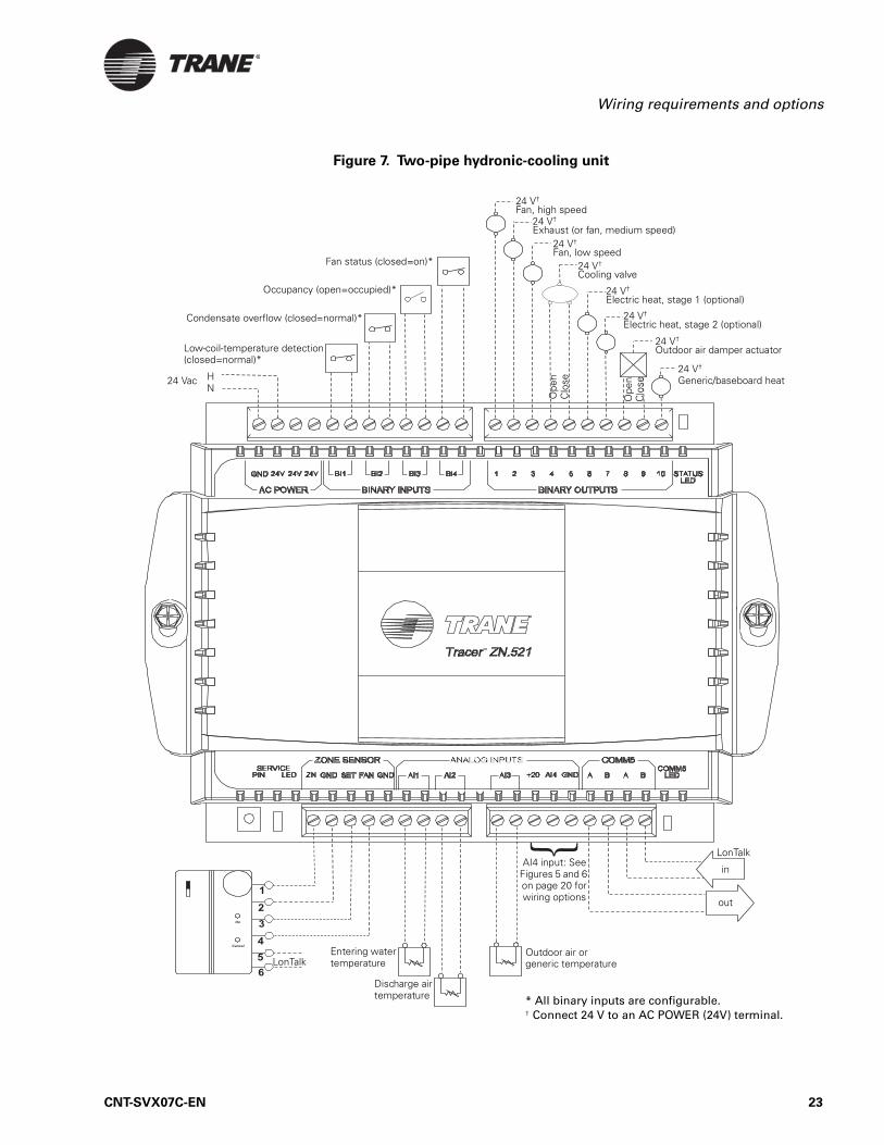
Figure 7. Two-pipe hydronic-cooling unit
LonTalk
in
Entering water temperature
Outdoor air or generic temperature
24 V†
Exhaust (or fan, medium speed)24 V†
Fan, low speed24 V†
Cooling valve
24 V†
Fan, high speed
Low-coil-temperature detection (closed=normal)*
Condensate overflow (closed=normal)*
Occupancy (open=occupied)*
LonTalk
HN
24 Vac24 V†
Generic/baseboard heat
24 V†
Electric heat, stage 1 (optional)
out
Fan status (closed=on)*
24 V†
Electric heat, stage 2 (optional)
24 V†
Outdoor air damper actuator
AI4 input: See Figures 5 and 6 on page 20 for wiring options
Discharge air temperature
Ope
nC
lose
Ope
nC
lose
* All binary inputs are configurable.† Connect 24 V to an AC POWER (24V) terminal.
CNT-SVX07C-EN 23
Chapter 4 Input/output functions and wiring for typical applications
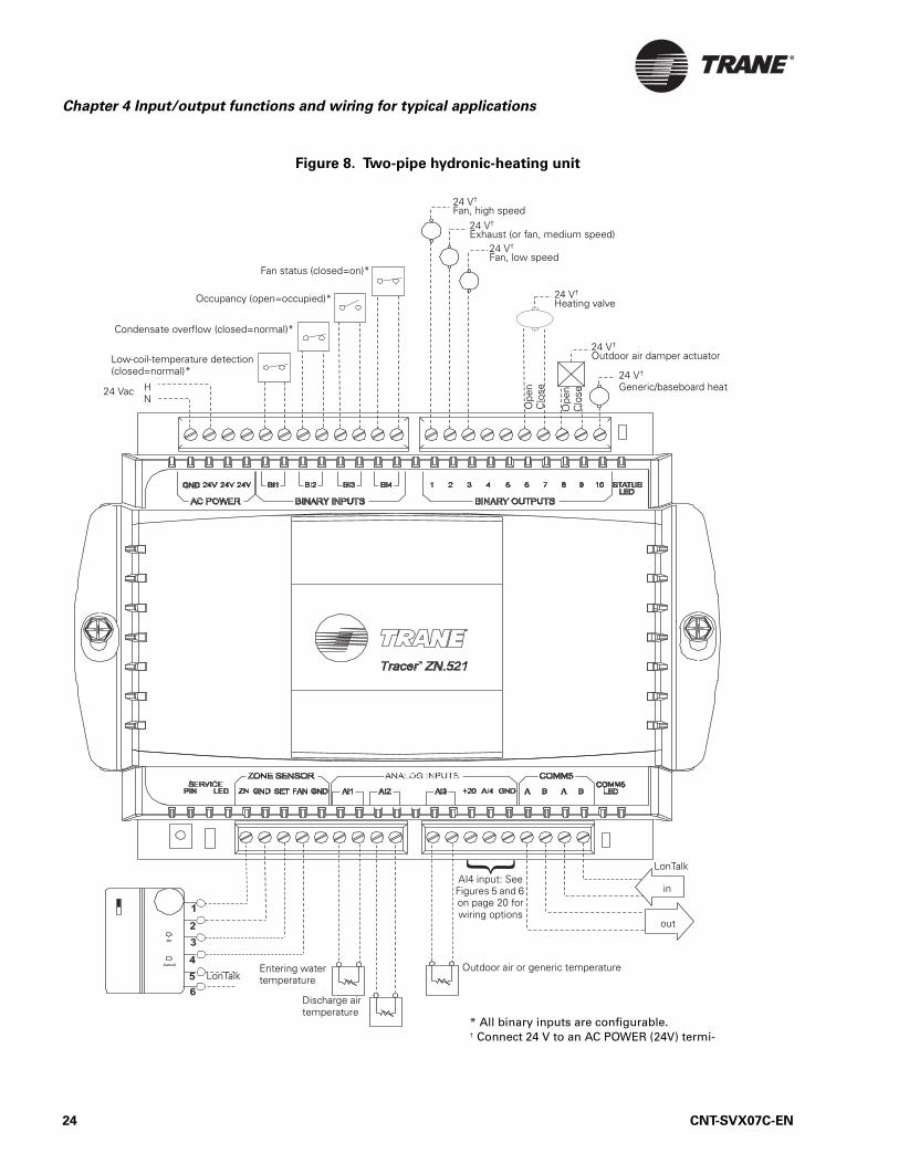
Figure 8. Two-pipe hydronic-heating unit
in
Entering water temperature
Outdoor air or generic temperature
24 V†
Exhaust (or fan, medium speed)24 V†
Fan, low speed
24 V†
Fan, high speed
Condensate overflow (closed=normal)*
Occupancy (open=occupied)*
LonTalk
HN
24 Vac
24 V†
Generic/baseboard heat
24 V†
Heating valve
out
Fan status (closed=on)*
24 V†
Outdoor air damper actuator
Discharge air temperature
Ope
nC
lose
Ope
nC
lose
Low-coil-temperature detection (closed=normal)*
LonTalk
* All binary inputs are configurable.† Connect 24 V to an AC POWER (24V) termi-
AI4 input: See Figures 5 and 6 on page 20 for wiring options
24 CNT-SVX07C-EN

Wiring requirements and options
Figure 9. Two-pipe hydronic heating/cooling unit with auto changeover
LonTalk
Entering water temperature
Outdoor air or generic temperature
24 V†
Exhaust (or fan, medium speed)24 V†
Fan, low speed
24 V†
Fan, high speed
Low-coil-temperature detection (closed=normal)*
Condensate overflow (closed=normal)*
Occupancy (open=occupied)*
LonTalk
HN
24 Vac24 V†
Generic/baseboard heat
24 V†
Heating/cooling changeover valve
* All binary inputs are configurable.† Connect 24 V to an AC POWER (24V) terminal.
Fan status (closed=on)*
24 V†
Outdoor air damper actuator
Discharge air temperature
24 V†
Electric heat, stage 1 (optional)
24 V†
Electric heat, stage 2 (optional)
Ope
nC
lose
Ope
nC
lose
in
out
AI4 input: See Figures 5 and 6 on page 20 for wiring options
CNT-SVX07C-EN 25
Chapter 4 Input/output functions and wiring for typical applications
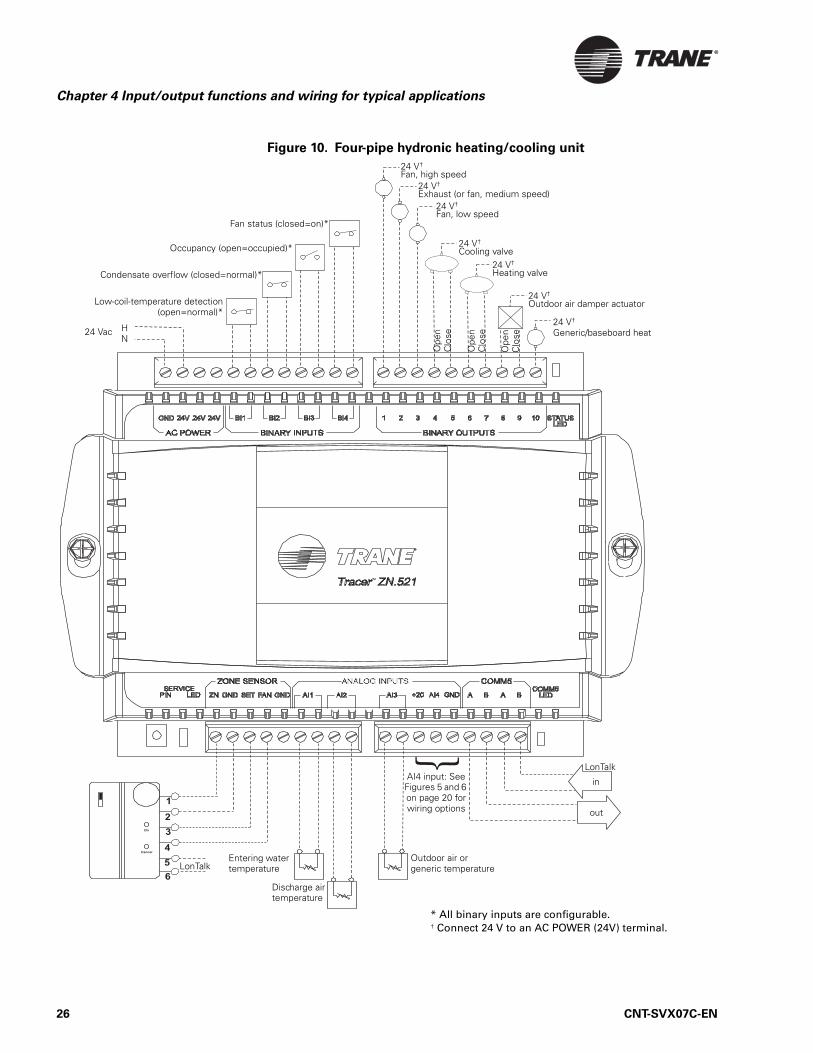
Figure 10. Four-pipe hydronic heating/cooling unit
LonTalk
in
Entering water temperature
Outdoor air or generic temperature
24 V†
Exhaust (or fan, medium speed)24 V†
Fan, low speed
24 V†
Fan, high speed
Low-coil-temperature detection(open=normal)*
Condensate overflow (closed=normal)*
Occupancy (open=occupied)*
LonTalk
HN
24 Vac24 V†
Generic/baseboard heat
24 V†
Cooling valve
out
Fan status (closed=on)*
24 V†
Outdoor air damper actuator
Discharge air temperature
24 V†
Heating valve
Ope
nC
lose
Ope
nC
lose
Ope
nC
lose
* All binary inputs are configurable.† Connect 24 V to an AC POWER (24V) terminal.
AI4 input: See Figures 5 and 6 on page 20 for wiring options
26 CNT-SVX07C-EN

Wiring requirements and options
Figure 11. Four-pipe heating/cooling unit with auto changeover
LonTalk
in
Outdoor air or generic temperature
24 V†
Exhaust (or fan, medium speed)24 V†
Fan, low speed
24 V†
Fan, high speed
Low-coil-temperature detection (closed=normal)*
Condensate overflow (closed=normal)*
Occupancy (open=occupied)*
LonTalk
HN
24 Vac24 V†
Generic/baseboard heat
24 V†
Heating/cooling changeover valve
out
Fan status (closed=on)*
24 V†
Outdoor air damper actuator
Discharge air temperature
24 V†
Auxiliary heating valve
Ope
nC
lose
Ope
nC
lose
Entering water temperature
Ope
nC
lose
* All binary inputs are configurable.† Connect 24 V to an AC POWER (24V) terminal.
AI4 input: See Figures 5 and 6 on page 20 for wiring options
CNT-SVX07C-EN 27

Chapter 4 Input/output functions and wiring for typical applications
Figure 12. Two-pipe heating unit with DX cooling
LEDA BBAAI4+20 GNDAI2 AI3FAN GND AI1ZN GNDLED SETPIN
ZONE SENSOR
SERVICE
ANALOG INPUTS COMM5
COMM5
AC POWER
24V24VGND 24V
BINARY INPUTS
BI3BI1 BI2 BI4
BINARY OUTPUTS
21 43 765 8 9
LED
STATUS10
5
4
3
2
1
On
Cancel
6
LonTalk
in
Entering water temperature
Outdoor air or generic temperature
24 V†
Exhaust (or fan, medium speed)24 V†
Fan, low speed
24 V†
Fan, high speed
Low-coil-temperature detection (closed=normal)*
Condensate overflow (closed=normal)*
Occupancy (open=occupied)*
LonTalk
HN
24 Vac24 V†
Generic/baseboard heat
24 V†
DX cooling
out
Fan status (closed=on)*
24 V†
Outdoor air damper actuator
Discharge air temperature
24 V†
Heating valve
Ope
nC
lose
Ope
nC
lose
* All binary inputs are configurable.† Connect 24 V to an AC POWER (24V) terminal.
AI4 input: See Figures 5 and 6 on page 20 for wiring options
28 CNT-SVX07C-EN

Wiring requirements and options
Figure 13. Electric heat unit with DX cooling
LEDA BBAAI4+20 GNDAI2 AI3FAN GND AI1ZN GNDLED SETPIN
ZONE SENSOR
SERVICE
ANALOG INPUTS COMM5
COMM5
AC POWER
24V24VGND 24V
BINARY INPUTS
BI3BI1 BI2 BI4
BINARY OUTPUTS
21 43 765 8 9
LED
STATUS10
5
4
3
2
1
On
Cancel
6
LonTalkin
Entering water temperature
Outdoor air or generic temperature
24 V†
Exhaust
24 V†
Fan, high speed
Low-coil-temperature detection (closed=normal)*
Condensate overflow (closed=normal)*
Occupancy (open=occupied)*
LonTalk
HN
24 Vac24 V†
Generic/baseboard heat
24 V†
DX cooling
out
Fan status (closed=on)*
24 V†
Outdoor air damper actuator
Discharge air temperature
24 V†
Electric heat, stage 2 (optional)
Ope
nC
lose
24 V†
Electric heat, stage 1 (optional)
AI4 input: See Figures 5 and 6 on page 20 for wiring options
* All binary inputs are configurable.† Connect 24 V to an AC POWER (24V) terminal.
CNT-SVX07C-EN 29
Chapter 4 Input/output functions and wiring for typical applications
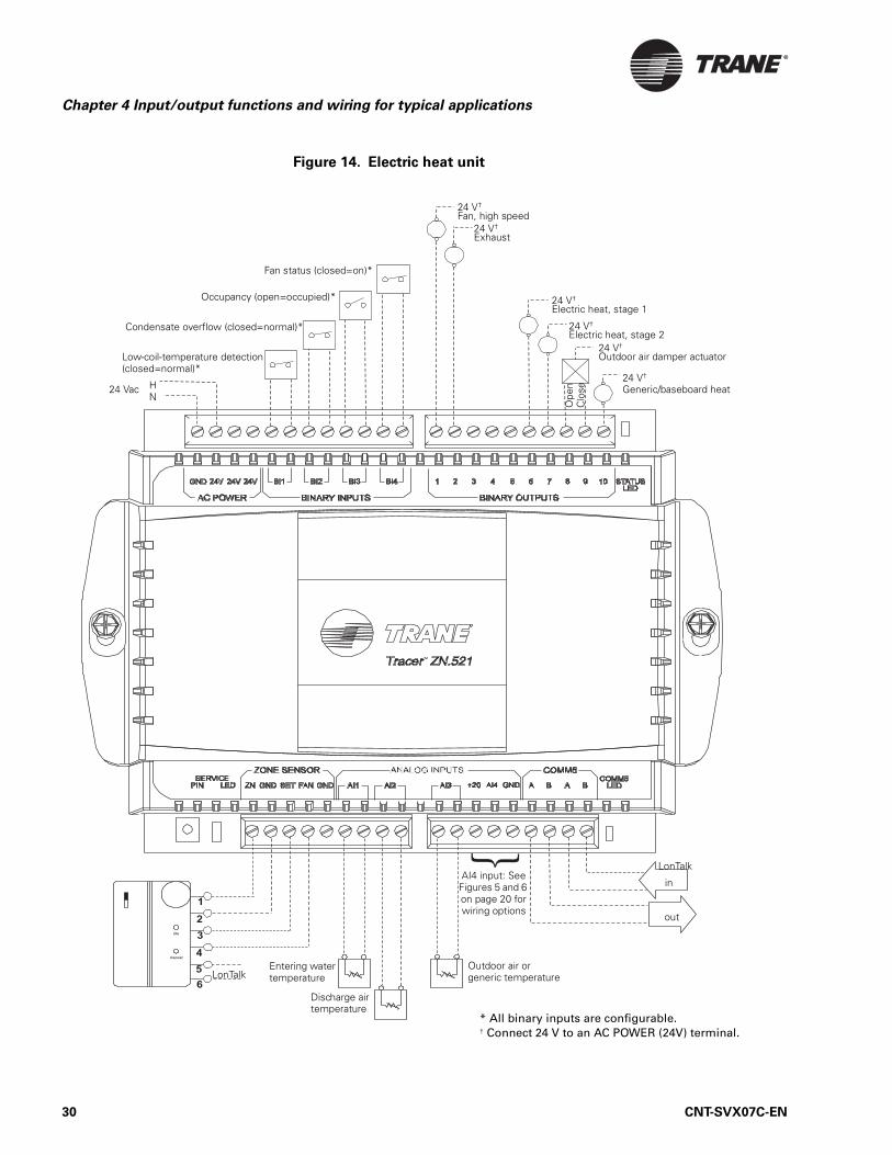
Figure 14. Electric heat unit
LonTalk
in
Entering water temperature
Outdoor air or generic temperature
24 V†
Exhaust
24 V†
Fan, high speed
Low-coil-temperature detection (closed=normal)*
Condensate overflow (closed=normal)*
Occupancy (open=occupied)*
LonTalk
HN
24 Vac24 V†
Generic/baseboard heat
24 V†
Electric heat, stage 1
out
Fan status (closed=on)*
24 V†
Outdoor air damper actuator
Discharge air temperature
24 V†
Electric heat, stage 2
Ope
nC
lose
* All binary inputs are configurable.† Connect 24 V to an AC POWER (24V) terminal.
AI4 input: See Figures 5 and 6 on page 20 for wiring options
30 CNT-SVX07C-EN

Wiring requirements and options
Figure 15. Two-pipe heating unit with face-and-bypass damper
LonTalk
in
Entering water temperature
Outdoor air or generic temperature
24 V†
Exhaust (or fan, medium speed)24 V†
Fan, low speed
24 V†
Fan, high speed
Low-coil-temperature detection (closed=normal)*
Condensate overflow (closed=normal)*
Occupancy (open=occupied)*
LonTalk
HN
24 Vac24 V†
Generic/baseboard heat
out
Fan status (closed=on)*
24 V†
Outdoor air damper actuator
Discharge air temperature
24 V†
Face & bypass damper actuator
Ope
nC
lose
Clo
se
Ope
n
24 V†
Heat isolation valve, open/close
* All binary inputs are configurable.† Connect 24 V to an AC POWER (24V) terminal.
AI4 input: See Figures 5 and 6 on page 20 for wiring options
CNT-SVX07C-EN 31

Chapter 4 Input/output functions and wiring for typical applications
Figure 16. Two-pipe heating/cooling unit with face-and-bypass damper
LonTalk
in
Entering water temperature
Outdoor air or generic temperature
24 V†
Exhaust (or fan, medium speed)
24 V†
Fan, low speed
24 V†
Fan, high speed
Low-coil-temperature detection (closed=normal)*
Condensate overflow (closed=normal)*
Occupancy (open=occupied)*
LonTalk
HN
24 Vac24 V†
Generic/baseboard heat
24 V†
Heating/cooling isolation valve, open/close
out
Fan status (closed=on)*
24 V†
Outdoor air damper actuator
Discharge air temperature
24 V†
Face-and-bypass damper actuator
Ope
nC
lose
Ope
n
* All binary inputs are configurable.† Connect 24 V to an AC POWER (24V) terminal.
Clo
se
AI4 input: See Figures 5 and 6 on page 20 for wiring options
32 CNT-SVX07C-EN

Wiring requirements and options
Figure 17. Four-pipe heating/cooling unit with face-and-bypass damper
LonTalk
in
Entering water temperature
Outdoor air or generic temperature
24 V†
Exhaust (or fan, medium speed)
24 V†
Fan, low speed
24 V†
Fan, high speed
Low-coil-temperature detection (closed=normal)*
Condensate overflow (closed=normal)*
Occupancy (open=occupied)*
LonTalk
HN
24 Vac24 V†
Generic/baseboard heat
24 V†
Face and bypass damper actuator
out
Fan status (closed=on)*
24 V†
Outdoor air damper actuator
Discharge air temperature
24 V†
Heating isolation valve, open/close
Ope
nC
lose
Ope
n
24 V†
Cooling isolation valve, open/close
Clo
se
* All binary inputs are configurable.† Connect 24 V to an AC POWER (24V) terminal.
AI4 input: See Figures 5 and 6 on page 20 for wiring options
CNT-SVX07C-EN 33

Chapter 4 Input/output functions and wiring for typical applications
34 CNT-SVX07C-EN

Chapter 5
Sequence of operations
The Tracer ZN521 zone controller will operate to maintain the zone tem-perature setpoint. This chapter discusses many of the operational sequences used by the controller to accomplish this goal.
Power-up sequenceWhen 24 Vac power is initially applied to the Tracer ZN521 zone control-ler, the following sequence occurs:
1. The green status indicator LED turns on (see “Interpreting LEDs” on page 56).
2. All outputs are controlled off. All modulating valves and dampers close, and the face-and-bypass damper calibrates to bypass (when present).
3. The controller reads all input local values to determine initial values.
4. The random-start timer begins (see “Random start” on page 35).
5. If a hard-wired zone-temperature value is not detected, the controller begins to wait for a communicated value. (This can take several min-utes [15-minute default] and occurs concurrently with the remainder of the power-up sequence.)
6. The random-start timer expires.
7. The power-up control wait function begins automatically if the config-ured power-up control wait time is greater than 0 seconds. When this function is enabled, the controller waits for the configured amount of time (from 0 to 120 seconds) to allow a communicated occupancy request to arrive. If a communicated occupancy request arrives, nor-mal operation can begin. If a communicated occupancy request does not arrive, the controller assumes stand-alone operation.
8. Normal operation begins assuming no diagnostics have been generated.
Random startRandom start is intended to prevent all units in a building from energiz-ing at the same time. The random-start timer delays the fan and any heating or cooling start-up from 5 to 30 seconds. If neither heating nor cooling is initiated, or if fan operation is not required during the delay, the random-start timer will time-out.
CNT-SVX07C-EN 35

Chapter 5 Sequence of operations
Occupancy modesOccupancy modes can be controlled by any of the following:
• The state of the local (hard-wired) occupancy binary input BI3 (see “BI3: Occupancy or generic binary input” on page 15)
• A timed override request from a Trane zone sensor (see “Timed over-ride control” on page 37)
• A communicated signal from a peer device (see “Peer-to-peer commu-nication” on page 48)
• A communicated signal from a BAS
A communicated request, either from a BAS or a peer controller, takes precedence over local requests. If a communicated occupancy request has been established and is no longer present, the controller reverts to the default (occupied) occupancy mode after 15 minutes (if no hard-wired occupancy request exists). The Tracer ZN521 has the following occupancy mode options:
• Occupied• Unoccupied• Occupied standby• Occupied bypass
Occupied mode
In occupied mode, the controller maintains the zone temperature based on the occupied heating or cooling setpoints. The controller uses the occu-pied mode as a default mode when other forms of occupancy request are not present. The fan will run as configured (continuous or cycling). The outdoor air damper will close when the fan is off. The temperature set-points can be local (hard-wired), communicated, or stored default values (configurable using the Rover service tool).
Unoccupied mode
In unoccupied mode, the controller attempts to maintain the zone temper-ature based on the unoccupied heating or cooling setpoint. The fan will cycle between high speed and off. The outdoor air damper will remain closed, unless economizing. The controller always uses the stored default setpoint values (configurable using the Rover service tool), regardless of the presence of a hard-wired or communicated setpoint value.
Occupied standby mode
The controller is placed in occupied standby mode only when a communi-cated occupied request is combined with an unoccupied request from occupancy binary input BI3. In occupied standby mode, the controller maintains the zone temperature based on the occupied standby heating or cooling setpoints. Because the occupied standby setpoints are typically spread 2°F (1.1°C) in either direction and the outdoor air damper is closed, this mode reduces the demand for heating and cooling the space.
36 CNT-SVX07C-EN

Timed override control
The fan will run as configured (continuous or cycling) for occupied mode. The controller always uses the stored default setpoint values (config-urable using the Rover service tool), regardless of hard-wired or commu-nicated setpoint values. In addition, the outdoor air damper uses the Economizer Occupied Standby Minimum Position setpoint to reduce the ventilation rate.
Occupied bypass mode
The controller is placed in occupied bypass mode when the controller is operating in the unoccupied mode and either the timed override ON but-ton on the Trane zone sensor is pressed or the controller receives a com-municated occupied bypass signal from a BAS. In occupied bypass mode, the controller maintains the zone temperature based on the occupied heating or cooling setpoints. The fan will run as configured (continuous or cycling). The outdoor air damper will close when the fan is off. The con-troller will remain in occupied bypass mode until either the CANCEL but-ton is pressed on the Trane zone sensor or the occupied bypass time (configurable using the Rover service tool) expires. The temperature set-points can be local (hard-wired), communicated, or stored default values (also configurable using the Rover service tool).
Timed override control If the zone sensor has a timed override option (ON/CANCEL buttons), push-ing the ON button initiates a timed override on request. A timed override on request changes the occupancy mode from unoccupied mode to occu-pied bypass mode. In occupied bypass mode, the controller controls the zone temperature based on the occupied heating or cooling setpoints. The occupied bypass time, which resides in the Tracer ZN521 and defines the duration of the override, is configurable from 0 to 240 minutes (default value of 120 minutes). When the occupied bypass time expires, the unit transitions from occupied bypass mode to unoccupied mode. Pushing the CANCEL button cancels the timed override request. A timed override can-cel request will end the timed override before the occupied bypass time has expired and will transition the unit from occupied bypass mode to unoccupied mode.
If the controller is in any mode other than unoccupied when the ON but-ton is pressed, the controller still starts the occupied bypass timer with-out changing the mode to occupied bypass. If the controller is placed in unoccupied mode before the occupied bypass timer expires, the controller will be placed in occupied bypass mode and remain in that mode until either the CANCEL button is pressed on the Trane zone sensor or the occu-pied bypass time expires.
CNT-SVX07C-EN 37
Chapter 5 Sequence of operations
Zone temperature controlThe Tracer ZN521 zone controller uses two methods of zone temperature control:
• Cascade zone control—used in the occupied, occupied bypass, and occupied standby modes
• Simplified zone control—used in the unoccupied mode
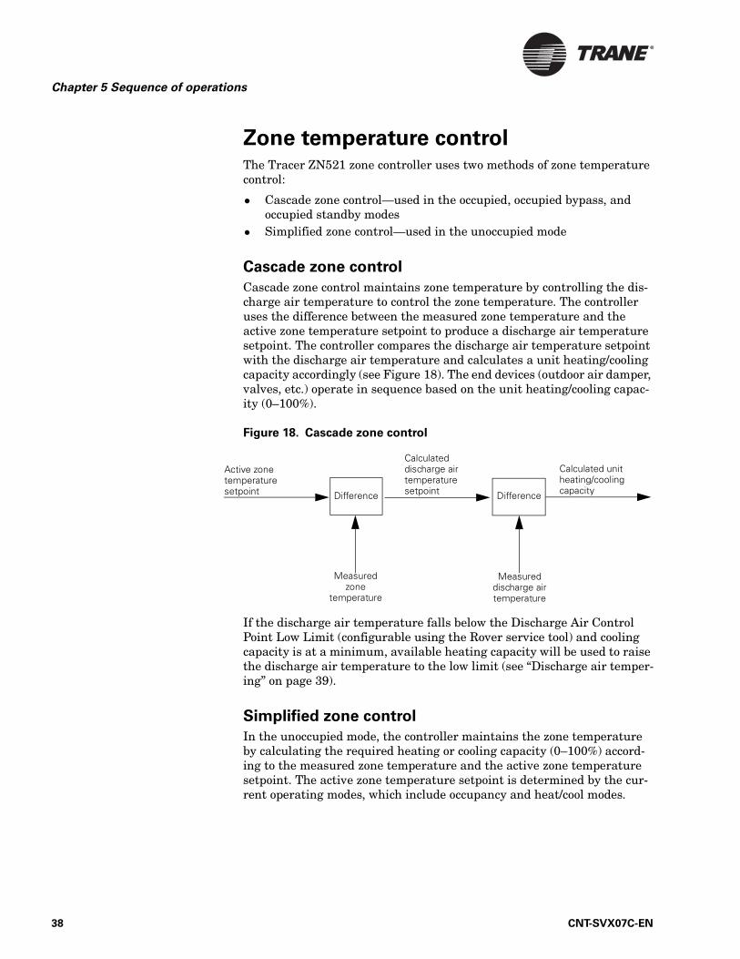
Cascade zone control
Cascade zone control maintains zone temperature by controlling the dis-charge air temperature to control the zone temperature. The controller uses the difference between the measured zone temperature and the active zone temperature setpoint to produce a discharge air temperature setpoint. The controller compares the discharge air temperature setpoint with the discharge air temperature and calculates a unit heating/cooling capacity accordingly (see Figure 18). The end devices (outdoor air damper, valves, etc.) operate in sequence based on the unit heating/cooling capac-ity (0–100%).
Figure 18. Cascade zone control
If the discharge air temperature falls below the Discharge Air Control Point Low Limit (configurable using the Rover service tool) and cooling capacity is at a minimum, available heating capacity will be used to raise the discharge air temperature to the low limit (see “Discharge air temper-ing” on page 39).
Simplified zone control
In the unoccupied mode, the controller maintains the zone temperature by calculating the required heating or cooling capacity (0–100%) accord-ing to the measured zone temperature and the active zone temperature setpoint. The active zone temperature setpoint is determined by the cur-rent operating modes, which include occupancy and heat/cool modes.
Active zone temperature setpoint Difference
Calculated discharge air temperature setpoint
Calculated unit heating/cooling capacity
Measured zone
temperature
Measured discharge air temperature
Difference
38 CNT-SVX07C-EN

Discharge air tempering
Discharge air temperingIf the controller is in cooling mode, cascade zone control initiates a dis-charge air tempering function when the discharge air temperature falls below the Discharge Air Control Point Low Limit (configurable using the Rover service tool) and all cooling capacity is at a minimum. The dis-charge air tempering function allows the controller to provide heating capacity (if available) to raise the discharge air temperature to the Dis-charge Air Control Point Low Limit.
The discharge air tempering function is often initiated under the follow-ing circumstances: Cold outdoor air is brought in through the outdoor air damper when the damper is at (a high) minimum position, causing the discharge air temperature to fall below the Discharge Air Control Point Low Limit.
Morning warm-upThe morning warm-up feature is initiated when the controller is in tran-sition from unoccupied to occupied mode and the zone temperature is 3°F (1.7°C) below the occupied heating setpoint. The fan will be turned on and the outdoor air damper will remain closed. The damper modulates between closed and minimum position when the zone temperature is 2–3°F (1.2–1.7°C) below the active heating setpoint. When the zone tem-perature reaches the occupied heating setpoint, the controller begins operating in the occupied mode.
Morning cool-downThe morning cool-down feature is initiated when the controller is in tran-sition from unoccupied to occupied and the zone temperature is 3°F (1.7°C) above the occupied heating setpoint. The fan will be turned on and the outdoor air damper will remain closed. The damper modulates between closed and minimum position when the zone temperature is 2–3°F (1.2–1.7°C) above the active cooling setpoint. When the zone tem-perature reaches the occupied heating setpoint, the controller begins operating in the occupied mode.
Heating or cooling modeThe heating or cooling mode can be determined in one of two ways:
• By a communicated signal from a BAS or a peer controller• Automatically, as determined by the controller
A communicated heating signal permits the controller to heat only. A communicated cooling signal permits the controller to cool only. A com-municated auto signal allows the controller to automatically change from heating to cooling and vice versa.
CNT-SVX07C-EN 39

Chapter 5 Sequence of operations
In heating and cooling mode, the controller maintains the zone tempera-ture based on the active heating setpoint and the active cooling setpoint, respectively. The active heating and cooling setpoints are determined by the occupancy mode of the controller.
For two-pipe and four-pipe changeover units, normal heat/cool operation will not begin until the ability to conduct the desired heating or cooling operation is verified. This is done using the entering water temperature sampling function, for which a valid entering water temperature is required. When neither a hard-wired nor a communicated entering water temperature value is present on changeover units, the controller will operate in heating mode only and assume the coil water is hot. The sam-pling function is not used.
The entering water temperature sampling function is used only for changeover applications. It is used for information and troubleshooting only and does not affect the operation of the controller. (For more informa-tion, see “Entering water temperature sampling function.”)
Entering water temperature sampling
functionThe entering water temperature sampling function is used with two-pipe and four-pipe changeover units and requires a valid entering water tem-perature value. If the entering water temperature value is less than 5°F (2.8°C) above a valid zone temperature value for hydronic heating and greater than 5°F (2.8°C) below a valid zone temperature value for hydronic cooling, the sampling function is enabled. When the sampling function is enabled, the controller opens the main hydronic valve to allow the water temperature to stabilize. After 3 minutes, the controller again compares the entering water temperature value to the zone temperature value to determine if the desired heating or cooling function can be accomplished. If the entering water temperature value remains out of range to accomplish the desired heating/cooling function, the controller closes the main hydronic valve and waits 60 minutes to attempt another sampling. If the entering water temperature value falls within the required range, it resumes normal heating/cooling operation and disables the sampling function.
Fan operationThe Tracer ZN521 supports up to three fan speeds. Every time the fan is enabled, the fan will begin operation and run on high speed for a period of time (0.5 seconds for fan coils and 3 seconds for unit ventilators and blower coils) before changing to any other speed. This is done to provide adequate torque to start the fan motor from the off position. The fan will always operate continuously while either heating or cooling during occu-pied, occupied standby, and occupied bypass operation. During unoccu-pied operation, the fan will cycle between off and high regardless of the
40 CNT-SVX07C-EN

Exhaust control
fan configuration. The controller can be configured to auto, to a specific fan speed, or to off. If both a communicated and hard-wired value (fan-speed switch) is present, the communicated value has priority.
When the controller receives a communicated auto signal (or the associ-ated fan-speed switch is set to AUTO with no communicated value present), the fan will operate in the auto mode. In the auto mode, the fan will operate according to the fan default (configurable using the Rover service tool). The fan speed can be configured to default to auto, a specific speed, or off for both heating and cooling operation.
Configured as auto and with multiple speeds available, the fan will auto-matically switch speeds depending on the difference between the zone temperature and the active zone temperature setpoint. The fan speed will increase as the difference increases and decrease as the difference decreases.
When the controller receives a communicated fan-speed signal (high, medium, low) or the associated fan-speed switch is set to a specific fan speed, the fan will run continuously at the desired fan speed during occu-pied, occupied standby, and occupied bypass operation. During unoccu-pied operation, the fan will cycle between off and high regardless of the communicated fan-speed signal or fan-speed switch setting (unless either of these is off, which will control the fan off).
The fan will turn off when the controller receives a communicated off sig-nal, when the fan-speed switch is set to OFF, when specific diagnostics are generated, or when the default fan speed is set to off and the fan is oper-ating in the auto mode.
The ability to enable or disable the controller’s associated fan speed switch is configurable.
Exhaust controlExhaust control is accomplished by a single-speed exhaust fan or a two-position exhaust damper. BOP2 controls this function. To enable exhaust control, configure the controller by selecting Exhaust Fan/Damper Present and by selecting the number of fan speeds as either One or Two.
The exhaust function is coordinated with the supply fan and outdoor/return air dampers as follows:
• The exhaust output is energized only when the supply fan is operat-ing and the outdoor air damper position (%) is greater than or equal to the Exhaust Fan/Damper Enable Setpoint (configurable using the Rover service tool).
Note:
In occupied mode, The Tracer ZN521 zone controller requires continuous fan operation because of cascade zone control. In unoccupied mode, the fan cycles.
CNT-SVX07C-EN 41

Chapter 5 Sequence of operations
• The exhaust output is de-energized if the outdoor air damper position drops 10% below the Exhaust Fan/Damper Enable Setpoint.
• If the Exhaust Fan/Damper Enable Setpoint is less than 10%, the exhaust output is energized if the outdoor air damper position is at the setpoint and de-energized at 0.
Valve operationThe Tracer ZN521 zone controller supports one or two tri-state modulat-ing or two-position valves, depending on the application (see Table 8). The controller opens and closes the appropriate valve(s) to maintain the active zone temperature setpoint at the heating setpoint in heating mode or the cooling setpoint in cooling mode (see “Cascade zone control” on page 38). For face-and-bypass applications, one or two isolation valves are controlled.
Modulating valve operation
The Tracer ZN521 supports tri-state modulating valve control. Two binary outputs control each valve: one to drive the valve open and one to drive the valve closed. The stroke time for each valve is configurable using the Rover service tool. The controller supports heating, cooling, or heat/cool changeover with a single valve/coil for two-pipe applications. The controller supports cooling or heat/cool changeover with the main valve/coil and heating only with the auxiliary valve/coil for four-pipe applications. The controller moves the modulating valve to the desired positions based on heating or cooling requirements.
Modulating valve calibration
Calibration of modulating valves is done automatically. During normal operation, the controller overdrives the actuator (135% of the stroke time) whenever a position of 0% or 100% is requested. as part of Tracer ZN521 normal operation. At power-up or after a power outage, the controller first drives all modulating valves (and dampers) to the closed position. The controller calibrates to the fully closed position by overdriving the actua-tor (135% of the stroke time). Then, the controller resumes normal operation.
Table 8. Valve control options
ApplicationTri-state
modulatingTwo-position
Isolation (two-position)
Hydronic/steam fan coils and blower coils × ×
Unit ventilators with valve control ×
Face-and-bypass unit ventilators ×
42 CNT-SVX07C-EN

Modulating outdoor/return air dampers
Two-position valve operation
The Tracer ZN521 supports two-position valves with a single binary out-put for each valve. Controllers used for two-pipe applications support heating, cooling, or heat/cool changeover with a single valve/coil. Control-ler used for four-pipe applications support cooling or heat/cool changeover with a main valve/coil, and heating only with an auxiliary valve/coil.
Isolation-valve operation
See “Face-and-bypass damper operation” on page 46.
Two-pipe operation
For two-pipe applications, the Tracer ZN521 can be configured as heating only, cooling only, or heat/cool changeover. The coil can be used as the pri-mary heating source and/or the primary cooling source. If present, an electric heating element can be used only as the primary heating source (instead of hydronic or steam heating). A changeover unit requires a valid entering water temperature value—either communicated or hard-wired—to operate properly (see “AI1: Entering water temperature” on page 17 and “Entering water temperature sampling function” on page 40).
Four-pipe operation
For four-pipe applications, the Tracer ZN521 can be configured as heat/cool or heat/cool changeover. The main coil can be used as the primary cooling source or the primary heating/cooling source. The auxiliary coil can be used only as the primary heating source, not as a second stage of heating. During normal operation, the controller never uses the main coil and auxiliary coil simultaneously. A changeover unit requires a valid entering water temperature value—either communicated or hard-wired—to operate properly (see“AI1: Entering water temperature” on page 17 and “Entering water temperature sampling function” on page 40). Elec-tric heat control is not available on four-pipe applications.
Modulating outdoor/return air dampersThe Tracer ZN521 operates the modulating outdoor/return air dampers according to the following factors:
• Occupancy mode• Outdoor air temperature (communicated or hard-wired sensor)• Zone temperature• Setpoint• Discharge air temperature• Discharge air temperature setpoint
The minimum position for an outdoor air damper is configurable using the Rover service tool for occupied and occupied standby modes and for
CNT-SVX07C-EN 43
Chapter 5 Sequence of operations
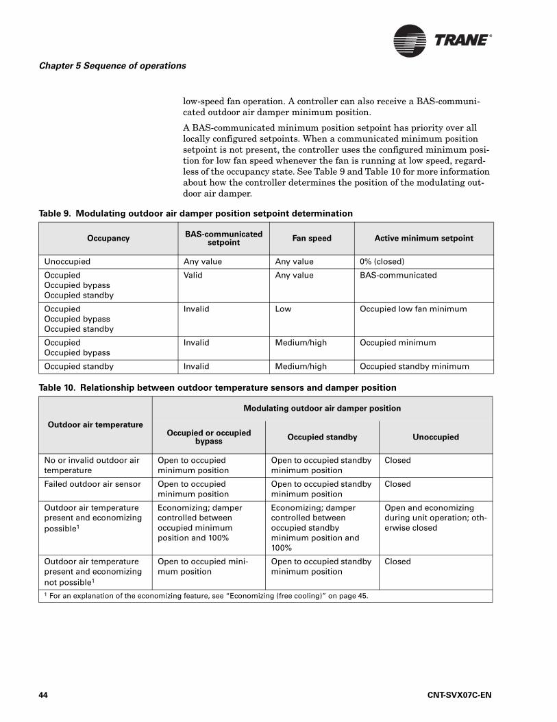
low-speed fan operation. A controller can also receive a BAS-communi-cated outdoor air damper minimum position.
A BAS-communicated minimum position setpoint has priority over all locally configured setpoints. When a communicated minimum position setpoint is not present, the controller uses the configured minimum posi-tion for low fan speed whenever the fan is running at low speed, regard-less of the occupancy state. See Table 9 and Table 10 for more information about how the controller determines the position of the modulating out-door air damper.
Table 9. Modulating outdoor air damper position setpoint determination
OccupancyBAS-communicated
setpointFan speed Active minimum setpoint
Unoccupied Any value Any value 0% (closed)
OccupiedOccupied bypassOccupied standby
Valid Any value BAS-communicated
OccupiedOccupied bypassOccupied standby
Invalid Low Occupied low fan minimum
OccupiedOccupied bypass
Invalid Medium/high Occupied minimum
Occupied standby Invalid Medium/high Occupied standby minimum
Table 10. Relationship between outdoor temperature sensors and damper position
Outdoor air temperature
Modulating outdoor air damper position
Occupied or occupied bypass
Occupied standby Unoccupied
No or invalid outdoor air temperature
Open to occupied minimum position
Open to occupied standby minimum position
Closed
Failed outdoor air sensor Open to occupied minimum position
Open to occupied standby minimum position
Closed
Outdoor air temperature present and economizing possible1
Economizing; damper controlled between occupied minimumposition and 100%
Economizing; damper controlled betweenoccupied standby minimum position and 100%
Open and economizing during unit operation; oth-erwise closed
Outdoor air temperature present and economizing not possible1
Open to occupied mini-mum position
Open to occupied standby minimum position
Closed
1 For an explanation of the economizing feature, see “Economizing (free cooling)” on page 45.
44 CNT-SVX07C-EN

Modulating outdoor/return air dampers
ASHRAE Cycle 1 conformance
Tracer ZN521 applications with an outside air damper support ASHRAE Cycle 1 conformance. ASHRAE Cycle 1 operation admits 100% outdoor air at all times except during a warm-up cycle. A tri-state modulating damper actuator is required for this operation. For Tracer ZN521 ASHRAE Cycle 1 conformance, configure the minimum position of the economizer setpoint to 100% open during occupied periods. If the zone temperature drops 3°F (1.7°C) below the active zone temperature set-point, the Tracer ZN521 closes the outdoor air damper regardless of the minimum position setpoint.
ASHRAE Cycle 2 conformance
Tracer ZN521 controller applications with modulating outside air damper support ASHRAE Cycle 2 conformance. ASHRAE Cycle 2 operation allows the modulating outdoor air damper to completely close when the zone temperature drops 3°F (1.7°C) or more below the active zone temper-ature setpoint. If the zone temperature rises to within 2°F (1.2°C) of the active setpoint, the damper opens to the occupied or occupied standby minimum damper positions. If the zone temperature is between 2°F and 3°F (1.2°C and 1.7°C) below the active zone temperature setpoint, the damper modulates between the minimum position and closed.
If the discharge air temperature is between the discharge air tempera-ture low limit and the discharge air temperature low setpoint, the damper modulates between the minimum position and closed. If this situ-ation is concurrent with ASHRAE Cycle 2 operation, the lesser of the two setpoints will determine the actual damper position.
Economizing (free cooling)
Cooling with outdoor air, when the temperature is low enough to make this possible, is referred to as economizing or free cooling. Tracer ZN521 controller applications with modulating outside air damper support econ-omizing. The modulating outdoor air damper provides the first source of cooling for the Tracer ZN521. The controller initiates economizing if the outdoor air temperature is below the economizer enable point (config-urable using the Rover service tool). If economizing is initiated, the con-troller modulates the outdoor air damper (between the active minimum damper position and 100%) to control the amount of outdoor air cooling capacity. When the outdoor air temperature rises 5°F (2.8°C) above the economizer enable point, the controller disables economizing and moves the outdoor air damper back to its predetermined minimum position based on the current occupancy mode or communicated minimum outdoor air damper position. If an outdoor air temperature value is not present, economizing is disabled.
CNT-SVX07C-EN 45

Chapter 5 Sequence of operations
Two-position control of a modulating
outdoor air damper The Tracer ZN521 does not support a two-position outdoor air damper actuator. However, a modulating outdoor/return air damper actuator can be used for two-position control. Two-position control can be accomplished by not providing an outdoor air temperature (neither hard-wired nor com-municated) to the controller, and by setting the damper minimum posi-tion (using the Rover service tool) to the desired value (typically, 100%).
Face-and-bypass damper operationThe Tracer ZN521 can control a face-and-bypass damper to modulate a percentage of air to the face of the coil(s) and around (bypass) the coil(s) to maintain zone comfort. For two-pipe changeover applications, if the con-troller requests heating and hot water is available, the face-and-bypass damper modulates to the face position. If the controller requests heating and hot water is not available, the face-and-bypass damper remains in the bypass position, and water sampling may be initiated (see “Entering water temperature sampling function” on page 40). For four-pipe changeover applications, both heat and cool capacity are assumed to be available.
Face-and-bypass, isolation-valve operation
A Tracer ZN521 with a face-and-bypass damper controls on/off isolation valve(s) to prevent unwanted water flow through the coil(s) when no air-flow is passing over the coil (100% bypass). In two-pipe applications, the isolation valve stops water flow, preventing radiant heat (heating mode) and excessive condensate (cooling mode) from the coil. In four-pipe appli-cations, the isolation valves are used to prevent simultaneous heating and cooling.
The heating or cooling isolation valve opens whenever capacity is requested (>0%) as the face-and-bypass damper begins to modulate toward the coil face. The isolation valve closes when capacity returns to 0%.
DX cooling operationThe Tracer ZN521 supports one stage of direct expansion (DX) compres-sor operation for cooling only.
Note:
The controller does not use the DX compressor and economizing simultaneously. Not doing so prevents short cycling from occur-ring if the entering air temperature is too low for the evapora-tor coil to operate as designed.
46 CNT-SVX07C-EN

Electric heat operation
Electric heat operationThe Tracer ZN521 supports both single-stage and two-stage electric heat. Electric heat is cycled on and off to maintain the discharge air tempera-ture at the active heating setpoint. Two-pipe changeover units with elec-tric heat use the electric heat only when hot water is not available. The use of both electric and hydronic heat is not supported.
Baseboard heat operationWhen configured for baseboard heat output, the controller turns on base-board heat at 2.2°F (1.2°C) below the active heating setpoint, and turns off baseboard heat at 0.8°F (0.4°C) below the active heating setpoint. The range for activating the baseboard heat cannot be adjusted; however, the heating setpoint is configurable using the Rover service tool.
Baseboard heating is used most effectively when the discharge air tem-perature control high limit is set below 100°F (56°C). If this is done, the unit heat will maintain the temperature on light load days and the base-board heat will be enabled to maintain the temperature on heavier load days.
DehumidificationThe Tracer ZN521 supports a dehumidification feature. Dehumidification is possible if the following are present:
• Mechanical cooling is available• The heating capacity is located in the reheat position• A zone humidity sensor is connected at AI4, or a relative humidity
(RH) value is transmitted to the controller by a BAS.• The Space RH Setpoint is valid (configurable using the Rover service
tool)• Dehumidification is enabled using the Rover service tool
The controller initiates dehumidification if the zone humidity exceeds the humidity setpoint. The controller continues to dehumidify until the sensed humidity falls below the setpoint minus the relative humidity off-set.
The controller uses cooling and heating capacities simultaneously to dehumidify the space. While dehumidifying, the controller maintains the zone temperature at the active setpoint.
Note:
Dehumidification is not available for face-and-bypass applica-tions, and cannot be used if the unit is in the unoccupied mode. Dehumidification disables the economizing function.
CNT-SVX07C-EN 47
Chapter 5 Sequence of operations
Peer-to-peer communicationTracer ZN521 zone controllers have the ability to share data with other LonTalk-based controllers. Multiple controllers can be bound as peers, using the Rover service tool, to share:
• Setpoint• Zone temperature• Heating/cooling mode• Fan status• Unit capacity control
Shared data is communicated from one controller to any other controller that is bound to it as a peer. Applications having more than one unit serv-ing a single zone can benefit by using this feature; it allows multiple units to share a single zone temperature sensor and prevents multiple units from simultaneously heating and cooling.
Unit protection strategiesThe following strategies are initiated when specific conditions exist in order to protect the unit or building from damage:
• Smart reset• Low-coil-temperature protection• Condensate overflow• Fan status• Fan off delay• Filter-maintenance timer• Freeze avoidance• Freeze protection (discharge air temperature low limit)
48 CNT-SVX07C-EN

Unit protection strategies
Smart reset
The Tracer ZN521 will automatically restart a unit that is locked-out as a result of a Low Coil Temp Detection (BI1) diagnostic. Referred to as “smart reset,” this automatic restart will occur 30 minutes after the diag-nostic occurs. If the unit is successfully restarted, the diagnostic is cleared. If the unit undergoes another Low Coil Temp Detection diagnos-tic within a 24-hour period, the unit will be locked out until it is manually reset. (For more information on manual resetting, see “Manual (latching) diagnostics” on page 58).
Low-coil-temperature protection
See “BI1: Low-coil-temperature detection” on page 14 and “Smart reset” above.
Condensate overflow
See “BI2: Condensate overflow” on page 14.
Fan status
The fan status is based on the status of the binary output(s) dedicated to fan control. The fan status is reported as high, medium, or low whenever the corresponding binary output is energized. The fan status is reported as off whenever none of the fan binary outputs are energized.
Additionally, a fan-status switch can be connected to BI4 to monitor the status of the fan for belt-driven or direct-driven units. The fan status switch provides feedback to the controller. If the fan is not operating when the controller has the fan controlled to on, the controller will generate a Low AirFlow—Fan Failure diagnostic.
If the controller energizes the fan output for 1 minute, and the fan status switch indicates no fan operation, the controller performs a unit shut-down and generates a Low AirFlow—Fan Failure diagnostic. If the fan has been operating normally for one minute, but the fan status switch indicates no fan operation, the same diagnostic is generated. This manual diagnostic discontinues unit operation until the diagnostic has been cleared from the controller. If a diagnostic reset is sent to the controller and the fan condition still exists, the controller attempts to run the fan for 1 minutes before generating another diagnostic and performing a unit shutdown.
Fan off delay
After heating has been controlled off, the Tracer ZN521 keeps the fan energized for an additional 30 seconds. The purpose of this feature is to remove residual heat from the heating source.
CNT-SVX07C-EN 49
Chapter 5 Sequence of operations
Filter-maintenance timer
The filter-maintenance timer tracks the amount of time (in hours) that the fan is enabled. The Maintenance Required Timer Setpoint (config-urable using the Rover service tool) is used to set the amount of time until maintenance (typically, a filter change) is needed. If the setpoint is config-ured to zero, the filter-maintenance timer is disabled.
The controller compares the fan-run time to Maintenance Required Timer Setpoint. Once the setpoint is reached, the controller generates a Mainte-nance Required diagnostic. When the diagnostic is cleared, the controller resets the filter-maintenance timer to zero, and the timer begins accumu-lating fan-run time again.
Freeze avoidance
Freeze avoidance is used for low ambient temperature protection. It is ini-tiated only when the fan is off. The controller enters the freeze-avoidance mode when the outdoor air temperature is below the Freeze Avoidance Setpoint (configurable using the Rover service tool). The controller dis-ables freeze avoidance when the outdoor air temperature rises 3°F (1.7°C) above the Freeze Avoidance Setpoint.
When the controller is in freeze-avoidance mode:
• Valves are driven open to allow water to flow through the coil• Fan is off• Face-and-bypass damper (when present) is at full bypass• Economizing is disabled• The outdoor/return air damper is closed• DX cooling is off• Electric heat stages are off
Freeze protection (discharge air temperature low limit)
The controller monitors the discharge air temperature with a 10 kΩ ther-mistor wired to analog input AI2. The freeze-protection operation is initi-ated whenever the discharge air temperature falls below the Discharge Air Temperature Low Limit. The Discharge Air Temperature Low Limit is configurable using the Rover service tool. During freeze protection, the controller increases the heating capacity or decreases the cooling capacity in order to raise the discharge air temperature above the low limit. If the discharge air temperature remains below the low limit for 3 minutes, the controller generates a Discharge Air Temp Limit diagnostic. See Table 16 on page 59 for the effects of this diagnostic on outputs.
50 CNT-SVX07C-EN
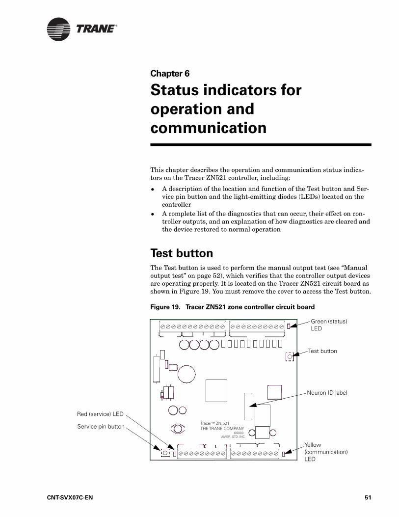
Chapter 6
Status indicators for
operation and
communication
This chapter describes the operation and communication status indica-tors on the Tracer ZN521 controller, including:
• A description of the location and function of the Test button and Ser-vice pin button and the light-emitting diodes (LEDs) located on the controller
• A complete list of the diagnostics that can occur, their effect on con-troller outputs, and an explanation of how diagnostics are cleared and the device restored to normal operation
Test buttonThe Test button is used to perform the manual output test (see “Manual output test” on page 52), which verifies that the controller output devices are operating properly. It is located on the Tracer ZN521 circuit board as shown in Figure 19. You must remove the cover to access the Test button.
Figure 19. Tracer ZN521 zone controller circuit board
Green (status) LED
Test button
Neuron ID label
Yellow (communication) LED
Red (service) LED
Service pin button
CNT-SVX07C-EN 51

Chapter 6 Status indicators for operation and communication
Manual output testThe manual output test sequentially turns on and off all binary outputs to verify their operation. The test overrides normal operation of the con-troller, which is suspended while the test is being performed.
Use the manual output test to:
• Verify output wiring and operation• Force the water valve(s) open to balance the hydronic system• Clear diagnostics and restore normal operation (although not a pri-
mary function of the manual output test)
The manual output test is performed either by repeatedly pressing the Test button to proceed through the test sequence or by using the Rover service tool. Table 11 on page 53 lists the outputs for non-face-and-bypass unit configurations in the sequence in which they are verified; Table 12 on page 55 lists the outputs for face-and-bypass unit configurations in the sequence in which they are verified.
The procedure is as follows:
1. Press and hold the Test button for 3 to 4 seconds, then release it to start the test mode. The green (status) LED goes off when you press the Test button, and then it blinks (as described in Table 14 on page 57) when the Test button is released to indicate that the control-ler is in manual test mode.
2. Press the Test button (no more than once per second) to advance through the test sequence. Table 11 and Table 12 show the resulting activities of the binary outputs.
Note:
The outputs are not subject to minimum on or off times during the test sequence.
52 CNT-SVX07C-EN

Manual output test
Table
11.
Man
ual
ou
tpu
t te
st
se
qu
en
ce f
or
no
n-f
ace-a
nd
-byp
ass c
on
fig
ura
tio
ns
Ste
pR
esu
ltB
OP
1B
OP
2B
OP
3B
OP
4B
OP
5B
OP
6B
OP
7B
OP
8B
OP
9B
OP
10
Number of times Test button is pressed
Fan high
1)Fan medium
2)Exhaust
Fan low
1)Cooling/changeover valve, open
2)Two-position cooling/changeover valve
3)DX compressor
Cooling/changeover valve, close
1)Heating valve, open
2)Two-position heat valve
3)Electric heat, stage 1
1)Heating valve, close
2)Electric heat, stage 2
Outdoor air damper, open
Outdoor air damper, close
1)Generic
2)Baseboard heat
1B
egin
s te
st
mo
de1
Off
Off
Off
Off
On/C
lose
Off
1)
On
/Clo
se2)
Off
Off
On
/Clo
seO
ff
2Fa
n h
igh
2O
n/H
igh
Off
Off
Off
Off
Off
Off
Off
Off
Off
3Fa
n
med
ium
3O
ff1
) O
n/M
ed2
) O
ffO
ffO
ffO
ffO
ffO
ffO
ffO
ffO
ff
4Fa
n lo
w4
Off
Off
On
/Low
Off
Off
Off
Off
Off
Off
Off
5M
ain
op
en,
DX
on
On
/Hig
hO
ffO
ffO
n/O
pen
Off
Off
Off
Off
Off
Off
6M
ain
clo
se,
DX
off
, au
x o
pen
, EH
1 o
n
On
/Hig
hO
ffO
ffO
ffO
n/C
lose
On
/Op
enO
ffO
ffO
ffO
ff
7A
ux
op
en,
EH
1 o
n,
exh
aust
fa
n5
On
/Hig
h1
) O
ff2
) O
nO
ffO
ffO
ffO
n/O
pen
Off
Off
Off
Off
8A
ux
clo
se,
EH
1 o
ff,
EH
2 o
n,
dam
per
o
pen
On
/Hig
hO
ffO
ffO
ffO
ffO
ffO
n/C
lose
On
/Op
enO
ffO
ff
9D
amp
er
clo
seO
n/H
igh
Off
Off
Off
Off
Off
Off
Off
On
/Clo
seO
ff
10G
ener
ic/
bas
ebo
ard
h
eat
ener
giz
ed6
On
/Hig
hO
ffO
ffO
ffO
ffO
ffO
ffO
ffO
ffO
n
CNT-SVX07C-EN 53

Chapter 6 Status indicators for operation and communication
11: E
xit5
1T
he
con
tro
ller
turn
s o
ff a
ll fa
n a
nd
ele
ctri
c h
eat
ou
tpu
ts a
nd
dri
ves
all d
amp
ers
and
val
ves
clo
sed
.2
Th
e co
ntr
olle
r at
tem
pts
to
cle
ar a
ll d
iag
no
stic
s.3
If c
on
fig
ure
d f
or
a 3-
spee
d f
an, t
he
med
ium
fan
sp
eed
ou
tpu
t w
ill e
ner
giz
e at
ste
p 3
. If
con
fig
ure
d f
or
a 2-
spee
d f
an, t
he
fan
rem
ain
s o
n h
igh
sp
eed
at
step
3.
4If
co
nfi
gu
red
fo
r a
3-sp
eed
fan
, th
e m
ediu
m f
an s
pee
d o
utp
ut
ener
giz
es a
t st
ep 4
. If
con
fig
ure
d f
or
a 2-
spee
d f
an, t
he
low
fan
sp
eed
ou
tpu
t en
erg
izes
at
step
4. I
f co
nfi
gu
red
fo
r a
1-sp
eed
fan
, th
e fa
n r
emai
ns
on
hig
h s
pee
d a
t st
ep 4
.5
If t
he
un
it is
co
nfi
gu
red
fo
r a
1- o
r 2-
spee
d f
an, t
he
exh
aust
fan
ou
tpu
t en
erg
izes
on
ste
p 7
. Th
e ex
hau
st f
an o
utp
ut
is s
har
ed w
ith
med
ium
fan
sp
eed
.6
Aft
er s
tep
10,
th
e m
anu
al o
utp
ut
test
per
form
s an
exi
t, w
hic
h in
itia
tes
a re
set
to r
esto
re t
he
con
tro
ller
to n
orm
al o
per
atio
n.
Tab
le 1
1.
Man
ual
ou
tpu
t te
st
se
qu
en
ce f
or
no
n-f
ace-a
nd
-byp
ass c
on
fig
ura
tio
ns
Ste
pR
esu
ltB
OP
1B
OP
2B
OP
3B
OP
4B
OP
5B
OP
6B
OP
7B
OP
8B
OP
9B
OP
10
Number of times Test button is pressed
Fan high
1)Fan medium
2)Exhaust
Fan low
1)Cooling/changeover valve, open
2)Two-position cooling/changeover valve
3)DX compressor
Cooling/changeover valve, close
1)Heating valve, open
2)Two-position heat valve
3)Electric heat, stage 1
1)Heating valve, close
2)Electric heat, stage 2
Outdoor air damper, open
Outdoor air damper, close
1)Generic
2)Baseboard heat
54 CNT-SVX07C-EN
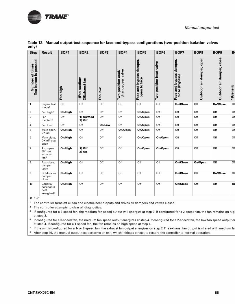
Manual output test
BO
1)G
en
eri
c
e Off
Off
Off
Off
Off
Off
Off
Off
e Off
On
s on high
utput en
dium fan
Table 12. Manual output test sequence for face-and-bypass configurations (two-position isolation valves only)
Step Result BOP1 BOP2 BOP3 BOP4 BOP5 BOP6 BOP7 BOP8 BOP9
Nu
mb
er
of
tim
es
Test
bu
tto
n i
s p
resse
d
Fan
hig
h
1)F
an
me
diu
m
2)E
xh
au
st
fan
Fan
lo
w
Tw
o-p
osit
ion
co
ol/
ch
an
ge
ove
r valv
e
Face a
nd
byp
ass d
am
pe
r,
op
en
to
fa
ce
Tw
o-p
osit
ion
he
at
va
lve
Face a
nd
byp
ass d
am
pe
r,clo
se (
by
pass)
Ou
tdo
or
air
da
mp
er,
op
en
Ou
tdo
or
air
dam
pe
r, c
lose
1 Begins test mode1
Off Off Off Off Off Off On/Close Off On/Clos
2 Fan high2 On/High Off Off Off On/Open Off Off Off Off
3 Fan medium3
Off 1) On/Med2) Off
Off Off On/Open Off Off Off Off
4 Fan low4 Off Off On/Low Off On/Open Off Off Off Off
5 Main open, DX on
On/High Off Off On/Open On/Open Off Off Off Off
6 Main close, DX off, aux open
On/High Off Off Off On/Open On/Open Off Off Off
7 Aux open, EH1 on, exhaust fan5
On/High 1) Off2) On
Off Off On/Open On/Open Off Off Off
8 Aux close, damper open
On/High Off Off Off Off Off On/Close On/Open Off
9 Outdoor air damper close
On/High Off Off Off Off Off On/Close Off On/Clos
10 Generic/baseboard heat energized6
On/High Off Off Off Off Off On/Close Off Off
11: Exit5
1 The controller turns off all fan and electric heat outputs and drives all dampers and valves closed.2 The controller attempts to clear all diagnostics.3 If configured for a 3-speed fan, the medium fan speed output will energize at step 3. If configured for a 2-speed fan, the fan remain
at step 3.4 If configured for a 3-speed fan, the medium fan speed output energizes at step 4. If configured for a 2-speed fan, the low fan speed o
at step 4. If configured for a 1-speed fan, the fan remains on high speed at step 4.5 If the unit is configured for a 1- or 2-speed fan, the exhaust fan output energizes on step 7. The exhaust fan output is shared with me6 After step 10, the manual output test performs an exit, which initiates a reset to restore the controller to normal operation.
CNT-SVX07C-EN 55

Chapter 6 Status indicators for operation and communication
Service pin buttonThe Service pin button is located as shown in Figure 19 on page 51. The Service pin button is used to:
• Identify a device (see “Identifying a device” in the Rover Installation/Operation/Programming guide (EMTX-SVX01A-EN)
• Add a device to the active group (see “Adding a device” in EMTX-SVX01A-EN)
• Verify PCMCIA communications (see “Verifying PCMCIA communi-cations” in EMTX-SVX01A-EN)
• Make the green (status) LED “wink” to verify that the controller is communicating on the link (see Table 14 on page 57 and “Setting the Auto-wink option” in EMTX-SVX01A-EN)
Interpreting LEDsThe red (service) LED on the Tracer ZN521 controller (see Figure 19 on page 51) indicates whether the controller is capable of operating normally (see Table 13).
Table 13. Red LED: Service indicator
LED activity Explanation
LED is off continuously when power is applied to the controller.
The controller is operating normally.
LED is on continuously when power is applied to the controller.
The controller is not working prop-erly, or someone is pressing the Ser-vice pin button.
LED flashes once every second. The controller is not executing the application software because the net-work connections and addressing have been removed.1
1 Restore the controller to normal operation using the Rover service tool. Refer to EMTX-SVX01A-EN for more information.
56 CNT-SVX07C-EN

Interpreting LEDs
The green (status) LED on the Tracer ZN521 controller (see Figure 19 on page 51) indicates whether the controller has power applied to it and if the controller is in manual test mode (see Table 14).
The yellow (communications) LED on the Tracer ZN521 controller (see Figure 19 on page 51) indicate the controller’s communication status (see Table 15).
Table 14. Green LED: Status indicator
LED activity Explanation
LED is on continuously. Power is on (normal operation).
LED blinks (one recurring blink). Manual output test mode is being performed and no diagnostics are present.
LED blinks (blinks twice as a recur-ring sequence).
Manual output test mode is being performed and one or more diag-nostics are present.
LED blinks (1/4 second on, 1/4 second off for 10 seconds).
The Auto-wink option is activated, and the controller is communicating.1
LED is off continuously. Either the power is off, the controller has malfunctioned, or the Test button is being pressed.
1 By sending a request from the Rover service tool, you can request the controller’s green LED to blink (“wink”), a notification that the controller received the signal and is communicating.
Table 15. Yellow LED: Communications indicator
LED activity Explanation
LED is off continuously The controller is not detecting any communication (normal for stand-alone applications).
LED blinks. The controller detects communica-tion (normal for communicating applications, including data sharing).
LED is on continuously. Problem with communication link wiring (possible need for termination resistor), or controller failure (caused by power surge, lightning strike, etc.)
CNT-SVX07C-EN 57

Chapter 6 Status indicators for operation and communication
Diagnostics Diagnostics are informational messages that indicate the operational sta-tus of the controller. In response to most diagnostics, the controller attempts to protect the equipment by enabling or disabling, or opening or closing, specific outputs. Other diagnostics provide information about the status of the controller, but have no effect on outputs. Diagnostics are reported in the order in which they occur. Multiple diagnostics can be present simultaneously. Diagnostic messages are viewed using the Rover service tool or through a BAS.
Types of diagnostics
Diagnostics are categorized according to the type of clearing method each uses and the type of information each provides.
The four categories are:
• Manual (latching)• Automatic (nonlatching)• Smart reset • Informational
Manual (latching) diagnostics
Manual diagnostics (also referred to as latching) cause the unit to shut down. Manual diagnostics can be cleared from the controller in one of the following ways:
• By using the Rover service tool (see “Resetting a diagnostic” in EMTX-SVX01A-EN, Rover Installation/Operation/and Program-ming guide).
• Through a building automation system (see product literature)• By initiating a manual output test at the controller (see “Manual out-
put test” on page 52)• By cycling power to the controller. When the 24 Vac power to the con-
troller is cycled off and then on again, a power-up sequence occurs.• By turning the zone sensor fan switch to OFF and then back to any
other setting. (This feature will be available beginning with controller software version 2.10.)
Automatic (nonlatching) diagnostics
Automatic diagnostics clear automatically when the problem that gener-ated the diagnostic is solved.
Note:
Clearing diagnostics refers to deleting diagnostics from the software; it does not affect the problem that generated the mes-sage. For help with diagnosing a problem, see Chapter 7, “Trou-bleshooting”.
58 CNT-SVX07C-EN

Diagnostics
Smart reset diagnostics
After the controller detects the first smart reset diagnostic, the unit waits 30 minutes before initiating the smart reset function. If another diagnos-tic of this type occurs again within 24 hours after an automatic clearing, you must clear the diagnostic manually by using any of the ways shown for “Manual (latching) diagnostics.”
Informational diagnostics
Informational diagnostics provide information about the status of the controller. They do not affect machine operation. They can be cleared from the controller using any of the ways shown for “Manual (latching) diag-nostics.”
Table of diagnostics
Table 16 The tables present each diagnostic that can be generated by the Tracer ZN521, its effect on outputs (consequences), and its type.
Note:
The generic binary output is unaffected by diagnostics.
Table 16. Diagnostics
Diagnostic Probable cause ConsequencesDiagnostic
type
Maintenance Required Fan run hours exceed the time set to indicate filter change
Fan unaffectedValves unaffectedElectric heat unaffectedFace and bypass damper unaffected
Informational
Condensate Overflow The drain pan is full of water
Fan offValves closedOutdoor air damper closedFace and bypass damper bypassDX/electric heat offBaseboard heat off
Manual
Low Coil Temp Detection The leaving fluid temper-ature may be close to freezing
Fan offValves openOutdoor air damper closedFace and bypass damper bypassDX/electric heat offBaseboard heat off
Smart reset/Manual
Low Airflow—Fan Failure The fan drive belt, con-tactor, or motor has failed.
Fan offValves closedOutdoor air damper closedFace and bypass damper bypassDX/electric heat offBaseboard heat off
Manual
CNT-SVX07C-EN 59

Chapter 6 Status indicators for operation and communication
Space Temperature Failure Invalid or missing value for zone temperature
Fan offValves closedOutdoor air damper closedFace and bypass damper bypassDX/electric heat offBaseboard heat off
Automatic
Entering Water Temp Failure Invalid or missing value for zone temperature
Fan unaffected (enabled)Valves unaffectedOutdoor air damper unaffectedFace and bypass damper unaffectedDX/electric heat unaffectedBaseboard heat off
Automatic
Discharge Air Temp Limit Discharge air tempera-ture has fallen below the Discharge Air Tempera-ture Low Limit
Fan offValves openOutdoor air damper closedFace and bypass damper bypassDX/electric heat offBaseboard heat off
Automatic
Discharge Air Temp Failure Invalid or missing value for discharge air temper-ature
Fan offValves closedOutdoor air damper closedFace and bypass damper bypassDX cooling/electric heat offBaseboard heat off
Automatic
Outdoor Air Temp Failure Invalid or missing value for outdoor air tempera-ture
Fan unaffectedValved unaffectedOutdoor air damper minimum positionFace and bypass damper unaffectedDX cooling/electric heat unaffectedBaseboard heat unaffected
Automatic
Humidity Input Failure Invalid or missing value for relative humidity
Fan unaffectedValves unaffectedOutdoor air damper unaffectedFace and bypass damper unaffectedDX cooling/electric heat unaffectedBaseboard heat unaffectedDehumidification sequence off
Automatic
CO2 Sensor Failure Invalid or missing value for CO2
Fan unaffectedValves unaffectedOutdoor air damper unaffectedFace and bypass damper unaffectedDX cooling/electric heat unaffectedBaseboard heat unaffected
Informational
Table 16. Diagnostics (Continued)
Diagnostic Probable cause ConsequencesDiagnostic
type
60 CNT-SVX07C-EN

Diagnostics
Generic AIP Failure Invalid or missing value for generic analog input
Fan unaffectedValves unaffectedOutdoor air damper unaffectedFace and bypass damper unaffectedDX cooling/electric heat unaffectedBaseboard heat unaffected
Informational
Local Fan Mode Failure Invalid or missing fan-speed switch (reverts to default fan speed)
Fan unaffectedValves unaffectedOutdoor air damper unaffectedFace and bypass damper unaffectedDX cooling/electric heat unaffectedBaseboard heat unaffected
Automatic
Local Setpoint Failure Invalid or missing value for zone temperature set-point (reverts to default setpoint)
Fan unaffectedValves unaffectedOutdoor air damper unaffectedFace and bypass damper unaffectedDX cooling/electric heat unaffectedBaseboard heat unaffected
Automatic
Generic Temperature Failure Invalid or missing generic temperature value
Fan unaffectedValves unaffectedOutdoor air damper unaffectedFace and bypass damper unaffectedDX cooling/electric heat unaffectedBaseboard heat unaffected
Informational
Invalid Unit Configuration Software is configured improperly
Fan offValves offOutdoor air damper closedFace and bypass damper closedDX cooling/electric heat offBaseboard heat off
Manual
Normal On start-up Fan unaffectedValves unaffectedElectric heat unaffectedCompressors unaffectedDamper unaffected
Automatic
Table 16. Diagnostics (Continued)
Diagnostic Probable cause ConsequencesDiagnostic
type
CNT-SVX07C-EN 61

Chapter 6 Status indicators for operation and communication
62 CNT-SVX07C-EN
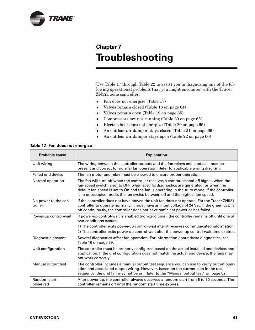
Chapter 7
Troubleshooting
Use Table 17 through Table 22 to assist you in diagnosing any of the fol-lowing operational problems that you might encounter with the Tracer ZN521 zone controller:
• Fan does not energize (Table 17)• Valves remain closed (Table 18 on page 64)• Valves remain open (Table 19 on page 65)• Compressors are not running (Table 20 on page 65)• Electric heat does not energize (Table 20 on page 65)• An outdoor air damper stays closed (Table 21 on page 66)• An outdoor air damper stays open (Table 22 on page 66)
Table 17. Fan does not energize
Probable cause Explanation
Unit wiring The wiring between the controller outputs and the fan relays and contacts must be present and correct for normal fan operation. Refer to applicable wiring diagram.
Failed end device The fan motor and relay must be checked to ensure proper operation.
Normal operation The fan will turn off when the controller receives a communicated off signal, when the fan-speed switch is set to OFF, when specific diagnostics are generated, or when the default fan speed is set to Off and the fan is operating in the Auto mode. If the controller is in unoccupied mode, the fan cycles between off and the highest fan speed.
No power to the con-troller
If the controller does not have power, the unit fan does not operate. For the Tracer ZN521 controller to operate normally, it must have an input voltage of 24 Vac. If the green LED is off continuously, the controller does not have sufficient power or has failed.
Power-up control-wait If power-up control-wait is enabled (non-zero time), the controller remains off until one of two conditions occurs:1) The controller exits power-up control-wait after it receives communicated information.2) The controller exits power-up control-wait after the power-up control-wait time expires.
Diagnostic present Several diagnostics affect fan operation. For information about these diagnostics, see Table 16 on page 59.
Unit configuration The controller must be properly configured based on the actual installed end devices and application. If the unit configuration does not match the actual end device, the fans may not work correctly.
Manual output test The controller includes a manual output test sequence you can use to verify output oper-ation and associated output wiring. However, based on the current step in the test sequence, the unit fan may not be on. Refer to the “Manual output test” on page 52.
Random start observed
After power-up, the controller always observes a random start from 5 to 30 seconds. The controller remains off until the random start time expires.
CNT-SVX07C-EN 63

Chapter 7 Troubleshooting
Cycling fan operation/continuous
The controller operates the fan continuously when in the occupied, occupied standby, or occupied bypass mode. When the controller is in the unoccupied mode, the fan is cycled between high speed and off with capacity.
Unoccupied operation Even if the controller is configured for continuous fan operation, the fan normally cycles with capacity during unoccupied mode. While unoccupied, the fan cycles on or off with heating/cooling to provide varying amounts of heating or cooling to the space.
Fan mode off If a local fan mode switch determines the fan operation, the off position controls the fan off.
Requested mode off You can communicate a desired operating mode (such as off, heat, and cool) to the con-troller. If off is communicated to the controller, the unit controls the fan off. There is no heating or cooling.
Table 18. Valves remain closed
Probable cause Explanation
Unit wiring The wiring between the controller outputs and the valve(s) must be present and correct for normal valve operation. Refer to applicable wiring diagram.
Failed end device The valves must be checked to ensure proper operation.
No power to the con-troller
If the controller does not have power, the unit valve(s) will not operate. For the Tracer ZN521 controller to operate normally, you must apply an input voltage of 24 Vac. If the green LED is off continuously, the controller does not have sufficient power or has failed.
Power-up control-wait If power-up control-wait is enabled (non-zero time), the controller remains off until one of two conditions occurs:1) The controller exits power-up control-wait after it receives communicated information.2) The controller exits power-up control-wait after the power-up control-wait time expires.
Diagnostic present Several diagnostics affect valve operation. For information about these diagnostics, see Table 16 on page 59.
Normal operation The controller opens and closes the valves to meet the unit capacity requirements.
Unit configuration The controller must be properly configured based on the actual installed end devices and application. If the unit configuration does not match the actual end device, the valves may not work correctly.
Manual output test The controller includes a manual output test sequence you can use to verify output oper-ation and associated output wiring. However, based on the current step in the test sequence, the valves may not be open. Refer to the “Manual output test” on page 52.
Random start observed
After power-up, the controller always observes a random start from 5 to 30 seconds. The controller remains off until the random start time expires.
Requested mode off You can communicate a desired operating mode (such as off, heat, and cool) to the con-troller. If off is communicated to the controller, the unit controls the fan off. There is no heating or cooling.
Entering water temperature sampling logic
The controller includes entering water temperature sampling logic, which is automati-cally initiated during 2-pipe and 4-pipe changeover if the entering water temperature is either too cool or too hot for the desired heating or cooling. (See “AI1: Entering water temperature” on page 17.)
Valve configuration Make sure the valves are correctly configured, using the Rover service tool, as normally open or normally closed as dictated by the application.
Table 17. Fan does not energize (Continued)
Probable cause Explanation
64 CNT-SVX07C-EN

Troubleshooting
Table 19. Valves remain open
Probable cause Explanation
Unit wiring The wiring between the controller outputs and the valve(s) must be present and correct for normal valve operation. Refer to applicable wiring diagram.
Failed end device The valves must be checked to ensure proper operations.
Normal operation The controller opens and closes the valves to meet the unit capacity requirements.
Manual output test The controller includes a manual output test sequence you can use to verify output oper-ation and associated output wiring. However, based on the current step in the test sequence, the values may not be open. refer to the “Manual output test” on page 52.
Diagnostic present Several diagnostics affect valve operation. For information about these diagnostics, see Table 16 on page 59.
Unit configuration The controller must be properly configured based on the actual installed end devices and application. If the unit configuration does not match the actual end device, the valves may not work correctly.
Entering water temperature sampling logic
The controller includes entering water temperature sampling logic, which is automatically initiated during 2-pipe and 4-pipe changeover if the entering water temperature is either too cool or too hot for the desired heating or cooling. (See “AI1: Entering water tempera-ture” on page 17.)
Valve configuration Make sure the valves are correctly configured, using the Rover service tool, as normally open or normally closed as dictated by the application.
Freeze avoidance When the fan is off with no demand for capacity (0%) and the outdoor air temperature is below the freeze avoidance setpoint, the controller opens the water valves (100%) to pre-vent coil freezing. This includes unoccupied mode when there is no call for capacity or any other time the fan is off.
Table 20. DX or electric heat does not energize
Probable cause Explanation
Unit wiring The wiring between the controller outputs and the end devices must be present and cor-rect for normal operation. Refer to applicable wiring diagram.
Failed end device Check the control contactors or the electric heat element, including any auxiliary safety interlocks, to ensure proper operation.
No power to the controller
If the controller does not have power, heat outputs do not operate. For the Tracer ZN521 controller to operate normally, you must apply an input voltage of 24 Vac. If the green LED is off continuously, the controller does not have sufficient power or has failed.
Diagnostic present Several diagnostics affect DX and electric heat operation. For information about these diagnostics, see Table 16 on page 59.
Normal operation The controller controls compressor or electric heat outputs as needed to meet the unit capacity requirements.
Unit configuration
The controller must be properly configured based on the actual installed end devices and application. If the unit configuration does not match the actual end device, DX or electric heat may not operate correctly.
Manual output test The controller includes a manual output test sequence you can use to verify output oper-ation and associated output wiring. However, based on the current step in the test sequence, the DX or electric heat outputs may be off. Refer to the “Manual output test” on page 52.
CNT-SVX07C-EN 65

Chapter 7 Troubleshooting
Requested mode off You can communicate a desired operating mode (such as off, heat, and cool) to the con-troller. If off is communicated to the controller, the unit shuts off the compressor or elec-tric heat.
Freeze avoidance When the fan is off with no demand for capacity (0%) and the outdoor air temperature is below the freeze avoidance setpoint, the controller disables compressors and electric heat outputs (100%) to prevent coil freezing. This includes unoccupied mode when there is no call for capacity or any other time the fan is off.
Table 21. Outdoor air damper remains closed
Probable cause Explanation
Unit wiring The wiring between the controller outputs and the outdoor air damper must be present and correct for normal outdoor air damper operation. Refer to applicable wiring diagram.
Failed end device Check damper actuator to ensure proper operation.
No power to the controller
If the controller does not have power, the outdoor air damper does not operate. For the Tracer ZN521 controller to operate normally, you must apply an input voltage of 24 Vac. If the green LED is off continuously, the controller does not have sufficient power or has failed.
Diagnostic present Several diagnostics affect outdoor air damper operation. For information about these diagnostics, see Table 16 on page 59.
Normal operation
The controller opens and closes the outdoor air damper based on the controller’s occu-pancy mode and fan status. Normally, the outdoor air damper is open during occupied mode when the fan is running and closed during unoccupied mode.
Unit configuration The controller must be properly configured based on the actual installed end devices and application. If the unit configuration does not match the actual end device, the outdoor air damper may not work correctly.
Manual output test The controller includes a manual output test sequence you can use to verify output oper-ation and associated output wiring. However, based on the current step in the test sequence, the outdoor air damper may not be open. Refer to the “Manual output test” on page 52.
Warm-up and cool-down sequence
The controller includes both a morning warm-up and cool-down sequence to keep the outdoor air damper closed during the transition from unoccupied to occupied. This is an attempt to bring the space under control as quickly as possible.
Requested mode off You can communicate a desired operating mode (such as off, heat, or cool) to the control-ler. If off is communicated to the controller, the unit closes the outdoor air damper.
Table 22. Outdoor air damper remains open
Probable cause Explanation
Unit wiring The wiring between the controller outputs and the outdoor air damper must be present and correct for normal outdoor air damper operation. Refer to applicable wiring diagram.
Failed end device Check damper actuator to ensure proper operation.
Table 20. DX or electric heat does not energize (Continued)
Probable cause Explanation
66 CNT-SVX07C-EN
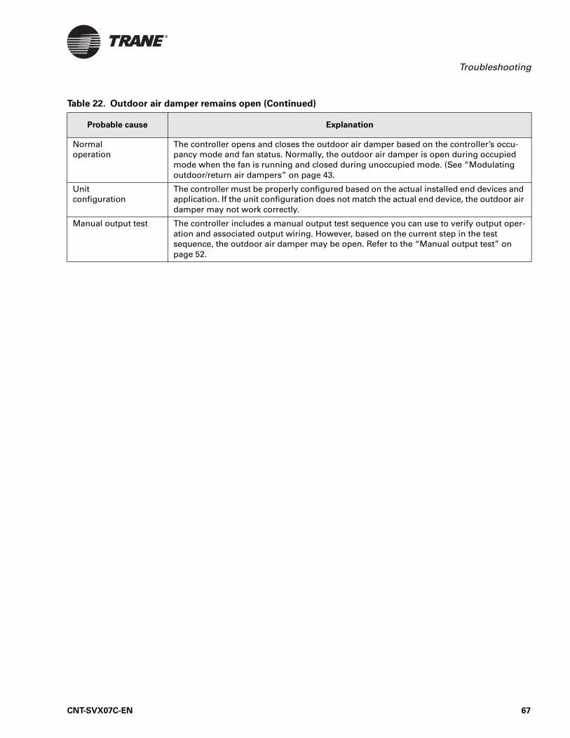
Troubleshooting
Normal operation
The controller opens and closes the outdoor air damper based on the controller’s occu-pancy mode and fan status. Normally, the outdoor air damper is open during occupied mode when the fan is running and closed during unoccupied mode. (See “Modulating outdoor/return air dampers” on page 43.
Unit configuration
The controller must be properly configured based on the actual installed end devices and application. If the unit configuration does not match the actual end device, the outdoor air damper may not work correctly.
Manual output test The controller includes a manual output test sequence you can use to verify output oper-ation and associated output wiring. However, based on the current step in the test sequence, the outdoor air damper may be open. Refer to the “Manual output test” on page 52.
Table 22. Outdoor air damper remains open (Continued)
Probable cause Explanation
CNT-SVX07C-EN 67

Chapter 7 Troubleshooting
68 CNT-SVX07C-EN

CNT-SVX07C-EN
Index
Numerics
24 Vac wiring, 7
A
AC-power wiring, 7
ActuatorsDamper, 5, 46Valve, 4
Additional application-dependent components, 4–5
AddressingLonTalk communication, 9Neuron IDs, 9
Agency listing/compliance, 3
Analog inputs, 16–20AI1 (Entering water temperature),
17AI2 (Discharge air temperature), 18AI3 (Outdoor air temperature), 18AI3 configuration options, 18AI4 (Universal 4–20 mA), 19AI4 configuration options, 19AI4 configured for CO2
measurement, 20AI4 configured for RH
measurement, 20AI4 generic configuration, 19FAN (Fan mode input), 17Generic temperature, 18SET (Local setpoint), 17ZN (Zone temperature), 16
Applications, 1, 13–34
Applications table, 13
ASHRAE Cycle 1Agency listing/compliance, 4Operation, 45
ASHRAE Cycle 2Agency listing/compliance, 4Operation, 45
B
BAS communication, 1, 9
Baseboard heatOperation, 47Supported application, 21
Binary inputs, 14–15BI1 (Low-coil-temperature
detection), 14BI2 (Condensate overflow), 14BI3 (Occupancy or generic), 15BI3 configuration options, 15BI4 (Fan status), 15Switching devices, 4
Binary outputs, 21–22Generic, 21Manual output test, 52Output devices, 4Overriding, 22Table of supported options, 21
Blower coils, 1, 21
Building automation system communication, 1, 9
C
CE, see Agency listing/compliance
Circuit board, 51
Clearances, 2
Clearing diagnostics, 58
CO2Measurement input, 20Sensor, 5, 20Sensor failure diagnostic, 60
Condensate overflowDiagnostic, 59Input, 14Switch, 4, 14
Configuration optionsAI3 (Outdoor air temperature or
generic), 18AI4 (Generic, CO2 measurement, or
RH measurement), 19BI3 (Occupancy or generic), 15DX cooling, 1
39
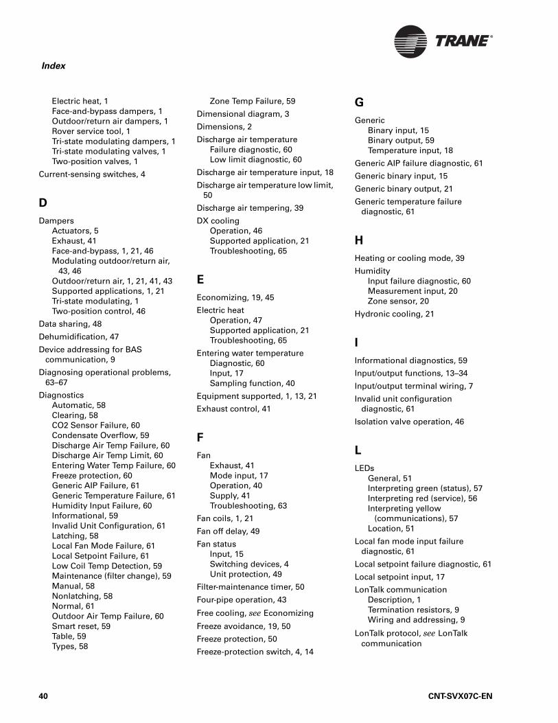
Index
Electric heat, 1Face-and-bypass dampers, 1Outdoor/return air dampers, 1Rover service tool, 1Tri-state modulating dampers, 1Tri-state modulating valves, 1Two-position valves, 1
Current-sensing switches, 4
D
DampersActuators, 5Exhaust, 41Face-and-bypass, 1, 21, 46Modulating outdoor/return air,
43, 46Outdoor/return air, 1, 21, 41, 43Supported applications, 1, 21Tri-state modulating, 1Two-position control, 46
Data sharing, 48
Dehumidification, 47
Device addressing for BAS communication, 9
Diagnosing operational problems, 63–67
DiagnosticsAutomatic, 58Clearing, 58CO2 Sensor Failure, 60Condensate Overflow, 59Discharge Air Temp Failure, 60Discharge Air Temp Limit, 60Entering Water Temp Failure, 60Freeze protection, 60Generic AIP Failure, 61Generic Temperature Failure, 61Humidity Input Failure, 60Informational, 59Invalid Unit Configuration, 61Latching, 58Local Fan Mode Failure, 61Local Setpoint Failure, 61Low Coil Temp Detection, 59Maintenance (filter change), 59Manual, 58Nonlatching, 58Normal, 61Outdoor Air Temp Failure, 60Smart reset, 59Table, 59Types, 58
Zone Temp Failure, 59
Dimensional diagram, 3
Dimensions, 2
Discharge air temperatureFailure diagnostic, 60Low limit diagnostic, 60
Discharge air temperature input, 18
Discharge air temperature low limit, 50
Discharge air tempering, 39
DX coolingOperation, 46Supported application, 21Troubleshooting, 65
E
Economizing, 19, 45
Electric heatOperation, 47Supported application, 21Troubleshooting, 65
Entering water temperatureDiagnostic, 60Input, 17Sampling function, 40
Equipment supported, 1, 13, 21
Exhaust control, 41
F
FanExhaust, 41Mode input, 17Operation, 40Supply, 41Troubleshooting, 63
Fan coils, 1, 21
Fan off delay, 49
Fan statusInput, 15Switching devices, 4Unit protection, 49
Filter-maintenance timer, 50
Four-pipe operation, 43
Free cooling, see Economizing
Freeze avoidance, 19, 50
Freeze protection, 50
Freeze-protection switch, 4, 14
G
GenericBinary input, 15Binary output, 59Temperature input, 18
Generic AIP failure diagnostic, 61
Generic binary input, 15
Generic binary output, 21
Generic temperature failure diagnostic, 61
H
Heating or cooling mode, 39
HumidityInput failure diagnostic, 60Measurement input, 20Zone sensor, 20
Hydronic cooling, 21
I
Informational diagnostics, 59
Input/output functions, 13–34
Input/output terminal wiring, 7
Invalid unit configuration diagnostic, 61
Isolation valve operation, 46
L
LEDsGeneral, 51Interpreting green (status), 57Interpreting red (service), 56Interpreting yellow
(communications), 57Location, 51
Local fan mode input failure diagnostic, 61
Local setpoint failure diagnostic, 61
Local setpoint input, 17
LonTalk communicationDescription, 1Termination resistors, 9Wiring and addressing, 9
LonTalk protocol, see LonTalk communication
40 CNT-SVX07C-EN
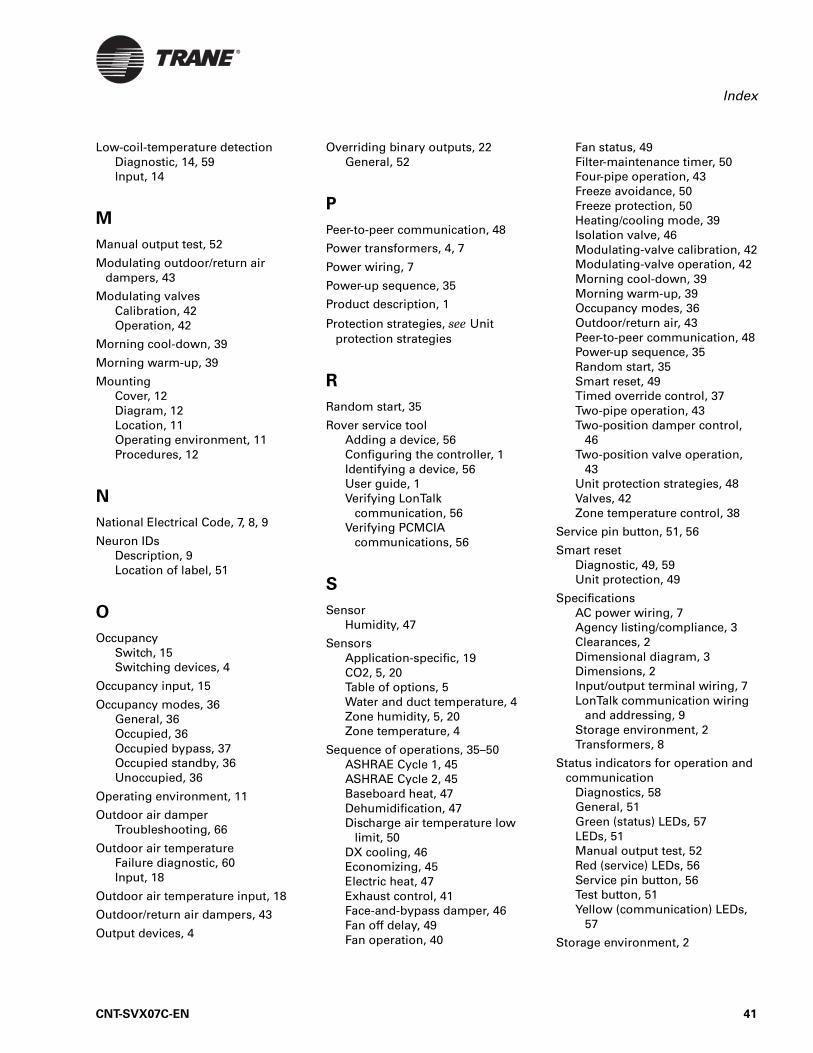
Index
Low-coil-temperature detectionDiagnostic, 14, 59Input, 14
M
Manual output test, 52
Modulating outdoor/return air dampers, 43
Modulating valvesCalibration, 42Operation, 42
Morning cool-down, 39
Morning warm-up, 39
MountingCover, 12Diagram, 12Location, 11Operating environment, 11Procedures, 12
N
National Electrical Code, 7, 8, 9
Neuron IDsDescription, 9Location of label, 51
O
OccupancySwitch, 15Switching devices, 4
Occupancy input, 15
Occupancy modes, 36General, 36Occupied, 36Occupied bypass, 37Occupied standby, 36Unoccupied, 36
Operating environment, 11
Outdoor air damperTroubleshooting, 66
Outdoor air temperatureFailure diagnostic, 60Input, 18
Outdoor air temperature input, 18
Outdoor/return air dampers, 43
Output devices, 4
Overriding binary outputs, 22General, 52
P
Peer-to-peer communication, 48
Power transformers, 4, 7
Power wiring, 7
Power-up sequence, 35
Product description, 1
Protection strategies, see Unit protection strategies
R
Random start, 35
Rover service toolAdding a device, 56Configuring the controller, 1Identifying a device, 56User guide, 1Verifying LonTalk
communication, 56Verifying PCMCIA
communications, 56
S
SensorHumidity, 47
SensorsApplication-specific, 19CO2, 5, 20Table of options, 5Water and duct temperature, 4Zone humidity, 5, 20Zone temperature, 4
Sequence of operations, 35–50ASHRAE Cycle 1, 45ASHRAE Cycle 2, 45Baseboard heat, 47Dehumidification, 47Discharge air temperature low
limit, 50DX cooling, 46Economizing, 45Electric heat, 47Exhaust control, 41Face-and-bypass damper, 46Fan off delay, 49Fan operation, 40
Fan status, 49Filter-maintenance timer, 50Four-pipe operation, 43Freeze avoidance, 50Freeze protection, 50Heating/cooling mode, 39Isolation valve, 46Modulating-valve calibration, 42Modulating-valve operation, 42Morning cool-down, 39Morning warm-up, 39Occupancy modes, 36Outdoor/return air, 43Peer-to-peer communication, 48Power-up sequence, 35Random start, 35Smart reset, 49Timed override control, 37Two-pipe operation, 43Two-position damper control,
46Two-position valve operation,
43Unit protection strategies, 48Valves, 42Zone temperature control, 38
Service pin button, 51, 56
Smart resetDiagnostic, 49, 59Unit protection, 49
SpecificationsAC power wiring, 7Agency listing/compliance, 3Clearances, 2Dimensional diagram, 3Dimensions, 2Input/output terminal wiring, 7LonTalk communication wiring
and addressing, 9Storage environment, 2Transformers, 8
Status indicators for operation and communication
Diagnostics, 58General, 51Green (status) LEDs, 57LEDs, 51Manual output test, 52Red (service) LEDs, 56Service pin button, 56Test button, 51Yellow (communication) LEDs,
57
Storage environment, 2
CNT-SVX07C-EN 41

Index
Switching devicesCondensate overflow, 4, 14Current sensing, 4Fan status, 4Freeze protection, 4, 14Low-coil-temperature, 4Occupancy, 4, 15
T
Temperature sensorsTable of options, 5Water and duct, 4Zone, 4
Termination resistors, 9
Test button, 51–52
Timeclock, 15
Timed override control, 37
Transformers, 4, 7, 8
TroubleshootingDX cooling, 65Electric heat failure, 65Fans, 63Outdoor air damper, 66Valves, 64
Two-pipe operation, 43
Two-position damper control, 46
Two-position valve operation, 43
Types of diagnostics, 58
U
UL, see Agency listing/compliance
Unit protection strategiesCondensate overflow, 49Discharge air temperature low
limit, 50Fan off delay, 49Fan status, 49Filter-maintenance timer, 50Freeze avoidance, 50Freeze protection, 50Low-coil-temperature
protection, 49Smart reset, 49
Unit ventilators, 1, 21
Universal 4–20 mA, 19
V
ValvesActuators, 4Calibration of modulating, 42Four-pipe operation, 43General operation, 42Isolation-valve operation, 43Operation of modulating, 42Operation of two-position, 43Supported applications, 1, 21,
42Tri-state modulating, 1, 21, 42Troubleshooting, 64Two-pipe operation, 43Two-position, 1, 21
W
Water and duct temperature sensors, 4
WiringBAS communication, 9Compliance with National
Electrical Code, 7, 8, 9General, 7–9Input/output terminals, 7LonTalk communication, 9Minimum requirements, 22Requirements and options,
22–34
Wiring diagrams, 22–34Electric heat unit, 30Electric heat unit with DX
cooling, 29Four-pipe heating/cooling unit
with auto changeover, 27Four-pipe heating/cooling unit
with face-and-bypass damper, 33
Four-pipe hydronic heating/cooling unit, 26
Two-pipe heating unit with DX cooling, 28
Two-pipe heating/cooling unit with face-and-bypass damper, 32
Two-pipe hydronic heating/cooling unit with auto changeover, 25
Two-pipe hydronic-cooling unit, 23
Two-pipe hydronic-heating unit, 24
Z
Zone humiditySensor, 5
Zone temperatureInput, 16Sensors, 4
Zone temperature control, 38
Zone temperature failure diagnostic, 59
42 CNT-SVX07C-EN


Trane A business of American Standard Companieswww.trane.com
For more information contact your local Traneoffice or e-mail us at [email protected]
Trane has a policy of continuous product and produchange design and specifications without notice. Otion and servicing of equipment referred to in this p
Literature Order Number CNT-SVX07C-EN
File Number SV-ES-BAS-CNT-SVX-0
Supersedes CNT-SVX07B-EN Octob
Stocking Location Inland
ct data improvement and reserves the right to nly qualified technicians should perform the installa-ublication.
7C-EN 0405
er 2001