
Installation and Operation Tracer Zone Controller · Installation and Operation Tracer™ ZN511...
87
CNT-SVX06B-EN Installation and Operation Tracer ™ ZN511 Zone Controller
Transcript of Installation and Operation Tracer Zone Controller · Installation and Operation Tracer™ ZN511...

CNT-SVX06B-EN
Installation and Operation
Tracer™ ZN511Zone Controller

Installation and Operation
Tracer™ ZN511 Zone Controller
CNT-SVX06B-EN
April 2005

CNT-SVX06B-EN

Tracer ZN511 Zone Controller Installation and Operation
This guide and the information in it are the property of American Standard Inc. and may not be used or reproduced in whole or in part, without the written permission of American Standard Inc. Trane, a business of American Standard, Inc., has a policy of continuous product and product data improvement and reserves the right to change design and specification without notice.
Although Trane has tested the hardware and software described in this guide, no guarantee is offered that the hardware and software are error free.
Trane reserves the right to revise this publication at any time and to make changes to its content without obligation to notify any per-son of such revision or change.
Trane may have patents or patent applications covering items in this publication. By providing this document, Trane does not imply giving license to these patents.
The following are trademarks or registered trademarks of American Standard Inc.: Trane, Tracer, Rover.
The following are trademarks or registered trademarks of their respective companies or organizations: BACnet from ASHRAE; Neuron, LonMark, LonTalk, and LonWorks from Echelon Corporation; National Electrical Code form the National Fire Proctection Association, Inc.
Printed in the U.S.A.
© 2005 American Standard Inc. All rights reserved.
™ ®
™ ®
CNT-SVX06B-EN

CNT-SVX06B-EN

NOTICE:Warnings and Cautions appear at appropriate sections throughout this manual. Read these carefully:
WARNINGIndicates a potentially hazardous situation, which, if not avoided, could result in death or serious injury.
CAUTIONIndicates a potentially hazardous situation, which, if not avoided, may result in minor or moderate injury.
It may also be used to alert against unsafe practices.
CAUTIONIndicates a situation that may result in equipment damage or property damage.
The following format and symbol conventions appear at appropriate sections throughout this manual:
IMPORTANTAlerts installer, servicer, or operator to potential actions that could cause the product or system to
operate improperly but will not likely result in potential for damage.
This symbol precedes a procedure that consists of only a single step.
Note:
A note may be used to make the reader aware of useful information, to clarify a point, or to describe options or alternatives.
CNT-SVX06B-EN

CNT-SVX06B-EN

Contents
Chapter 1 Overview and specifications . . . . . . . . . . . . . . . . . . 1
Product description . . . . . . . . . . . . . . . . . . . . . . . . . . . . . . . . . . . . . . . . . . 1
Storage environment . . . . . . . . . . . . . . . . . . . . . . . . . . . . . . . . . . . . . . . . . 1
Agency listing/compliance. . . . . . . . . . . . . . . . . . . . . . . . . . . . . . . . . . . . . 2
Dimensions . . . . . . . . . . . . . . . . . . . . . . . . . . . . . . . . . . . . . . . . . . . . . . . . . 2
Clearances . . . . . . . . . . . . . . . . . . . . . . . . . . . . . . . . . . . . . . . . . . . . . . . . . . 2
Additional components . . . . . . . . . . . . . . . . . . . . . . . . . . . . . . . . . . . . . . . 4
Power transformer . . . . . . . . . . . . . . . . . . . . . . . . . . . . . . . . . . . . . . . . 4
Zone temperature sensors . . . . . . . . . . . . . . . . . . . . . . . . . . . . . . . . . 4
Water and duct temperature sensors . . . . . . . . . . . . . . . . . . . . . . . . . 4
Binary input switching devices . . . . . . . . . . . . . . . . . . . . . . . . . . . . . 4
Output relays . . . . . . . . . . . . . . . . . . . . . . . . . . . . . . . . . . . . . . . . . . . . 5
Valve and damper actuators . . . . . . . . . . . . . . . . . . . . . . . . . . . . . . . . 5
Chapter 2 General wiring information . . . . . . . . . . . . . . . . . . . 7
Input/output terminal wiring . . . . . . . . . . . . . . . . . . . . . . . . . . . . . . . . . . . 7
AC power wiring . . . . . . . . . . . . . . . . . . . . . . . . . . . . . . . . . . . . . . . . . . . . . 8
Communication-link wiring and addressing . . . . . . . . . . . . . . . . . . . . . . 9
Chapter 3 Mounting the controller . . . . . . . . . . . . . . . . . . . . 11
Location recommendations . . . . . . . . . . . . . . . . . . . . . . . . . . . . . . . . . . . .11
Operating environment requirements . . . . . . . . . . . . . . . . . . . . . . . . . . .11
Mounting recommendations . . . . . . . . . . . . . . . . . . . . . . . . . . . . . . . . . . 12
Chapter 4 Applications for the heat pump configuration . . 13
Binary inputs for water-source heat pump applications . . . . . . . . . . . . 14
BI1: Low-temperature detection (circuit 2) . . . . . . . . . . . . . . . . . . . . 14
BI2: Condensate overflow . . . . . . . . . . . . . . . . . . . . . . . . . . . . . . . . . 15
BI3: Occupancy or generic binary input . . . . . . . . . . . . . . . . . . . . . . 15
BI4 and BI5: High/low pressure cutout . . . . . . . . . . . . . . . . . . . . . . 16
Compressor contactor monitoring. . . . . . . . . . . . . . . . . . . . . . . 16
Compressor line-voltage monitoring. . . . . . . . . . . . . . . . . . . . . 18
High/low pressure switch monitoring . . . . . . . . . . . . . . . . . . . . 18
Analog inputs for water-source heat pump applications . . . . . . . . . . . 19
CNT-SVX06B-EN i
Contents
ZN: Zone temperature . . . . . . . . . . . . . . . . . . . . . . . . . . . . . . . . . . . . 19
SET: Local set point. . . . . . . . . . . . . . . . . . . . . . . . . . . . . . . . . . . . . . . 20
FAN: Fan mode input . . . . . . . . . . . . . . . . . . . . . . . . . . . . . . . . . . . . . 20
AI1: Leaving water temperature . . . . . . . . . . . . . . . . . . . . . . . . . . . 20
AI2: Discharge air temperature . . . . . . . . . . . . . . . . . . . . . . . . . . . . . 21
Binary outputs for water-source heat pump applications . . . . . . . . . . . 21
Generic binary output. . . . . . . . . . . . . . . . . . . . . . . . . . . . . . . . . . . . . 22
Overriding binary outputs . . . . . . . . . . . . . . . . . . . . . . . . . . . . . . . . . 22
Wiring requirements and options . . . . . . . . . . . . . . . . . . . . . . . . . . . . . . 22
Chapter 5 Sequence of operations for the heat pump
configuration . . . . . . . . . . . . . . . . . . . . . . . . . . . . 25
Power-up sequence . . . . . . . . . . . . . . . . . . . . . . . . . . . . . . . . . . . . . . . . . . 25
Random start . . . . . . . . . . . . . . . . . . . . . . . . . . . . . . . . . . . . . . . . . . . . . . . 26
Zone temperature control. . . . . . . . . . . . . . . . . . . . . . . . . . . . . . . . . . . . . 26
Occupancy modes. . . . . . . . . . . . . . . . . . . . . . . . . . . . . . . . . . . . . . . . . . . 26
Occupied mode. . . . . . . . . . . . . . . . . . . . . . . . . . . . . . . . . . . . . . . . . . 26
Unoccupied mode. . . . . . . . . . . . . . . . . . . . . . . . . . . . . . . . . . . . . . . . 27
Occupied standby mode . . . . . . . . . . . . . . . . . . . . . . . . . . . . . . . . . . 27
Occupied bypass mode . . . . . . . . . . . . . . . . . . . . . . . . . . . . . . . . . . . 27
Timed override control . . . . . . . . . . . . . . . . . . . . . . . . . . . . . . . . . . . . . . . 28
Morning warm-up . . . . . . . . . . . . . . . . . . . . . . . . . . . . . . . . . . . . . . . . . . . 28
Morning cool-down. . . . . . . . . . . . . . . . . . . . . . . . . . . . . . . . . . . . . . . . . . 28
Heating or cooling mode . . . . . . . . . . . . . . . . . . . . . . . . . . . . . . . . . . . . . 29
Fan operation and status . . . . . . . . . . . . . . . . . . . . . . . . . . . . . . . . . . . . . 29
Compressor operation . . . . . . . . . . . . . . . . . . . . . . . . . . . . . . . . . . . . . . . 29
Outdoor air damper operation . . . . . . . . . . . . . . . . . . . . . . . . . . . . . . . . . 30
Reversing valve operation . . . . . . . . . . . . . . . . . . . . . . . . . . . . . . . . . . . . 30
Peer-to-peer (master/slave) data sharing . . . . . . . . . . . . . . . . . . . . . . . . 30
Unit protection strategies . . . . . . . . . . . . . . . . . . . . . . . . . . . . . . . . . . . . . 31
Smart reset . . . . . . . . . . . . . . . . . . . . . . . . . . . . . . . . . . . . . . . . . . . . . 31
Low-temperature protection . . . . . . . . . . . . . . . . . . . . . . . . . . . . . . . 31
Condensate overflow . . . . . . . . . . . . . . . . . . . . . . . . . . . . . . . . . . . . . 31
High/low pressure cutout . . . . . . . . . . . . . . . . . . . . . . . . . . . . . . . . . . 31
Filter-maintenance timer . . . . . . . . . . . . . . . . . . . . . . . . . . . . . . . . . . 31
Fan off delay . . . . . . . . . . . . . . . . . . . . . . . . . . . . . . . . . . . . . . . . . . . . 32
ii CNT-SVX06B-EN

Contents
Chapter 6 Applications for the 1 heat/1 cool
configuration. . . . . . . . . . . . . . . . . . . . . . . . . . . . . 33
Binary inputs for 1 heat/1 cool applications . . . . . . . . . . . . . . . . . . . . . . 34
BI1: Low-temperature detection . . . . . . . . . . . . . . . . . . . . . . . . . . . . 34
BI2: Condensate overflow . . . . . . . . . . . . . . . . . . . . . . . . . . . . . . . . . 34
BI3: Occupancy or generic binary input . . . . . . . . . . . . . . . . . . . . . . 35
Analog inputs for 1 heat/1 cool applications . . . . . . . . . . . . . . . . . . . . . 35
ZN: Zone temperature . . . . . . . . . . . . . . . . . . . . . . . . . . . . . . . . . . . . 36
SET: Local set point . . . . . . . . . . . . . . . . . . . . . . . . . . . . . . . . . . . . . . 36
FAN: Fan mode input . . . . . . . . . . . . . . . . . . . . . . . . . . . . . . . . . . . . . 36
AI1: Entering water temperature sampling . . . . . . . . . . . . . . . . . . . 37
AI2: Discharge air temperature . . . . . . . . . . . . . . . . . . . . . . . . . . . . . 37
Binary outputs for 1 heat/1 cool applications. . . . . . . . . . . . . . . . . . . . . 38
Generic binary output . . . . . . . . . . . . . . . . . . . . . . . . . . . . . . . . . . . . 38
Overriding binary outputs . . . . . . . . . . . . . . . . . . . . . . . . . . . . . . . . . 38
Wiring requirements and options . . . . . . . . . . . . . . . . . . . . . . . . . . . . . . 39
Chapter 7 Sequence of operations for the 1 heat/1 cool
configuration. . . . . . . . . . . . . . . . . . . . . . . . . . . . . 47
Power-up sequence . . . . . . . . . . . . . . . . . . . . . . . . . . . . . . . . . . . . . . . . . 47
Random start. . . . . . . . . . . . . . . . . . . . . . . . . . . . . . . . . . . . . . . . . . . . . . . 48
Zone temperature control . . . . . . . . . . . . . . . . . . . . . . . . . . . . . . . . . . . . 48
Occupancy modes . . . . . . . . . . . . . . . . . . . . . . . . . . . . . . . . . . . . . . . . . . 48
Occupied mode . . . . . . . . . . . . . . . . . . . . . . . . . . . . . . . . . . . . . . . . . 48
Unoccupied mode . . . . . . . . . . . . . . . . . . . . . . . . . . . . . . . . . . . . . . . 49
Occupied standby mode . . . . . . . . . . . . . . . . . . . . . . . . . . . . . . . . . . 49
Occupied bypass mode . . . . . . . . . . . . . . . . . . . . . . . . . . . . . . . . . . . 49
Timed override control. . . . . . . . . . . . . . . . . . . . . . . . . . . . . . . . . . . . . . . 50
Morning warm-up. . . . . . . . . . . . . . . . . . . . . . . . . . . . . . . . . . . . . . . . . . . 50
Morning cool-down . . . . . . . . . . . . . . . . . . . . . . . . . . . . . . . . . . . . . . . . . 50
Heating or cooling mode . . . . . . . . . . . . . . . . . . . . . . . . . . . . . . . . . . . . . 51
Entering water temperature sampling function. . . . . . . . . . . . . . . . . . . 51
Fan operation and status . . . . . . . . . . . . . . . . . . . . . . . . . . . . . . . . . . . . . 52
Two-position valve operation . . . . . . . . . . . . . . . . . . . . . . . . . . . . . . . . . 53
Two-pipe operation . . . . . . . . . . . . . . . . . . . . . . . . . . . . . . . . . . . . . . 53
Four-pipe operation . . . . . . . . . . . . . . . . . . . . . . . . . . . . . . . . . . . . . . 53
Electric heat operation . . . . . . . . . . . . . . . . . . . . . . . . . . . . . . . . . . . . 54
Outdoor air damper operation . . . . . . . . . . . . . . . . . . . . . . . . . . . . . . . . 54
Peer-to-peer (master/slave) data sharing . . . . . . . . . . . . . . . . . . . . . . . . 54
CNT-SVX06B-EN iii
Contents
Unit protection strategies . . . . . . . . . . . . . . . . . . . . . . . . . . . . . . . . . . . . . 55
Smart reset . . . . . . . . . . . . . . . . . . . . . . . . . . . . . . . . . . . . . . . . . . . . . 55
Low-temperature protection . . . . . . . . . . . . . . . . . . . . . . . . . . . . . . . 55
Condensate overflow . . . . . . . . . . . . . . . . . . . . . . . . . . . . . . . . . . . . . 55
Filter-maintenance timer . . . . . . . . . . . . . . . . . . . . . . . . . . . . . . . . . . 55
Fan off delay . . . . . . . . . . . . . . . . . . . . . . . . . . . . . . . . . . . . . . . . . . . . 55
Chapter 8 Status indicators for operation and
communication . . . . . . . . . . . . . . . . . . . . . . . . . . 57
Test button . . . . . . . . . . . . . . . . . . . . . . . . . . . . . . . . . . . . . . . . . . . . . . . . . 57
Manual output test . . . . . . . . . . . . . . . . . . . . . . . . . . . . . . . . . . . . . . . . . . 58
Service button (pin). . . . . . . . . . . . . . . . . . . . . . . . . . . . . . . . . . . . . . . . . . 58
Interpreting LEDs. . . . . . . . . . . . . . . . . . . . . . . . . . . . . . . . . . . . . . . . . . . . 60
Diagnostics . . . . . . . . . . . . . . . . . . . . . . . . . . . . . . . . . . . . . . . . . . . . . . . . 62
Clearing diagnostics . . . . . . . . . . . . . . . . . . . . . . . . . . . . . . . . . . . . . . 66
Manual (latching) diagnostics . . . . . . . . . . . . . . . . . . . . . . . . . . . 66
Automatic (nonlatching) diagnostics . . . . . . . . . . . . . . . . . . . . . 66
Smart reset diagnostics . . . . . . . . . . . . . . . . . . . . . . . . . . . . . . . . 66
Informational diagnostics . . . . . . . . . . . . . . . . . . . . . . . . . . . . . . 66
Chapter 9 Troubleshooting . . . . . . . . . . . . . . . . . . . . . . . . . . . 67
Index . . . . . . . . . . . . . . . . . . . . . . . . . . . . . . . . . . . . 71
iv CNT-SVX06B-EN

Chapter 1
Overview and specifications
This guide provides installation and configuration information for the Tracer ZN511 zone controller, as well as a description of its operations. The overview includes a product description, specifications, and descrip-tions of ancillary products that may be necessary.
Product descriptionThe Tracer ZN511 is an application-specific controller that provides direct-digital zone temperature control. The controller can operate as a stand-alone device or as part of a building automation system (BAS). Communication between the controller and a BAS occurs via a LonTalk communication link, which is based on the LonTalk protocol.
The controller is designed to be field-installed and is sent from the factory unconfigured. You can configure the controller, using the PC-based Rover service tool, to support either of the following configurations:
• Water-source heat pumps, one or two compressors• 1 heat/1 cool fan coils with two-position valves
Storage environmentIf a Tracer ZN511 zone controller is to be stored for a substantial amount of time, store it in an indoor environment that meets the following requirements:
• Temperature: –40° to 185°F (–40° to 85°C)• Relative humidity: 5–95%, noncondensing
Note:
For information about using the Rover service tool, see the Rover Installation/Operation/Programming guide (EMTX-SVX01A-EN).
CNT-SVX06B-EN 1

Chapter 1 Overview and specifications
Agency listing/complianceCE—Immunity: EN 50082-1:1997; EN 50082-2:1995
CE—Emissions: EN 50081-1:1992 (CISPR 22) Class B
UL and C-UL 916 listed: Energy management system
UL 94-5V (UL flammability rating for plenum use)
FCC Part 15, Class A
DimensionsPlastic-cover model dimensions
For complete dimensional drawing, see Figure 1 on page 3.
• Height: 5.375 in. (137 mm)• Width: 6.875 in. (175 mm)• Depth: 2 in. (51 mm)
Metal-cover model dimensions
For complete dimensional drawing, see Figure 2 on page 3.
• Height: 9.0 in (25 mm)• Width: 10.37in. (263 mm)• Depth: 2.25 in. (58 mm)
ClearancesFor wiring, ventilation, and maintenance, provide the following minimum clearances for the controller:
Plastic-cover model
• Front: 4.0 in. (102 mm)• Each side: 1.0 in. (25 mm)• Top and bottom: 4.0 in. (102 mm)
Metal-cover model
• Front: 24.0 in. (610 mm)• Each side: 2.0 in. (51 mm)• Top and bottom: 1.0 in. (25 mm)
2 CNT-SVX06B-EN

Clearances
Figure 1. ZN511 plastic-cover model dimensions and clearances
Figure 2. ZN511 Metal-cover model dimensions and clearances
1 in. (25 mm)
4 in. (102 mm)
5.625 in. (143 mm)
5.375 in. (137 mm)
1 in. (25 mm)
Clearances
Dimensions
6.31 in. (160 mm)
4 in. (102 mm)
4 in. (102 mm) 6.875 in.
(175 mm)
2 in. (51 mm)
1 in. (25 mm)
9 in. (229 mm)
2 in.(51 mm)
24 in.(610 mm)
10.37 in.(263 mm)
width with cover
1 in. (25 mm)
2.25 in. (58 mm)
2 in. (51 mm)
7 in. (178 mm)
1 in.(25 mm)
1.875 in. (48 mm) 6.5 in.
(165 mm)
10.25 in. (260 mm)
width without cover
0.28 in. (7 mm)
9 in. (229 mm)
Clearances
Dimensions
CNT-SVX06B-EN 3

Chapter 1 Overview and specifications
Additional componentsThe Tracer ZN511 zone controller may require the use of additional com-ponents for monitoring and proper control of the associated fan coil or heat pump. Using these components depends on the application. They are not included with the Tracer ZN511 zone controller.
Power transformer
A transformer providing 24 Vac is required to power the Tracer ZN511 zone controller and associated output relays and valve and damper actua-tors.
Zone temperature sensors
Table 1 shows the Trane zone temperature sensors that are supported by the Tracer ZN511 zone controller.
Water and duct temperature sensors
Temperature sensors must be Trane 10 kΩ (at 25°C) thermistors. Enter-ing water (fan coil), leaving water (heat pump), and discharge air inputs may use a sealed temperature sensor (part number 4190 1100).
Binary input switching devices
Occupancy, condensate overflow, and low-temperature inputs accept switching devices that may have normally open or normally closed dry contacts.
Table 1. Tracer zone temperature sensor options
BAS order number
Use
Fan ZoneTimed
override buttons
Comm jack
High Med Low Auto Off
Set-point
thumb-wheel
Tempe-ature
sensorOn
Can-cel
4190 1087 Any x
4190 1088 Any x x x x
4190 1090 Heat pump x x x x x
4190 1094 Heat pump x x x
4190 1095 Unit vent x x x x x x x x
4190 1115 Fan coil x x x x x x x x x x
4190 1116 Unit vent x x x x x x x x x
4190 1117 Any x x x x x x x
4 CNT-SVX06B-EN

Additional components
Current-sensing switches must be capable of switching 24 Vac for heat-pump-compressor circuit applications (see “Compressor line-voltage mon-itoring” on page 18). The current-sensing switch must sense line voltage current as low as 2 A. This amperage is common for a 1/2 ton compressor, which is typically the smallest compressor on a heat pump.
Output relays
Relays for fan (speed) control connected to the Tracer ZN511 binary out-puts cannot exceed 12 VA (0.5 A) current draw at 24 Vac.
Valve and damper actuators
Actuators cannot exceed 12 VA draw at 24 Vac. Use actuators with on/off action and spring return to normally open or closed position based on the desired default position.
CNT-SVX06B-EN 5

Chapter 1 Overview and specifications
6 CNT-SVX06B-EN

Chapter 2
General wiring information
This chapter provides specifications and general information about wir-ing the Tracer ZN511 zone controller. The controller requires wiring for:
• Input/output terminals• AC power to the controller• Communication-link wiring, if the controller is to communicate with a
building automation system (BAS)
Input/output terminal wiringAll input/output terminal wiring for the Tracer ZN511 zone controller is application specific and dependant on the configuration of the controller. Input/output terminal wiring must meet the following requirements:
• All wiring must comply with the National Electrical Code and local codes.
• Use only 18 AWG, twisted-pair wire with stranded, tinned-copper conductors. (Shielded wire is recommended.)
• Binary input and output wiring must not exceed 1000 ft (100 m).• Analog input wiring must not exceed 300 ft (100 m).• Do not run input/output wires in the same wire bundle with any ac
power wires.
For application-specific wiring information and diagrams, see Chapter 4, “Applications for the heat pump configuration”, and Chapter 6, “Applica-tions for the 1 heat/1 cool configuration”.
CNT-SVX06B-EN 7

Chapter 2 General wiring information
AC power wiring
CAUTIONComplete input/output wiring before applying power to the Tracer
ZN511 zone controller. Failure to do so may cause damage to the con-
troller or power transformer due to inadvertent connections to power
circuits.
CAUTIONMake sure that the 24 Vac transformer is properly grounded. Failure to
do so may result in damage to equipment and/or personal injury.
IMPORTANTDo not share 24 Vac between controllers.
All wiring must comply with National Electrical Code and local codes.
The ac power connections are in the top left corner of the Tracer ZN511 zone controller (see Figure 3).
Figure 3. Connecting ac power wires to the controller
If you are providing a new transformer for power, use a UL-listed Class 2 power transformer supplying a nominal 24 Vac (19–30 Vac). The trans-former must be sized to provide adequate power to the Tracer ZN511 zone controller (9 VA) and output devices, including relays and valve actuators, to a maximum of 12 VA per output utilized. The Tracer ZN511 may be powered by an existing transformer integral to the controlled heat pump or fan coil, provided the transformer has adequate power available and adequate grounding is observed.
24 Vac unit transformer
H
N
8 CNT-SVX06B-EN

Communication-link wiring and addressing
Communication-link wiring and
addressingThe Tracer ZN511 zone controller communicates with the BAS and with other LonTalk controllers via a LonTalk communication link. For impor-tant instructions on network wiring, refer to the Tracer Summit Hard-ware and Software Installation guide (BMTX-SVN01A-EN). Wiring for the communication link must meet the following requirements:
• All wiring must comply with the National Electrical Code and local codes.
• 22 AWG Level 4 unshielded communications wire recommended for most Comm5 installations.
• Termination resistors are required for wiring LonTalk devices com-municating on a network. For important instructions on using termi-nation resistors for LonTalk applications, refer to the Tracer Summit Hardware and Software Installation guide (BMTX SVN01A-EN).
Each Tracer ZN511 zone controller has a unique 12-character alphanu-meric device address for communicating on a BAS network. This address, referred to as a Neuron ID, is assigned in the factory before the product is shipped. Each controller can be identified by viewing its unique Neuron ID, which is on a printed label attached to the circuit board of the control-ler. Additional adhesive-backed, peel-off Neuron ID labels are tethered to the controller for placing on mechanical prints or unit location work-sheets. The Neuron ID will appear when communication is established with the Rover service tool or a BAS. An example Neuron ID is 00-01-64-1C-2B-00.
CNT-SVX06B-EN 9

Chapter 2 General wiring information
10 CNT-SVX06B-EN

Chapter 3
Mounting the controller
This chapter gives recommendations and requirements for mounting the Tracer ZN511 zone controller.
Location recommendationsFor fan coil applications, the controller can usually be mounted inside the end pocket of the unit. For heat pump applications, the controller should be mounted on the side of the unit. Trane recommends locating the Tracer ZN511 zone controller:
• Near the controlled piece of equipment to reduce wiring costs• Where it is easily accessible for service personnel• Where public access is restricted to minimize the possibility of tam-
pering or vandalism
Operating environment requirementsOperate a Tracer ZN511 zone controller in an indoor environment that meets the following requirements:
• Temperature: 32°F to 140°F (0°C to 60°C)• Relative humidity: 5–95%, noncondensing
CNT-SVX06B-EN 11

Chapter 3 Mounting the controller
Mounting recommendationsMounting recommendations are as follows:
IMPORTANTMount the Tracer ZN511 zone controller with the cover on to avoid the
possibility of damaging the circuit board during installation.
• Mount the controller in any direction, other than with the front of the cover facing downward.
• Mount using the two 3/16 in. (0.19 mm) radius mounting holes pro-vided (see Figure 4). Mounting fasteners are not included.
• Attach the controller securely so it can withstand vibrations of associ-ated HVAC equipment.
• When the controller is mounted in a small enclosed compartment, complete all wiring connections before securing the controller in the compartment.
Figure 4. Mounting the Tracer ZN511 zone controller
12 CNT-SVX06B-EN

Chapter 4
Applications for the heat
pump configuration
This chapter provides information about the function of inputs and out-puts and examples of wiring for typical heat pump applications. The types of heat pump applications supported by the Tracer ZN511 zone controller are shown in Table 2.
The decision to wire many of the input/output terminals discussed in this chapter depends on the application. Figure 7 on page 23 shows the mini-mum wiring necessary for proper operation of all heat pump applications. Table 8 on page 24 includes all required and all optional components that can be wired for heat pump applications.
IMPORTANTThe Tracer ZN511 zone controller ships from the factory in an unconfig-
ured state. Use the PC-based Rover service tool to configure the con-
troller. If the controller is part of a BAS, it is recommended that you
configure the controller after BAS communication has been estab-
lished.
Table 2. Heat pump applications for the Tracer ZN511 zone controller
ApplicationSingle
compressorDual
compressor
Water-source heat pump (heating/cooling) × ×
Water-source heat pump (cooling only) × ×
CNT-SVX06B-EN 13

Chapter 4 Applications for the heat pump configuration
Binary inputs for water-source heat
pump applicationsThe Tracer ZN511 zone controller includes five binary inputs. Each binary input associates an input signal of 0 Vac with open contacts and 24 Vac with closed contacts. Table 3 gives the function of each binary input for water-source heat pump applications. Each function is explained in the succeeding paragraphs. For an explanation of the diagnostics gen-erated by each binary input, see “Diagnostics” on page 62. For more infor-mation about how the controller operates, see Chapter 5, “Sequence of operations for the heat pump configuration”.
BI1: Low-temperature detection (circuit 2)
The function of low-temperature detection is to protect a heat exchanger from freezing. BI1 is used to protect the second heat exchanger in a two-compressor unit. If BI1 is wired to a binary low-temperature detection device (freeze-protection switch), the ZN511 will detect a low-tempera-ture condition and generate a Low Temp Detection Circuit 2 diagnostic.
Low-temperature detection for the first heat exchanger is always done by AI1 (see “AI1: Leaving water temperature” on page 20).
Table 3. Binary inputs for water-source heat pump applications
Binary input terminal label
Function
BI1 Low-temperature detection
BI2 Condensate overflow
BI3 Occupancy or generic binary input
BI4 and V4 High and low pressure cutout (compressor 1)
BI5 and V5 High and low pressure cutout (compressor 2)
Note:
Some heat pumps have a safety circuit to protect the unit. This circuit contains the compressor contactor, a lockout relay, and unit safeties (Figure 5 on page 17). These safeties may include a freeze-protection switch. For the Tracer ZN511 to generate a Low Temp Detection Circuit 2 diagnostic, the freeze-protection switch must be removed from the safety circuit and wired directly to BI1. If the application does not warrant the use of BI1, configure the input as Not Used. Diagnostics for this func-tion will not be generated; however, units with a safety circuit containing a freeze-protection switch will maintain their exist-ing level of freeze protection.
14 CNT-SVX06B-EN

Binary inputs for water-source heat pump applications
BI2: Condensate overflow
The function of condensate overflow is to prevent the condensate drain pan from overflowing and causing water damage to the building. If BI2 is wired to a condensate overflow switch and the level of condensate reaches the trip point, the Tracer ZN511 will detect the condition and generate a Condensate Overflow diagnostic.
BI3: Occupancy or generic binary input
The function of occupancy is to save energy on unit operation by changing room set points when the zone is unoccupied. BI3 is used for two occu-pancy-related functions. For stand-alone controllers, this binary input can be wired to a binary switch (occupancy sensor) or time clock to determine the occupancy mode—either occupied or unoccupied. For controllers receiving a BAS-communicated occupancy request, the function of BI3 is to change the mode from occupied to occupied standby. (For more informa-tion on occupancy-related functions, see “Occupancy modes” on page 26.)
BI3 is the only input that can be configured as a generic binary input. When configured as a generic binary input, it can be monitored only by a BAS, and has no direct effect on Tracer ZN511 operation.
Note:
On some heat pumps, the condensate overflow switch may be a safety wired in the safety circuit (see Figure 5 on page 17). For the Tracer ZN511 to generate a Condensate Overflow diagnos-tic, the condensate overflow switch must be removed from the safety circuit and wired directly to BI2. If the application does not warrant the use of BI2, configure the input as Not Used. Diagnostics for this function will not be generated; however, units with a safety circuit containing a condensate overflow switch will maintain their existing level of condensate overflow protection.
CNT-SVX06B-EN 15
Chapter 4 Applications for the heat pump configuration
BI4 and BI5: High/low pressure cutout
The function of high- and low-pressure cutout is to protect the refrigerant circuit from abnormal pressure conditions by locking out (disabling) the compressor operation. Binary input 4 (terminals BI4 and V4) is used to lock out the first compressor and binary input 5 (terminals BI5 and V5) is used to lock out the second compressor. Upon an enable-compressor request, the controller waits 4 seconds before checking the status of BI4 or BI5. After that, the input must close (sense 24 Vac) to operate nor-mally. If the input opens for more than 200 ms, a High/Low Pressure Cut-out diagnostic will be generated for that compressor, and it will be locked out.
These inputs can be used in one of three ways:
• To monitor the compressor contactor• To monitor compressor line-voltage• To directly monitor the high and low pressure switches
Compressor contactor monitoring
By connecting BI4 to the first compressor contactor (see Figure 5 on page 17), the controller will monitor (indirectly) the high/low pressure safeties by monitoring the state of the compressor contactor. When the refrigerant circuit experiences an abnormal pressure condition, the high- or low-pressure cutout switch will trip the lockout relay, causing the com-pressor contactor to de-energize. This will result in the controller generat-ing a High/Low Pressure Cutout diagnostic. BI5 will perform the same function for the safety circuit of the second compressor.
Note:
BI4 and BI5 must have 24 Vac applied to them for the control-ler to allow heat pump operation. For this reason, an electrical jumper is factory installed between BI4 and V4, and between BI5 and V5. Terminals V4 and V5 supply 24 Vac for inputs BI4 and BI5, respectively. If either compressor contactor monitoring or line-voltage monitoring are used, the jumpers must be removed from the terminal strip. If neither is used, the jumpers must remain in the terminal strip for proper operation. If jump-ers are used, no High/Low Pressure Cutout diagnostics will be generated. However, units with a safety circuit containing high- and low-pressure switches will continue to protect against abnormal pressure conditions.
Note:
With the compressor contactor monitoring option, the controller will generate a High/Low Pressure Cutout diagnostic when any safeties, including the freeze-protection switch and the conden-sate overflow switch remaining in the safety circuit, trip the lockout relay.
16 CNT-SVX06B-EN

Binary inputs for water-source heat pump applications
To ensure that compressor contactor monitoring is functioning, perform the following test:
1. Using a voltmeter, place the probes across the 24-V side of the com-pressor contactor. When the compressor is in operation, the voltmeter should register a value close to 24 V.
2. Cause a fault to occur in the unit (example: manually close the water valve to lock the unit out on high pressure). The voltmeter should now register a value below 10 V.
If the voltmeter registers a value less than 10 V (most lockout relays will register a value less than 1 V), the controller will detect a lockout condi-tion and generate a High/Low Pressure Cutout diagnostic. If the voltme-ter registers a value greater than 10 V, the controller will not detect a lockout condition and will not generate a High/Low Pressure Cutout diag-nostic. In this case, the compressor line-voltage monitoring option, described in the next section, should be used.
Figure 5. Compressor contactor monitoring
Figure Note:
For units with two compressors, wire BI5 to compressor contactor 2 in the same way.
HPC LPC FreezestatCondensate overflow
Compressor contactor 1
Lockout relay
CNT-SVX06B-EN 17

Chapter 4 Applications for the heat pump configuration
Compressor line-voltage monitoring
By connecting BI4 and V4 to a field-supplied current-sensing relay, the controller will monitor the operation of the first compressor. Install the current-sensing relay onto the line-voltage wiring going to the compressor (see Figure 6). When the refrigerant circuit experiences an abnormal pressure condition, the high- or low-pressure cutout switch will trip the safety circuit, causing the compressor contactor to de-energize and the compressor operation to be locked out. This will result in the controller generating a High/Low Pressure Cutout diagnostic. This option may be required on heat pumps that use older lockout relays and in cases where the compressor contactor is inaccessible. BI5 and V5 will perform the same function for the second compressor.
Figure 6. Compressor line-voltage monitoring
Figure Note:
For units with two compressors, wire BI5 and V5 in the same way.
High/low pressure switch monitoring
By removing both the high- and low-pressure switches from the safety cir-cuit and wiring them, in series, directly to BI4 and V4, the controller will monitor the operation of the first compressor. When the refrigerant cir-cuit experiences an abnormal pressure condition, the high-and low-pres-sure cutout switches will open. This will result in the controller generating a high- or low-pressure cutout diagnostic and disabling com-
Note:
With the compressor line-voltage monitoring option, a control-ler will generate a High/Low Pressure Cutout diagnostic when any safeties, including the freeze-protection switch and the con-densate overflow switch, remaining in the safety circuit trip the lockout relay.
Current-sensing relay
Compressor 1Line voltage
Compressor contactor 1
18 CNT-SVX06B-EN

Analog inputs for water-source heat pump applications
pressor operation. BI5 and V5 will perform the same function for the sec-ond compressor.
Analog inputs for water-source heat
pump applicationsThe Tracer ZN511 zone controller includes five analog inputs. Table 4 gives the function of each input for water-source heat pump applications. Each function is described briefly in the succeeding paragraphs. For an explanation of the diagnostics generated by each analog input, see “Diag-nostics” on page 62. For more information about how the controller oper-ates, see Chapter 5, “Sequence of operations for the heat pump configuration”.
ZN: Zone temperature
The ZN analog input functions as the local (hardwired) zone temperature input. The controller receives the temperature as a resistance signal from a 10 kΩ thermistor in a standard Trane zone sensor wired to analog input ZN. A communicated zone temperature value can also be used for control-lers operating on a BAS. When both a hardwired and communicated zone temperature value is present, the controller uses the communicated value. When neither a hardwired nor communicated zone temperature value is present, the controller generates a Zone Temp Failure diagnostic.
The ZN analog input is also used to communicate timed override requests and cancel requests to the controller for applications utilizing a Trane zone sensor with the ON and CANCEL button option.
Table 4. Analog inputs for water-source heat pump application
Analog input terminal label
Function
ZN Zone temperature
SET Local set point
FAN Fan mode input
AI1 Leaving water temperature
AI2 Discharge air temperature
Note:
Use a GND terminal as the common ground for all zone sensor analog inputs. See Figure 8 on page 24.
CNT-SVX06B-EN 19

Chapter 4 Applications for the heat pump configuration
SET: Local set point
The SET analog input functions as the local (hardwired) temperature set-point input for applications utilizing a Trane zone sensor with a tempera-ture set-point thumbwheel. The ability to enable or disable the local set-point input is available in the Rover service tool. A communicated set-point value can also be used for controllers operating on a BAS. When both a hardwired and communicated set-point value is present, the con-troller uses the communicated value. When neither a hardwired nor a communicated set-point value is present, the controller uses the stored default set points (configurable in Rover). If a valid hardwired or commu-nicated set-point value is established and then is no longer present, the controller generates a Setpoint Failure diagnostic.
FAN: Fan mode input
The FAN analog input functions as the local (hardwired) fan mode switch input for applications utilizing the Trane zone sensor with a fan mode switch option. Valid fan modes for a heat pump are off and auto. The abil-ity to enable or disable the local fan mode input is available in the Rover service tool. A communicated fan mode request can also be used for con-trollers operating on a BAS. When both a hardwired and communicated fan mode value is present, the controller uses the communicated value. When neither a hardwired nor a communicated fan mode value is present, the controller recognizes the fan mode value as auto and oper-ates according to the default configuration. If a valid hardwired or com-municated fan mode value is established and then is no longer present, the controller generates a Fan Mode Failure diagnostic.
AI1: Leaving water temperature
The AI1 analog input functions as the local (hardwired) leaving water temperature input. The controller will not accept a BAS-communicated leaving water temperature value. The leaving water temperature is used to protect the heat exchanger from freezing. The controller compares the leaving water temperature to the Leaving Water Temperature Cutout Setpoint, which is configurable in Rover (default of 35°). When the leav-ing water temperature falls below the cutout set point, the controller gen-erates a Low Temp Detection Circuit 1 diagnostic. When a valid leaving water temperature is not present, the controller generates a Leaving Water Temp Failure diagnostic.
BI1 is used to protect the second heat exchanger from freezing in a two-compressor unit (see “BI1: Low-temperature detection (circuit 2)” on page 14).
Note:
Neither AI1 nor AI2 is polarity sensitive; you can connect either terminal to either sensor lead.
20 CNT-SVX06B-EN

Binary outputs for water-source heat pump applications
AI2: Discharge air temperature
The AI2 analog input functions as the local (hardwired) discharge air temperature input. The discharge air value is used for information and troubleshooting only and does not affect the operation of the controller. The controller receives the temperature as a resistance signal from a 10 kΩ (thermistor wired to AI2). A communicated discharge air tempera-ture value can also be used for controllers operating on a BAS. When both a hardwired and communicated discharge air temperature value is present, the controller uses the communicated value. If a valid hardwired or communicated discharge air temperature value is established and then is no longer present, the controller generates a Discharge Air Temp Fail-ure diagnostic.
Binary outputs for water-source heat
pump applicationsThe heat pump configuration supports applications with the following components:
• A single-speed supply fan• A reversing valve• One or two compressors• A two-position outdoor air ventilation damper (optional)
A Tracer ZN511 zone controller has six binary outputs. Each binary out-put is a relay with an output rating of 12 VA. Table 5 describes the func-tion of each output for water-source heat pump applications.
Note:
Neither AI1 nor AI2 is polarity sensitive; you can connect either terminal to either sensor lead.
Table 5. Binary outputs for water-source heat pump applications
Binary output terminal label
Function
1 Fan
2 Reversing valve
3 Not used
4 Compressor 1
5 Compressor 2
6 Two-position outdoor air damper or generic binary output
CNT-SVX06B-EN 21

Chapter 4 Applications for the heat pump configuration
Generic binary output
Binary output 6 is the only output that can be configured as a generic binary output. When configured as a generic binary output, it can be monitored only by a BAS, and has no direct effect on Tracer ZN511 opera-tion.
Overriding binary outputs
The Tracer ZN511 controller includes a manual output test. Use this fea-ture to manually control the outputs in a defined sequence. For more information about the manual output test, see “Manual output test” on page 58.
Wiring requirements and optionsTable 6 and Figure 7 on page 23 show required controller inputs for mini-mal proper operation of all heat pump applications.
Figure 8 on page 24 shows all required and optional components con-nected for heat pump applications.
Table 6. Required controller inputs for proper operation
Function Input sourceFor more information,
see:
24 Vac power Terminals: GND, 24 V “AC power wiring” on page 8
Zone temperature Terminals: ZN, GNDor communicated
“ZN: Zone tempera-ture” on page 19
Freeze protection for circuit 1 heat exchanger
Terminals: AI1 “AI1: Leaving water temperature” on page 20
High/low pressure cut-out
Terminals: BI4 and V4 (BI5 and V5 for two-compressor units only)(If these terminals are not used, the factory-installed jumpers must remain connected.)
“BI4 and BI5: High/low pressure cutout” on page 16
22 CNT-SVX06B-EN

Wiring requirements and options
Figure 7. Wiring diagram for heat pump applications, showing required
wiring for minimal proper operation
Reversing valve
Fan
24 Vac (R)Neutral (C)
Compressor 2 contactor
Compressor 1 contactorG
B/O
Y1Y2
Leaving water temperature
LonTalk
CNT-SVX06B-EN 23

Chapter 4 Applications for the heat pump configuration
Figure 8. Wiring diagram for heat pump applications, with all required
and optional components connected
LonTalk
in
outLeaving water temperature
Discharge airtemperature
Reversing valveCompressor 1 contactor
Compressor 2 contactor
Fan
Condensate overflow (open=normal)
Occupancy/Generic (open=occupied)
LonTalk
24 Vac (R)Neutral (C)
GND*Damper actuator/Generic
SeeDetails A & B
Detail ACompressor-contactor
monitoring
Detail BCompressor line-voltage
monitoring
Low-temperature detection (open=normal)
*The grounding wire of binary output 6 should be connected to one of the AC POWER (GND) terminals.
G
Y1Y2
B/O
OR
24 CNT-SVX06B-EN

Chapter 5
Sequence of operations for
the heat pump configuration
A Tracer ZN511 zone controller configured to control a heat pump will operate to maintain the zone temperature set point. This chapter dis-cusses many of the operational sequences used by the controller to accom-plish this goal.
Power-up sequenceWhen 24 Vac power is initially applied to the Tracer ZN511 zone control-ler, the following sequence occurs:
1. All outputs are controlled off.
2. The controller reads all input local values to determine initial values.
3. The random-start timer begins (see “Random start” on page 26).
4. If a hardwired zone-temperature value is not detected, the controller begins to wait for a communicated value. This can take several min-utes [15-minute default] and occurs concurrently with the remainder of the power-up sequence.) If a communicated zone-temperature value arrives, normal operation can begin when the power-up sequence has concluded. If a communicated zone-temperature value does not arrive, a Zone Temp Failure diagnostic is generated (normal operation cannot begin without a valid zone-temperature value).
5. The random-start timer expires.
6. The power-up control wait function begins automatically if the config-ured power-up control wait time is greater than zero. When this func-tion is enabled, the controller waits for the configured amount of time (from 0 to 120 seconds) to allow a communicated occupancy request to arrive. If a communicated occupancy request arrives, normal opera-tion can begin. If a communicated occupancy request does not arrive, the controller assumes stand-alone operation.
7. Normal operation begins assuming no diagnostics have been generated.
CNT-SVX06B-EN 25

Chapter 5 Sequence of operations for the heat pump configuration
Random startRandom start is intended to prevent all units in a building from energiz-ing major loads at the same time. The random-start timer delays the fan and compressor start-up from 5 to 30 seconds. If neither heating nor cool-ing is initiated, or if fan operation is not required during the delay, the random-start timer is allowed to time-out.
Zone temperature controlThe Tracer ZN511 zone controller calculates a required heating or cooling capacity (0–100%) according to the measured zone temperature and the active temperature set point, and sequences the heat pump heating and cooling stages accordingly. The active temperature set point is deter-mined by the current operating modes, which include occupancy mode and heat/cool mode.
Occupancy modesOccupancy modes can be controlled by any of the following:
• The state of the local (hardwired) occupancy binary input BI3 (see “BI3: Occupancy or generic binary input” on page 15)
• A timed override request from a Trane zone sensor (see “Timed over-ride control” on page 28)
• A communicated signal from a peer device (see “Peer-to-peer (master/slave) data sharing” on page 30)
• A communicated signal from a BAS
A communicated request, either from a BAS or a peer controller, takes precedence over local requests. If a communicated occupancy request has been established and is no longer present, the controller reverts to the default (occupied) occupancy mode after 15 minutes (if no hardwired occu-pancy request exists). The Tracer ZN511 has the following occupancy mode options:
• Occupied• Unoccupied• Occupied standby• Occupied bypass
Occupied mode
In occupied mode, the controller maintains the zone temperature based on the occupied heating or cooling set points. The controller uses the occu-pied mode as a default mode when other forms of occupancy request are not present. The fan will run as configured (continuous or cycling with compressor operation). The outdoor air damper will close when the fan is off. The temperature set points can be local (hardwired), communicated, or stored default values (configurable in Rover).
26 CNT-SVX06B-EN

Occupancy modes
Unoccupied mode
In unoccupied mode, the controller operates to maintain the zone temper-ature based on the unoccupied heating or cooling set point. The fan will cycle with compressor operation. The outdoor air damper will remain closed. The controller always uses the stored default set-point values (configurable in Rover), regardless of the presence of a hardwired or com-municated set-point value.
Occupied standby mode
The controller is placed in occupied standby mode only when a communi-cated occupied request is combined with an unoccupied request from occupancy binary input BI3. In occupied standby mode, the controller maintains the zone temperature based on the occupied standby heating or cooling set points. Because the occupied standby set points are typi-cally spread 2°F (1.1°C) in either direction and the outdoor air damper is closed, this mode reduces the demand for heating and cooling the space. The fan will run as configured (continuous or cycling with the compres-sor). The controller always uses the stored default set-point values (con-figurable in Rover), regardless of hardwired or communicated set-point values.
Occupied bypass mode
The controller is placed in occupied bypass mode when the controller is operating in the unoccupied mode and either the timed override ON but-ton on the Trane zone sensor is pressed or the controller receives a com-municated occupied bypass signal from a BAS. In occupied bypass mode, the controller maintains the zone temperature based on the occupied heating or cooling set points. The fan will run as configured (continuous or cycling with the compressor). The outdoor air damper will close when the fan is off. The controller will remain in occupied bypass mode until either the CANCEL button is pressed on the Trane zone sensor or the occupied bypass time (configurable in Rover) expires. The temperature set points can be local (hardwired), communicated, or stored default val-ues (configurable in Rover).
CNT-SVX06B-EN 27

Chapter 5 Sequence of operations for the heat pump configuration
Timed override controlIf the zone sensor has a timed override option (ON/CANCEL buttons), pushing the ON button momentarily shorts the zone temperature signal to the controller. This short is interpreted as a timed override on request. A timed override on request changes the occupancy mode from unoccu-pied mode to occupied bypass mode. In occupied bypass mode, the control-ler controls the zone temperature based on the occupied heating or cooling set points. The occupied bypass time, which resides in the Tracer ZN511 and defines the duration of the override, is configurable through the Rover service tool from 0 to 240 minutes (default value of 120 min-utes). When the occupied bypass time expires, the unit transitions from occupied bypass mode to unoccupied mode. Pushing the CANCEL button momentarily sends a fixed resistance of 1.5 kΩ to the ZN analog input of the controller, which is interpreted as a timed override cancel request. A timed override cancel request will end the timed override before the occu-pied bypass time has expired and will transition the unit from occupied bypass mode to unoccupied mode.
If the controller is in any mode other than unoccupied when the ON but-ton is pressed, the controller still starts the occupied bypass timer with-out changing the mode to occupied bypass. If the controller is placed in unoccupied mode before the occupied bypass timer expires, the controller will be placed in occupied bypass mode and remain in that mode until either the CANCEL button is pressed on the Trane zone sensor or the occupied bypass time expires.
Morning warm-upThe morning warm-up feature is initiated when the controller is in tran-sition from unoccupied to occupied and the zone temperature is 3°F (1.7°C) below the occupied heating set point. The fan will be turned on and the outdoor air damper will remain closed. When the zone tempera-ture reaches the occupied heating set point, the controller begins operat-ing in the occupied mode.
Morning cool-downThe morning cool-down feature is initiated when the controller is in tran-sition from unoccupied to occupied and the zone temperature is 3°F (1.7°C) above the occupied heating set point. The fan will be turned on and the outdoor air damper will remain closed. When the zone tempera-ture reaches the occupied heating set point, the controller begins operat-ing in the occupied mode.
28 CNT-SVX06B-EN

Heating or cooling mode
Heating or cooling modeThe heating or cooling mode can be determined in one of two ways:
• By a communicated signal from a BAS or a peer controller• Automatically, as determined by the controller
A communicated heating signal permits the controller to heat only. A communicated cooling signal permits the controller to cool only. A com-municated auto signal allows the controller to automatically change from heating to cooling and vice versa.
In heating and cooling mode, the controller maintains the zone tempera-ture based on the active heating set point and the active cooling set point, respectively. The active heating and cooling set points are determined by the occupancy mode of the controller.
When no communicated signal is present (stand-alone operation) or the communicated signal is auto, the controller automatically determines the heating or cooling mode.
Fan operation and statusThe Tracer ZN511, configured for heat pump control, supports single-speed fan applications. The fan can be configured for continuous or cycling operation for both heating and cooling mode operation. When con-figured for continuous operation, the fan normally runs continuously dur-ing the occupied, occupied standby, and occupied bypass modes. When configured for cycling operation, the fan will cycle with compressor opera-tion during the occupied, occupied standby, and occupied bypass modes. During the unoccupied mode, the fan cycles with compressor operation regardless of the fan configuration. The fan will de-energize when either an off signal is communicated to the control or when the fan speed switch is set to OFF. The ability to enable or disable the controller’s associated fan speed switch is also configurable.
Compressor operationThe Tracer ZN511 supports applications with one or two compressors. The compressor(s) will cycle to meet zone temperature requirements. Compressor operation will be overridden by a preset 3-minute minimum on/off time delay in order to maintain oil return when the unit is either initially energized, manually reset, switched between modes, or cycled within a single mode. If a compressor diagnostic occurs, the controller ignores the minimum on/off time and locks out the compressor. If a com-pressor is locked out, the smart reset function is enabled (see “Smart reset” on page 31).
For two-compressor units, if one of the compressors is locked out as a result of either a Low Temperature Detection diagnostic, a Leaving Water Temp Failure diagnostic, or a High-Low Pressure Cutout diagnostic, the operation of the other compressor will not be affected.
CNT-SVX06B-EN 29

Chapter 5 Sequence of operations for the heat pump configuration
Outdoor air damper operationThe Tracer ZN511 supports a two-position outdoor air damper. The damper is used as a source for ventilation air only, not as a cooling source (economizer). In occupied and occupied standby mode, the damper is open when the fan is on and closed when the fan is off. In occupied standby and unoccupied mode, as well as during morning warm-up and morning cool-down, the damper remains closed.
Reversing valve operationThe reversing valve is configurable to energize in either the cooling mode (typical of Trane units) or the heating mode. Be sure to configure the reversing valve operation based on the heat pump manufacturer’s design. An energized valve will remain energized until a mode change (either from cooling to heating or vice versa) is initiated. The reversing-valve operation is delayed after compressor shutdown to reduce noise due to refrigerant migration. The reversing valve will de-energize when a power failure occurs, or when the controller is set to off either through a commu-nicated off signal or when the fan switch is set to OFF.
Peer-to-peer (master/slave) data
sharingTracer ZN511 zone controllers have the ability to share data with other LonTalk-based controllers. Several controllers can be bound as peers, using the Rover service tool, to share:
• Set point• Zone temperature• Heating/cooling mode• Fan status• Unit capacity control
Shared data is communicated from the controller assigned as master to the other (slave) controllers. Applications having more than one unit serv-ing one zone can benefit by using this feature, which prevents multiple units from simultaneously heating and cooling.
30 CNT-SVX06B-EN

Unit protection strategies
Unit protection strategiesThe following strategies are initiated when specific conditions exist in order to protect the unit or building from damage:
• Smart reset• High/low pressure cutout• Low-temperature protection• Condensate overflow• Filter-maintenance timer• Fan off delay
Smart reset
The Tracer ZN511 will automatically restart a unit that is locked-out as a result of a High/Low Pressure Cutout (BI4, BI5) diagnostic or a Low Temp Detection Circuit 1 (AI1) or Low Temp Detection Circuit 2 (BI1) diagnostic. Referred to as “smart reset,” this automatic restart will occur 30 minutes after the diagnostic occurs. If the unit is successfully restarted, the diagnostic is cleared. If the unit undergoes another smart reset diagnostic within a 24-hour period, the unit will be locked out until it is manually reset. For more information on manual resetting, see “Man-ual (latching) diagnostics” on page 66).
Low-temperature protection
See “AI1: Leaving water temperature” on page 20 for circuit 1, and “BI1: Low-temperature detection (circuit 2)” on page 14 for circuit 2.
Condensate overflow
See “Condensate overflow” on page 31.
High/low pressure cutout
See “High/low pressure cutout” on page 31.
Filter-maintenance timer
The filter-maintenance timer tracks the amount of time (in hours) that the fan is enabled. The Maintenance Required Timer Setpoint, configured with the Rover service tool, is used to set the amount of time until main-tenance (typically, a filter change) is needed. If the set point is configured to zero, the filter-maintenance timer is disabled.
The controller compares the fan-run time to Maintenance Required Timer Setpoint. Once the set point is reached, the controller generates a Mainte-nance Required diagnostic. When the diagnostic is cleared, the controller resets the filter-maintenance timer to zero, and the timer begins accumu-lating fan-run time again.
CNT-SVX06B-EN 31

Chapter 5 Sequence of operations for the heat pump configuration
Fan off delay
After heating has been controlled off, the Tracer ZN511 automatically keeps the fan energized for an additional 30 seconds. The purpose of this feature is to remove residual heat from the heating source.
32 CNT-SVX06B-EN

Chapter 6
Applications for the 1 heat/
1 cool configuration
This chapter provides information about the function of inputs and out-puts and examples of wiring for typical 1 heat/1 cool applications. The types of 1 heat/1 cool applications supported by the Tracer ZN511 zone controller are fan coil units and cabinet heaters as shown in Table 7.
The decision to wire many of the input/output terminals discussed in this chapter depends on the application. Figure 10 on page 41 through Figure 14 on page 45 show typical applications that include all required and all optional components for 1 heat/1 cool applications.
Table 7. 1 heat/1 cool applications for the Tracer ZN511 zone controller
ApplicationWithout
electric heatWith electric
heat
2-pipe hydronic cooling only × ×
2-pipe hydronic heat/cool changeover × ×
2-pipe hydronic heating only ×
Electric heat only (single stage) ×
4-pipe applications ×
4-pipe main coil heat/cool changeover ×
CNT-SVX06B-EN 33
Chapter 6 Applications for the 1 heat/1 cool configuration
Binary inputs for 1 heat/1 cool
applicationsThe Tracer ZN511 controller includes five binary inputs, three of which are available for use in 1 heat/1 cool applications. Each binary input asso-ciates an input signal of 0 Vac with open contacts and 24 Vac with closed contacts. Table 8 gives the function of each binary input for 1 heat/1 cool applications. Each function is explained in the succeeding paragraphs. For an explanation of the diagnostics generated by each binary input, see “Diagnostics” on page 62. For more information about how the controller operates, see Chapter 7, “Sequence of operations for the 1 heat/1 cool con-figuration”.
BI1: Low-temperature detection
The function of low-temperature detection is to protect the coil from freez-ing. If BI1 is wired to a binary low-temperature detection device (freeze-protection switch), the Tracer ZN511 will detect a low-temperature condi-tion and generate a Low Temp Detection diagnostic. If the application does not warrant the use of BI1, configure the input as Not Used. This will disable the generation of diagnostics for this function.
BI2: Condensate overflow
The function of condensate overflow is to prevent the condensate drain pan from overflowing and causing water damage to the building. If BI2 is wired to a condensate overflow switch and the level of condensate reaches the trip point, the ZN511 will detect the condition and generate a Con-densate Overflow diagnostic. If the application does not warrant the use of BI2, configure the input as Not Used. This will disable the generation of diagnostics for this function.
Table 8. Binary inputs for 1 heat/1 cool applications
Binary input terminal label
Function
BI1 Low-temperature detection
BI2 Condensate overflow
BI3 Occupancy or generic binary input
BI4 and V4 Not used
BI5 and V5 Not used
34 CNT-SVX06B-EN
Analog inputs for 1 heat/1 cool applications
BI3: Occupancy or generic binary input
The function of occupancy is to save energy by spreading zone set points when the zone is unoccupied. BI3 is used for two occupancy-related func-tions. For stand-alone controllers, this binary input can be hardwired to a binary switch or clock to determine the occupancy mode—either occupied or unoccupied. For controllers receiving a BAS-communicated occupancy request, the function of BI3 is to change the mode from occupied to occu-pied standby. (For more information on occupancy-related functions, see “Occupancy modes” on page 48.)
BI3 is the only input that can be configured as a generic binary input. When configured as a generic binary input, it can be monitored only by a BAS, and has no direct effect on Tracer ZN511 operation.
Analog inputs for 1 heat/1 cool
applicationsThe Tracer ZN511 controller includes five analog inputs. Table 9 describes the function of each input for 1 heat/1 cool applications. Each function is explained in the succeeding paragraphs. For an explanation of the diagnostics generated by each analog input, see “Diagnostics” on page 62. For more information about how the controller operates, see Chapter 7, “Sequence of operations for the 1 heat/1 cool configuration”.
Table 9. Analog inputs for 1 heat/1 cool applications
Analog input terminal label
Function
ZN Zone temperature
SET Local set point
FAN Fan mode input
AI1 Entering water temperature
AI2 Discharge air temperature
Note:
Use a GND terminal as the common ground for all zone sensor analog inputs. See Figure 9 on page 40 through Figure 14 on page 45.
CNT-SVX06B-EN 35

Chapter 6 Applications for the 1 heat/1 cool configuration
ZN: Zone temperature
The ZN analog input functions as the local (hardwired) zone temperature input. The controller receives the temperature as a resistance signal from a 10 kΩ thermistor in a standard Trane zone sensor wired to analog input ZN. A communicated zone temperature value via the LonTalk communi-cations link can also be used for controllers operating on a BAS. When both a hardwired and communicated zone temperature value is present, the controller uses the communicated value. If neither a hardwired nor a communicated zone temperature value is present, the controller gener-ates a Zone Temp Failure diagnostic.
The ZN analog input is also used to communicate timed override requests and cancel requests to the controller for applications utilizing a Trane zone sensor with the ON and CANCEL button option.
SET: Local set point
The SET analog input functions as the local (hardwired) temperature set-point input for applications utilizing a Trane zone sensor with a tempera-ture set-point thumbwheel. The ability to enable or disable the local set-point input is available in the Rover service tool. A communicated set-point value via the LonTalk communications link can also be used for con-trollers operating on a BAS. If both a hardwired and a communicated set-point value is present, the controller uses the communicated value. If nei-ther a hardwired nor a communicated set-point value is present, the con-troller uses the stored default set points (configurable in Rover). If a valid hardwired or communicated set-point value is established and then is no longer present, the controller generates a Setpoint Failure diagnostic.
FAN: Fan mode input
The FAN analog input functions as the local (hardwired) fan mode switch input for applications utilizing the Trane zone sensor with a fan mode switch option. Valid fan modes for a 1 heat/1 cool unit are off, low, medium, high, and auto. The ability to enable or disable the local fan mode input is available in the Rover service tool. A communicated fan mode request via the LonTalk communications link can also be used for controllers operating on a BAS. If both a hardwired and a communicated fan mode value is present, the controller uses the communicated value. If neither a hardwired nor a communicated fan mode value is present, the controller recognizes the fan mode value as auto and operates according to the default configuration. If a valid hardwired or communicated fan mode value is established and then is no longer present, the controller generates a Fan Mode Failure diagnostic.
36 CNT-SVX06B-EN

Analog inputs for 1 heat/1 cool applications
AI1: Entering water temperature sampling
The AI1 analog input functions as the local (hardwired) entering water temperature sampling input for 1 heat/1 cool applications. An entering water temperature communicated via the LonTalk communications link can also be used for controllers operating on a BAS. If both a hardwired and a communicated entering water temperature value is present, the controller uses the communicated value. If a valid hardwired or communi-cated entering water temperature value is established and then is no longer present, the controller generates an Entering Water Temp Failure diagnostic.
For units configured as 2-pipe or 4-pipe changeover units, the entering water temperature is used to make heat/cool operation decisions. If nei-ther a hardwired nor a communicated entering water temperature value is present on changeover units, the controller will operate in heating mode only, assuming the water is hot.
For units not configured as changeover units, entering water temperature sampling is used for information and troubleshooting only and does not affect the operation of the controller.
AI2: Discharge air temperature
The AI2 analog input functions as the local (hardwired) discharge air temperature input. The discharge air value is used for information and troubleshooting only and does not affect the operation of the controller. The controller receives the temperature as a resistance signal from a 10 kΩ thermistor wired to analog input AI2. A discharge air temperature value communicated via the LonTalk communications link can also be used for controllers operating on a BAS. If a valid hardwired or communi-cated discharge air temperature value is established and then is no longer present, the controller generates a Discharge Air Temp Failure diagnostic.
Note:
Neither AI1 nor AI2 is polarity sensitive; you can connect either terminal to either sensor lead.
Note:
Neither AI1 nor AI2 is polarity sensitive; you can connect either terminal to either sensor lead.
CNT-SVX06B-EN 37

Chapter 6 Applications for the 1 heat/1 cool configuration
Binary outputs for 1 heat/1 cool
applicationsThis configuration supports fan coil and cabinet heater applications, with the following components:
• Supply fan with up to three speeds• Main hydronic coil with a 2-position control valve (optional)• Hydronic heating coil with a 2-position control valve or single-stage
electric heat (both optional)• Two-position outdoor air ventilation damper (optional)
The Tracer ZN511 controller includes five binary outputs. Each binary output is a relay with a rating of 12 VA. Table 10 describes the function of each output for 1 heat/1 cool applications.
Generic binary output
Binary output 6 is the only output that can be configured as a generic binary output. When configured as a generic binary output, it can be monitored only by a BAS, and has no direct effect on Tracer ZN511 opera-tion.
Overriding binary outputs
The Tracer ZN511 controller includes a manual output test. Use this fea-ture to manually control the outputs in a defined sequence. For more information about the manual output test, see “Manual output test” on page 58.
Table 10. Binary outputs for 1 heat/1 cool applications
Binary output terminal label
Function
1 Fan high, or single fan speed
2 Fan medium
3 Fan low
4 Cool/changeover valve
5 Heat (hydronic or electric)
6 Two-position outdoor air damper or generic binary output
38 CNT-SVX06B-EN

Wiring requirements and options
Wiring requirements and optionsTable 11 shows required controller inputs for minimal proper operation of all 1 heat/1 cool applications.
Figure 10 on page 41 through Figure 14 on page 45 show typical applica-tions that include all required and all optional components for 1 heat/1 cool applications.
Table 11. Required controller inputs for all 1 heat/1 cool applications
Function Input sourceFor more information,
see:
24 Vac power Terminals: GND, 24 V “AC power wiring” on page 8
Zone temperature Terminals: ZN, GNDor communicated
“ZN: Zone tempera-ture” on page 36
Entering water temper-ature—required only for two-pipe and four-pipe fan coil units with auto changeover
Terminal: AI1or communicated
“AI1: Entering water temperature sam-pling” on page 37
CNT-SVX06B-EN 39

Chapter 6 Applications for the 1 heat/1 cool configuration
Figure 9. Two-pipe, hydronic-cooling fan coil
LonTalk
in
Entering water temperature
Discharge airtemperature
GND*Fan, medium speed
GND*Fan, low speed
GND*Cooling valve
GND*Fan, high speed
Low-temperature detection (open=normal)
Condensate overflow (open=normal)
Occupancy (open=occupied)
LonTalk
HN
24 VacGND*Damper actuator
GND*Electric heat (optional)
out
*The grounding wire of a binary output should be connected to one of the AC POWER (GND) terminals.
Factory-installed jumpers not required for 1 heat/1 cool
40 CNT-SVX06B-EN

Wiring requirements and options
Figure 10. Two-pipe, heating-only fan coil
GND*Fan, medium speed
GND*Fan, low speed
GND*Heating valve
GND*Fan, high speed
Low-temperature detection (open=normal)
Condensate overflow (open=normal)
HN
24 VacGND*Damper actuator
LonTalk
in
Entering water temperature
Discharge airtemperature
LonTalk
out
Factory-installed jumpers not required for 1 heat/1 cool
*The grounding wire of a binary output should be connected to one of the AC POWER (GND) terminals.
Occupancy (open=occupied)
CNT-SVX06B-EN 41

Chapter 6 Applications for the 1 heat/1 cool configuration
Figure 11. Two-pipe fan coil with auto changeover
GND*Fan, medium speed
GND*Fan, low speed
GND*Heating/cooling valve
GND*Fan, high speed
Low-temperature detection (open=normal)
Condensate overflow (open=normal)
HN
24 VacGND*Damper actuator
LonTalk
in
Entering water temperature
Discharge airtemperature
LonTalk
out
*The grounding wire of a binary output should be connected to one of the AC POWER (GND)
Factory-installed jumpers not required for 1 heat/1 cool
Occupancy (open=occupied)
GND*Electric heat (optional)
42 CNT-SVX06B-EN
Wiring requirements and options
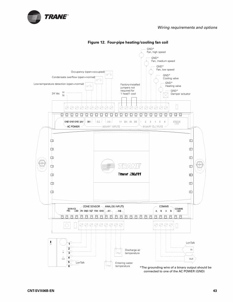
Figure 12. Four-pipe heating/cooling fan coil
GND*Fan, medium speed
GND*Fan, low speed
GND*Cooling valve
GND*Fan, high speed
Low-temperature detection (open=normal)
Condensate overflow (open=normal)
HN
24 VacGND*Damper actuator
GND*Heating valve
LonTalk
in
Entering water temperature
Discharge airtemperature
LonTalkout
*The grounding wire of a binary output should be connected to one of the AC POWER (GND)
Factory-installed jumpers not required for 1 heat/1 cool
Occupancy (open=occupied)
CNT-SVX06B-EN 43

Chapter 6 Applications for the 1 heat/1 cool configuration
Figure 13. Four-pipe fan coil with auto changeover
GND*Fan, medium speed
GND*Fan, low speed
GND*Heating/cooling valve
GND*Fan, high speed
Low-temperature detection (open=normal)
Condensate overflow (open=normal)
HN
24 VacGND*Damper actuator
GND*Heating valve
LonTalk
in
Entering water temperature
Discharge airtemperature
LonTalk
out
*The grounding wire of a binary output should be connected to one of the AC POWER (GND) terminals.
Factory-installed jumpers not required for 1 heat/1 cool
Occupancy (open=occupied)
44 CNT-SVX06B-EN

Wiring requirements and options
Figure 14. Fan coil with electric heat
GND*Fan, medium speed
GND*Fan, low speed
GND*Fan, high speed
Low-temperature detection (open=normal)
Condensate overflow (open=normal)
HN
24 VacGND*Damper actuator
GND*Electric heat (optional)
LonTalk
in
Entering water temperature
Discharge airtemperature
LonTalk
out
*The grounding wire of a binary output should be connected to one of the AC POWER (GND) terminals.
Factory-installed jumpers not required for 1 heat/1 cool
Occupancy (open=occupied)
CNT-SVX06B-EN 45

Chapter 6 Applications for the 1 heat/1 cool configuration
46 CNT-SVX06B-EN

Chapter 7
Sequence of operations for
the 1 heat/1 cool
configuration
A Tracer ZN511 zone controller configured to control a 1 heat/1 cool unit will operate to maintain the zone temperature set point. This chapter dis-cusses many of the operational sequences used by the controller to accom-plish this goal.
Power-up sequenceWhen 24 Vac power is initially applied to the Tracer ZN511 zone control-ler, the following sequence occurs:
1. All outputs are controlled off.
2. The controller reads all input local values to determine initial values.
3. The random-start timer begins (see “Random start” on page 48).
4. If a hardwired zone-temperature value is not detected, the controller begins to wait for a communicated value. (This can take several min-utes [15-minute default] and occurs concurrently with the remainder of the power-up sequence.) If a communicated zone-temperature value arrives, normal operation can begin when the power-up sequence has concluded. If a communicated zone-temperature value does not arrive, a Zone Temp Failure diagnostic is generated (normal operation cannot begin without a valid zone-temperature value).
5. The random-start timer expires.
6. The power-up control wait function begins automatically if the config-ured power-up control wait time is greater than zero. When this func-tion is enabled, the controller waits for the configured amount of time (from 0 to 120 seconds) to allow a communicated occupancy request to arrive. If a communicated occupancy request arrives, normal opera-tion can begin. If a communicated occupancy request does not arrive, the controller assumes stand-alone operation.
7. Normal operation begins assuming no diagnostics have been gener-ated.
CNT-SVX06B-EN 47

Chapter 7 Sequence of operations for the 1 heat/1 cool configuration
Random startRandom start is intended to prevent all units in a building from energiz-ing major loads at the same time. The random-start timer delays the fan start-up from 5 to 30 seconds. If neither heating nor cooling is initiated, or if fan operation is not required during the delay, the random-start timer is allowed to time-out.
Zone temperature controlThe Tracer ZN511 zone controller calculates a required heating or cooling capacity (0–100%) according to the measured zone temperature and the active temperature set point, and sequences the fan coil unit heating and cooling stages accordingly. The active temperature set point is deter-mined by the current operating modes, which include occupancy mode and heat/cool mode.
Occupancy modesOccupancy modes can be controlled by any of the following:
• The state of the local (hardwired) occupancy binary input BI3 (see “BI3: Occupancy or generic binary input” on page 15)
• A timed override request from a Trane zone sensor (see “Timed over-ride control” on page 50)
• A communicated signal from a peer device (see “Peer-to-peer (master/slave) data sharing” on page 54)
• A communicated signal from a BAS
A communicated request, either from a BAS or a peer controller, takes precedence over local requests. If a communicated occupancy request has been established and is no longer present, the controller reverts to the default (occupied) occupancy mode after 15 minutes (if no hardwired occu-pancy request exists). The Tracer ZN511 has the following occupancy mode options:
• Occupied• Unoccupied• Occupied standby• Occupied bypass
Occupied mode
In occupied mode, the controller maintains the zone temperature based on the occupied heating or cooling set points. The controller uses the occu-pied mode as a default mode when other forms of occupancy request are not present. The fan will run as configured (continuous or cycling). The outdoor air damper will close when the fan is off. The temperature set points can be local (hardwired), communicated, or stored default values (configurable in Rover).
48 CNT-SVX06B-EN

Occupancy modes
Unoccupied mode
In unoccupied mode, the controller attempts to maintain the zone temper-ature based on the unoccupied heating or cooling set point. The fan will cycle between high speed and off. The outdoor air damper will remain closed. The controller always uses the stored default set-point values (configurable in Rover), regardless of the presence of a hardwired or com-municated set-point value.
Occupied standby mode
The controller is placed in occupied standby mode only when a communi-cated occupied request is combined with an unoccupied request from occupancy binary input BI3. In occupied standby mode, the controller maintains the zone temperature based on the occupied standby heating or cooling set points. Because the occupied standby set points are typi-cally spread 2°F (1.1°C) in either direction and the outdoor air damper is closed, this mode reduces the demand for heating and cooling the space. The fan will run as configured (continuous or cycling) for occupied mode. The controller always uses the stored default set-point values (config-urable in Rover), regardless of hardwired or communicated set-point val-ues.
Occupied bypass mode
The controller is placed in occupied bypass mode when the controller is operating in the unoccupied mode and either the timed override ON but-ton on the Trane zone sensor is pressed or the controller receives a com-municated occupied bypass signal from a BAS. In occupied bypass mode, the controller maintains the zone temperature based on the occupied heating or cooling set points. The fan will run as configured (continuous or cycling). The outdoor air damper will close when the fan is off. The con-troller will remain in occupied bypass mode until either the CANCEL button is pressed on the Trane zone sensor or the occupied bypass time (configurable in Rover) expires. The temperature set points can be local (hardwired), communicated, or stored default values (configurable in Rover).
CNT-SVX06B-EN 49

Chapter 7 Sequence of operations for the 1 heat/1 cool configuration
Timed override controlIf the zone sensor has a timed override option (ON/CANCEL buttons), pushing the ON button momentarily shorts the zone temperature signal to the controller. This short is interpreted as a timed override on request. A timed override on request changes the occupancy mode from unoccu-pied mode to occupied bypass mode. In occupied bypass mode, the control-ler controls the zone temperature based on the occupied heating or cooling set points. The occupied bypass time, which resides in the Tracer ZN511 and defines the duration of the override, is configurable through the Rover service tool from 0 to 240 minutes (default value of 120 min-utes). When the occupied bypass time expires, the unit transitions from occupied bypass mode to unoccupied mode. Pushing the CANCEL button momentarily sends a fixed resistance of 1.5 kΩ to the ZN analog input of the controller, which is interpreted as a timed override cancel request. A timed override cancel request will end the timed override before the occu-pied bypass time has expired and will transition the unit from occupied bypass mode to unoccupied mode.
If the controller is in any mode other than unoccupied when the ON but-ton is pressed, the controller still starts the occupied bypass timer with-out changing the mode to occupied bypass. If the controller is placed in unoccupied mode before the occupied bypass timer expires, the controller will be placed in occupied bypass mode and remain in that mode until either the CANCEL button is pressed on the Trane zone sensor or the occupied bypass time expires.
Morning warm-upThe morning warm-up feature is initiated when the controller is in tran-sition from unoccupied to occupied and the zone temperature is 3°F (1.7°C) below the occupied heating set point. The fan will be turned on and the outdoor air damper will remain closed. When the zone tempera-ture reaches the occupied heating set point, the controller begins operat-ing in the occupied mode.
Morning cool-downThe morning cool-down feature is initiated when the controller is in tran-sition from unoccupied to occupied and the zone temperature is 3°F (1.7°C) above the occupied heating set point. The fan will be turned on and the outdoor air damper will remain closed. When the zone tempera-ture reaches the occupied heating set point, the controller begins operat-ing in the occupied mode.
50 CNT-SVX06B-EN
Heating or cooling mode
Heating or cooling modeThe heating or cooling mode can be determined in one of two ways:
• By a communicated signal from a BAS or a peer controller• Automatically, as determined by the controller
A communicated heating signal permits the controller to heat only. A communicated cooling signal permits the controller to cool only. A com-municated auto signal allows the controller to automatically change from heating to cooling and vice versa.
In heating and cooling mode, the controller maintains the zone tempera-ture based on the active heating set point and the active cooling set point, respectively. The active heating and cooling set points are determined by the occupancy mode of the controller.
For two-pipe and four-pipe changeover units, normal heat/cool operation will not begin until the ability to conduct the desired heating or cooling operation is verified. This is done using the entering water temperature sampling function (see “AI1: Entering water temperature sampling” on page 37), for which a valid entering water temperature is required. When neither a hardwired nor a communicated entering water temperature value is present on changeover units, the controller will operate in heat-ing mode only (assuming the water is hot), and the sampling function is not used.
For 1 heat/1 cool units that are not changeover applications, whether the entering water temperature is hot or cold is dependent on the configura-tion of the unit. For these applications, the entering water sampling func-tion is not used. The entering water temperature value is used for information and troubleshooting only and does not affect the operation of the controller.
Entering water temperature sampling
functionThe entering water temperature sampling function is used with two-pipe and four-pipe changeover units and requires a valid entering water tem-perature value. If the entering water temperature value is less than 5°F (2.8°C) above a valid zone temperature value for hydronic heating and greater than 5°F (2.8°C) below a valid zone temperature value for hydronic cooling, the sampling function is enabled. When the sampling function is enabled, the controller opens the main hydronic valve to allow the water temperature to stabilize. After 3 minutes, the controller again compares the entering water temperature value to the zone temperature value to determine if the desired heating or cooling function can be accomplished.
CNT-SVX06B-EN 51
Chapter 7 Sequence of operations for the 1 heat/1 cool configuration
If the entering water temperature value remains out of range to accom-plish the desired heat/cool function, the controller closes the main hydronic valve and waits 60 minutes to attempt another sampling. If the entering water temperature value falls within the required range, it resumes normal heating/cooling operation and disables the sampling function.
Fan operation and statusThe Tracer ZN511, configured for 1 heat/1 cool operation, supports three fan speeds. Every time the fan is enabled, the fan will begin operation and run for 3 seconds in high speed before changing to any other speed. This is done to provide adequate torque to start the fan motor from the off position. The controller can be set to Auto, a specific fan speed, or Off. If both a communicated and hardwired value is present, the communicated value has priority.
When the controller receives a communicated Auto signal or the associ-ated fan speed switch is set to AUTO, the fan will operate in the Auto mode. In the Auto mode, the fan will operate as configured in Rover. The fan can be configured for continuous or cycling operation and for a default fan speed for both heating and cooling mode operation. When configured for continuous operation, the fan operates continuously at the default fan speed during occupied, occupied standby and occupied bypass operation. When configured for cycling operation, the fan will cycle between off and the default fan speed during occupied, occupied standby, and occupied bypass operation. During unoccupied operation, the fan will cycle between off and high regardless of the fan configuration.
When the controller receives a communicated fan speed signal (high, medium, low) or the associated fan speed switch is set to a specific fan speed, the fan will run continuously at the desired fan speed during occu-pied, occupied standby, and occupied bypass operation. During unoccu-pied operation, the fan will cycle between off and high regardless of the fan configuration.
The fan will turn off when the controller receives a communicated off sig-nal, when the fan speed switch is set to OFF, or when the default fan speed is set to off and the fan is operating in the auto mode.
The ability to enable or disable the controller’s associated fan speed switch is also configurable.
52 CNT-SVX06B-EN

Two-position valve operation
Two-position valve operationThe Tracer ZN511 zone controller will control hydronic, two-position valves for any of the 1 heat/1 cool applications shown in Table 12.
The controller opens and closes the appropriate value to control the zone temperature at the heating set point in heating mode or at the cooling set point in cooling mode.
Two-pipe operation
For two-pipe applications, the Tracer ZN511 can be configured as heating only, cooling only, or heat/cool changeover (see Table 12). The main coil can be used as the primary heating source and/or the primary cooling source. If present, an electric heating element can only be used as the pri-mary heating source, not as a second stage of heating. A changeover unit requires a valid entering water temperature value—either communicated or hardwired—to operate properly. The entering water temperature value, along with the entering water temperature sampling function, allows a changeover unit to accurately and reliably control zone tempera-ture. When there is not a valid entering water temperature present for a changeover unit, the controller will operate only in heating mode and the water will be assumed hot.
Four-pipe operation
For four-pipe applications, the Tracer ZN511 can be configured as heat/cool or heat/cool changeover (see Table 12). The main coil can be used as the primary cooling source or the primary heating/cooling source. The auxiliary coil can only be used as the primary heating source, not as a sec-ond stage of heating. During normal operation, the controller never uses the main coil and auxiliary coil simultaneously. A changeover unit requires a valid entering water temperature value—either communicated or hardwired—to operate properly. The entering water temperature value, along with the entering water temperature sampling function, allows the changeover unit to accurately and reliably control zone tem-perature. When there is not a valid entering water temperature present for a changeover unit, the controller will only operate in heating mode and the water will be assumed hot.
Table 12. Configuration options for 1 heat/1 cool applications
Application Main coilAuxiliary
coilElectric heat
option?
2-pipe cooling only Cool N/A Yes
2-pipe heating only Heat N/A No
2-pipe heat/cool changeover Heat/Cool N/A Yes
4-pipe heating and cooling Cool Heat No
4-pipe main coil changeover Heat/Cool Heat No
CNT-SVX06B-EN 53

Chapter 7 Sequence of operations for the 1 heat/1 cool configuration
Electric heat operation
The Tracer ZN511 supports a single stage of electric heat for 2-pipe appli-cations (see Table 12). Electric heat can only be used as the primary heat source, not as a second stage of heating. Electric heat is cycled on and off to maintain zone temperature at the active heating set point.
Outdoor air damper operationThe Tracer ZN511 supports a two-position outdoor air damper. The damper is used as a source for ventilation air only, not as a cooling source (economizer). In occupied and occupied standby mode, the damper is open when the fan is on and closed when the fan is off. In occupied standby and unoccupied mode, as well as during morning warm-up and morning cool-down, the damper remains closed.
Peer-to-peer (master/slave) data
sharingTracer ZN511 zone controllers have the ability to share data with other LonTalk-based controllers. Several controllers can be bound as peers, using the Rover service tool, to share:
• Set point• Zone temperature• Heating/cooling mode• Fan status• Unit capacity control
Shared data is communicated from the controller assigned as master to the other (slave) controllers. Applications having more than one unit serv-ing one zone can benefit by using this feature, which prevents multiple units from simultaneously heating and cooling.
54 CNT-SVX06B-EN

Unit protection strategies
Unit protection strategiesThe following strategies are initiated when specific conditions exist in order to protect the unit or building from damage:
• Smart reset• High/low pressure cutout• Low-temperature protection• Condensate overflow• Filter maintenance timer
Smart reset
The Tracer ZN511 will automatically restart a unit that is locked-out as a result of a Low Temp Detection Circuit 1 (BI1) diagnostic. Referred to as “smart reset,” this automatic restart will occur 30 minutes after the diag-nostic occurs. If the unit is successfully restarted, the diagnostic is cleared. If the unit undergoes another smart reset diagnostic within a 24-hour period, the unit will be locked out until it is manually reset. For more information on manual resetting, see “Manual (latching) diagnos-tics” on page 66).
Low-temperature protection
See “BI1: Low-temperature detection” on page 34.
Condensate overflow
See “BI2: Condensate overflow” on page 34.
Filter-maintenance timer
The filter-maintenance timer tracks the amount of time (in hours) that the fan is enabled. The Maintenance Required Timer Setpoint, configured with the Rover service tool, is used to set the amount of time until main-tenance (typically, a filter change) is needed. If the set point is configured to zero, the filter-maintenance timer is disabled.
The controller compares the fan-run time to Maintenance Required Timer Setpoint. Once the set point is reached, the controller generates a Mainte-nance Required diagnostic. When the diagnostic is cleared, the controller resets the filter-maintenance timer to zero, and the timer begins accumu-lating fan-run time again.
Fan off delay
After heating has been controlled off, the Tracer ZN511 automatically keeps the fan energized for an additional 30 seconds. The purpose of this feature is to remove residual heat from the heating source.
CNT-SVX06B-EN 55

Chapter 7 Sequence of operations for the 1 heat/1 cool configuration
56 CNT-SVX06B-EN

Chapter 8
Status indicators for
operation and
communication
This chapter describes the operation and communication status indica-tors on the Tracer ZN511 controller, including:
• A description of the location and function of the Test button and Ser-vice button (pin) and the light-emitting diodes (LEDs) located on the controller
• A complete list of the diagnostics that can occur, their effect on con-troller outputs, and an explanation of how diagnostics are cleared and the device restored to normal operation
Test buttonThe Test button is used to perform the manual output test (see “Manual output test” on page 58), which verifies that the controller is operating properly. It is located as shown in Figure 15.
Figure 15. Tracer ZN511 zone controller circuit board
Yellow LED
Neuron chip
Red LED
Green LED
Test button
Service button
Neuron ID label
CNT-SVX06B-EN 57

Chapter 8 Status indicators for operation and communication
Manual output testThe manual output test sequentially turns off and on all binary outputs to verify their operation. The test overrides normal operation of the con-troller, which is suspended while the test is being performed.
Use the manual output test to:
• Verify output wiring and operation• Force compressor operation (on heat pumps) so that a technician can
use test equipment to verify unit operation.• Force the water valve open (on 1 heat/1 cool units) to balance the
hydronic system• Clear diagnostics and restore normal operation (although not a pri-
mary function of the manual output test)
The manual output test is performed either by repeatedly pressing the Test button to proceed through the test sequence or by using the Rover service tool. Table 13 on page 59 lists the outputs for heat pump configu-rations in the sequence in which they are verified; Table 14 on page 59 lists the outputs for 1 heat/1 cool configurations in the sequence in which they are verified. The procedure is as follows:
1. Press and hold the Test button for 3 to 4 seconds, then release the pin to start the test mode. The green LED light goes off when the Test button is pressed, and then it blinks (as described in Table 16 on page 60) when the pin is released to indicate the controller is in man-ual test mode.
2. Press the Test button (no more than once per second) to advance through the test sequence. Table 13 shows the resulting activities of the binary outputs.
Service button (pin)The Service button (pin) is located as shown in Figure 15 on page 57. The Service button is used to:
• Identify a device (see “Identifying a device” in the Rover Installation/Operation/Programming guide (EMTX-SVX01A-EN)
• Add a device to the active group (see “Adding a device” in EMTX-SVX01A-EN)
• Verify PCMCIA communications (see “Verifying PCMCIA communi-cations” in EMTX-SVX01A-EN)
• Make the green LED “wink” to verify that the controller is communi-cating on the link (see Table 16 on page 60 and “Setting the Auto-wink option” in EMTX-SVX01A-EN)
Note:
The outputs are not subject to minimum on or off times during the test sequence. However, the test sequence permits only one step per second, which enforces a minimum output time.
58 CNT-SVX06B-EN

Service button (pin)
Table 13. Manual output test sequence for water-source heat pump configurations
Step (number of times Test button is
pressed in sequence)
Result Fan (BOP1)Reversing
valve (BOP2)Comp. 1 (BOP4)
Comp. 2 (BOP5)
Damper/Generic (BOP6)
1 Begins test mode Off Off Off Off Closed/Off
2 Fan on1 On Off Off Off Closed/Off
3 Reversing valve on On On Off Off Closed/Off
4 Compressor 1 On On On Off Closed/Off
5 Compressor 22 On On On On Closed/Off
6 Compressor(s) off3 On Off Off Off Closed/Off
7 Heat 1 On Off On Off Closed/Off
8 Heat 22 On Off On On Closed/Off
9 Outdoor air damper4 On Off Off Off Open/On
10 Exit5
1 At the beginning of Step 2, the controller attempts to clear all diagnostics.2 BOP5 will be controlled during this step regardless of its configuration.3 This stage helps avoid an abrupt transition from cooling to heating by turning off the compressors prior to changing the
reversing valve state.4 BOP6 will be controlled during this step regardless of its configuration.5 This step will exit the manual output test and initiate a reset to restore the controller to normal operation.
Table 14. Manual output test sequence for 1 heat/1 cool configurations
Step (number of times Test
button is pressed in sequence)
ResultFan high (BOP1)
Fan medium (BOP2)
Fan low (BOP3)
Cool output (BOP4)1
Heat output (BOP5)1
Damper/Generic (BOP6)
1 Begins test mode Off Off Off Off Off Closed/Off
2 Fan high2 On Off Off Off Off Closed/Off
3 Fan medium Off On Off Off Off Closed/Off
4 Fan low Off Off On Off Off Closed/Off
5 Cool On Off Off On Off Closed/Off
6 Heat On Off Off Off On Closed/Off
7 Outdoor air damper3 On Off Off Off Off Open/On
8 Exit4
1 For all 1 heat/1 cool applications including 2-pipe changeover, BOP4 energizes in the cool test stage and BOP5 energizes in the heat test state, even though during normal unit operation BOP4 may control the unit valve for both cooling and heating (2-pipe changeover).
2 At the beginning of Step 2, the controller attempts to clear all diagnostics.3 BOP6 will be controlled during this step regardless of its configuration.4 This step will exit the manual output test and initiate a reset to restore the controller to normal operation.
CNT-SVX06B-EN 59

Chapter 8 Status indicators for operation and communication
Interpreting LEDsThe red LED on the Tracer ZN511 controller (see Figure 15 on page 57) indicates whether the controller is capable of operating normally (see Table 15).
The green LED on the Tracer ZN511 controller (see Figure 15 on page 57) indicates whether the controller has power applied to it and if the control-ler is in manual test mode (see Table 16).
Table 15. Red LED: Service indicator
LED activity Explanation
LED is off continuously when power is applied to the controller.
The controller is operating normally.
LED is on continuously when power is applied to the controller.
The controller is not working prop-erly, or someone is pressing the Ser-vice button.
LED flashes once every second. The controller is not executing the application software because the net-work connections and addressing have been removed.1
1 Restore the controller to normal operation using the Rover service tool. Refer to EMTX-SVX01A-EN for more information.
Table 16. Green LED: Status indicator
LED activity Explanation
LED is on continuously. Power is on (normal operation).
LED blinks (one recurring blink). Manual output test mode is being performed and no diagnostics are present.
LED blinks (blinks twice as a recur-ring sequence).
Manual output test mode is being performed and one or more diag-nostics are present.
LED blinks (1/4 second on, 1/4 second off for 10 seconds).
The Auto-wink option is activated, and the controller is communicat-ing.1
LED is off continuously. Either the power is off, the controller has malfunctioned, or the Test button is being pressed.
1 By sending a request from the Rover service tool, you can request the controller’s green LED to blink (“wink”), a notification that the controller received the signal and is communicating.
60 CNT-SVX06B-EN
Interpreting LEDs
The yellow LEDs on the Tracer ZN511 controller (see Figure 15 on page 57) indicate the controller’s communications status (see Table 17).
Table 17. Yellow LED: Communications indicator
LED activity Explanation
LED is off continuously The controller is not detecting any communication (normal for stand-alone applications).
LED blinks. The controller detects communica-tion (normal for communicating applications, including data sharing).
LED is on continuously. Abnormal condition.
CNT-SVX06B-EN 61

Chapter 8 Status indicators for operation and communication
DiagnosticsIn response to a diagnostic, the controller attempts to protect the equip-ment by activating or de-activating, or opening or closing, certain outputs. Table 18 on page 62 and Table 19 on page 64 list diagnostics that can occur with the Tracer ZN511 controller. The tables present each diagnos-tic that can be generated, its effect on outputs (consequences), and its type (categorized according to clearing method).
Note:
The generic binary output is unaffected by diagnostics.
Table 18. Diagnostics for heat pump configurations
Diagnostic Probable cause ConsequencesDiagnostic
type1
Maintenance Required Fan run hours exceed the time set to indicate filter change
Fan unaffectedValves unaffectedElectric heat unaffectedDamper unaffected
Informational
Condensate Overflow The drain pan is full of water
Fan offValves closedElectric heat offCompressors offDamper closed
Manual
Low Temp Detection Circuit 1
The leaving fluid tempera-ture is close to freezing
Fan unaffected2
Compressor 1 offCompressor 22
Damper2
Smart reset/Manual
Low Temp Detection Circuit 2
The leaving fluid tempera-ture is close to freezing
Fan unaffected2
Compressor 12
Compressor 2 offDamper2
Smart reset/Manual
Low Temp Detection Circuits 1 and 2
The leaving fluid tempera-ture is close to freezing
Fan offCompressor 1 offCompressor 2 offDamper closed
Smart reset/Manual
High/Low Pressure Cutout Circuit 1
Abnormal refrigerant pres-sures
Fan unaffected2
Compressor 1 offCompressor 22
Damper2
Smart reset/Manual
High/low Pressure Cutout Circuit 2
Abnormal refrigerant pres-sures
Fan unaffectedCompressor 12
Compressor 2 offDamper2
Smart reset/Manual
1 For more information on types of diagnostics and how they are cleared from the controller, see “Clearing diagnostics” on page 66.
2 High/low pressure cutout and low temperature detection diagnostics for water-source heat pump configurations isolate each circuit and independently disable compressor operation. For single compressor units, these diagnostics cause the compressor to shut down, the unit fan to be controlled off, and the outdoor air damper to be closed (when present).
62 CNT-SVX06B-EN

Diagnostics
High/Low Pressure Cutout Circuits 1 and 2
Abnormal refrigerant pres-sures
Fan offCompressor 1 offCompressor 2 offDamper closed
Smart reset/Manual
Zone Temp Failure Invalid or missing value for zone temperature
Fan off2
Valves closedElectric heat offCompressors offDamper closed
Automatic
Leaving Water Temp Failure Invalid or missing value for zone temperature
Fan unaffected2
Compressor 1 offCompressor 22
Damper2
Manual
Discharge Air Temp Failure Invalid or missing value for zone temperature
Fan unaffectedValves unaffectedElectric heat unaffectedCompressors unaffectedDamper unaffected
Automatic
Setpoint Failure Invalid or missing value for zone set point
Fan unaffectedValves unaffectedElectric heat unaffectedCompressors unaffectedDampers unaffected
Automatic
Fan Mode Failure Invalid or missing value for fan mode switch resistance
Fan unaffectedValves unaffectedElectric heat unaffectedCompressors unaffectedDamper unaffected
Automatic
Invalid Unit Configuration Software configuration is done improperly
Fan offValves closedElectric heat offCompressors offDamper closed
Manual
Normal—Power Up On start-up Fan unaffectedValves unaffectedElectric heat unaffectedCompressors unaffectedDamper unaffected
Automatic
Table 18. Diagnostics for heat pump configurations (Continued)
Diagnostic Probable cause ConsequencesDiagnostic
type1
1 For more information on types of diagnostics and how they are cleared from the controller, see “Clearing diagnostics” on page 66.
2 High/low pressure cutout and low temperature detection diagnostics for water-source heat pump configurations isolate each circuit and independently disable compressor operation. For single compressor units, these diagnostics cause the compressor to shut down, the unit fan to be controlled off, and the outdoor air damper to be closed (when present).
CNT-SVX06B-EN 63

Chapter 8 Status indicators for operation and communication
Table 19. Diagnostics for 1 heat/1 cool configurations
Diagnostic Probable cause Consequences Diagnostic type1
Maintenance Required Fan run hours exceed the time set to indicate filter change
Fan unaffectedValves unaffectedElectric heat unaffectedDamper unaffected
Informational
Condensate Overflow The drain pan is full of water
Fan offValves closedElectric heat offCompressors offDamper closed
Manual
Low Temp Detection The leaving fluid temper-ature is close to freezing
Fan offValves openElectric heat offDamper closed
Smart reset/Manual
Zone Temp Failure Invalid or missing value for zone temperature
Fan offValves closedElectric heat offCompressors offDamper closed
Automatic
Entering Water Temp Failure
Invalid or missing value for zone temperature
Fan unaffectedValves unaffected2
Electric heat unaffected2
Damper unaffected2
Automatic
Discharge Air Temp Failure
Invalid or missing value for zone temperature
Fan unaffectedValves unaffectedElectric heat unaffectedDamper unaffected
Automatic
Setpoint Failure Invalid or missing value for zone set point
Fan unaffectedValves unaffectedElectric heat unaffectedDamper unaffected
Automatic
Fan Mode Failure Zone set point Fan unaffectedValves unaffectedElectric heat unaffectedCompressors unaffectedDamper unaffected
Automatic
Invalid Unit Configura-tion
Software configuration is done improperly
Fan offValves closedElectric heat offCompressors offDamper closed
Manual
1 For more information on types of diagnostics and how they are cleared from the controller, see “Clearing diagnos-tics” on page 66.
2 When the entering water temperature is required but not present, the 1 heat/1 cool unit generates a diagnostic to indicate the sensor loss condition. The controller automatically clears the diagnostics once a valid entering water temperature value is present (nonlatching diagnostic). When the entering water temperature fails, the controller pro-hibits all cooling operating, but allows the delivery of heat when heating is required. In cool mode, all cooling is locked out, but normal fan and damper operation is permitted.
64 CNT-SVX06B-EN

Diagnostics
Normal—Power Up On start-up Fan unaffectedValves unaffectedElectric heat unaffectedCompressors unaffectedDamper unaffected
Automatic
Table 19. Diagnostics for 1 heat/1 cool configurations (Continued)
Diagnostic Probable cause Consequences Diagnostic type1
1 For more information on types of diagnostics and how they are cleared from the controller, see “Clearing diagnos-tics” on page 66.
2 When the entering water temperature is required but not present, the 1 heat/1 cool unit generates a diagnostic to indicate the sensor loss condition. The controller automatically clears the diagnostics once a valid entering water temperature value is present (nonlatching diagnostic). When the entering water temperature fails, the controller pro-hibits all cooling operating, but allows the delivery of heat when heating is required. In cool mode, all cooling is locked out, but normal fan and damper operation is permitted.
CNT-SVX06B-EN 65
Chapter 8 Status indicators for operation and communication
Clearing diagnostics
Diagnostics are categorized according to the type of clearing function each has. The four categories are:
• Manual (latching)• Automatic (nonlatching)• Smart reset • Informational
Manual (latching) diagnostics
Manual diagnostics (also referred to as latching) cause the unit to shut down. Manual diagnostics can be cleared from the controller in one of the following ways:
• By using the Rover service tool (see “Resetting a diagnostic” in EMTX-SVX01A-EN, Rover Installation, Operation, and Programming guide.)
• Through a building automation system (see product literature)• By initiating a manual output test at the controller (see “Manual out-
put test” on page 58)• By cycling power to the controller. When the 24 Vac power to the con-
troller is cycled off and then on again, a power-up sequence occurs.• By turning the zone sensor fan switch to OFF and then back on to any
other setting. (This feature will be available beginning with controller software version 2.10.)
Automatic (nonlatching) diagnostics
Automatic diagnostics clear automatically when the problem that gener-ated the diagnostic is solved.
Smart reset diagnostics
After the controller detects the first smart reset diagnostic, the unit waits 30 minutes before initiating the smart reset function. If another diagnos-tic of this type occurs again within 24 hours after an automatic clearing, you must manually clear the diagnostic.
Informational diagnostics
Informational diagnostics provide information about the status of the controller. They do not affect machine operation. They can be cleared from the controller in the same ways that manual diagnostics are cleared (see “Manual (latching) diagnostics” on page 66).
Note:
Clearing diagnostics refers to deleting diagnostics from the software; it does not affect the problem that generated the mes-sage. For help with diagnosing a problem, see Chapter 9, “Trou-bleshooting”.
66 CNT-SVX06B-EN

Chapter 9
Troubleshooting
Use Table 20 through Table 25 to assist you in diagnosing any of the fol-lowing operational problems that you might encounter with the Tracer ZN511 zone controller:
• Fan does not energize (Table 20)• Valves remain closed (Table 21 on page 68)• Valves remain open (Table 22 on page 68)• Compressors are not running (Table 23 on page 69)• Electric heat does not energize (Table 23 on page 69)• An outdoor air damper stays closed (Table 24 on page 70)• An outdoor air damper stays open (Table 25 on page 70)
Table 20. Fan does not energize
Probable cause Explanation
Unit wiring The wiring between the controller outputs and the fan relays and contacts must be present and correct for normal fan operation. Refer to applicable wiring diagram.
Failed end device The fan motor and relay must be checked to ensure proper operation
Random start observed
After power-up, the controller always observes a random start from 0 to 25 seconds. The controller remains off until the random start time expires.
Power-up control-wait If power-up control-wait is enabled (non-zero time), the controller remains off until one of two conditions occurs:1) The controller exits power-up control-wait once it receives communicated information.2) The controller exits power-up control-wait once the power-up control-wait time expires.
Cycling fan operation If configured to cycle with capacity, normally the fan cycles off with heating or cooling. The heating/cooling sources cycle on or off periodically with the fan to provide varying amounts of capacity to the zone.
Unoccupied operation Even if the controller is configured for continuous fan operation, the fan normally cycles with capacity during unoccupied mode. While unoccupied, the fan cycles on or off with heating/cooling to provide varying amounts of heating or cooling to the space.
Fan mode off If a local fan mode switch determines the fan operation, the off position controls the fan off.
Requested mode off You can communicate a desired operating mode (such as off, heat, and cool) to the con-troller. If off is communicated to the controller, the unit controls the fan off. There is no heating or cooling.
Diagnostic present A specific list of diagnostics affects fan operation, depending on whether the unit is con-figured as 1 heat/1 cool or a water-source heat pump. For more information, see Table 18 on page 62 and Table 19 on page 64.
No power to the con-troller
If the controller does not have power, the unit fan does not operate. For the Tracer ZN511 controller to operate normally, it must have an input voltage of 24 Vac. If the green LED is off continuously, the controller does not have sufficient power or has failed.
CNT-SVX06B-EN 67

Chapter 9 Troubleshooting
Unit configuration The controller must be properly configured based on the actual installed end devices and application (1 heat/1 cool or water-source heat pump). If the unit configuration does not match the actual end device, the valves may not work correctly.
Manual output test The controller includes a manual output test sequence you can use to verify output oper-ation and associated output wiring. However, based on the current step in the test sequence, the unit fan may not be on. Refer to the “Manual output test” on page 58.
Table 21. Valves remain closed
Probable cause Explanation
Unit wiring The wiring between the controller outputs and the valve(s) must be present and correct for normal valve operation. Refer to applicable wiring diagram.
Failed end device The valves must be checked to ensure proper operation.
Normal operation The controller opens and closes the valves to meet the unit capacity requirements.
Requested mode off You can communicate a desired operating mode (such as off, heat, and cool) to the con-troller. If off is communicated to the controller, the unit controls the fan off. There is no heating or cooling.
Manual output test The controller includes a manual output test sequence you can use to verify output oper-ation and associated output wiring. However, based on the current step in the test sequence, the valves may not be open. Refer to the “Manual output test” on page 58.
Diagnostic present A specific list of diagnostics affects valve operation, dependent on whether the unit is configured as 1 heat/1 cool or a water-source heat pump. For more information, see Table 18 on page 62 and Table 19 on page 64.
Entering water temperature sampling logic
The controller includes entering water temperature sampling logic, which is automati-cally initiated during 2-pipe and 4-pipe changeover if the entering water temperature is either too cool or too hot for the desired heating or cooling. (See “AI1: Entering water temperature sampling” on page 37.)
Unit configuration The controller must be properly configured based on the actual installed end devices and application (1 heat/1 cool or water-source heat pump). If the unit configuration does not match the actual end device, the valves may not work correctly.
Valve configuration Make sure the valves are correctly configured, using the Rover service tool, as normally open or normally closed as dictated by the application.
No power to the con-troller
If the controller does not have power, the unit valve(s) will not operate. For the ZN511 controller to operate normally, you must apply an input voltage of 24 Vac. If the green LED is off continuously, the controller does not have sufficient power or has failed.
Table 22. Valves remain open
Probable cause Explanation
Unit wiring The wiring between the controller outputs and the valve(s) must be present and correct for normal valve operation. Refer to applicable wiring diagram.
Failed end device The valves must be checked to ensure proper operations.
Normal operation The controller opens and closes the valves to meet the unit capacity requirements.
Table 20. Fan does not energize (Continued)
Probable cause Explanation
68 CNT-SVX06B-EN

Troubleshooting
Manual output test The controller includes a manual output test sequence you can use to verify output oper-ation and associated output wiring. However, based on the current step in the test sequence, the values may not be open. refer to the “Manual output test” on page 58.
Diagnostic present A specific list of diagnostics affects valve operation, depending whether the unit is config-ured as 1 heat/1 cool or a water-source heat pump. For more information, see Table 18 on page 62 and Table 19 on page 64.
Entering water temperature sampling logic
The controller includes entering water temperature sampling logic, which is automatically initiated during 2-pipe and 4-pipe changeover if the entering water temperature is either too cool or too hot for the desired heating or cooling. (See “AI1: Entering water tempera-ture sampling” on page 37.)
Unit configuration The controller must be properly configured based on the actual installed end devices and application (1 heat/1 cool or water-source heat pump). If the unit configuration does not match the actual end device, the valves may not work correctly.
Valve configuration Make sure the valves are correctly configured, using the Rover service tool, as normally open or normally closed as dictated by the application.
Table 23. Electric heat does not energize
Probable cause Explanation
Unit wiring The wiring between the controller outputs and the electric heat contacts must be present and correct for normal electric heat operation. Refer to applicable wiring diagram.
Failed end device Check electric heat element, including any auxiliary safety interlocks, to ensure proper operation.
Normal operation The controller controls electric heat on and off to meet the unit capacity requirements.
Requested mode off You can communicate a desired operating mode (such as off, heat, and cool) to the con-troller. If off is communicated to the controller, the unit shuts off all electric heat.
Communicated dis-able
Numerous communicated requests may disable electric heat, including an auxiliary heat enable input and the heat/cool mode input. Depending on the state of the communicated request, the unit may disable electric heat.
Manual output test The controller includes a manual output test sequence you can use to verify output oper-ation and associated output wiring. However, based on the current step in the test sequence, the electric heat may not be on. Refer to the “Manual output test” on page 58.
Diagnostic present A specific list of diagnostics affects electric heat operation, depending whether the unit is configured as 1 heat/1 cool or a water-source heat pump. For more information, see Table 18 on page 62 and Table 19 on page 64.
Unit configuration
The controller must be properly configured based on the actual installed end devices and application (1 heat/1 cool only). If the unit configuration does not match the actual end device, the electric heat may not work correctly.
No power to the con-troller
If the controller does not have power, electric heat does not operate. For the ZN511 con-troller to operate normally, you must apply an input voltage of 24 Vac. If the green LED is off continuously, the controller does not have sufficient power or has failed.
Table 22. Valves remain open
Probable cause Explanation
CNT-SVX06B-EN 69

Chapter 9 Troubleshooting
Table 24. Outdoor air damper remains closed
Probable cause Explanation
Unit wiring The wiring between the controller outputs and the outdoor air damper must be present and correct for normal outdoor air damper operation. Refer to applicable wiring diagram.
Failed end device Check damper actuator to ensure proper operation.
Normal operation
The controller opens and closes the outdoor air damper based on the controller’s occu-pancy mode and fan status. Normally, the outdoor air damper is open during occupied mode when the fan is running and closed during unoccupied mode.
Warm up and cool down
The controller includes both a morning warm up and cool down sequence to keep the outdoor air damper closed during the transition from unoccupied to occupied. This is an attempt to bring the space under control as quickly as possible.
Requested mode off You can communicate a desired operating mode (such as off, heat, or cool) to the control-ler. If off is communicated to the controller, the unit closes the outdoor air damper.
Manual output test The controller includes a manual output test sequence you can use to verify output oper-ation and associated output wiring. However, based on the current step in the test sequence, the outdoor air damper may not be open. Refer to the “Manual output test” on page 58.
Diagnostic present A specific list of diagnostics affect outdoor air damper operation, depending whether the unit is configured as 1 heat/1 cool or a water-source heat pump. For more information, see Table 18 on page 62 and Table 19 on page 64.
Unit configuration The controller must be properly configured based on the actual installed end devices and application (1 heat/1 cool or water-source heat pump). If the unit configuration does not match the actual end device, the outdoor air damper may not work correctly.
No power to the controller
If the controller does not have power, the outdoor air damper does not operate. For the ZN511 controller to operate normally, you must apply an input voltage of 24 Vac. If the green LED is off continuously, the controller does not have sufficient power or has failed.
Table 25. Outdoor air damper remains open
Probable cause Explanation
Unit wiring The wiring between the controller outputs and the outdoor air damper must be present and correct for normal outdoor air damper operation. Refer to applicable wiring diagram.
Failed end device Check damper actuator to ensure proper operation.
Normal operation
The controller opens and closes the outdoor air damper based on the controller’s occu-pancy mode and fan status. Normally, the outdoor air damper is open during occupied mode when the fan is running and closed during unoccupied mode. (See “Outdoor air damper operation” on page 30 or page 54.
Manual output test The controller includes a manual output test sequence you can use to verify output oper-ation and associated output wiring. However, based on the current step in the test sequence, the outdoor air damper may be open. Refer to the “Manual output test” on page 58.
Unit configuration
The controller must be properly configured based on the actual installed end devices and application (1 heat/1 cool or water-source heat pump). If the unit configuration does not match the actual end device, the outdoor air damper may not work correctly.
70 CNT-SVX06B-EN

CNT-SVX06B-EN
Index
Numerics
1 heat/1 cool configurationAnalog inputs, 35-37Binary inputs, 34-35Binary outputs, 38Condensate overflow input, 34Diagnostics table, 64Discharge air temperature input, 37Electric heat operation, 54Entering water temperature input, 37Entering water temperature
sampling function, 51Fan mode input, 36Fan operation and status, 52Filter-maintenance timer, 55Four-pipe operation, 53Generic binary input, 35Generic binary output, 38Heating or cooling mode, 51Local set-point input, 36Low-temperature detection input, 34Morning cool-down, 50Morning warm-up, 50Occupancy input, 35Occupancy modes, 48Outdoor air damper operation, 54Peer-to-peer data sharing, 54Product description, 1Random start, 48Sequence of operations, 47-55Table of supported applications, 33Timed override control, 50Two-pipe operation, 53Two-position valve operation, 53Unit protection strategies, 55Wiring diagrams, 39-45Zone temperature control, 48Zone temperature input, 36
24 Vac wiring, 8
A
AC power wiring, 8Actuators, valve and damper, 5Additional application-dependent
components, 3-5Agency listing/compliance, 2Analog inputs, 1 heat/1 cool
AI1 (Entering water temperature), 37AI2 (Discharge air temperature), 37FAN (Fan mode input), 36SET (Local set point), 36
ZN (Zone temperature), 36Analog inputs, heat pump
AI1 (Leaving water temperature), 14, 20
AI2 (Discharge air temperature), 21FAN (Fan mode input), 20SET (Local set point), 20ZN (Zone temperature), 19
Applications, 1 heat/1 cool, see 1 heat/1 cool configuration
Applications, heat pump, see Heat pump configuration
B
BAS communication, 1, 9Binary input switching devices, 4Binary inputs, 1 heat/1 cool
BI1 (Low-temperature detection), 34BI2 (Condensate overflow), 34BI3 (Occupancy or generic), 35
Binary inputs, heat pumpBI1 (Low-temperature detection), 14BI2 (Condensate overflow), 15BI3 (Occupancy or generic), 15BI4 and BI5 (High/low pressure
cutout), 16Binary outputs, 1 heat/1 cool
Generic, 38Overriding, 38Table, 38
Binary outputs, heat pumpGeneric, 22Overriding, 22Table, 22
Building automation system communication, 1, 9
C
Cabinet heaters, 33CE, see Agency listing/complianceCircuit board, 57Clearances, 4Compressor contactor monitoring, 16Compressor operation, heat pump
BI4 and BI5 (High/low pressure cutout), 16
Contactor monitoring, 16High/low pressure switch
monitoring, 18Line-voltage monitoring, 18
Condensate overflowDiagnostic, 15, 62, 64Switch, 4, 15, 34Switches, 18
Condensate overflow input1 heat/1 cool configuration, 34
71

Index
Heat pump configuration, 15Configurations
1 heat/1 cool, 1, 33-55Heat pump, 1, 13-32
Current-sensing switches, 4, 18
D
Damper actuators, 5Data sharing, 54Diagnosing operational problems,
67-70Diagnostics
Automatic, 66Categories, 66Clearing, 66Condensate Overflow, 15, 62, 64Discharge Air Temp Failure, 21,
63, 64Entering Water Temp Failure, 64Fan Mode Failure, 20, 63, 64High/Low Pressure Cutout Circuit
1, 16, 62High/Low Pressure Cutout Circuit
2, 16, 62High/Low Pressure Cutout
Circuits 1 and 2, 16, 63Informational, 66Invalid Unit Configuration, 63, 64Latching, 66Leaving Water Temp Failure, 20,
63Low Temp Detection, 64Low Temp Detection Circuit 1, 62Low Temp Detection Circuit 2, 14,
62Low Temp Detection Circuits 1
and 2, 62Maintenance Required, 31, 62Manual, 66Nonlatching, 66Normal—Power Up, 63, 65Setpoint Failure, 20, 63, 64Smart reset, 31, 66Table, 1 heat/1 cool, 64Table, heat pump, 62Zone Temp Failure, 19, 25, 47, 63,
64Dimensional diagram, 3Dimensions, 2Discharge air temperature
diagnostic, 63, 64Discharge air temperature input
1 heat/1 cool configuration, 37Heat pump configuration, 21
E
Electric heat failure, troubleshooting, 69
Electric heat operation, 54Entering water temperature
Diagnostic, 64Input, 37Sampling function, 37, 51
F
Fan coil units, 33Fan mode failure diagnostic, 20, 63,
64Fan mode input
1 heat/1 cool configuration, 36Heat pump configuration, 20
FansOperation and status, 29, 52Troubleshooting, 67
Filter-maintenance timer, 31, 55Four-pipe operation, 53Freeze-protection switch, 4, 14, 16,
18, 34
G
Generic binary input1 heat/1 cool, 35Heat pump, 15
Generic binary output1 heat/1 cool, 38General, 62Heat pump, 22
GND terminal, analog inputs, 19, 35
H
Heat pump configurationAnalog inputs, 19-21Binary inputs, 14-18Binary outputs, 21-22Compressor contactor
monitoring, 16Compressor line-voltage
monitoring, 18Compressor operation, 29Condensate overflow input, 15Diagnostics table, 62Discharge air temperature input,
21Fan mode input, 20Fan operation and status, 29Filter-maintenance timer, 31Generic binary input, 15Generic binary output, 22
Heating or cooling mode, 29High/low pressure cutout input,
16Leaving water temperature input,
20Local set-point input, 20Low-temperature detection input,
14Morning cool-down, 28Morning warm-up, 28Occupancy input, 15Occupancy modes, 26Outdoor air damper operation, 30Peer-to-peer data sharing, 30Product description, 1Random start, 26Reversing valve operation, 30Sequence of operations, 25-32Smart reset, 31Table of supported applications,
13Timed override control, 28Unit protection strategies, 31Wiring diagrams, 22-24Zone temperature control, 26Zone temperature input, 19
Heating or cooling mode1 heat/1 cool configuration, 51Heat pump configuration, 29
High/low pressure cutoutCompressor line-voltage
monitoring, 18Contactor monitoring, 16Diagnostics, 16, 62Inputs, 16Switch monitoring, 18
I
Input/output terminal wiring, 7Inputs, see Analog inputsInputs, see Binary inputs
L
Leaving water temperature(Failure) diagnostic, 20, 63Analog input, 20
LEDsGeneral, 57Interpreting green (status), 60Interpreting red (service), 60Interpreting yellow
(communications), 61Location, 57
Line-voltage monitoring, 18Local set-point input
1 heat/1 cool configuration, 36
72 CNT-SVX06B-EN

Index
Heat pump configuration, 20LonTalk communication
Wiring and addressing specifications, 9
LonTalk protocol, see Product description
Low-temperature detectionDiagnostics, 14, 34, 62, 64
Low-temperature detection input1 heat/1 cool configuration, 34Heat pump configuration, 14
M
Maintenance (filter change) diagnostic, 62, 64
Manual output test, 58Master/slave data sharing, 54Morning cool-down, 28, 50Morning warm-up, 28, 50Mounting
Cover, 12Diagram, 12Location, 11Operating environment, 11Procedures, 12
N
National Electrical Code, 7, 8, 9Neuron IDs
Description, 9Location of label, 57
O
OccupancySwitch, 35Switches, 4, 15
Occupancy input1 heat/1 cool configuration, 35Heat pump configuration, 15
Occupancy modes, 1 heat/1 coolGeneral, 48Occupied, 48Occupied bypass, 49Occupied standby, 49Unoccupied, 49
Occupancy modes, heat pumpGeneral, 26Occupied, 26Occupied bypass, 27Occupied standby, 27Unoccupied mode, 27
Operating environment, 11Outdoor air damper
Operation, 30, 54
Troubleshooting, 70Outputs, see Binary outputsOverriding binary outputs
1 heat/1 cool, 38General, 58Heat pump, 22
P
Peer-to-peer data sharing, 30, 54Power transformers, 4, 8Power wiring, 8Power-up sequence, 25, 47Pressure (abnormal) diagnostics,
16, 62, 63Product description, 1Protection strategies
1 heat/1 cool, 55Heat pump, 31
R
Random start, 26, 48Relays, 5, 21, 38Reversing valve operation, 30Rover service tool, 1, 9
S
SensorsTable of options, 4Water and duct temperature, 4Zone temperature, 4
Sequence of operations, 1 heat/1 cool
Electric heat operation, 54Fan operation and status, 52Filter-maintenance timer, 55Four-pipe operation, 53Heating/cooling mode, 51Morning cool-down, 50Morning warm-up, 50Occupancy modes, 48Outdoor air damper operation, 54Peer-to-peer data sharing, 54Power-up sequence, 47Random start, 48Smart reset, 55Timed override control, 50Two-pipe operation, 53Two-position valve operation, 53Unit protection strategies, 55Zone temperature control, 48
Sequence of operations, heat pumpCompressor operation, 29Fan operation and status, 29Filter-maintenance timer, 31
Heating/cooling mode, 29Morning cool-down, 28Morning warm-up, 28Occupancy modes, 26Outdoor air damper operation, 30Peer-to-peer data sharing, 30Power-up sequence, 25Random start, 26Reversing valve operation, 30Smart reset, 31Timed override control, 28Unit protection strategies, 31Zone temperature control, 26
Service button (pin), 57-58Set-point failure diagnostic, 20, 63,
64Smart reset, 31, 55Specifications
AC power wiring, 8Agency listing/compliance, 2Clearances, 4Dimensional diagram, 3Dimensions, 2Input/output terminal wiring, 7LonTalk communication wiring
and addressing, 9Storage environment, 1Transformers, 8
Status indicators for operation and communication
Diagnostics, 62General, 57Green LEDs, 60Manual output test, 58Red LEDs, 60Service button (pin), 58Test button, 57Yellow LEDs, 61
Storage environment, 1Switches
Condensate overflow, 4, 15, 18, 34
Current sensing, 4, 18Freeze protection, 4, 14, 16, 18, 34Occupancy, 4, 15, 35
T
Temperature sensorsTable of options, 4Water and duct, 4Zone, 4
Termination resistors, 9Test button, 57-58Thermistor, 4, 19, 21, 36, 37Timed override control
1 heat/1 cool, 50Heat pump, 28
Transformers, 4, 8Troubleshooting
CNT-SVX06B-EN 73

Index
Electric heat failure, 69Fans, 67Outdoor air damper, 70Valves, 68
Two-pipe operation, 53Two-position valve operation, 53
U
UL, see Agency listing/complianceUnit protection strategies
1 heat/1 cool configuration, 55Heat pump configuration, 31
V
ValvesActuators, 5Troubleshooting, 68
W
Water and duct temperature sensors, 4
Water-source heat pump, 13Wiring
BAS communication, 9Compliance with National
Electrical Code, 7, 8, 9General, 7-9Input/output terminals, 7LonTalk communication, 9Requirements and options for 1
heat/1 cool configuration, 39Requirements and options for
heat pump configuration, 22Wiring diagrams
1 heat/1 cool configuration, 39-45Heat pump configuration, 22-24
Z
Zone temperature control1 heat/1 cool configuration, 48Heat pump configuration, 26
Zone temperature failure diagnostic, 19, 25, 47, 63, 64
Zone temperature input1 heat/1 cool configuration, 36Heat pump configuration, 19
Zone temperature sensors, 4
74 CNT-SVX06B-EN

Trane has a policy of continuous product and product data improvement and reserves the right to change design and specifications without notice. Only qualified technicians should perform the installa-tion and servicing of equipment referred to in this publication.
Literature Order Number CNT-SVX06B-EN
File Number SV-ES-BAS-CNT-SVX-06B-EN 0405
Supersedes CNT-SVX-06A-EN September 2001
Stocking Location InlandTrane A business of American Standard Companieswww.trane.com
For more information contact your local Traneoffice or e-mail us at [email protected]


