Installation and Operation Manual - Microsoft · Safety light curtain for elevators without car...
68
CEDES © CEDES Version 2.0 / 22.12.05 Part No. 101 090 cegard/Lift LI Safety light curtain for elevators without car doors (non-contact protective device) English Deutsch Français Italiano ISO 9001: 2000 IMPORTANT NOTE FOLLOW THE INSTRUCTIONS GIVEN IN THIS MANUAL CAREFULLY. FAILURE TO DO SO MAY CAUSE CUSTOMER COMPLAINTS AND SERIOUS CALL BACKS. KEEP IN- STRUCTION MANUAL ON SITE. Installation and Operation Manual ...for safer journeys in elevators without car doors
Transcript of Installation and Operation Manual - Microsoft · Safety light curtain for elevators without car...

CEDES
© CEDES Version 2.0 / 22.12.05 Part No. 101 090
cegard/Lift LI
Safety light curtain for elevators without car doors
(non-contact protective device)
English Deutsch Français Italiano
ISO 9001: 2000
IMPORTANT NOTE
FOLLOW THE INSTRUCTIONS GIVEN IN THIS MANUAL CAREFULLY. FAILURE TO DO SO MAY CAUSE CUSTOMER COMPLAINTS AND SERIOUS CALL BACKS. KEEP IN-STRUCTION MANUAL ON SITE.
Installation and Operation Manual
...for safer journeys in elevators without car doors

cegard/Lift LI Installation and Operation Manual
2 www.cedes.com © CEDES
Table of content 1. Danger Warning........................................2 2. Application.................................................3 3. Function Descriptions ................................3
3.1 General ................................................. 3 3.2. Calibration............................................. 3 3.3. Interface of Control Unit .......................... 4 3.4. Alignment .............................................. 4 3.5. Reflection ............................................... 4
4. Installation.................................................5 4.1. Installation of Opto Edges ....................... 5 4.2. Mounting of the control unit..................... 5 4.3. Mounting kit ‘Recessed mounting’ ............ 5 4.4. Mounting kit ‘surface mounting’ ............... 5
5. Signal processes and circuit guidelines .......6 6. Implementation .........................................6 7. Control and indicator elements................7
7.1. Toggle switch ......................................... 7 7.2. LED - Indicators ...................................... 7
8. Trouble Shooting .......................................8 8.1. Possibility 1 to eliminate electromagnetic
interferences........................................... 9 8.2. Possibility 2 to eliminate Electromagnetic
Interferences......................................... 10 9. Regulations ..............................................11
9.1. Legislations and directives ..................... 11 9.2. Qualified technical personnel ................ 11 9.3. Regular testing...................................... 11 9.4. Reflectivity ............................................ 11 9.5. Cleaning of opto edges ......................... 11 9.6. Protective circuit .................................... 11
10. Decommissioning, Repairs and Disposal .. ...........................................................12
10.1. Decommissioning ................................. 12 10.2. Repairs ................................................ 12 10.3. Disposal............................................... 12
11. Technical Data .........................................13 12. Order information ...................................14
12.1. Complete systems ................................. 14 12.2. Replacement / Individual parts............... 14 12.3. Accessories........................................... 14 12.4. Customer specific opto edge pairs.......... 14
13. Dimensional drawings ............................15 13.1. Dimensions opto edges ......................... 15 13.2. Dimension control unit ......................... 16
A. Certificates ...............................................65 A.1. Declaration of conformity ...................... 65 A.2. TÜV-Certificate ..................................... 66
1. Danger Warning
Warning
The installation, implementation and maintenance may only be carried out by specialists, who can pro-vide proof of the corresponding vocational training in safety engineering for elevator equipment. The connection of the light curtains to the elevator controller may on no account function so that if an interruption of the light curtain occurs in the door-lock release zone, an emergency stop is triggered and the landing floor doors are nevertheless allowed to open. This can lead to a dangerous step between the landing floor and elevator cabin. If a person leaves the elevator car at this holding position without pressing the desired landing floor button again, with hydraulically driven elevators, there is still the danger that the elevator can slowly fall away from the holding position due to leakage of the elevator’s hydraulic system. The next elevator user could fall into the cabin or the elevator shaft after the landing doors are opened. The light curtain’s output relay may under no circumstances be directly connected to the safety circuit or be wired to the system voltage. cegard/Lift LI is exclusively designed for elevators and on no account may be used in areas subject to explosion hazards.
Ex

Installation and Operation Manual cegard/Lift LI
© CEDES www.cedes.com 3
2. Application
The cegard/Lift LI light curtain system serves to-gether with a safety-related controller Category 2 in accordance with EN 954-1 as an alternative for ele-vator cabin doors for goods or passenger elevators with traveling speeds up to a maximum of 0.85 m/s (Switzerland max. 0.63 m/s). Other country specific directives also have to be observed. cegard/Lift LI offers a significant improvement of safety instead of just the usual light barrier used up to now. The controller must monitor the safe operation of cegard/Lift LI for every journey via the test input. Every malfunction or fault of the optical edge or the controller itself leads to the output relay being opened. cegard/Lift LI has to be correctly connected regard-ing safety, so that the requirements according to the country specific standards are satisfied (e.g. Ger-many DAA from 22.11.1990) and the other relevant regulations (see corresponding section in chapter 9). The system is especially suitable for safety-related elevator controllers, which already contain this pro-tective circuit for simple light barriers . Advantages of cegard/Lift LI:
Simple and space-saving installation No adjustments or optical alignment neces-
sary Short installation time Large operating range and dense protective
field Automatic start after power-up Potential free relay output Opto edge protection rating IP65 Also ideal for controlling automatic doors be-
cause of the additional output Very cost-effective
There are also mounting kits available, which enable simple assembly, installation and implementation by just one fitter.
Note: For older elevators, especially those with a relay controller, we recommend our cegard/Lift LX sys-tem, which already contains the above mentioned safety-related protective circuit Category 2 in accordance with EN 954-1 and can be directly integrated into the elevator controller.
3. Function Descriptions
3.1 General
The accident prevention light curtain cegard/Lift LI operates according to the principle of a through-beam sensor. The monitoring is carried out using pulsed infrared light. It consists of a transmitter edge, which sends out many individual infrared beams. These light beams are received by the re-ceiver edge, are converted into electrical signals and are transmitted to the control unit. An interruption of a light beam is then communicated to its outputs (Figure 1).
3.2. Calibration
In order to generate only as much emitted light as necessary, the control unit performs a calibration. During the calibration, the controller unit measures how much emitter power is required for every indi-vidual light beam to trigger the corresponding re-ceiver. This calibration prevents the notorious reflec-tion of through-beam sensor systems as far as pos-sible and replaces the usual process of grouping the optical aperture angle near other light curtains. This substantially simplifies installation and alignment of the door edges.
The calibration process lasts between 0.5 and 2 seconds, depending on the distance between the emitter and receiver edges. The calibration is per-formed at power-up and by pressing the "T" button on the control unit. If no changes occur in the moni-tored area over a period of 30 minutes, i.e. the ele-vator is at a standstill, the elevator controller carries out a calibration automatically. Large variations of illumination e.g. because of cleaning etc. are de-tected within 3 seconds and recalibrated.
Control unit
Infrared beams
Emitt
er
Rec
eive
r
Figure 1: Schematic layout

cegard/Lift LI Installation and Operation Manual
4 www.cedes.com © CEDES
3.3. Interface of Control Unit
The connections WK, RK and AK are galvanically separated relay contacts. The supply voltage as well as SigIn, Status and SigOut are not galvanically separated.
Em
itter
edg
e
Rec
eive
r edg
eControl unit GND
+24 V
WK
RK
AK
SigIn
Status
SigOut
Figure 2: Interface connections
Description of the interfaces Label Description
GND Negative power supply connection (0 V = direct current, DC)
+24 V Positive power supply connection (24 V = direct current, DC)
WK Common contact
RK NC output. Status is in idle, respectively monitored area interrupted or "SigIn" = 0 V connected with the WK connection
AK NO output. In operation and monitored area free / uninterrupted, connected with the WK connection
SigIn Test input for the testing of the system
Status Status of surveillance area, independent of signal "SigIn", semiconductor output
SigOut Status of surveillance area, dependent of signal "SigIn", (analogue relay output)
Information regarding the signal processes, see ch. 5 Electrical data of the interfaces, see ch. 10
The control unit must be earthed / grounded!
3.4. Alignment
For cegard/Lift LI, no alignment is necessary as long as the receiver elements are located within the aper-ture angle of the emitter edge and vice versa (figure 3).
40°
5 m
m
S E
Figure 3: Aperture angle and beam cross section
This simplifies the installation as the door edges do not need to be especially aligned with one another.
3.5. Reflection
Reflections occur if there is a reflective surface par-allel or near the monitored area e.g. a tiled shaft wall (figure 4). The reflection is eliminated for the most part by calibration, use of the CEDES mounting kits and observance of the minimum distances. The optical axis must be at least 5 cm away from the shaft wall (see also ch. 12).
reflection
E R
optical axis
Reflective surfaceMin. 5 cm
Figure 4: Reflection

Installation and Operation Manual cegard/Lift LI
© CEDES www.cedes.com 5
4. Installation
4.1. Installation of Opto Edges
When installing the opto edges the following has to be observed:
The emitter and receiver should not be rotated 180° when mounting. That means, the con-nection cable of the door edge must come out of the top (figure 5).
Emitt
er
Rec
eive
r
Em
itter
Rec
eive
r
Incorrect
Correct
Figure 5: Arrangement emitter / receiver
The opto edge must be min. 5 cm away from the shaft wall. No strain to be put on the connection cable
and it may not be crimped or pinched. The connection cables should be well fas-
tened and guided. They may not move or rub for any length of time. Avoid dirt and scratches. The opto edge should be well screwed down
with the screws supplied. In case of emer-gency the screws are secured against loosen-ing with the usual methods. When using multiple light curtain systems
near one another, no emitter beams can be emitted in the direction of another system’s receiver. The light curtain systems could in-teract with one another. For elevators with door openings at both ends of the cabin, the emitter and receiver door edges of the two doorways should therefore be arranged alter-nately to one another (figure 6).
The opto edges come with sections of double-sided adhesive tape, which can be used as a mounting aid and as a damper to reduce vibration, both for re-cessed mounting or surface mounting. For the mounting we recommend the CEDES mounting kits and drilling template, which considerably simplifies the installation of the door edges and helps to re-duce reflections.
Rec
eive
r
Emitt
er
Rec
eive
r
Emitt
er
Rece
iver
Emitt
er
Rec
eive
r
Emitt
er
Rec
eive
r
Emitt
er
Emitt
er
Rec
eive
r
Figure 6: Arrangement of multiple light curtains
4.2. Mounting of the control unit
The control unit is mounted anywhere on the roof of the elevator cabin using the screws. Please note that:
when mounting the housing of the control unit is electrically connected to the elevator cabin (earthed). vibrations are reduced as much as possible
and a stable mounting is ensured. The opto edges and connection plug are not
to be connected and disconnected to the con-trol unit while it is receiving power. Otherwise the control unit could be destroyed.
4.3. Mounting kit ‘Recessed mounting’
In this type of mounting, the door edges are installed behind the walls of the elevator cabin. The drilling into the cabin walls is performed using the drill and the drilling template provided. Afterwards, the drilling template serves as a fastening plate for the infrared permeable cover. The mounting of the opto edges is also carried out through the elevator cabin wall from the inside of the cabin.
4.4. Mounting kit ‘surface mounting’
The guard plate is made out of stainless steel V2A, is painted yellow and black and comes with all nec-essary mounting parts.

cegard/Lift LI Installation and Operation Manual
6 www.cedes.com © CEDES
5. Signal processes and circuit guidelines
cegard/Lift LI is in principal comparable to the con-struction of a testable light barrier. By activating one of the test signals, a system test is triggered and the output falls. During the test the system checks itself. After a successful test and the test signal is reset, the output is once again free (figure 7).
Surveillance area
TestSignal
Relay
Sig Out
Status
freeinterrupted
t1
t2
t3
t4
t6
t6
t5
t5
in ms min. typical max.
t1 8 24 45
t2 3 20 40
t3 7 45 80
t4 3 40 72
t5 15 55 105
t6 10 50 100
Figure 7: Signal routing
Explanation of figure "signal processes"
Surveillance area Monitored area for the light curtain
Test Signal Must come from the lift controller and is directed to SigIn
Relay Performance of the relay solenoid Sig Out Semiconductor output
Status Semiconductor output, independent of SigIn this output always shows the status of the monitored area
Important safety information: A practical safety related circuit carries out and checks this process before every journey. If the process is found to be incorrect, the journey is no longer allowed. It is important to note, that the above mentioned control function must also be fail-safe, i.e. a fault may not lead to an unsafe status.
Important safety information:
For a correct function, a continuous supply of 24 VDC must be supplied to the SigIn during operation 24 VDC.
Note: At the circuit of the locking motor as well as at the connection of external power relays, ensure an ap-propriate elimination of fault (spark quench device), see also ch. 8.1 and ch. 8.2.
6. Implementation
After installation, the opto edges must be connected to the control unit. The blue plug (receiver edge) is plugged into the receiver socket on the control unit and the white plug (emitter edge) is plugged into the emitter socket on the control unit. The plugs have specially configured pins so that they cannot be interchanged or connected incorrectly. Please en-sure that both safety clips of the plug are correctly engaged. The plug is removed by pressing both safety clips.
Finally the ports of the plug terminals are connected (pay attention to pin assignment).
The control unit has a microprocessor which checks the entire light curtain system after power up. The following procedures take place:
LED Alarm R
LED Alarm T
t1
t2= ca. 2 s (Calibration)t3= ready
t1= ca. 10 s (Self test)
on
on
off
off
t2 t3
Figure 8: Performance LED R & T after powering up the control unit
After switching on the power, the “Power” LED must be constantly lit. The LEDs "AlarmR" and „AlarmT" on the control unit blink to signal that the self test is being carried out for approximately 10 seconds alter-nately with 1 Hz (figure 8). Subsequently, both LEDs will be constantly lit for approx. 2 seconds. During this time the light curtains are calibrated. Afterwards, both LEDs "AlarmR" and "AlarmT" turn off.
The protected area has to be free during this process. The system is now ready for operation without any other adjustments necessary!

Installation and Operation Manual cegard/Lift LI
© CEDES www.cedes.com 7
7. Control and indicator elements
7.1. Toggle switch
Pow
erSi
gOut
SigI
nA
larm
RA
larm
T
Receiver TransmitterT 0
7.2. LED - Indicators
Power Internal 5 V ok
SigOut Relay on (short flash = self test ok)
SigIn Input status of SigIn (on = high)
on = high (must be "high" during operation)
AlarmR Diagnostic-LED receiver edge
AlarmT Diagnostic-LED emitter edge
Pow
er
SigO
ut
SigI
n A
larm
R
Ala
rm T
Description
The light curtain carries out a calibration cycle. It controls the inten-sity of the emitter in a way that the receiver has a defined signal. The length of calibration is between 1 and 5 seconds.
Alternating flashing of LED's AlarmR and AlarmT indicate a self test at power up (appr. 10 seconds)
Position ’T’
Postion ‘T’ activates the calibration process. The LED ‘AlarmT’ respectively ‘AlarmR’ light up simultaneously for the duration of the calibration. During this time, the protected area must be clear. If defect or covered elements are detected, the number of elements is shown by either the AlarmR LED flashing for receiver elements or the AlarmT LED flashing for emitter elements. For example: If the LED AlarmT flashes three times after calibration, three of the emitter elements are either covered or defective.
Pos ’0’
Normal operation . Buzzer off.
Pos Buzzer activated, as soon as light curtain is interrupted.
LED Symbols
LED off
LED on
LED not relevant (on / off)
LED flashes

cegard/Lift LI Installation and Operation Manual
8 www.cedes.com © CEDES
8. Trouble Shooting
Problem
Pow
er
SigO
ut
SigI
n A
larm
R
Ala
rm T
Check? Further notes
No function (A) . • Is the power supply correctly connected?? • Is the internal fuse ok? • Is power supply between 17 ... 30 VDC?
No function (B) . • Is there an object in the surveillance area? • Are the drilled holes in the car wall large enough (minimum 10 mm), exact fit with sensor elements? • Are the opto edges correctly plugged in to the control unit?
No function (C) Control unit is beeping when light curtain is interrupted (Buzzer on), but relay does not switch
. Is the input SigIn correctly connected? The relay will not switch unti l SigIn is connected to (20 ... 30 VDC).
Note chapter 5
No function (D) Note 'No function (B)'
No function (E) Note ' No function (B)'
No function (F) The light curtain repeats power up sequence for no reason
• Are there other infrared or flashing light sources near the light curtain (i.e. through beam sensor)? Please remove!
• Does the power supply suffer from voltage dips? Connect elko with at least 470 uF / 50 V via "GND" and "+24 V"!
Sporadic switching without object interference at the same position
• Is there an object near the protective area (hang cable, ...) • Operating range exceeded • After the elevator is called the locking latch is deactivated but
the safety light curtains do not allow the elevator to move, al-though there is nothing in the monitored area. Electromagnetic disturbances!
Chapter 8.1 Chapter 8.2
Sporadic switching without object interference at different positions
• Are there other infrared or flashing light sources near the light curtain (i.e. through beam sensor)? Please remove!
• Are the drilled holes exact and large enough (Ø 10mm) • Is the metal housing of the control unit earthed? • Has the "GND" terminal been earthed? • Is there an object near the surveillance area (hang cable...) • Are the terminals SigOut and Alarm connected? Are the wires
as short as possible? If longer wires are needed use relays near the terminals SigOut and Alarm to decouple.
Chapter 8.1 Chapter 8.2
The elevator makes an emer-gency stop during transit with-out the light curtains being interrupted
• Check the control unit is earthed Use fault-clearance variation 1 (if necessary fault-clearance 2)
Chapter 4.2 Chapter 8.1 (8.2)

Installation and Operation Manual cegard/Lift LI
© CEDES www.cedes.com 9
8.1. Possibility 1 to eliminate electromagnetic interferences
24 VDC +-
machine room
elevator car
control unit cegard/Lift LI
opto edges cegard/Lift LI
+-
contact is set by mounting screw
contact is set by wire
hang-cable
Connect a bipolar capacitor (min. 10uF/ 50 V, polyester or polycarbonate) bet-ween the negative pole of the powersupply and the metal case of the control unit. Use as short as possible flexiblecord with outer diameter of min. 2.5mm to eliminate short puls interferences.
Figure 9: Possibility 1 to eliminate electromagnetic interferences

cegard/Lift LI Installation and Operation Manual
10 www.cedes.com © CEDES
8.2. Possibility 2 to eliminate Electromagnetic Interferences
Symptom: The switching of the locking motor can interfere with the safety light curtains, if the interference from the locking motor circuit is not suppressed. This interference makes itself apparent in that the elevator cannot travel from the floor, until the safety light curtains are newly powered-up. Filtering actions: the following diagram has been proven effective especially with 3-phase blocking motors.
24 VDC+-
machine room
elevator car
control unit cegard/Lift LI
opto edges cegard/Lift LI
hang-cable (shaft)
+-
contact is set by mounting screw
contact is set by wire
connect the RC - common to an extra PE wire or to cabine light neutral, todivert interferences from the door blocking to an another conductor.
M
cabine light neutral wire
RC network asEMC filter
PE
door blocking motor
elevator car case (metal)connected to PE
to be wired
connectionto be removed
extra PE wire
PE2
N
N
L1
L2
L3
Figure 10: Possibility 2 to eliminate Electromagnetic Interferences

Installation and Operation Manual cegard/Lift LI
© CEDES www.cedes.com 11
9. Regulations
Constant and safer operation can only be guaranteed, if the following points as well as the connection and limit values in this operation manual are
observed by those carrying out installation, the maintenance company and the operator. If this is not achieved, operation of the system is not allowed.
9.1. Legislations and directives
The installation company, the service company and the operator have to take into account the national and local legislations as well as the directives of the elevator manufacturer, so that cegard/Lift LI fulfills and constantly maintains its safety function for the operator.
9.2. Qualified technical personnel
The mounting, implementation and maintenance of cegard/Lift LI may only be carried out by specialists, who can prove an appropriate education in safety methods in elevator equipment. The control unit has to be installed so that unauthorized individuals do not have the possibility to alter the wiring. This is carried out by mounting it on the elevator cabin roof. Before the elevator is put into operation, it is impor-tant to check whether the light curtain corresponds to the entire area needing to be monitored. For this, the built-in buzzer in the control unit can be turned on which signals the interruption of each of the light beams. For the testing, for example a black plastic tube with a cross section that corresponds to the resolution of the opto edge and a length of at least 200 mm can be used.
9.3. Regular testing
cegard/Lift LI has to be checked for correct function at every elevator service. The service technician must test whether the light curtain covers the whole monitored area using the corresponding testing piece (e.g. using the integrated buzzer).
9.4. Reflectivity
Even a very precise calibration, as which takes place in the control unit, cannot always prevent every reflection. Extremely reflective shaft walls (tiled or metal plated) which run parallel to the monitored area or also too short a distance between the emit-ter and receiver edges could cause reflections. If a is not possible, the reflection has to be reduced by appropriate means. This can be carried out e.g. by using the recessed mounting kit (4.3), using a matt black paint, by sandblasting or by applying a lens
aperture or by increasing the distance to the shaft wall.
9.5. Cleaning of opto edges
cegard/Lift LI is an optical device. Therefore the opto edges should be cleaned with a soft cloth and with soapy water if very dirty. Under no circumstances may solvents be used. This could lead to the opto edges being damaged or operating range being lost.
9.6. Protective circuit
The safety circuit of cegard/Lift LI must fulfill the following requirements:
It must prevent a journey, respectively the equipment must be completely stopped, if an invalid intrusion into the protected zone is de-tected by the light curtain (opening of the safety circuit). The system must be bypassed for running-in
and readjustment purposes. Stored journey commands do not need to be
deleted at a reaction of the safety device. If the safety device has interrupted a journey,
once the protective area is no longer inter-rupted, the journey may only be continued af-ter a renewed travel command from inside the cabin (pressing of the desired floor button) has been given. An impairment of the safety directive by a
failure in accordance with TRA 262.12, SIA 370/10 or other national regulations must be automatically recognized before the start of every journey except for running-in and read-justments. If an error exists, the journey is not allowed to begin. The light curtain self test be-fore every journey ensures this.
Important safety information:
Under no circumstances may the output relays (ter-minals WK, RK and AK) be connected directly into the safety circuit of the elevator or be connected with supply voltage (imperative to also pay attention to ch.11).

cegard/Lift LI Installation and Operation Manual
12 www.cedes.com © CEDES
10. Decommissioning, Repairs and Disposal
10.1. Decommissioning
cegard/Lift LI may only be removed from operation if equivalent or better accident prevention means are put into place e.g. a cabin door. For decommission-ing, the mounting kits, opto edges, control unit and pas-senger instructions need to be removed.
10.2. Repairs
Every repair is exclusively carried out by CEDES service personnel or by technical service personnel approved by CEDES in writing.
Important safety information: Any other repairs can effect the safety and be dan-gerous for the elevator users.
10.3. Disposal
Please recycle the packaging. Large quantities of packaging can also be returned to CEDES subsidi-aries. CEDES subsidiaries or CEDES representatives accept packaging and the disused device so that they can be dismantled and the components can be reintroduced into the material cycle.

Installation and Operation Manual cegard/Lift LI
© CEDES www.cedes.com 13
11. Technical Data
Electrical and optical data
Power supply 17 ... 30 VDC
Current consumption < 150 mA
Backup power supply 500 mAF
Relay output
Relay changeover contact 24 V / 1 A, may not be used for the mains volt-age circuit or directly in the safety circuit of the elevator!
2 semiconductor outputs ("Status" and "SigOut")
PNP 100 mA, short-circuit proof
Input "SigIn" 0 ... 3 VDC for "Low", 10 … 30 VDC for "High"
Response time output < 80 ms, typ. 50 ms
Operating range 0.7 to 4 m resp. 4 to 8 m (depending on spec.)
Protection area see 13.1.
Number of light beams 46 (with 16 sensor pairs)
Aperture angle emitter and receiver ± 20°
Light reserve after calibration ca. 100 %
Maximum allowable ambient light, system 0.7 ... 4.0 m
50'000 Lux
Maximum allowable ambient light, system 4.0 ... 8.0 m
5'000 Lux
Other data
Cross section opto edges (B x T) 14 x 17 mm
Length opto edges 1'730 mm 1
Dimensions control unit (B x T x H)
203 x 123 x 44 mm
Device type Testable safety light curtain type 2 (EN 954-1)
Connections Caged tension spring ter-minal, 8 pin, 1.5 mm²
Protection rating control unit / opto edge
IP20 / IP65
Temperature range: operation / storage
-20°...+65°C
Work climate IEC 68-2-1/2
Mechanical operation strains (vi-bration and Shock)
IEC 68-2-6
Dimensions opto edge see 13.1.
Dimensions control unit see 13.2.
1 Depending on specification, as another opto-edge geometry is possible on request. Please contact the appropriate CEDES dealer.
EMC stability and noise emission
CE-conformity (see ch. 14 )
Electrostatic discharge - air discharge - contact discharge
IEC 61000-2 15 kV, level 4 6 kV, level 3
HF irradiation: electromagnetic field IEC 61000-3, 27 … 1000 MHz, 10 V/m, level 3
Noise immunity to Walkie-Talkies BS 5588, Part 5:91, App. C
Rapid electrical transients IEC 61000-4: 4 kV, level 4
Transient power supply IEC 61000-5: level 3
Supply voltage disturbances IEC 61000-4-11, < 10 ms, level 1
Radio frequency disturbance EN 55011: Group 1, Class B
Radio frequency radiation EN 55011: Group 1, Class B
Radio frequency radiation VDE 0871, Class B
Installation
The following norms must be ac-counted for:
-Proposal of the DAA from 22.11.1990 (Germany)
- EN 81 directive (Europe)
- TRA 101 directive, article 8 (Germany)
- TRA 200 directive (Ger-many)
- SIA 370 / 10 directive (Switzerland)
-National laws and regula-tions (all other countries)
Declaration of conformity see A.1.
TÜV certified see A.2 or CEDES Home-page

cegard/Lift LI Installation and Operation Manual
14 www.cedes.com © CEDES
12. Order information
12.1. Complete systems
CEDES Part number
Description
100 891 cegard/Lift LI, complete for an elevator cabin entry 0.7 ... 4.0 m. Opto edges with 16 ele-ments, monitoring height 1630 mm Connection cable lengths: Receiver edge 6 m, emitter edge 6 m
100 892 cegard/Lift LI complete for an elevator cabin entry 4.0 ... 8.0 m. Opto edges with 16 ele-ments, monitoring height 1630 mm Connection cable lengths: Receiver edge 10 m, emitter edge 6 m
12.2. Replacement / Individual parts
CEDES Part number
Description
100 938 Control unit
102 005 Control unit for opto edges with 24 elements
101 249 Emitter edge, 16 elements, monitoring height 1630 mm
101 248 Receiver edge 0.7 ... 4.0 m. 16 elements, monitoring height 1630 mm
101 281 Receiver edge 4.0 ... 8.0 m. 16 elements, monitoring height 1630 mm
101 072 Opto edge pair, operating range 0.7 ... 4.0 m. 16 elements, monitoring height 1630 mm
101 073 Opto edge pair, operating range 4.0 ... 8.0 m. 16 elements, monitoring height 1630 mm
102 809 Opto edge pair, operating range 0.7 ... 4.0 m. 24 elements, monitoring height 1908 mm
102 812 Opto edge pair, operating range 0.7 ... 4.0 m. 24 elements, monitoring height 2012 mm
101 090 Operation manual 4 languages (D / F / E / I)
101 250 IR window for recessed mounting kit
12.3. Accessories
CEDES Part number
Description
100 847 Mounting kit for recessed mounting, incl. drilling template, drill, (stainless steel, painted yellow and black)
100 848 Mounting kit and guard plate for surface mounting of one entrance incl. drilling tem-plate, drill, (stainless steel, painted yellow and black)
101 291 Drilling template, if mounting kit 100 847 not desired
100 098 Switching relay for controlling automatic doors or for the load control indicator for elevators with door openings at each end of the cabin. Minimum supply voltage of the system 22 VDC.
100 849 Alarm device for surface mounting incl. 4 m connection cable for continuous or intermit-tent tone
104 075 Slot type sensor GLS 126 for override delay, 5 m cable, NC
104 073 Slot type sensor GLS 126 for override delay, 5 m cable, NO
101 243 Information sign in 4 languages (Reset button)
Other systems and accessories upon request from your CEDES partner or CEDES representative.
12.4. Customer specific opto edge pairs
CEDES Part number
Description
101 471 Opto edge pair 16 elements Length of opto edges and monitoring height as desired
101 472 Opto edge pair 24 elements Length of opto edges and monitoring height as desired
If requested, the opto edges can also be supplied in IP67 conform housing.

Installation and Operation Manual cegard/Lift LI
© CEDES www.cedes.com 15
13. Dimensional drawings
13.1. Dimensions opto edges
700 ... 4000
730*
725*
1730
235*
1630
1505
1380
1255
1130
1005
880
755
630
505
380
255
17012070200
Emitter(white plug)
Receiver(blue plug)
•
•
••
•
•
17
14M4
Cross section opto edge
Optional: through hole
Optional: 70 beams Operating range 4 ... 8 m Customer specific solutions
with 16 or 24 elements
Cable length 6 m
* = Attachment point Ø 4.5 mm
(All dimensions in mm)
Part.no.: 101 072 101 073 Included in system: 100 891 and 100 892

cegard/Lift LI Installation and Operation Manual
16 www.cedes.com © CEDES
13.2. Dimension control unit
(All dimensions in mm)
Weld sockets M3x4,5 / 5x8 or press-in sockets M3x8
6 drill holes Ø 5
120
16
98.8
±0.2
80±0
.2
25
3.8
50
6 15
200
170.2±0.2 188±0.2
130±0.2
160±0.2 20
15
15 15
5
Ø10
5±0,
2

CEDES
cegard/Lift LI
Unfallschutz-Lichtvorhang für Aufzüge ohne Fahrkorbabschluss
(Berührungslos wirkende Schutzeinrichtung)
English Deutsch Français Italiano
hergestellt unter ISO 9001: 2000
WICHTIGE INFORMATION
FOLGEN SIE GENAU DEN ANWEISUNGEN IN DIESER ANLEITUNG. NICHT BEACHTEN KÖNNEN KLAGEN DURCH KUNDEN HERVORRUFEN ODER RÜCKRUFMASSNAHMEN AUSLÖSEN. BEWAHREN SIE DIESE ANLEITUNG BEI DER ANLAGE AUF.
Bedienungsanleitung
...für einen sicheren Schutz in Aufzügen ohne Fahrkorbabschlusstüren

cegard/Lift LI Bedienungsanleitung
18 www.cedes.com © CEDES
Inhalt 1. Gefahrenhinweis .....................................18 2. Anwendung..............................................19 3. Funktionsbeschreibung...........................19
3.1 Allgemeines ......................................... 19 3.2. Kalibrierung ......................................... 19 3.3. Schnittstellen am Steuergerät ................. 20 3.4. Justierung ............................................ 20 3.5. Umspiegelung ...................................... 20
4. Montage...................................................21 4.1. Montage Optoleisten ............................ 21 4.2. Montage Steuergerät............................. 21 4.3. Montagekit Ausführung "Hinterwand"...... 21 4.4. Montagekit Ausführung "Aufputz" ........... 21
5. Signalverläufe und Beschaltungsvorschriften ...........................................................22
6. Inbetriebnahme ......................................22 7. Bedien- und Anzeigeelemente...............23
7.1. Kippschalter ......................................... 23 7.2. LED-Anzeigen....................................... 23
8. Fehlerbehebung ......................................24 8.1. Entstörungsvariante 1............................ 25 8.2. Entstörungsvariante 2............................ 26
9. Vorschriften .............................................27 9.1. Gesetze und Vorschriften ....................... 27 9.2. Qualifikation Fachpersonal.................... 27 9.3. Periodische Prüfungen ........................... 27 9.4. Umspiegelung ...................................... 27 9.5. Reinigung der Optoleisten ..................... 27 9.6. Beschaltung.......................................... 27
10. Ausserbetriebnahme, Reparatur und Entsorgung ..............................................28
10.1. Ausserbetriebnahme ............................. 28 10.2. Reparatur ............................................. 28 10.3. Entsorgung........................................... 28
11. Technische Daten ....................................29 12. Bestellinformationen...............................30
12.1. Komplette Systeme ................................ 30 12.2. Ersatzteile / Einzelteile ........................... 30 12.3. Zubehör............................................... 30 12.4. Kundenspezifische Leistenpaare ............. 30
13. Massbilder ...............................................31 13.1. Abmessungen Optoleisten ..................... 31 13.2. Abmessungen Steuergerät .................... 32
A. Zertifikate ................................................65 A.1. Konformitätserklärung........................... 65 A.2. TÜV-Zertifikat ....................................... 66
1. Gefahrenhinweis
Warnung
Die Installation, die Inbetriebnahme und Wartung darf nur durch Fachleute erfolgen, die eine entspre-chende Ausbildung in Sicherheitstechnik an Auf-zugsanlagen nachweisen können. Die Installation des Lichtvorhangs in der Aufzugs-steuerung darf keinesfalls so sein, dass durch Un-terbrechen des Schutzfeldes des Lichtvorhangs in der Entriegelungszone ein Nothalt ausgelöst wird und sich die Türen öffnen lassen. Dies hätte eine gefährliche Stufe zur Folge. Verlassen die Personen in dieser Haltestelle den Fahrkorb, ohne einen erneuten Innenruf zu drücken, kann bei hydraulischen Antrieben weiterhin die Ge-fahr bestehen, dass durch Leckage des Hydraulik-systems der Aufzug über mehrere Stunden hinweg langsam absinkt. Der nächste Aufzugsbenutzer könnte nach Öffnen der Schachttür in die Kabine oder in den Schacht fallen. Das Ausgangsrelais des Lichtvorhangs darf auf keinen Fall direkt in den Si-cherheitskreis des Aufzugs geschaltet oder mit Netz-spannung beschaltet werden. cegard/Lift LI ist ausschliesslich für den Aufzugsbau gebaut und darf in keinem Fall in explosionsge-fährdeten Räumen (EX-Bereich) eingesetzt werden.
Ex

Bedienungsanleitung cegard/Lift LI
© CEDES www.cedes.com 19
2. Anwendung
Das Lichtvorhangsystem cegard/Lift LI dient zusam-men mit einer sicherheitsgerichteten Steuerung Kategorie 2 nach EN 954-1 als Alternative für Fahr-korbabschlusstüren bei Lasten- und Personen-aufzügen mit Fahrkorbgeschwindigkeiten bis zu einem Maximum von 0.85 m/s (Schweiz max. 0.63 m/s). Allfällige länderspezifische Vorschriften sind zu beachten. cegard/Lift LI bietet ein wesentlich ver-besserten Schutz anstelle der bisher üblichen ein-fachen Lichtschranke. Die Steuerung muss vor jeder Fahrt die Funktion des cegard/Lift LI über den Testeingang auf die sichere Funktion hin überwachen. Jeder Ausfall oder jede Fehlfunktion der Optoleisten oder des Steuer-gerätes selbst führt zum Öffnen des Ausgangsrelais. cegard/Lift LI muss sicherheitstechnisch richtig be-schaltet sein, sodass die Forderungen gemäss den Länder spezifischen Regelungen (z.B Deutschland DAA vom 22.11.1990) und die weiteren einschlägi-gen Vorschriften erfüllt sind (siehe entsprechende Abschnitte Kapitel 9). Das System ist speziell für sicherheitsgerichtete Aufzugssteuerungen geeignet, die diese Beschaltung bereits für einfache Licht-schranken beinhalten. Vorteile cegard/Lift LI:
Einfache und platzsparende Montage Keine Einstellung oder optische Justage not-
wendig Kurze Montagezeit Grosse Reichweite und dichtes Schutzfeld Automatikstart nach Power-Up Potentialfreier Relaisausgang Optoleisten in Schutzart IP65 durch einen zusätzlichen Ausgang auch zur
Ansteuerung für automatische Türen geeignet sehr kostengünstig
Als Zubehör sind Montagekits lieferbar, die einen einfachen Einbau, Installation und Inbetriebnahme durch einen einzigen Monteur ermöglichen. Bemerkung: Für ältere Aufzüge vor allem mit Relaissteuerung empfehlen wir unser System cegard/Lift LX, das die oben genannte sicherheitsgerichtete Beschaltung Kategorie 2 nach EN 954-1 bereits beinhaltet und direkt in die Aufzugssteuerung eingebunden werden kann.
3. Funktionsbeschreibung
3.1 Allgemeines
Der Unfallschutz-Lichtvorhang cegard/Lift LI arbeitet nach dem Prinzip der Einweg-Lichtschranke. Die Überwachung erfolgt unsichtbar mit gepulstem Infra-rotlicht. Er besteht aus einer Sendeleiste, die viele einzelne Infrarot-Lichtstrahlen aussendet. Diese Lichtstrahlen werden von der gegenüberliegenden Empfängerleiste empfangen, in elektrische Signale umgewandelt und dem Steuergerät zugeführt. Die-ses meldet den Unterbruch eines Lichtstrahls an seinen Ausgängen (Abbildung 1).
3.2. Kalibrierung
Um nur soviel Sendelicht wie nötig zu erzeugen, führt das Steuergerät eine Kalibrierung durch. Bei dieser Kalibrierung misst das Steuergerät für jeden einzelnen Lichtstrahl, wie viel Sendeleistung not-wendig ist, um den zugehörigen Empfänger anzu-steuern. Diese Kalibrierung verhindert weitest-gehend die berüchtigte Umspiegelung bei Einweg-Lichtschrankensystemen und ersetzt die bei ande-ren Lichtvorhängen übliche Bündelung des opti-schen Öffnungswinkels. Dadurch wird die Montage und Justage der Optoleisten wesentlich vereinfacht. Der Kalibriervorgang dauert, in Abhängigkeit des Abstands zwischen Sende- und Empfängerleiste, zwischen 0.5 und 2 Sekunden. Die Kalibrierung wird beim Einschalten und beim Drücken der Taste "T" am Steuergerät durchgeführt. Findet während 30 Minuten im Schutzfeld keine Veränderung statt, d.h. der Aufzug steht, führt das Steuergerät selbsttätig eine Kalibrierung durch. Grosse Änderungen der
Steuergerät
Infrarot-Lichtstrahlen
Sen
dele
iste
Em
pfän
gerle
iste
Abbildung 1: Schematischer Aufbau

cegard/Lift LI Bedienungsanleitung
20 www.cedes.com © CEDES
Lichtintensität z.B. durch Reinigung etc. werden innerhalb 3 Sekunden erkannt und nachkalibriert.
3.3. Schnittstellen am Steuergerät
Die Anschlüsse WK, RK und AK sind Relaiskontakte und somit galvanisch gegenüber der Versorgungs-spannung und gegen die Signale "SigIn", "Status" und "SigOut" getrennt.
Sen
dele
iste
Empf
änge
rleis
te
Steuergerät GND
+24 V
WK
RK
AK
SigIn
Status
SigOut
Abbildung 2: Anschlüsse Schnittstellen
Beschreibung der Schnittstellen Bez. Beschreibung
GND Negativer Versorgungsspannungs-Anschluss (0 V = Gleichspannung, DC)
+24 V Positiver Versorgungsspannungs- Anschluss (24 V = Gleichspannung, DC)
WK Wurzelkontakt Ausgang
RK Ruhekontakt Ausgang. Ist in spannungslosem Zu-stand, bzw. bei unterbrochenem Schutzfeld oder bei "SigIn" = 0 V mit dem Anschluss WK verbunden
AK Arbeitskontakt Ausgang. Ist im Betrieb und mit freiem Schutzfeld mit dem Anschluss WK verbunden
SigIn Testeingang zur Testung des Systems
Status Schutzfeldzustand, unabhängig vom Signal "SigIn", Halbleiterausgang
SigOut Schutzfeldzustand, verknüpft mit dem Signal "SigIn" (analog Relaisausgang)
Information zu den Signalverläufen, siehe Kapitel 5 Elektrische Daten der Schnittstellen, siehe Kapitel 10
Das Steuergerät muss geerdet werden!
3.4. Justierung
Für cegard/Lift LI ist keine Justage nötig solange die Empfängerelemente sich innerhalb des Öffnungs-winkels der Senderelemente und umgekehrt befin-den (Abbildung 3).
40°
5 m
m
S E
Abbildung 3: Öffnungswinkel und Strahl-Durchmesser
Dies vereinfacht die Montage, denn die Optoleisten müssen nicht speziell aufeinander ausgerichtet wer-den.
3.5. Umspiegelung
Umspiegelungen ergeben sich, wenn sich parallel und in der Nähe zur Überwachungsebene spiegelnde Flächen befinden z.B. eine geflieste Schachtwand (Abbildung 4). Die Umspiegelung wird durch die Kalibrierung, die Verwendung der CE-DES Montagekits und Einhaltung der Mindestab-stände weitgehend eliminiert. Die optische Achse muss mindestens 5 cm Abstand von der Schacht-wand betragen (siehe auch Kapitel 12).
Umspiegelung
S E
optische Achse
Reflektierende FlächeMin. 5 cm
Abbildung 4: Umspiegelung

Bedienungsanleitung cegard/Lift LI
© CEDES www.cedes.com 21
4. Montage
4.1. Montage Optoleisten
Bei der Montage der Optoleisten ist zu beachten, dass
die Sender- zur Empfängerleiste nicht 180° verdreht montiert wird. Das heisst, die An-schlusskabel der Optoleisten müssen nach oben weggeführt werden (Abbildung 5).
Send
er
Empf
änge
r
Send
er
Empf
änge
r
Falsch
Richtig
Abbildung 5: Anordnung Sender / Empfänger
die Optoleisten min. 5 cm von der Schacht-wand entfernt sind. keine Zugkraft auf das Anschlusskabel ein-
wirkt und dieses nicht gequetscht werden kann. die Anschlusskabel gut befestigt und geführt
sind. Sie dürfen sich nicht dauernd bewegen oder scheuern. Verschmutzungen oder Verkratzen vermieden
wird. die Optoleisten mit den mitgelieferten Schrau-
ben gut angezogen werden. Notfalls sind die Schrauben mit den üblichen Methoden gegen Lösen zu sichern. beim Einsatz mehrerer Lichtvorhänge nahe
beieinander kein Sendelicht auf einen Em-pfänger eines anderen Systems gelangen kann. Die Lichtvorhänge können sich unter Umständen gegenseitig beeinflussen. Bei Durchladeaufzügen sollten deshalb Sende- und Empfängerleiste der beiden Zugänge wechselseitig angeordnet werden (Abbildung 6).
Den Optoleisten liegen Abschnitte von doppel-seitigem Klebband bei, die als Montagehilfe und als Antidröhnmassnahme sowohl bei Hinterwand-montage als auch bei Aufputzmontage benutzt wer-den können. Für die Montage empfehlen wir die CEDES Montagekits und Bohrschablonen, die den
Einbau der Optoleisten beträchtlich vereinfachen und helfen Umspiegelungen zu vermeiden
Empf
änge
r
Send
er
Empf
änge
r
Send
er
Empf
änge
r
Send
er
Empf
änge
r
Send
er
Empf
änge
r
Send
er
Send
er
Empf
änge
r
Abbildung 6: Anordnung mehrerer Lichtvorhänge
4.2. Montage Steuergerät
Das Steuergerät wird mittels Schrauben am Fahr-korbdach in beliebiger Lage befestigt. Bitte beach-ten, dass
bei der Montage das Gehäuse des Steuer-geräts elektrisch mit dem Fahrkorb verbunden ist (Erdung). Vibrationen so weit wie möglich vermieden
werden und eine stabile Montage sicher-gestellt ist. die Optoleisten und Anschluss-Stecker nicht
unter Spannung am Steuergerät ein- und ausgesteckt werden. Das Gerät kann sonst zerstört werden.
4.3. Montagekit Ausführung "Hinterwand"
In dieser Ausführung werden die Optoleisten hinter der Fahrkorbwand montiert. Die Bohrungen in der Kabinenwand werden mit dem mitgelieferten Bohrer und der Bohrschablone angebracht. Die Bohr-schablone dient danach als Halteplatte für die Infra-rot-durchlässige Abdeckung. Die Befestigung der Optoleisten erfolgt ebenfalls durch die Fahrkorb-wand vom Fahrkorbinneren aus.
4.4. Montagekit Ausführung "Aufputz"
Das Abweiserblech ist aus rostfreiem Stahl V2A gefertigt und ist gelb-schwarz lackiert mit allen not-wendigen Montageteilen.

cegard/Lift LI Bedienungsanleitung
22 www.cedes.com © CEDES
5. Signalverläufe und Be-schaltungsvorschriften
cegard/Lift LI ist vom Aufbau mit einer testbaren Lichtschranke vergleichbar. Durch Anlegen eines Testsignals wird eine Testung ausgelöst und der Ausgang fällt ab. Während der Testung überprüft sich das System selbst. Nach erfolgreicher Testung und dem Rücksetzen des Testsignals gibt der Aus-gang wieder frei (Abbildung 7).
Schutzfeld
Test-Signal
Relais
Sig Out
Status
freiunterbrochen
t1
t2
t3
t4 t6t6
t5
t5
in ms min. typ. max.
t1 8 24 45
t2 3 20 40
t3 7 45 80
t4 3 40 72
t5 15 55 105
t6 10 50 100
Abbildung 7: Signalverläufe
Erläuterungen zu Abbildung "Signalverläufe"
Schutzfeld Überwachungs-Bereich des Lichtvorhangs
Testsignal muss von der Liftsteuerung kommen und wird auf SigIn geführt
Relais Verhalten der Relais-Spule Sig Out Halbleiter-Ausgang
Status Halbleiter-Ausgang, unabhängig von SigIn zeigt dieser Ausgang immer den Zustand des Schutz-feldes
Wichtiger Sicherheitshinweis: Durch eine geeignete sicherheitsgerichtete Schal-tung ist dieser Ablauf vor jeder Fahrt durchzuführen und zu überprüfen. Bei inkorrektem Ablauf darf die Fahrt nicht mehr freigegeben werden. Es ist zu be-achten, dass die oben genannte Kontrollfunktion
ebenfalls einfehlersicher sein muss, d.h. ein Fehler darf nicht zu einem unsicheren Zustand führen.
Wichtiger Sicherheitshinweis: Für eine korrekte Funktion muss während dem Be-trieb dauernd 24 VDC an SigIn anliegen.
Bemerkung: Bei der Beschaltung des Riegelantriebs sowie beim Anschluss von externen Leistungsschützen ist auf eine geeignete Entstörung zu achten (Funkenlösch-glieder), siehe auch Kap 8.1 und Kap. 8.2.
6. Inbetriebnahme
Nach der Montage werden die Optoleisten am Steu-ergerät angeschlossen. Der Stecker mit blauer Mar-kierung (Empfängerleiste) wird an der Buchse "Re-ceiver", der Stecker mit weisser Markierung (Sende-leiste) an der Buchse "Transmitter" angeschlossen. Die Stecker haben eine Codierung und können nicht vertauscht oder verdreht eingesteckt werden. Es ist zu beachten, dass beide Sicherungsklinken des Steckers korrekt einrasten. Durch Drücken der bei-den Sicherungsklinken kann der Stecker wieder ent-fernt werden.
Zuletzt werden die Anschlüsse der Steckklemme angeschlossen (Anschlussbelegung beachten).
Das Steuergerät verfügt über einen Mikroprozessor, der nach dem Einschalten das gesamte Licht-vorhangsystem überprüft. Dabei läuft folgendes Prozedere ab:
LED Alarm R
LED Alarm T
t1
t2= ca. 2 s (Kalibrierung)t3= bereit
t1= ca. 10 s (Selbsttest)
ein
ein
aus
aus
t2 t3
Abbildung 8: Verhalten LED R & T nach Power Up des Steuergerätes
Nach dem Einschalten der Spannung, muss die LED "Power" am Steuergerät sofort konstant leuchten. Am Steuergerät blinken die LED "AlarmR" und "AlarmT" zur Signalisation des laufenden Selbsttests während ca. 10 Sekunden abwechslungsweise mit 1 Hz (Abbildung 8). Anschliessend leuchten beide LED ca. 2 Sekunden lang dauernd. Während dieser Zeit kalibriert sich der Lichtvorhang. Danach löschen die beiden LED "AlarmR" und "AlarmT".
Während dieses Vorganges muss des Schutz-feld frei sein. Das System ist jetzt ohne weitere Einstellungen betriebsbereit!

Bedienungsanleitung cegard/Lift LI
© CEDES www.cedes.com 23
7. Bedien- und Anzeigeelemente
7.1. Kippschalter
Pow
erSi
gOut
SigI
nA
larm
RA
larm
T
Receiver TransmitterT 0
7.2. LED-Anzeigen
Power Interne 5 V ok
SigOut Relais ein (kurzes Blitzen = Selbsttest ok)
SigIn Eingangszustand von Signal SigIn
on = high (muss während dem Betrieb auf "high" sein)
AlarmR Diagnose-LED Empfängerleiste
AlarmT Diagnose-LED Sendeleiste
Pow
er
SigO
ut
SigI
n A
larm
R
Ala
rm T
Beschreibung
Der Lichtvorhang führt eine Kalibrierung aus. Er bestimmt dabei die nötige Sendeintensität, damit der Empfänger das Signal empfangen kann. Dieser Vorgang dauert zwischen einer und fünf Sekunden.
AlarmR und AlarmT abwechselnd blinkend signalisiert den Selbst-test beim Aufstarten (ca. 10 Sekunden)
Pos ’T’ (Taster)
Löst einen Kalibriervorgang aus. Die LED "AlarmT" bzw. "AlarmR" leuchten gleichzeitig für die Dauer des Kalibrierens auf. Während dieser Zeit muss das Schutzfeld frei sein. Werden defekte oder abgedeckte Elemente erkannt, wird die Anzahl solcher Elemente durch Blinken mit der LED AlarmR für Empfänger und mit der LED AlarmT für Sendeelemente angezeigt. Beispiel: Blinkt die LED AlarmT nach der Kalibration drei mal, sind entweder drei Sende-elemente abgedeckt oder defekt.
Pos ’0’
Normalbetrieb. Piepser ertönt nicht.
Pos Piepser ertönt bei einem Schutzfeldunterbruch.
LED Symbole
LED off
LED on
LED irrelevant (on / off)
LED blinking

cegard/Lift LI Bedienungsanleitung
24 www.cedes.com © CEDES
8. Fehlerbehebung
Problem
Pow
er
SigO
ut
SigI
n A
larm
R
Ala
rm T
Was ist zu prüfen? Weitere Hinweise
Keine Funktion (A) . • Ist die Polarität der Spannungsversorgung korrekt? • Ist die interne Sicherung ok? • Versorgungsspannung zwischen 17 ... 30 VDC?
Keine Funktion (B) . • Ist der Lichtweg zwischen Sender & Empfänger frei? • Sind die Löcher in der Kabinenwand genügend gross (mindest-
ens 10 mm Durchmesser) und zu den Sensoren passend? • Sind die Leisten richtig eingesteckt (korrekter Sitz der Stecker)?
Keine Funktion (C) Der Lichtvorhang piepst bei einem Unterbruch (Piepser eingescha-ltet) das Relais schaltet aber nicht
. Ist das Signal SigIn korrekt verdrahtet? Damit das Relais schliessen kann, muss SigIn spannungsführend sein (20 ... 30 VDC).
Kap. 5 beachten
Keine Funktion (D) siehe 'Keine Funktion (B)' Keine Funktion (E) siehe 'Keine Funktion (B)'
Keine Funktion (F) Der Lichtvorhang wiederholt den Aufstartvorgang ohne ersichtli-chen Grund
• Ist eine andere Infrarotquelle in der Nähe des Lichtvorhangs (z.B. eine Lichtschranke)? Diese ist zu entfernen.
• Weist die Spannungsversorgung Spannungseinbrüche auf? Elko mit min. 470 uF / 50 V über "GND" und "+24 V" klemmen!
Sporadisches Schalten ohne Objekt an derselben Position
• Ein Objekt ist zu nahe am Schutzfeld (hängende Kabel, ...) • Betriebsreichweite überschritten • Nach einem Kabinenruf zieht der Riegelmotor, der Unfallschutz-
Lichtvorhang gibt aber nicht frei, obwohl sich nichts im Schutz-feld befindet. Elektromagentische Störeinflüsse!
Kap. 8.1 Kap. 8.2
Sporadisches Schalten ohne Objekt an verschiedenen Posi-tionen
• Ist eine andere Infrarotquelle in der Nähe des Lichtvorhangs (z.b. eine Lichtschranke)? Diese sind zu entfernen.
• Sind die gebohrten Löcher genau und genügend gross (10mm) • Ist das Gehäuse des Steuergerätes geerdet? • Ist der Anschluss "GND" mit dem Erdsternpunkt verbunden? • Ein Objekt ist zu nahe am Schutzfeld (hängende Kabel...) • Sind die Ausgänge SigOut oder Alarm beschaltet? Sind die
Leitungen so kurz wie möglich angeschlossen? Bei längeren Verbindungen sind diese beiden Signale mit einem Relais zu entkoppeln.
Kap. 8.1 Kap. 8.2
Der Aufzug geht während der Fahrt in Nothalt, ohne dass der Lichtvorhang unterbrochen wird
• Erdung des Steuergerätes prüfen • Entstörungsvariante 1anwenden (Wenn notwendig Entstör- variante 2)
Kap 4.2 Kap 8.1 (8.2)

Bedienungsanleitung cegard/Lift LI
© CEDES www.cedes.com 25
8.1. Entstörungsvariante 1
24 VDC +-
Machinenraum
Liftkabine
Steuergerät cegard/Lift LI
Optoleisten cegard/Lift LI
+-
Kontakt wird durchMontageschrauben erstellt
Kontakt wird durchVerbindungsdraht erstellt
Verbinden Sie einen Kondensator( min. 10 uF/ 50 V bipolar, Polyester
oder Polycarbonat ) mit dem Minus der Speisung und dem Gehäuse des cegard/Lift mit möglichst kurzen, 2.5mm dicken Kabeln, um schnelle Störspitzen zu vernichten.
Hängekabel
Abbildung 9: Entstörungsvariante 1

cegard/Lift LI Bedienungsanleitung
26 www.cedes.com © CEDES
8.2. Entstörungsvariante 2
Symptom: Der Riegelanzug oder -abfall kann den Unfallschutz-Lichtvorhang stören, wenn das Schalten des Riegels nicht entstört ist. Diese Störung äusserst sich dadurch, dass der Aufzug nicht mehr aus der Etage gefah-ren werden kann, bis ein erneuter PowerUp des Unfallschutz-Lichtvorhanges vorgenommen wird. Entstörung: Die folgende Variante hat sich in vielen Fällen mit dreiphasigen Riegelmotoren bewährt.
24 VDC+-
Maschinenraum
Liftkabine
Steuergerät
cegard/Lift LI
Optoleisten
cegard/Lift LI
Hängekabel
(Schacht)
+-
Kontakt wird durch Montageschraube erstellt
Kontakt wird durch Verbindungsdraht erstellt
Verbinden Sie den RC - Common mit einem separatem (unbenutzten) PE Kabel oder dem Nulleiter vom Kabinenlicht, um die Störungen vom Riegelmagneten auf einer anderen Kabelader in den Maschi-nenraum zu führen.
N
L1
L2
L3
M
Kabinenlicht Nulleiter
Funkenlöschglied zurEntstörung
PE
Riegelmotor
Liftkabine (Metall) ist verbunden mit PE
zu verdrahten
zu trennendeVerbindung
extra PE Kabel
PE2
N
Abbildung 10: Entstörungsvariante 2

Bedienungsanleitung cegard/Lift LI
© CEDES www.cedes.com 27
9. Vorschriften
Ein andauernder und sicherer Betrieb kann nur gewährleistet werden, wenn nachfolgend be-schriebene Punkte sowie der Anschluss und die Grenzwerte in
dieser Betriebsanleitung durch den Montagebe-trieb, die Servicestelle und den Betreiber eingehal-ten sind. Ist dies nicht erfüllt, ist der Betrieb des Systems unzulässig.
9.1. Gesetze und Vorschriften
Der Montagebetrieb, die Servicestelle und der Betreiber müssen die nationalen und lokalen Gesetze sowie die Vorschriften des Aufzugsherstellers berücksichtigen, damit cegard/Lift LI seine Sicher-heitsfunktion für die Benützer erfüllt und dauernd beibehält.
9.2. Qualifikation Fachpersonal
Die Montage, Inbetriebnahme und Wartung von cegard/Lift LI darf nur durch Fachleute erfolgen, die eine entsprechende Ausbildung in Sicherheits-technik an Aufzugsanlagen nachweisen können. Das Steuergerät ist so einzubauen, dass unbefugte Personen keine Möglichkeit haben, die Verdrahtung zu verändern. Dies ist durch die Montage auf dem Fahrkorbdach gegeben. Bevor der Aufzug in Betrieb gesetzt wird, ist zu prü-fen, ob der Lichtvorhang im gesamten zu über-wachenden Feld anspricht. Dazu kann der einge-baute Summer im Steuereinschub eingeschaltet werden, der bei Unterbrechung jedes Lichtstrahls ertönt. Als Prüfkörper dient z.B. ein schwarzes Kunst-stoffrohr mit einem Durchmesser, der dem Auflö-sungsvermögen der Optoleisten entspricht und eine Länge von mindestens 200 mm hat.
9.3. Periodische Prüfungen
cegard/Lift LI ist bei jeder Aufzugswartung auf kor-rekte Funktion hin zu überprüfen. Dabei muss kon-trolliert werden, ob der Lichtvorhang durch den ent-sprechenden Prüfkörper im gesamten Über-wachungsbereich anspricht (z.B. mit Hilfe des ein-gebauten Summers).
9.4. Umspiegelung
Auch eine sehr präzise Kalibrierung, wie sie im Steuergerät stattfindet, kann nicht immer jegliche Umspiegelung verhindern. Extrem spiegelnde, pa-rallel zur Überwachungsfläche verlaufende Schachtwände (gefliest oder mit Metallplatten ver-kleidet) oder auch kurze Distanzen zwischen Sende- und Empfängerleisten, können Umspiegelungen verursachen. Ist ein Unterbrechen nicht möglich, ist
die Spiegelung durch geeignete Massnahmen zu reduzieren. Dies kann z.B. durch das Hinterwand-montagekit (4.3), durch einen mattschwarzen An-strich, durch Sandstrahlen oder durch Anbringen einer Blende oder Vergrösserung des Abstandes zur Schachtwand geschehen.
9.5. Reinigung der Optoleisten
cegard/Lift LI ist ein optisches Gerät. Deshalb sollten die Optoleisten ausschliesslich mit einem weichen Lappen und bei starker Verschmutzung mit Seifenwasser gereinigt werden. Es dürfen keines-falls Lösungsmittel benutzt werden. Die Optoleisten können dadurch zerstört werden oder es entstehen Reichweitenverluste.
9.6. Beschaltung
Die Sicherheitsbeschaltung von cegard/Lift LI muss folgende Anforderungen erfüllen:
Sie muss eine Fahrt verhindern bzw. der Antrieb stillgesetzt werden, wenn ein unzu-lässiges Eindringen in die Schutzzone durch den Lichtvorhang erkannt wird (Öffnen des Sicherheitskreises). Das System muss zum Zwecke des Einfahrens
und Nachstellens überbrückt werden. Gespeicherte Fahrbefehle brauchen beim
Ansprechen der Schutzeinrichtung nicht gelöscht werden. Wenn die Schutzeinrichtung eine Fahrt unter-
brochen hat, darf nach Freiwerden der Schutz-zone eine Weiterfahrt nur durch einen er-neuten Fahrbefehl vom Fahrkorbinnern aus-gelöst werden. Eine Beeinträchtigung der Schutzeinrichtung
durch einen Fehler nach TRA 262.12, SIA 370/10 oder anderer nationaler Vorschriften muss vor jedem Fahrtbeginn ausgenommen zum Nachstellen und Rücksenden selbsttätig erkannt werden. Bei Vorliegen eines Fehlers darf die Fahrt nicht begonnen werden. Die Testung des Lichtvorhangs vor jeder Fahrt stellt dies sicher.
Wichtiger Sicherheitshinweis:
Keinesfalls darf das Ausgangsrelais (Klemmen WK, RK und AK) direkt in den Sicherheitskreis des Auf-zugs geschaltet oder mit Netzspannung beschaltet werden (unbedingt auch Kap.11 beachten).

cegard/Lift LI Bedienungsanleitung
28 www.cedes.com © CEDES
10. Ausserbetriebnahme, Reparatur und Entsorgung
10.1. Ausserbetriebnahme
Der cegard/Lift LI darf nur ausser Betrieb gesetzt werden, falls eine gleichwertige oder bessere Un-fallschutzmassnahme z.B. eine Kabineninnentür ein-gebaut wird. Dazu sind die Montagekits, die Opto-leisten, das Steuergerät und die Passagierinstruk-tion vollständig zu demontieren.
10.2. Reparatur
Jede Reparatur geschieht ausschliesslich durch den CEDES Fachservice oder durch CEDES schriftlich autorisierte Reparaturfachleute.
Wichtiger Sicherheitshinweis: Jede anderweitige Reparatur kann die Sicherheit beeinträchtigen und bedeutet eine Gefahr für die Aufzugbenützer.
10.3. Entsorgung
Bitte führen Sie den Verpackungskarton der Wieder-verwertung zu. Grössere Mengen an Verpackungen können auch an die CEDES Niederlassungen zu-rückgegeben werden. Die CEDES Niederlassung oder die CEDES Ver-tretung nimmt Verpackungen und das ausgediente Gerät zur Demontage entgegen und führt die Be-standteile wieder den Wertstoffkreisen zu.

Bedienungsanleitung cegard/Lift LI
© CEDES www.cedes.com 29
11. Technische Daten
Elektrische und optische Daten
Versorgungsspannung 17 ... 30 VDC
Stromaufnahme < 150 mA
Sicherung Spannungsversorgung 500 mAF
Relaisausgang
Relaiskontakt Relais Wech-sler 24 V / 1 A, darf nicht für das Schalten von Netzspannung oder direkt im Sicherheitskreis des Aufzugs verwendet wer-den!
2 Halbleiterausgänge ("Status" und "SigOut")
PNP 100 mA, kurzschluss-fest
Eingang "SigIn" 0 ... 3 VDC für "Low", 10 ... 30 VDC für "High"
Ansprechzeit Ausgang < 80 ms, typ. 50 ms
Betriebsreichweite 0.7 bis 4 m resp. 4 bis 8 m (je nach Ausführung)
Schutzfeld Siehe 13.1.
Anzahl Lichtstrahlen 46 (bei 16 Sensorenpaaren)
Öffnungswinkel Sender und Em-pfänger
± 20°
Lichtreserve nach Kalibrierung ca. 100 %
Maximal zulässiges Fremdlicht, System 0.7 ... 4.0 m
50'000 Lux
Maximal zulässiges Fremdlicht, System 4.0 ... 8.0 m
5'000 Lux
Übrige Daten
Querschnitt Optoleiste (B x T) 14 x 17 mm
Länge Optoleisten 1'730 mm 1
Abmessungen Steuereinheit (B x T x H)
203 x 123 x 44 mm
Gerätetyp Testbarer Unfallschutzlicht-vorhang Typ 2 (EN 954-1)
Anschlüsse Käfigzugfeder-Steck-klemmen, 8-polig, 1.5 mm²
Schutzart Steuergerät / Optoleisten IP20 / IP65
Temperaturbereich: Betrieb / Lage-rung
-20°...+65°C
Betriebsklima IEC 68-2-1/2
Mechanische Einsatzbeanspru-chung (Vibration und Schock)
IEC 68-2-6
Abmessungen Optoleisten Siehe 13.1.
Abmessungen Steuergerät Siehe 13.2.
1 Je nach Ausführung, da eine andere Leistengeometrie auf Anfrage möglich ist. Bitte wenden Sie sich an die zuständige CEDES Vertriebsstelle.
EMV Störfestigkeit und Störemmision
CE-konform (siehe Kapitel 14 )
Elektrostatische Entladung -Luftentladung -Kontaktentladung
IEC 61000-2 15 kV, Schärfegrad 4 6 kV, Schärfegrad 3
HF-Einstrahlung: Elektromagneti-sche Felder
IEC 61000-3, 27 - 1000 MHz, 10 V/m, Schärfegrad 3
Störfestigkeit auf Walkie-Talkies BS 5588, Part 5:91, App. C
Schnelle elektrische Transienten IEC 61000-4: 4 kV, Schärfegrad 4
Transiente Überspannung IEC 61000-5: Schärfegrad 3
Netzunterbrüche IEC 61000-4-11, < 10 ms, Schärfegrad 1
Funkstörspannung EN 55011: Gruppe 1, Klasse B
Funkstörstrahlung EN 55011: Gruppe 1, Klasse B
Funkstörstrahlung VDE 0871, Klasse B
Installation
Folgende Normen müssen berück-sichtigt werden:
-Vorschlag des DAA vom 22.11.1990 (Deutschland)
-Richtlinien der EN 81 (Europa)
-Richtlinien der TRA 101, Abschnitt 8. (Deutschland)
-Richtlinien der TRA 200 (Deutschland)
-Richtlinien der SIA 370 / 10 (Schweiz)
-Nationale Gesetze und Vorschriften (übrige Län-der)
Konformitätserklärung Siehe A.1.
TÜV-Zertifikat Siehe A.2 oder auf der CEDES Homepage.

cegard/Lift LI Bedienungsanleitung
30 www.cedes.com © CEDES
12. Bestellinformationen
12.1. Komplette Systeme
CEDES Artikelnummer
Beschreibung
100 891 cegard/Lift LI komplett für einen Fahr-korbzugang 0.7 ... 4.0 m. Optoleisten mit 16 Elementen, Überwachungshöhe 1630 mm Anschlusskabellängen: Empfängerleiste 6 m, Sendeleiste 6 m
100 892 cegard/Lift LI komplett für einen Fahrkorbzu-gang 4.0 ... 8.0 m. Optoleisten mit 16 Ele-menten, Überwachungshöhe 1630 mm Anschlusskabellängen: Empfängerleiste 10 m, Sendeleiste 6 m
12.2. Ersatzteile / Einzelteile
CEDES Artikelnummer
Beschreibung
100 938 Steuergerät
102 005 Steuergerät für Optoleisten mit 24 Elemente
101 249 Sendeleiste. 16 Elementen, Überwachungs-höhe 1630 mm
101 248 Empfängerleiste 0.7 ... 4.0 m. 16 Elementen, Überwachungshöhe 1630 mm
101 281 Empfängerleiste 4.0 ... 8.0 m. 16 Elementen, Überwachungshöhe 1630 mm
101 072 Leistenpaar Reichweite 0.7 ... 4.0 m. 16 Elementen, Überwachungshöhe 1630 mm
101 073 Leistenpaar Reichweite 4.0 ... 8.0 m. 16 Elementen, Überwachungshöhe 1630 mm
102 809 Leistenpaar Reichweite 0.7 ... 4.0 m. 24 Elementen, Überwachungshöhe 1908 mm
102 812 Leistenpaar Reichweite 0.7 ... 4.0 m. 24 Elementen, Überwachungshöhe 2012 mm
101 090 Betriebsanleitung 4-sprachig (D / F / E / I)
101 250 IR-Fenster für Hinterwandmontageset
12.3. Zubehör
CEDES Artikelnummer
Beschreibung
100 847 Montagekit für die Hinterwandmontage, inkl. Bohrschablone, Bohrer, (rostfreier Stahl, gelb-schwarz lackiert)
100 848 Montagekit und Abweiserblech für die Auf-putzmontage eines Zugangs inkl. Bohrschab-lone, Bohrer, (rostfreier Stahl, gelb-schwarz lackiert)
101 291 Bohrschablone, wenn nicht das Kit 100 847 verwendet werden möchte
100 098 Schaltrelais für die Ansteuerung einer Auto-matiktür oder für die Beladekontrollanzeige bei Durchladeaufzügen. Minimale Versor-gungsspannung des Systems 22 VDC.
100 849 Alarmgeber für Aufputzmontage inklusive 4 m Anschlusskabel für Dauerton oder Intervallton
104 075 Gabellichtschranke GLS 126 für Über-brückungsverzögerung, 5 m Kabel, NC
104 073 Gabellichtschranke GLS 126 für Über-brückungsverzögerung, 5 m Kabel, NO
101 243 Hinweisschild 4-sprachig (Resettaste)
Weitere Systeme, wie auch Zubehör auf Anfrage bei Ihrem CEDES-Partner oder Ihrer CEDES-Vertretung.
12.4. Kundenspezifische Leistenpaare
CEDES Artikelnummer Beschreibung
101 471 Leistenpaar 16 Elemente Länge der Leisten und Überwachungshöhe auf Wunsch
101 472 Leistenpaar 24 Elemente Länge der Leisten und Überwachungshöhe auf Wunsch
Auf Wunsch, können die Leisten auch in IP67 bezo-gen werden.

Bedienungsanleitung cegard/Lift LI
© CEDES www.cedes.com 31
13. Massbilder
13.1. Abmessungen Optoleisten
700 ... 4000
730*
725*
1730
235*
1630
1505
1380
1255
1130
1005
880
755
630
505
380
255
17012070200
Sender(Stecker weiss)
Empfänger(Stecker blau)
•
•
••
•
•
17
14M4
Kabellänge 6 m
(Alle Masse in mm)
Art.nr.: 101 072 101 073 Enthalten in System: 100 891 und 100 892
Querschnitt Optoleiste
Optional: Durchgangs-Loch
Optional: · 70 Strahlen Reichweite 4 - 8 m
Auf Wunsch kundenspezifische Lösungen mit 16 oder 24 Elementen

cegard/Lift LI Bedienungsanleitung
32 www.cedes.com © CEDES
13.2. Abmessungen Steuergerät
( Alle Masse in mm )
Schweissbuchsen M3x4,5 / 5x8 oder Einpressbuchsen M3x8
6 Stk. Bohrungen Ø 5
120
16
98.8
±0.2
80±0
.2
25
3.8
50
17.8±0.2 6 15
200
170.2±0.2 188±0.2
130±0.2
160±0.2 20
15
15 15
5
Ø10
5±0,
2

CEDES
© CEDES www.cedes.com 33
cegard/Lift LI
Rideau de lumière pour des ascenseurs sans portes.
(Système de protection sans contact)
English Deutsch Français Italiano
Établi conformément à ISO 9001 : 2000
INFORMATION IMPORTANTE
SUIVEZ LES INSTRUCTIONS DE CE MANUEL À LA LETTRE. LEUR NON-RESPECT PEUT ENTRAÎNER DES PLAINTES DU CLIENT OU DES MESURES DE RAPPEL. CONSERVEZ CE MODE D'EMPLOI AUPRÈS DE L'INSTALLATION.
Mode d’Emploi
...pour un déplacement sans danger dans les ascenseurs sans porte.

cegard/Lift LI Mode d’Emploi
34 www.cedes.com © CEDES
Sommaire 1. Mise en garde..........................................34 2. Utilisation.................................................35 3. Description du fonctionnement ..............35
3.1 Généralité............................................ 35 3.2. Calibrage............................................. 35 3.3. Interfaces sur l’appareil de commande ... 36 3.4. Alignement........................................... 36 3.5. Réflexions............................................. 36
4. Montage...................................................37 4.1. Montage des barres optiques................. 37 4.2. Montage de l’appareil de commande..... 37 4.3. Kit de montage pour installation "derrière le
mur" .................................................... 37 4.4. Kit de montage pour installation "Sur crépi"
........................................................... 37 5. Parcours de signal et prescriptions de
câblage ....................................................38 6. Mise en service ........................................38 7. Éléments de commande et d’affichage .39
7.1. Interrupteur à bascule ........................... 39 7.2. Affichages LED ..................................... 39
8. Suppression des erreurs .........................40 8.1. Variante d’antibrouillage 1 .................... 41 8.2. Variante d’antibrouillage 2 .................... 42
9. Prescriptions ............................................43 9.1. Lois et prescriptions............................... 43 9.2. Qualification du personnel spécialisé ..... 43 9.3. Contrôles périodiques ........................... 43 9.4. Réflexion .............................................. 43 9.5. Nettoyage des barres optiques............... 43 9.6. Câblage............................................... 43
10. Mise hors service, réparations et élimination ..............................................44
10.1. Mise hors service .................................. 44 10.2. Réparations .......................................... 44 10.3. Élimination ........................................... 44
11. Caractéristiques techniques....................45 12. Informations de commande ...................46
12.1. Systèmes complets ................................ 46 12.2. Pièces de rechange / pièces détachées ... 46 12.3. Accessoires........................................... 46 12.4. Couples de barres selon les spécifications
du client............................................... 46 13. Images dimensionnelles.........................47
13.1. Dimensions des barres optiques............. 47 13.2. Dimensions de l’appareil de commande. 48
A. Certificat...................................................65 A.1. Déclaration de conformità .................... 65 A.2. TÜV-Certificat ...................................... 66
1. Mise en garde
Avertissement
L’installation, la mise en service et la maintenance ne doivent être effectuées que par du personnel qualifié se justifiant d’une formation adéquate dans la technique de sécurité des systèmes d’ascenseur. L’installation du rideau lumineux dans la commande de l’ascenseur ne doit en aucun cas permettre qu’un arrêt d’urgence soit déclenché par l’interruption du champ de protection du rideau lumineux dans la zone de déverrouillage et que les portes puissent s’ouvrir. Ceci engendrerait une marche dangereuse. Si les personnes quittent la cabine dans cette posi-tion d’arrêt sans appuyer encore une fois sur l’appel interne, il peut toujours y avoir risque, en cas de systèmes d’entraînement hydrauliques, que l’ascenseur s’enfonce lentement pendant plusieurs heures à cause de fuites du système hydraulique. En ouvrant la porte, l’utilisateur suivant de l’ascenseur pourrait tomber dans la cabine ou dans le conduit. Le relais de sortie du rideau lumineux ne doit en aucun cas être commuté directement dans le circuit de sécuri-té de l’ascenseur ou câblé au secteur. cegard/Lift LI est construit exclusivement pour la construction d’ascenseur et ne doit en aucun cas être employé dans des lieux à risque d’explosion (domaine antidéflagrant).
Ex

Mode d’Emploi cegard/Lift LI
© CEDES www.cedes.com 35
2. Utilisation
Le système de rideau lumineux cegard/Lift LI sert, avec une commande à sécurité de catégorie 2 d’après EN 954-1, d’alternative aux portes d’arrêt de cabine pour des ascenseurs de charges et de per-sonnes avec des vitesses de cabine jusqu’à 0.85 m/s (Suisse max. 0.63 m/s) maximum. Il faut res-pecter les prescriptions en vigueur dans les pays respectifs. cegard/Lift LI offre une protection bien supérieure à celle d’une simple barrière lumineuse ordinaire. Avant chaque déplacement, la commande doit surveiller la sûreté de fonctionnement du cegard/Lift LI par l’entrée de test. Toute panne ou défaillance des barres optiques ou de l’appareil de commande entraîne l’ouverture du relais de sortie. cegard/Lift LI doit être câblé correctement sur le plan de la technique de sécurité afin de satisfaire aux exigences des règlementations spécifiques aux pays (p. ex. Allemagne DAA du 22.11.1990) et des autres prescriptions correspondantes (cf. passages correspondans chapitre 9). Le système est spécia-lement adapté à des commandes d’ascenseur de sécurité qui contiennent déjà ce câblage pour des barres lumineuses simples. Avantages de cegard/Lift LI :
Assemblage simple et prenant peu de place Pas besoin de réglage ou d’ajustement opti-
que Temps de montage court Grande portée et champ de protection dense Démarrage automatique après Power-Up Sortie relais sans potentiel Barres optiques dans type de protection IP65 Convient aussi à la commande de portes au-
tomatiques grâce à une sortie supplémentaire Coût très avantageux
Des kits de montage sont disponibles comme ac-cessoires, permettant mise en place, installation et mise en service simples par un seul monteur. Remarque : Pour des ascenseurs plus anciens, surtout avec commande de relais, nous recommandons norte système cegard/Lift LX qui contient déjà le câblage de sécurité susmentionné de catégorie 2 d’après EN 954-1 et qui peut être intégré directement à la commande de l’ascenseur.
3. Description du fonctionne-ment
3.1 Généralité
Le rideau lumineux de protection contre les incen-dies cegard/Lift LI travaille selon le principe de la barrière lumineuse unidirectionnelle. La surveillance est invisible par lumière infrarouge pulsée. Il se compose d’une barre d’émission qui émet beaucoup de rayons lumineux infrarouges individuels. Ces rayons lumineux sont reçus par la barre de récep-tion qui lui fait face, convertis en signaux électriques et amenés à l’appareil de commande. Celui-ci si-gnale l’interruption d’un rayon lumineux à ses sorties (illustration 1).
3.2. Calibrage
Pour ne produire que la lumière d’émission néces-saire, l’appareil de commande effectue un calibrage. Lors de ce calibrage, l’appareil de commande me-sure pour chaque rayon lumineux combien de puis-sance d’émission est nécessaire afin d’exciter le récepteur correspondant. Ce calibrage empêche pour une grande part la réflexion, de mauvaise répu-tation, dans les systèmes de barrières lumineuses unidirectionnelles et remplace la focalisation de l’angle d’ouverture optique courante dans d’autres rideaux lumineux. L’assemblage et l’ajustement des barres optiques s’en trouvent considérablement simplifiés.
La procédure de calibrage dure entre 0,5 et 2 se-condes, selon la distance entre la barre d’émission et de réception. Le calibrage est exécuté lors de l’allumage et en appuyant sur la touche " T " sur
Unité enfichable de commande
Rayons lumineux à infrarouge
Em
ette
ur
Réc
epte
ur
Figure 1: Structure schématique

cegard/Lift LI Mode d’Emploi
36 www.cedes.com © CEDES
l’appareil de commande. Si aucune modification ne se produit pendant 30 minutes dans le domaine de protection, à savoir que l’ascenseur ne bouge pas, l’appareil de commande procède lui-même à un cali-brage. Des modifications importantes de l’intensité lumineuse p. ex. par nettoyage etc. sont identifiées et postcalibrées en l’espace de 3 secondes.
3.3. Interfaces sur l’appareil de com-mande
Les raccordements WK, RK et AK sont des relais de contact et sont donc séparés galvaniquement face à la tension d’alimentation et contre les signaux "Si-gIn", "Status" et "SigOut".
Em
ette
ur
Réc
epte
ur
Module de contrôle GND
+24 V
WKRK
AK
SigIn
Status
SigOut
Figure 2: Raccordements interfaces
Descriptions des interfaces
Dés. Description
GND Raccordement de tension d’alimentation négatif (0 V = tension continue, DC)
+24 V Raccordement de tension d’alimentation positif (24 V = tension continue, DC)
WK Contact racine sortie
RK Contact de repos sortie. Est en état hors tension, ou en cas de champ de protection interrompu ou pour "SigIn" = 0 V allié au raccordement WK
AK Contact de travail sortie. Est en service et avec un champ de protection libre allié au raccordement WK
SigIn Entrée de test pour tester le système
Status Etat de champ de protection, indépendant du signal "SigIn", sortie semi-conducteur
SigOut Etat de champ de protection, relié au signal "SigIn" (sortie relais analogique)
Information aux parcours de signal, cf. chapitre 5 Données électriques des interfaces, cf. chapitre 10
L’appareil de commande doit être relié à la terre !
3.4. Alignement
cegard/Lift LI ne requiert aucun ajustage tant que les éléments récepteurs se trouvent à l’intérieur de l’angle d’ouverture des éléments émetteurs et inver-sement (illustration 3).
40°
5 m
m
S E
Figure 3: Angle d’ouverture et diamètre de rayon
Ceci simplifie l’assemblage car les barres optiques ne doivent pas être orientées spécialement l’une sur l’autre.
3.5. Réflexions
Des réflexions se produisent lorsqu’on est en pré-sence de surfaces réfléchissantes, p. ex. une paroi de conduit carrelée (illustration 4) parallèles ou à proximité de la surface de surveillance. La réflexion est largement éliminée par le calibrage, l’utilisation de kits de montage CEDES et le respect des dis-tances minimum. L’axe optique doit être à au moins 5 cm de distance de la paroi du conduit (cf. chapi-tre 12).
Déflexion
E R
Axe optique
Surface réfléchissanteMin. 5 cm
Figure 4: Réflexion

Mode d’Emploi cegard/Lift LI
© CEDES www.cedes.com 37
4. Montage
4.1. Montage des barres optiques
Lors du montage des barres optiques, il faut veiller à ce que
la barre de l’émetteur à la barre du récepteur ne soit pas montée à 180° dans le mauvais sens. Cela signifie que les câbles de raccord des barres optiques doivent être amenés vers le haut (illustration 5).
Emet
teur
Réc
epte
ur
Emet
teur
Réc
epte
ur
Incorrect
Correct
Figure 5: Disposition Emetteur/Récepteur
les barres optiques soient à une distance min. de 5 cm de la paroi du conduit. aucune force de traction ne s’exerce sur le
câble de raccord et que celui-ci ne puisse pas être écrasé. les câbles de raccord soient bien fixés et
conduits. Ils ne doivent pas bouger ou frotter sans cesse. salissures ou rayures soient évitées. les barres optiques soient bien serrées avec
les vis fournies. Si nécessaire, les vis doivent être assurées contre un desserrement par les méthodes habituelles. aucune lumière émettrice ne puisse parvenir
sur le récepteur d’un autre système en em-ployant plusieurs rideaux lumineux près les uns des autres. Les rideaux lumineux peuvent s’influencer mutuellement le cas échéant. Pour des ascenseurs de charge automatique, il faudrait donc disposer alternativement la barre d’émission et de réception des deux ac-cès (illustration 6).
Les barres optiques sont munies de segments de ruban adhésif double face qui peuvent être utilisés comme aide de montage et mesure antivibrations pour le montage derrière le mur ou le montage sur crépi. Pour l’assemblage, nous recommandons les kits de montage CEDES et gabarits de perçage qui
simplifient considérablement l’installation des barres optiques et aident à éviter les réflexions.
Réc
epte
ur
Emet
teur
Réc
epte
ur
Emet
teur
Réc
epte
ur
Em
ette
ur
Réc
epte
ur
Emet
teur
Réc
epte
ur
Emet
teur
Em
ette
ur
Réc
epte
ur
Figure 6: Disposition de plusieurs rideaux lumineux
4.2. Montage de l’appareil de commande
L’appareil de commande est fixé par vis au toit de la cabine dans la position que l’on veut. Veiller à ce que
lors de l’assemblage, le boîtier de l’appareil de commande soit relié électriquement à la cabine (mise à la terre). soient évitées le plus possible les vibrations
et qu’un montage stable soit garanti. les barres optiques et les fiches de raccorde-
ment ne soient pas branchées et débran-chées sous tension sur l’appareil de com-mande. Cela peut entraîner la destruction de l’appareil.
4.3. Kit de montage pour installation "der-rière le mur"
Dans ce cas, les barres optiques sont assemblées derrière la paroi de la cabine. Les perçages dans la paroi sont faits avec la perceuse fournie et le gabarit de perçage. Le gabarit de perçage sert ensuite de plaque de maintien pour le couvercle qui laisse pas-ser l’infrarouge. On fixe également les barres opti-ques par la paroi de la cabine de l’intérieur de la cabine.
4.4. Kit de montage pour installation "Sur crépi"
La bavette est en acier inoxydable V2A, peinte en jaune et noir avec toutes les pièces d’assemblage nécessaires.

cegard/Lift LI Mode d’Emploi
38 www.cedes.com © CEDES
5. Parcours de signal et pres-criptions de câblage
cegard/Lift LI est comparable dans sa structure à une barrière lumineuse testable. Par l’application d’un signal de test, un test est déclenché et la sortie retombe. Le système procède à un autocontrôle pendant le test. Après test réussi et remise à zéro du signal de test, la sortie est relibérée (illustration 7).
Champ deprotection
Test
Relais
Sig Out
Status
libreinterrompu
t1
t2
t3
t4t6
t6
t5
t5
en ms min. typ. max.
t1 8 24 45
t2 3 20 40
t3 7 45 80
t4 3 40 72
t5 15 55 105
t6 10 50 100
Figure 7: Parcours de signal
Explications de l’illustration "Parcours de signal" Champ de protection Zone de surveillance du rideau lumineux
Signal de test
Doit venir de la commande de l’ascenseur et est conduit sur SigIn
Relais Comportement de la bobine Relais Sig Out Sortie semi-conducteur
Status Sortie semi-conducteur, indépendamment de SigIn, cette sortie indique toujours l’état du champ de protection
Conseil de sécurité important: Ce déroulement est à exécuter et à vérifier avant chaque course par une mise en route de sécurité appropriée. En cas de déroulement incorrect, la course ne doit pas être autorisée. Il faut veiller à ce que la fonction de contrôle susmentionnée soit elle
aussi protégée contre les erreurs, à savoir qu’une erreur ne doit pas entraîner un état non sûr.
Conseil de sécurité important : Pour une fonction correcte, il faut que 24 VDC ad-hère bien à SigIn pendant le fonctionnement.
Remarque : Lors du câblage de l’entraînement à verrou ainsi que lors du raccordement de dispositifs de protec-tion de puissance externes, il faut veiller à un anti-brouillage approprié (membres d’extinction d’étincelles), cf. chap. 8.1 et chap. 8.2.
6. Mise en service
Après l’assemblage, les barres optiques sont bran-chées sur l’appareil de commande. La fiche mar-quée en bleu (barre de réception) est branchée sur la prise femelle "Receiver", la fiche marquée en blanc (barre d’émission) sur la prise femelle "Transmitter". Les fiches ont un code et ne peuvent pas être échangées ou enfichées à l’envers. Il faut veiller à ce que les deux cliquets de sûreté de la fiche s’enclenchent correctement. On peut retirer la fiche en appuyant sur les deux cliquets de sûreté.
Les branchements de la borne à fiche sont raccor-dés (suivre l’affectation des broches).
L’appareil de commande dispose d’un microproces-seur qui contrôle tout le système de rideau lumineux après l’allumage. La procédure suivante se déroule :
LED Alarm R
LED Alarm T
t1
t2= ca. 2 s (calibrage)t3= prêt au démarrage
t1= ca. 10 s (Autocôntrole)
marche
marche
arrêt
t2 t3
arrêt
Figure 8: Comportement LED R & T après allumage de
l’appareil de commande
Après allumage de la tension, la LED "Power" doit être constamment allumée aussitôt sur l’appareil de commande. Sur l’appareil de commande clignotent les LED "AlarmR" et "AlarmT" pour la signalisation de l’autotest en cours pendant 10 secondes environ en alternance avec 1 Hz (illustration 8). Ensuite, les deux LED s’allument en continu pour env. 2 se-condes. Pendant ce temps, le rideau lumineux se calibre. Puis les deux LED "AlarmR" et "AlarmT" s’éteignent.
Le champ de protection doit être libre au cours de cette procédure. Le système est maintenant prêt à entrer en service sans autres réglages !

Mode d’Emploi cegard/Lift LI
© CEDES www.cedes.com 39
7. Éléments de commande et d’affichage
7.1. Interrupteur à bascule
Pow
erSi
gOut
SigI
nA
larm
RA
larm
T
Receiver TransmitterT 0
7.2. Affichages LED
Power Interne 5 V ok
SigOut Relais allumé (bref éclair = autotest ok)
SigIn Etat d’entrée du signal SigIn
on = high (doit être sur "high" pendant le fonctionnement)
AlarmR Diagnostic LED barre de réception
AlarmT Diagnostic LED barre d’émission
Pow
er
SigO
ut
SigI
n A
larm
R
Ala
rm T
Description
Le rideau lumineux procède à un calibrage. Il définit ici l’intensité d’émission nécessaire afin que le récepteur puisse recevoir le si-gnal. Cette procédure dure entre une et cinq secondes..
AlarmR et AlarmT clignotant en alternance signalise l’autotest lors du lancement (env. 10 secondes)
Pos ’T’ (bouton-poussoir)
Déclenche un processus de calibrage. Les LED "AlarmT" ou "AlarmR" s’allument en même temps pour la durée du calibrage. Pendant ce temps, le champ de protection doit être libre. Si on identifie des éléments défectueux ou découverts, le nombre de ces éléments est affiché par clignotement avec la LED AlarmR pour récepteur et LED AlarmT pour éléments émetteurs. Exemple : si la LED AlarmT clignote trois fois après le calibrage, les trois éléments d’émission sont ou bien découverts ou bien défectueux.
Pos ’0’
Fonctionnement normal. Signal sonore ne sonne pas.
Pos Signal sonore sonne en cas d’interruption du champ de protection.
LED Symbole
LED off
LED on
LED sans importance (on / off)
LED clignote

cegard/Lift LI Mode d’Emploi
40 www.cedes.com © CEDES
8. Suppression des erreurs
Problème
Pow
er
SigO
ut
SigI
n A
larm
R
Ala
rm T
Que faut-il vérifier ? Autres conseils
Pas de fonctionnement (A) . • la polarité de l’alimentation électrique est-elle correcte ? • Le fusible interne est-il ok ? • Tension électrique entre 17 ... 30 VDC ?
Pas de fonctionnement (B) . • Le parcours lumineux entre émetteur & récepteur est-il libre ? • Les trous dans la paroi de la cabine sont-ils suffisamment gros
(au moins 10 mm de diamètre) et adaptés aux détecteurs ? • Les barres sont-elles bien enfichées (position correcte de fi-
ches) ?
Pas de fonctionnement (C) Le rideau lumineux sonne en cas d’interruption (signal sonore allu-mé) mais le relais ne commute pas
. Le signal SigIn est-il relié correctement ? Afin que le relais puisse fermer, SigIn doit être conducteur de tension (20 ... 30 VDC).
Consulter chap. 5
Pas de fonctionnement (D) Cf. 'Pas de fonctionnement (B)' Pas de fonctionnement (E) Cf. 'Pas de fonctionnement (B)' Pas de fonctionnement (F) Le rideau lumineux répète la procédure de lancement sans raison apparente
• Y a-t-il une autre source infrarouge à proximité du rideau lumi-neux (p. ex. barrière lumineuse) ? Il faut l’enlever.
• L’alimentation électrique a-t-elle des ruptures de tension ? Coin-cer Elko avec min. 470 uF / 50 V par-dessus "GND" et "+24 V" !
Commutation sporadique sans objet à la même position
• Un objet est trop près du champ de protection (câbles suspen-dus, ...)
• Portée de service dépassée • Après un appel de cabine, le moteur à verrou tire mais le rideau
lumineux de protection contre les accident ne débloque pas bien que rien ne se trouve dans le champ de protection. Influen-ces de brouillage électromagnétiques !
chap. 8.1 chap. 8.2
Commutation sporadique sans objet à des positions différen-tes
• Y a-t-il une autre source infrarouge à proximité du rideau lumi-neux (p. ex. barrière lumineuse) ? Il faut l’enlever.
• Les trous percés sont-ils précis et suffisamment grands (10mm) ?
• Le boîtier de l’appareil de commande est-i l relié à la terre ? • Le branchement "GND" est-il relié au point neutre de terre ? • Un objet est trop près du champ de protection (câbles suspen-
dus, ...) • Les sorties SigOut ou Alarm sont-elles câblées ? Les conduites
sont-elles branchées aussi court que possible ? En cas de liai-sons plus longues, ces deux signaux doivent être découplés avec un relais.
chap. 8.1 chap. 8.2
Pendant la course, l’ascenseur se met en arrêt d’urgence sans que le rideau lumineux soit interrompu
• Vérifier la mise à la terre de l’appareil de commande • Appliquer variante d’antibrouillage 1 (variante d’antibrouillage 2
si nécessaire)
chap 4.2 chap 8.1 (8.2)

Mode d’Emploi cegard/Lift LI
© CEDES www.cedes.com 41
8.1. Variante d’antibrouillage 1
24 VDC +-
local de machine
cabine d'élévateur
+-
Connecter un filtre bipolaire d'une capacité(minimum 10 uF / 50 V, polyester ou polycarbonate) entre le pôle négatif del’alimentation et le boîtier de l’unité de contrôlede cegard/Lift. Utiliser un cordon flexible aussi court que possible, avec un diamètre extérieurde 2.5 mm au minimum, afin d’éliminer lespulses de tension.
cable souple
unité de contrôle
cegard/Lift LI
bordes optiques
cegard/Lift LI
les pièces mécaniques qui permettent la fixation des bords optiques E/R sont a connecter àla masse.
cette liaison est réalisée par laconnection de fils
Figure 9: Variante d’antibrouillage 1

cegard/Lift LI Mode d’Emploi
42 www.cedes.com © CEDES
8.2. Variante d’antibrouillage 2
Symptôme : l’actionnement ou la chute du verrou peut gêner le rideau lumineux de protection contre les acci-dents si la commutation du verrou n’est pas déparasitée. Ce brouillage fait que l’ascenseur ne peut plus être actionné de l’étage jusqu’à ce qu’on procède à un nouveau PowerUp du rideau lumineux. Antibrouillage : la variante suivante a fait ses preuves dans beaucoup de cas avec des moteurs à verrou tripha-sés.
24 VDC+-
local de machine
cabine d'élévateur
bordes optiques
cegard/lift
cable souple
+-
les pièces mécaniques qui permettent la fixation des bords optiques E/R sont a connecter àla masse.
cette liaison est réalisée par laconnection de fils
Connecter le pôle commun du RC -filtre avec une cordon flexible à laterre ou avec le pôle neutre de lalumière de cabine. Ce branchement permet de supprimer les interférences produit par le motor de porte.
M
connection neutre de lalumière de cabine
RC-filter contre l'interférence EM
terre
moteur de porte
la cabine métallique est àconnecter à la terre
à être connecté
supprimer cette
connection
connectionde terre supplémentaire
terre
N
unité de contrôle
cegard/Lift
N
L1
L2
L3
Figure 10: Variante d’antibrouillage 2

Mode d’Emploi cegard/Lift LI
© CEDES www.cedes.com 43
9. Prescriptions
On ne peut garantir un fonctionnement durable et sûr que si les points décrits dans ce qui suit ainsi que le branchement et les valeurs
limites de ce mode d’emploi sont respectés par le service d’assemblage, le poste d’entretien et l’exploitant. Si ce n’est pas le cas, le fonctionne-ment du système n’est pas admis.
9.1. Lois et prescriptions
Le service d’assemblage, le poste d’entretien et l’exploitant doivent tenir compte des lois nationales et locales ainsi que des prescriptions du fabricant de l’ascenseur afin que cegard/Lift LI s’acquitte de sa fonction de sécurité pour les usagers et la conserve durablement.
9.2. Qualification du personnel spécialisé
L’assemblage, la mise en service et la maintenance de cegard/Lift LI ne doivent être effectués que par du personnel qualifié qui peut attester une formation adéquate dans la technique de sécurité des systè-mes d’ascenseur. L’appareil de commande doit être installé de manière à ce que des personnes non autorisées ne puissent pas modifier le câblage. Ceci est garanti par le montage sur le toit de la cabine. Avant de mettre l’ascenseur en service, il faut véri-fier si le rideau lumineux réagit dans tout le champ à surveiller. On peut dans ce but allumer le vibreur sonore dans le compartiment de commande qui sonne en cas d’interruption de tout rayon lumineux. Un tube en plastique noir sert p. ex. de spécimen avec un diamètre qui correspond à la capacité de résolution des barres optiques et d’une longueur d’au moins 200 mm.
9.3. Contrôles périodiques
Il faut vérifier le bon fonctionnement de cegard/Lift LI lors de chaque maintenance de l’ascenseur. Il faut contrôler ici si le rideau lumineux réagit par le spé-cimen correspondant dans toute la zone de surveil-lance (p. ex. à l’aide d’un vibreur sonore intégré).
9.4. Réflexion
Même un calibrage très précis tel qu’il est dans l’appareil de commande ne peut pas toujours empê-cher une réflexion quelconque. Des parois de conduit extrêmement réfléchissantes, parallèles à la surface de surveillance (carrelées ou recouvertes de plaques de métal) ou encore des distances courtes entre barres d’émission et de réception peuvent causer des réflexions. Si une interruption n’est pas possible, il faut réduire la réflexion par des mesures appropriées. On peut y procéder p. ex. par le kit de
montage derrière le mur (4.3), par un enduit noir mat, par sablage ou par l’installation d’un cache ou agrandissement de la distance à la paroi du conduit.
9.5. Nettoyage des barres optiques
cegard/Lift LI est un appareil optique. C’est pourquoi les barres optiques devraient être nettoyées uni-quement avec un chiffon doux et de l’eau savon-neuse si elles sont très sales. Il ne faut en aucun cas utiliser des produits solvants. Ils peuvent dé-truire les barres optiques ou entraîner des pertes de portée.
9.6. Câblage
Le câblage de sécurité de cegard/Lift LI doit satis-faire aux exigences suivantes :
Il doit empêcher une course ou arrêter le mo-
teur si une présence non admise dans la zone de protection est identifiée par le rideau lumineux (ouverture du circuit de sécurité). Le système doit être ponté dans un but de mise
en route et de réajustage. Il n’est pas nécessaire d’effacer des ordres
de course lors de l’excitation du dispositif de protection. Si le dispositif de protection a interrompu une
course, la poursuite de la course ne peut être déclenchée après déblocage de la zone de protection que par un nouvel ordre de course de l’intérieur de la cabine. Une entrave au dispositif de sécurité par une
erreur selon TRA 262.12, SIA 370/10 ou au-tres prescriptions nationales doit être identi-fiée automatiquement, excepté en cas de ré-ajustage. Il ne faut pas démarrer de course en cas d’erreur. Le test du rideau lumineux ga-rantit ceci avant chaque course.
Conseil de sécurité important :
Le relais de sortie (bornes WK, RK und AK) ne doit en aucun cas être commuté directement dans le circuit de sécurité de l’ascenseur ou câblé avec le secteur (consulter absolument le chap.11).

cegard/Lift LI Mode d’Emploi
44 www.cedes.com © CEDES
10. Mise hors service, répara-tions et élimination
10.1. Mise hors service
Le cegard/Lift LI ne peut être mis hors service que si une mesure de protection contre les accidents de même qualité ou meilleure, p. ex. une porte inté-rieure de cabine est installée. Il faut pour cela dé-monter conplètement les kits de montage, les barres optiques, l’appareil de commande et l’instruction des passagers.
10.2. Réparations
Toute réparation est exécutée uniquement par le personnel qualifié CEDES ou par des spécialistes de réparation autorisés par écrit par CEDES.
Conseil de sécurité important : Toute autre réparation peut endommager la sécurité et signifie un danger pour les usagers de l’ascenseur.
10.3. Élimination
Veuillez porter le carton d’emballage au recyclage. De grosses quantités d’emballage peuvent être aus-si rendues aux filiales CEDES. La filiale ou la représentation CEDES reprend les emballages et l’appareil usagé pour le démonter et reconduit les composants dans les circuits des ma-tières de valeur.

Mode d’Emploi cegard/Lift LI
© CEDES www.cedes.com 45
11. Caractéristiques techniques
Caractéristiques techniques et optiques
Tension d’alimentation 17 ... 30 VDC
Consommation de courant < 150 mA
Fusible alimentation électrique 500 mAF
Sortie relais
Contact relais inverseur relais 24 V / 1 A, ne doit pas être utilisé pour la commutation de secteur ou directement dans le circuit de sécurité de l’ascenseur !
2 sorties semi-conducteur ("Sta-tus" et "SigOut")
PNP 100 mA, anti-court-circuit
Entrée "SigIn" 0 ... 3 VDC pour "Low", 10 - 30 VDC pour "High"
Temps de réponse sortie < 80 ms, type 50 ms
Portée de service 0.7 à 4 m resp. 4 à 8 m (selon le modèle)
Champ de protection Cf. 13.1.
Nombre de rayons lumineux 46 (pour 16 couples de détecteurs)
Angle d’ouverture émetteur et récepteur
± 20°
Réserve lumineuse selon calibrage env. 100 %
Lumière parasite max. admise, système 0.7 ... 4.0 m
50'000 Lux
Lumière parasite max. admise, système 4.0 ... 8.0 m
5'000 Lux
Autres caractéristiques
Coupe transversale barre optique (L x P)
14 x 17 mm
Longueur barres optiques 1'730 mm 1
Dimensions unité de commande (L x P x H)
203 x 123 x 44 mm
Type d’appareil Rideau lumineux de protection contre les accidents testable type 2 (EN 954-1)
Raccords Bornes à fiches à ressort à cage, 8 pôles, 1,5 mm²
Type de protection appareil de commande / barres optiques
IP20 / IP65
Plage de température : service / stockage
-20°...+65°C
Climat de service IEC 68-2-1/2
Sollicitation d’utilisation mécanique (vibration et choc)
IEC 68-2-6
Dimensions barres optiques Cf. 13.1.
Dimensions appareil de commande Cf. 13.2.
1 Selon le modèle, car une autre géométrie des barres est possi-ble sur demande. Adressez-vous svp au bureau de vente CEDES compétent.
Résistance aux brouillages et émission brouillée EMV
Conformité CD (cf. chapitre 14 )
Décharge électrostatique -Décharge d’air -Décharge de contact
IEC 61000-2 15 kV, Intensité 4 6 kV, Intensité 3
Irradiation HF : champs électroma-gnétiques
IEC 61000-3, 27 - 1000 MHz, 10 V/m, Intensité 3
Résistance aux brouillages sur Walkie-Talkies
BS 5588, Partie 5:91, App. C
Transitoires électriques rapides IEC 61000-4: 4 kV, Intensité 4
Surtension transitoires IEC 61000-5: Intensité 3
Interruptions de secteur IEC 61000-4-11, < 10 ms, Intensité 1
Tension perturbatrice EN 55011: Groupe 1, classe B
Tension perturbatrice EN 55011: Groupe 1, classe B
Tension perturbatrice VDE 0871, classe B
Installation
Il faut tenir compte des normes suivantes :
-Proposition du DAA du 22.11.1990 (Allemagne)
-Directives de l’EN 81 (Europe)
- Directives de la TRA 101, paragr. 8. (Allemagne)
- Directives de la TRA 200 (Allemagne)
- Directives de la SIA 370 / 10 (Suisse)
-Lois et prescriptions natio-nales (autres pays)
Déclaration de conformité Cf. A.1.
Certificat TÜV Cf. A.2 ou à la page d’accueil CEDES

cegard/Lift LI Mode d’Emploi
46 www.cedes.com © CEDES
12. Informations de commande
12.1. Systèmes complets
CEDES Numéro d’article
Description
100 891 cegard/Lift LI complet pour un accès de cabine 0.7 ... 4.0 m. Barres optiques à 16 éléments, hauteur de surveillance 1630 mm Longueurs de câbles de raccord : Barre de réception 6 m, barre d’émission 6 m
100 892 cegard/Lift LI complet pour un accès de cabine 4.0 ... 8.0 m. Barres optiques à 16 éléments, hauteur de surveillance 1630 mm Longueurs de câbles de raccord : Barre de réception 10 m, barre d’émission 6 m
12.2. Pièces de rechange / pièces détachées
CEDES Numéro d’article
Description
100 938 Appareil de commande
102 005 Appareil de commande pour barres optiques à 24 éléments
101 249 Barre d’émission. 16 éléments, hauteur de surveillance 1630 mm
101 248 Barre de réception 0.7 ... 4.0 m. 16 éléments, hauteur de surveillance 1630 mm
101 281 Barre de réception 4.0 ... 8.0 m. 16 éléments, hauteur de surveillance 1630 mm
101 072 Couple de barres portée 0.7 ... 4.0 m. 16 éléments, hauteur de surveillance 1630 mm
101 073 Couple de barres portée 4.0 ... 8.0 m. 16 éléments, hauteur de surveillance 1630 mm
102 809 Couple de barres portée 0.7 ... 4.0 m. 24 éléments, hauteur de surveillance 1908 mm
102 812 Couple de barres portée 0.7 ... 4.0 m. 24 éléments, hauteur de surveillance 2012 mm
101 090 Mode d’emploi en 4 langues (A / F / A / I)
101 250 Fenêtre IR pour set de montage de de der-rière de mur
12.3. Accessoires
CEDES Numéro d’article
Description
100 847 Kit de montage pour derrière de mur, y com-pris gabarit de perçage, perceuse, (acier inoxydable, peint en jaune et noir)
100 848 Kit de montage et bavette pour montage sur crépi d’un accès, y compris gabarit de per-çage, perceuse, (acier inoxydable, peint en jaune et noir)
101 291 Gabarit de perçage si on ne désire pas utili-ser le Kit 100 847
100 098 Relais de commutation pour l’excitation d’une porte automatique ou pour l’affichage de contrôle de chargement d’ascenseurs de chargement automatique. Tension d’alimentation minimale du système 22 VDC.
100 849 Avertisseur pour montage sur crépi y compris câble de raccordement de 4 m pour son permanent et son à intervalle
104 075 Barrière lumineuse fourchue GLS 126 pour retard de pontage, câble de 5 m, NC
104 073 Barrière lumineuse fourchue GLS 126 pour retard de pontage, câble de 5 m, NO
101 243 Panneau indicateur en 4 langues (touche reset)
Autres systèmes, ainsi qu’accessoires sur demande auprès de votre partenaire CEDES ou de votre re-présentation CEDES.
12.4. Couples de barres selon les spécifica-tions du client
CEDES Numéro d’article
Description
101 471 Couple de barres 16 éléments Longueur des barres et hauteur de surveil-lance sur demande
101 472 Couple de barres 24 éléments Longueur des barres et hauteur de surveil-lance sur demande
Sur demande, on peut obtenir aussi les barres dans IP67.

Mode d’Emploi cegard/Lift LI
© CEDES www.cedes.com 47
13. Images dimensionnelles
13.1. Dimensions des barres optiques
700 ... 4000
730*
725*
1730
235*
1630
1505
1380
1255
1130
1005
880
755
630
505
380
255
17012070200
Emetteur(connecteur
blanc)
Récepteur(connecteur
bleu)
•
•
••
•
•
17
14M4
Diamètre barrette optique
En option: trou de passage
Longueur du câble 6 m
(Dimension en mm)
No d‘article:101 072 101 073 Font partie du système : 100 891 et 100 892
* = Trous de montage Ø 4.5 mm Optional:
70 rayons portée 4- 8 m Sur demande solutions spécifiques à 16 ou
24 éléments

cegard/Lift LI Mode d’Emploi
48 www.cedes.com © CEDES
13.2. Dimensions de l’appareil de commande
(Dimension en mm)
Bagues de soudure M3x4,5 / 5x8 ou bagues intérieuresM3x8
6 perçages Ø 5
120
16
98.8
±0.2
80±0
.2
25
3.8
50
17.8±0.2 6 15
200
170.2±0.2 188±0.2
130±0.2
160±0.2 20
15
15 15
5
Ø10
5±0,
2

CEDES
© CEDES www.cedes.com 49
cegard/Lift LI
Barriera elettronica per cabine senza porte
(dispositivo di protezione a distanza)
English Deutsch Français Italiano
Prodotto in conformità con ISO 9001: 2000
INFORMAZIONI IMPORTANTI
ATTENERSI SCRUPOLOSAMENTE ALLE ISTRUZIONI FORNITE NEL PRESENTE MA-NUALE. LA MANCATA OSSERVANZA PUO’ DARE LUOGO A RECLAMI DA PARTE DEI CLIENTI O RICHIESTE DI RITIRO DEL PRODOTTO. CONSERVARE IL PRESENTE MA-NUALE NEI PRESSI DELL’IMPIANTO.
Istruzione di funzionamento
... per viaggiare in totale sicurezza su ascensori con cabina senza porte.

cegard/Lift LI Istruzione di funzionamento
50 www.cedes.com © CEDES
Contenuto
1. Avvertenze...............................................50 2. Uso ...........................................................51 3. Descrizione del funzionamento..............51
3.1 Generalità............................................ 51 3.2. Calibratura .......................................... 51 3.3. Interfacce del dispositivo di comando ..... 52 3.4. Registrazione ........................................ 52 3.5. Rispecchiamento................................... 52
4. Montaggio................................................53 4.1. Montaggio barre ottiche ........................ 53 4.2. Montaggio dispositivo di comando......... 53 4.3. Kit di montaggio versione "parete di fondo"
........................................................... 53 4.4. Kit di montaggio versione "senza incasso"53
5. Andamento dei segnali e norme di cablaggio.................................................54
6. Messa in funzione ...................................54 7. Elementi di comando e indicatori ..........55
7.1. Interruttore a levetta .............................. 55 7.2. LED-Anzeigen....................................... 55
8. Risoluzione dei problemi ........................56 8.1. Variante di schermatura 1 ..................... 57 8.2. Variante di schermatura 2 ..................... 58
9. Norme ......................................................59 9.1. Leggi e norme ...................................... 59 9.2. Qualifica del personale esperto ............. 59 9.3. Verifiche periodiche .............................. 59 9.4. Rispecchiamento................................... 59 9.5. Pulizia delle barre ottiche....................... 59 9.6. Cablaggio............................................ 59
10. Dismissione, riparazione e smaltimento60 10.1. Dismissione.......................................... 60 10.2. Riparazione .......................................... 60 10.3. Smaltimento ......................................... 60
11. Dati tecnici ...............................................61 12. Informazioni d’ordine .............................62
12.1. Sistemi completi .................................... 62 12.2. Pezzi di ricambio / pezzi singoli ............. 62 12.3. Accessori.............................................. 62 12.4. Coppie di barre su misura ..................... 62
13. Disegni quotati ........................................63 13.1. Dimensioni barre ottiche ....................... 63 13.2. Dimensioni dispositivo di comando ....... 64
A. Certificato.................................................65 A.1. Dichiarazione di conformità................... 65 A.2. TÜV-Certificato ..................................... 66
1. Avvertenze
Attenzione
L’installazione, la messa in funzione e la manuten-zione devono essere eseguite esclusivamente da personale qualificato, in possesso di formazione adeguata e certificabile nell’ambito delle tecniche di sicurezza. L’installazione della barriera luminosa nel dispositivo di comando dell’ascensore non deve per nessuna ragione avvenire in modo che, in seguito a un’interruzione del campo di protezione della barrie-ra luminosa nella zona di sblocco, si provochi lo scatto dell’arresto d’emergenza e si aprano le porte, con ovvie conseguenze pericolose. Inoltre, in presenza di propulsioni di tipo idraulico, nel caso in cui i passeggeri lascino la cabina in questa posizione, senza premere nuovamente una chiamata dall’interno, esiste il pericolo, che a causa di perdite nel sistema idraulico dell’ascensore, nell’arco di di-verse ore ci si abbassi lentamente. L’utente succes-sivo potrebbe, dopo l’apertura della porta del vano, cadere nella cabina o nel vano stesso. Il relè di usci-ta della barriera luminosa non deve essere in nessun caso attivato direttamente nell’area di sicurezza dell’ascensore o essere alimentato con tensione di rete. cegard/Lift LI è costruito esclusivamente per l’ascensoristica e non deve in nessun caso essere utilizzato in ambienti che presentino pericolo di e-splosione.
Ex

Istruzione di funzionamento cegard/Lift LI
© CEDES www.cedes.com 51
2. Uso
Il sistema a barriera luminosa cegard/Lift LI, insieme a un comando di sicurezza di categoria 2 secondo EN 954-1, funziona come alternativa a porte di cabi-na in ascensori e montacarichi con velocità di cabi-na fino a un massimo di 0,85 m/s (Svizzera max. 0,63 m/s). Occorre attenersi alle norme specifiche di ogni paese. Cegard/Lift LI offre un sistema di prote-zione decisamente più avanzato al posto delle sem-plici fotocellule finora normalmente impiegate. Prima di ogni corsa il comando deve verificare il sicuro funzionamento del cegard/Lift LI attraverso l’apposita entrata di prova. Qualsiasi eccezione o errore di funzionamento delle barre ottiche o del dispositivo di comando stesso causa l’apertura del relè di uscita. cegard/Lift LI deve essere cablato correttamente nel rispetto delle norme tecniche di sicurezza, in modo da soddisfare alle disposizioni dettate dalle normati-ve nazionali dei diversi paesi (per es. per la Germa-nia DAA del 22.11.1990) e ogni altra normativa ap-plicabile (si veda il paragrafo relativo al capitolo 9). Il sistema è particolarmente adatto a comandi di sicu-rezza in campo ascensoristico, i quali prevedono già questo tipo di cablaggio per fotocellule semplici. Vantaggi del cegard/Lift LI:
Montaggio semplice e di ingombro ridotto Nessuna regolazione della registrazione otti-
ca necessaria Montaggio rapido Ampio raggio d’azione e campo di protezione
sicuro Avvio automatico dopo il Power-Up Uscita relè priva di potenziale Barre ottiche tipo di protezione IP65 adatto anche per il comando di porte automa-
tiche, mediante uscita aggiuntiva economico
Come accessori sono disponibili dei kit di montag-gio, che consentono il montaggio, l’installazione e la messa in funzione da parte di un singolo installato-re.
Nota: per gli ascensori più datati, soprattutto con comando a relè, consigliamo il nostro sistema cegard/Lift LX, che è già predisposto per il sopracitato cablaggio di sicurezza di categoria 2 secondo EN 954-1 e può essere collegato direttamente nel comando dell’ascensore.
3. Descrizione del funziona-mento
3.1 Generalità
La barriera luminosa antinfortunistica cegard/Lift LI funziona in base al principio della fotocellula unidire-zionale. La sorveglianza avviene in modo invisibile con luce infrarossa pulsata. Consiste di una barra di trasmissione, che emette una certa quantità di sin-goli raggi di luce infrarossa. Questi raggi luminosi vengono ricevuti dalla barra di ricezione posta di fronte, trasformati in segnali elettrici e inviati al di-spositivo di comando. Quest’ultimo comunica l’interruzione di un raggio luminoso alle proprie usci-te (figura 1).
3.2. Calibratura
Al fine di generare solo la quantità di luce di tra-smissione necessaria, il dispositivo di comando esegue una calibratura. Durante tale processo, il dispositivo di comando misura la potenza di emis-sione necessaria per ogni singolo raggio luminoso, in modo da regolare il ricevitore corrispondente. Questa calibratura previene nel miglior modo possi-bile il tanto temuto rispecchiamento che si presenta nei sistemi a fotocellula unidirezionali e sostituisce la concentrazione dell’angolo di apertura ottico tipica di altre barriere luminose. In tal modo il montaggio e la registrazione delle barre ottiche risultano estrema-mente semplificati. Il processo di calibratura dura, in relazione alla di-stanza esistente tra barra di trasmissione e di rice-zione, tra 0,5 e 2 secondi. La calibratura viene effet-
Dispositivo di comando
raggi di luce infrarossa
Barr
a di
tra
smis
sion
e
Bar
ra d
i ric
ezio
ne
Figura 1: Struttura schematica
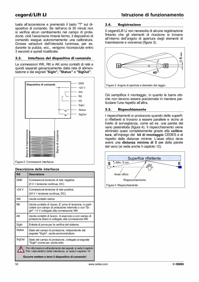
cegard/Lift LI Istruzione di funzionamento
52 www.cedes.com © CEDES
tuata all’accensione e premendo il tasto "T" sul di-spositivo di comando. Se nell’arco di 30 minuti non si verifica alcun cambiamento nel campo di prote-zione, cioè l’ascensore rimane fermo, il dispositivo di comando esegue autonomamente una calibratura. Grosse variazioni dell’intensità luminosa, per es. durante la pulizia, ecc., vengono riconosciute entro 3 secondi e quindi ricalibrate.
3.3. Interfacce del dispositivo di comando
Le connessioni WK, RK e AK sono contatti di relè e quindi separati galvanicamente dalla rete di alimen-tazione e dai segnali "SigIn", "Status" e "SigOut".
Bar
ra d
i tra
smis
sion
e
Bar
ra d
i ric
ezio
ne
Dispositivo di comando GND
+24 V
WKRK
AK
SigIn
Status
SigOut
Figura 2: Connessioni interfacce Descrizione delle interfacce Rif. Descrizione
GND Connessione tensione di rete negativa (0 V = tensione continua, DC)
+24 V Connessione tensione di rete positiva (24 V = tensione continua, DC)
WK Uscita contatto radice
RK Uscita contatto di riposo. E’ privo di tensione, in parti-colare con campo di protezione interrotto o con "Si-gIn" = 0 V collegato alla connessione WK
AK Uscita contatto di lavoro. In esercizio e con campo di protezione libero è collegato alla connessione WK
SigIn Entrata di prova per la verifica del sistema
Status Stato del campo di protezione, indipendente dal segnale "SigIn", uscita semiconduttore
SigOut Stato del campo di protezione, collegato al segnale "SigIn" (come per uscita relè)
Per informazioni sull’andamento dei segnali, si veda il capitolo 5 Per i dati elettrici delle interfacce, si veda il capitolo 10
Occorre mettere a terra il dispositivo di comando!
3.4. Registrazione
Il cegard/Lift LI non necessita di alcuna registrazione fintanto che gli elementi di ricezione si trovano all’interno dell’angolo di apertura degli elementi di trasmissione e viceversa (figura 3).
40°
5 m
m
S E
Figura 3: Angolo di apertura e diametro del raggio
Ciò semplifica il montaggio, in quanto le barre otti-che non devono essere posizionate in maniera par-ticolare l’una rispetto all’altra.
3.5. Rispecchiamento
I rispecchiamenti si producono quando delle superfi-ci riflettenti si trovano a essere parallele e vicino al livello di sorveglianza, come ad es. una parete del vano piastrellata (figura 4). Il rispecchiamento viene eliminato quasi completamente grazie alla calibra-tura, all’impiego del kit di montaggio CEDES e al rispetto delle distanze minime. L’asse ottico deve avere una distanza minima di 5 cm dalla parete del vano (si veda anche il capitolo 12).
Rispecchiamento
S E
Asse ottico
Superfice riflettenteMin. 5 cm
Figura 4: Rispecchiamento

Istruzione di funzionamento cegard/Lift LI
© CEDES www.cedes.com 53
4. Montaggio
4.1. Montaggio barre ottiche
Durante il montaggio delle barre ottiche occorre assicurarsi che:
la barra di trasmissione non venga montata ruotata di 180° rispetto a quella di ricezione. In pratica, i cavi di collegamento delle barre otti-che devono essere fatti passare verso l’alto (figura 5).
Tras
met
titor
e
Rice
vito
re
Tras
met
titor
e
Ric
evito
re
Errato
Corretto
Figura 5: Posizionamento trasmettitore / ricevitore
le barre ottiche si trovino a una distanza mi-nima di 5 cm dalla parete del vano. nessuna forza di trazione agisca sui cavi di
collegamento e che questi non siano schiac-ciati che i cavi di collegamento siano ben fissati e
tirati. Non devono essere soggetti a movimen-ti continui o sfregamenti. si prevengano accumuli di sporco o graffi. le barre ottiche siano ben tese mediante le viti
in dotazione. In caso di necessità, occorre stringere le viti con mezzi tradizionali affinché non si allentino. nell’eventualità di impiego di più barriere lumi-
nose una vicino all’altra, la luce di emissione non giunga al ricevitore di un altro sistema. In alcune circostanze è possibile che le barriere luminose si influenzino a vicenda. Pertanto negli ascensori dotati di porta-montacarichi, le barre di trasmissione e ricezione di entrambi gli accessi devono essere posizionate in mo-do alternato (figura 6).
Le barre ottiche sono dotate di pezzi di nastro bia-desivo, che possono essere d’aiuto nel montaggio e come misura antirumore sia in caso di montaggio su parete di fondo che montaggio non incassato. Per il montaggio consigliamo l’apposito kit e le maschere per foratura CEDES, che semplificano notevolmente l’installazione delle barre ottiche e aiutano a preveni-re i rispecchiamenti.
Ric
evito
re
Tras
met
titor
e
Ric
evito
re
Tras
met
titor
e
Ric
evito
re
Tras
met
titor
e
Tras
met
titor
e
Rice
vito
re
Ric
evito
re
Tras
met
titor
e
Ric
evito
re
Tras
met
titor
e
Figura 6: Posizionamento di più barriere luminose
4.2. Montaggio dispositivo di comando
Il dispositivo di comando viene fissato alla cabina nella posizione desiderata mediante viti. Accertarsi che:
durante il montaggio il carter del dispositivo di comando sia collegato elettricamente alla ca-bina (collegamento a terra). evitare per quanto possibile vibrazioni, assi-
curando un montaggio stabile. le barre ottiche e le spine di connessione al
dispositivo di comando non vengano attacca-te e staccate sotto tensione. Il dispositivo po-trebbe essere risultarne danneggiato.
4.3. Kit di montaggio versione "parete di fondo"
In questa versione le barre ottiche vengono montate dietro la cabina. I fori nella parete della cabina ven-gono praticati con la punta da trapano e con la ma-schera di foratura in dotazione. La maschera di fora-tura serve poi come pannello di sostegno per la copertura trasparente per infrarossi. Il fissaggio delle barre ottiche avviene allo stesso modo attraverso la parete della cabina dall’interno della stessa verso il suo esterno.
4.4. Kit di montaggio versione "senza in-casso"
Il pannello protettivo è in acciaio inossidabile V2A verniciato in giallo e nero con tutti i componenti di montaggio necessari.

cegard/Lift LI Istruzione di funzionamento
54 www.cedes.com © CEDES
5. Andamento dei segnali e norme di cablaggio
Cegard/Lift LI è paragonabile nella costruzione a una fotocellula testabile. Mediante l’applicazione di un segnale di prova si attiva un test e l’uscita si di-seccita. Durante i test il sistema esegue un’auto-verifica. Se il test ha successo, il segnale di prova si resetta lasciando nuovamente libera l’uscita (figura 7).
Campo di protezione
Test
Relais
Sig Out
Status
sgombrointerrotto
t1
t2
t3
t4
t6
t6
t5
t5
in ms min. typ. max.
t1 8 24 45
t2 3 20 40
t3 7 45 80
t4 3 40 72
t5 15 55 105
t6 10 50 100
Figura 7: Andamento dei segnali
Commenti all’illustrazione "Andamento dei segnali" Campo di protezione Area di sorveglianza della barriera luminosa
Segnale di prova
Deve giungere dal comando dell’ ascensore e viene inviato a SigIn
Relè Comportamento della bobina del relè Sig Out Uscita semiconduttore
Status Uscita semiconduttore, indipendente da SigIn quest’uscita indica sempre lo stato del campo di protezione
Importante avvertenza: Mediante un apposito comando di sicurezza, occor-re che questa procedura sia effettuata e verificata prima di ogni corsa. In caso di procedura scorretta la corsa non deve essere consentita. Occorre accer-tarsi che la funzione di controllo di cui sopra sia
anche sicura da difetti, cioè che un difetto non pro-duca uno stato insicuro
Importante avvertenza: Per un corretto funzionamento in esercizio, SigIn deve avere costantemente 24 VDC.
Nota: Nel cablaggio del comando di blocco nonché nel collegamento di interruttori di potenza esterni, occor-re rispettare la schermatura adatta (componenti spegniarco), si veda anche cap 8.1 e cap. 8.2.
6. Messa in funzione
Dopo il montaggio le barre ottiche vengono collega-te al dispositivo di comando. La spina contrassegna-ta in blu (barra di ricezione) viene collegata alla pre-sa "Receiver", la spina contrassegnata in bianco (barra di trasmissione) alla presa "Transmitter". Le spine sono codificate e non possono essere scam-biate o inserite in modo errato. Accertarsi che i due nottolini di arresto della spina siano posizionati cor-rettamente. Premendo i due nottolini di arresto è possibile rimuovere la spina.
Infine vengono collegati gli allacciamenti del morset-to ad innesto (osservare l’occupazione del collega-mento).
Il dispositivo di comando dispone di un micropro-cessore, che dopo l’accensione verifica l’intero si-stema di barriera luminosa. Si svolge quindi la se-guente procedura:
LED Alarm R
LED Alarm T
t1
t2= ca. 2 s (calibratura )t3= pronto
t1= ca. 10 s (auto-test )
accesso
accesso
spento
spento
t2 t3
Figura 8: Stato del LED R & T dopo il Power Up del dispositivo di comando
Dopo l’accensione della corrente, il LED "Power" sul dispositivo di comando deve illuminarsi subito e rima-nere acceso. Sul dispositivo di comando lampeggia-no i LED "AlarmR" e "AlarmT" per segnalare l’auto-test in corso per ca. 10 secondi alternativamente con 1 Hz (figura 8). Successivamente si accendono en-trambi i LED e restano accesi per ca. 2 secondi. In quest'intervallo di tempo la barriera luminosa si cali-bra. Dopodiché i due LED "AlarmR" e "AlarmT" si spengono.
Durante lo svolgimento di questa procedura il campo di protezione deve essere sgombro. Il sistema è ora pronto all’uso senza effettuare ulteriori regolazioni!

Istruzione di funzionamento cegard/Lift LI
© CEDES www.cedes.com 55
7. Elementi di comando e indicatori
7.1. Interruttore a levetta
Pow
erSi
gOut
SigI
nA
larm
RA
larm
T
Receiver TransmitterT 0
7.2. LED-Anzeigen
Power Interno 5 V ok
SigOut Relè acceso (breve lampeggio = auto-test ok)
SigIn Stato di ingresso del segnale SigIn
on = high (durante l’esercizio deve essere su "high")
AlarmR LED diagnostico barra ricezione
AlarmT LED diagnostico barra trasmissione
Pow
er
SigO
ut
SigI
n A
larm
R
Ala
rm T
Descrizione
La barriera luminosa esegue una calibratura. In tal modo determina l’intensità di trasmissione necessaria a far sì che i l ricevitore possa ricevere il segnale. Questa procedura dura tra uno e cinque secondi
Il lampeggio alternato di AlarmR e AlarmT segnala l’avvio dell’auto-test (ca. 10 secondi)
Pos ’T’ (Tasto)
Avvia la procedura di calibratura. I LED "AlarmT" e "AlarmR" si accendono contemporaneamente e restano accesi per tutta la durata della calibratura. In quest'intervallo di tempo il campo di protezione deve essere sgombro. Se si riconoscono elementi difettosi o coperti, il numero degli stessi viene indicato dal lampeg-gio del LED AlarmR per il ricevitore e del LED AlarmT per gli ele-menti di trasmissione. Esempio: se il LED AlarmT lampeggia tre volte dopo la calibratura, ci sono tre elementi di trasmissione coper-ti o difettosi.
Pos ’0’
Esercizio normale. Il cicalino non suona.
Pos Il cicalino suona in caso di interruzione del campo di protezione
Simboli LED
LED off
LED on
LED irrelevant (on / off)
LED blinking

cegard/Lift LI Istruzione di funzionamento
56 www.cedes.com © CEDES
8. Risoluzione dei problemi
Problema
Pow
er
SigO
ut
SigI
n A
larm
R
Ala
rm T
Cosa devo verificare? Altre indicazioni
Non funziona (A) . • E’ corretta la polarità della tensione di alimentazione? • Il fusibile interno è a posto? • La tensione di alimentazione è tra 17 ... 30 VDC?
Non funziona (B) . • E’ libero il passaggio della luce tra trasmettitore e ricevitore? • I fori nella parete della cabina sono di diametro adeguato (mini-
mo 10 mm di diametro) e adatti ai sensori? • Le barre sono allacciate correttamente (sede corretta delle
spine)?
Non funziona (C) La barriera luminosa emette un fischio in caso di interruzione (cicalino attivo/acceso) ma il relè non si attiva
. Il segnale SigIn è cablato correttamente? Affinché il relè possa chiudersi, SigIn deve essere sotto tensione (20 ... 30 VDC).
Si veda il cap.5
Non funziona (D) Si veda 'Non funziona (B)' Non funziona (E) Si veda 'Non funziona (B)'
Non funziona (F) La barriera luminosa ripete la procedura di avvio senza ragione apparente
• E’ presente un’altra fonte di infrarossi nei pressi della barriera luminosa (per es. una fotocellula)? Occorre rimuoverla.
• La tensione di rete indica interruzioni di tensione? Fissare il condensatore elettrolitico da min. 470 uF / 50 V tra "GND" e "+24 V"!
Attivazione sporadica senza oggetto nella medesima posi-zione
• Un oggetto è troppo vicino al campo di protezione (cavi pensili, ...) • Superata la portata di esercizio • Dopo una chiamata della cabina il motore di arresto funziona,
ma la barriera luminosa antinfortunistica non scatta, nonostante nel campo di protezione non vi sia nulla. Disturbi elettromagne-tici!
cap. 8.1 cap. 8.2
Attivazione sporadica senza oggetto in diverse posizioni
• E’ presente un’altra fonte di infrarossi nei pressi della barriera luminosa (per es. una fotocellula)? Occorre rimuoverla.
• fori praticati sono di diametro adeguato (minimo10 mm)? • Il carter del dispositivo di comando è collegato a terra? • Il collegamento "GND" è collegato al centro neutro di terra? • Un oggetto è troppo vicino al campo di protezione (cavi pensili,
...) • Le uscite SigOut o Alarm sono cablate? Le linee sono allacciate
il più vicino possibile? Nel caso di collegamenti lunghi, entrambi questi segnali devono essere disaccoppiati mediante un relè.
cap. 8.1 cap. 8.2
Durante la corsa l’ascensore va in arresto di emergenza, senza che la barriera luminosa sia stata interrotta
• Verificare la messa a terra del dispositivo di comando • Applicare la variante di schermatura 1 (se necessario variante di
schermatura 2)
cap 4.2
cap 8.1 (8.2)

Istruzione di funzionamento cegard/Lift LI
© CEDES www.cedes.com 57
8.1. Variante di schermatura 1
24 VDC +-
cabina
unità di controllo
cegard/Lift LI
elementi ottici
cegard/Lift LI
+-
contatto assicurato mediante vite
Collegare un condensatore bipolare (min. 10uF/ 50V, poliestere o poli-carbonato) tra il polo negativo dell'ali-mentazione e il contenitore dell'unità dicontrollo cegard/Lift. Utilizzare un cavo flessibile il più corto possibile, con un diametro esterno di min. 2.5 mm, allo scopo di eliminare gli impulsi brevi.
cavo sospeso(vano)
contatto assicurato mediante cavo
sala delle macchine
Figura 9: Variante di schermatura 1

cegard/Lift LI Istruzione di funzionamento
58 www.cedes.com © CEDES
8.2. Variante di schermatura 2
Sintomo: l’azionamento o il rilascio del blocco possono recare disturbo alla barriera luminosa antinfortunistica, se l’attivazione del blocco non è schermata. Tale disturbo si manifesta nel fatto che l’ascensore non può più es-sere spostato dal piano, fino a quando non viene effettuato un nuovo PowerUp della barriera luminosa antinfor-tunistica. Schermatura: la seguente variante ha dato buoni risultati in diversi casi con motori di arresto trifasici. <
24 VDC+-
sala delle macchine
cabina
unità di controllo
cegard/Lift LI
elementi ottici
Cegard/Lift LI
cavo sospeso (vano)
+-
contatto assicurato mediante vite
Connettere il polo comune di RC-filtro adun cavo supplementare o al neutro della luce di cabina per deviare le inter-ferenze eletromagnetiche del blocco porta su un altro cavo.
M
cavo neutro della lucedi cabina
RC-filtro
PE
motore per chiudere
la porta
il telaio metallico èconnesso al PE
da collegarecon il cavo
collegamentoda rimuovere
cavo PE supplementare
PE2
N
contatto assicurato mediante cavo
N
L1
L2
L3
Figura 10: Variante di schermatura 2

Istruzione di funzionamento cegard/Lift LI
© CEDES www.cedes.com 59
9. Norme
E’ possibile garantire un fun-zionamento sicuro e durevole soltanto se si rispettano i punti descritti in seguito nonché l’allacciamento e i valori limiti
forniti in questo manuale d’uso da parte dell’impresa di montaggio, dei punti di assistenza e da parte dell’utente. In caso di mancata osservanza, l’esercizio del sistema non è consentito.
9.1. Leggi e norme
L’impresa di montaggio, i punti di assistenza e l’utente devono osservare le leggi locali e nazionali, nonché le disposizioni del costruttore dell’ascensore, affinché cegard/Lift LI espleti e ga-rantisca nel tempo la sua funzione di sicurezza per gli utenti.
9.2. Qualifica del personale esperto
Montaggio, messa in funzione e manutenzione di cegard/Lift LI devono essere effettuati esclusiva-mente da personale qualificato, che possa dimostra-re un’adeguata formazione nel campo delle tecniche di sicurezza negli impianti ascensoristici. Il dispositi-vo di comando deve essere installato in modo tale che persone non autorizzate non abbiano alcuna possibilità di modificarne il cablaggio. Questo si ottiene effettuando il montaggio sul tetto della cabi-na. Prima di mettere in funzione l’ascensore, occorre verificare se la barriera luminosa risponde nell’intero campo da sorvegliare. E’ possibile a tal fine attivare il cicalino montato nell’unità di innesto, il quale emet-te un segnale acustico in caso di interruzione di ogni raggio luminoso. Come corpo di verifica è possibile utilizzare per es. un tubo in plastica nero con un diametro che corri-sponda al potere risolvente delle barre ottiche e che sia di lunghezza minima di 200 mm.
9.3. Verifiche periodiche
Occorre verificare il corretto funzionamento di ce-gard/Lift LI ad ogni manutenzione dell’ascensore. Occorre quindi controllare, se la barriera luminosa risponde nell’intera zona di sorveglianza mediante il corpo di verifica corrispondente (per es. con l’aiuto del cicalino montato).
9.4. Rispecchiamento
Anche una calibratura molto precisa, come quella che ha luogo nel dispositivo di comando, non sem-pre può impedire qualsiasi rispecchiamento. Pareti del vano estremamente riflettenti, che corrono paral-lele alla superficie di sorveglianza (piastrellate o rivestite da pannelli metallici) o anche brevi distanze
tra barre di trasmissione e ricezione, possono cau-sare rispecchiamenti. Se non è possibile un’interruzione, occorre ridurre la riflessione me-diante provvedimenti adeguati. Questo può per es. succedere mediante il kit di montaggio su parete di fondo (4.3), mediante una vernice nero opaco, me-diante sabbiatura o interposizione di un diaframma o aumento della distanza dalla parete del vano.
9.5. Pulizia delle barre ottiche
cegard/Lift LI è un dispositivo ottico. Pertanto le barre ottiche devono essere pulite esclusivamente con un panno morbido e in caso di sporco resistente lavate con acqua saponata. Non utilizzare in nessun caso solventi. Questi potrebbero distruggere le barre ottiche o causare perdite di portata.
9.6. Cablaggio
Il cablaggio di sicurezza del cegard/Lift LI deve sod-disfare i seguenti requisiti:
deve impedire la corsa oppure arrestare il motore, se viene rilevata un’intrusione non ammessa nella zona di protezione da parte della barriera luminosa (apertura del circuito di sicurezza). il sistema deve essere cavallottato ai fini del ro-
daggio e della registrazione. non è necessario cancellare i comandi corsa
memorizzati durante la risposta del dispositi-vo di protezione. se il dispositivo di protezione ha interrotto una
corsa, dopo lo sgombro della zona di prote-zione è possibile ottenere un‘ulteriore corsa soltanto mediante un nuovo ordine di corsa proveniente dall’interno della cabina. un danno al dispositivo di protezione causato
da un guasto ai sensi di TRA 262.12, SIA 370/10 o altre norme nazionali deve essere ri-levato automaticamente prima di ogni corsa escluso per la registrazione e per la restitu-zione. In presenza di un guasto non è con-sentito iniziare la corsa. Il test della barriera luminosa lo verifica prima di ogni corsa.
Importante avvertenza:
Il relè di uscita non deve per nessuna ragione esse-re attivato direttamente nel circuito di sicurezza dell’ascensore (morsetti WK, RK e AK) o essere caricato con tensione di rete (osservare anche le disposizioni di cui al cap.11).

cegard/Lift LI Istruzione di funzionamento
60 www.cedes.com © CEDES
10. Dismissione, riparazione e smaltimento
10.1. Dismissione
Il cegard/Lift LI può essere dismesso soltanto nel caso in cui venga installato un dispositivo antinfortu-nistico equivalente o superiore, per es. il montaggio di una porta di cabina interna. In tal caso occorre smontare completamente i kit di montaggio, le barre ottiche, il dispositivo di comando e le istruzioni per i passeggeri.
10.2. Riparazione
Qualsiasi riparazione viene effettuata esclusivamen-te dal servizio assistenza CEDES o da personale qualificato espressamente autorizzato da CEDES.
Importante avvertenza: Qualsiasi altra riparazione effettuata in altro modo può compromettere la sicurezza comportando dei pericoli per gli utenti dell’ascensore
10.3. Smaltimento
Vi preghiamo di conferire il cartone dell’imballo ai circuiti di riciclaggio. Quantitativi di imballaggio di una certa entità possono anche essere restituiti alle filiali CEDES. La filiale o la rappresentante CEDES ritira gli imbal-laggi e l’apparecchio usato per lo smontaggio e ne riconferisce i componenti al circuito di valorizzazione dei materiali.

Istruzione di funzionamento cegard/Lift LI
© CEDES www.cedes.com 61
11. Dati tecnici
Dati elettrici e ottici
Tensione di alimentazione 17 ... 30 VDC
Corrente assorbita < 150 mA
Fusibile protezione tensione di alimentazione
500 mAF
Uscita relè
Contatto relè scambiatore relè 24 V / 1 A, non utilizza-re per attivare la tensione di rete né direttamente nel circuito di sicurezza dell’ascensore!
2 uscite semiconduttori ("Status" e "SigOut")
PNP 100 mA, anticortocir-cuito
Entrata "SigIn" 0 ... 3 VDC per "Low", 10 - 30 VDC per “High"
Tempo di reazione uscita < 80 ms, tip. 50 ms
Portata di esercizio Da 0.7 a 4 m risp. da 4 a 8 m (secondo la versione)
Campo di protezione Vedi 13.1.
Numero raggi luminosi 46 (con 16 coppie di senso-ri)
Angolo di apertura trasmettitore e ricevitore
± 20°
Riserva luminosa dopo la calibratu-ra
ca. 100 %
Luce estranea massima ammessa, sistema 0,7 ... 4,0 m
50'000 Lux
Luce estranea massima ammessa, sistema 4,0 ... 8,0 m
5'000 Lux
Altri dati
Sezione barra ottica (B x T) 14 x 17 mm
Lunghezza barre ottiche 1'730 mm
Misure unità di comando (B x T x H)
203 x 123 x 44 mm
Tipo di dispositivo Barriera luminosa antinfor-tunistica testabile tipo 2 (EN 954-1)
Allacciamenti Morsetti di innesto-molla di trazione a gabbia, 8-poli, 1,5 mm²
Tipo di protezione dispositivo di comando / barre ottiche
IP20 / IP65
Range di temperatura: esercizio / magazzino
-20°...+65°C
Clima di funzionamento IEC 68-2-1/2
Sollecitazione meccanica di impie-go (vibrazione e shock)
IEC 68-2-6
Dimensioni barre ottiche Si veda 13.1.
Dimensioni dispositivo di comando Si veda 13.2.
Resistenza ai disturbi e emissione perturbatrice EMV (compatibilità elettromagnetica)
Conforme CE (si veda il capitolo 14 )
Scarica elettrostatica -scarica atmosferica
-scarica di contatto
IEC 61000-2 15 kV, Coefficiente di finezza 4 6 kV, Coefficiente di finezza 3
Irradiazione AF: campi elettroma-gnetici
IEC 61000-3, 27 - 1000 MHz, 10 V/m, Coefficiente di finezza 3
Resistenza ai disturbi su Walkie-Talkie
BS 5588, Part 5:91, App. C
Transienti elettrici veloci IEC 61000-4: 4 kV, Coefficiente di finezza 4
Sovratensione transiente IEC 61000-5: Coefficiente di finezza 3
Interruzioni di rete IEC 61000-4-11, < 10 ms, Coefficiente di finezza 1
Tensione radiodisturbo EN 55011 Gruppo 1, classe B
Radiazione radiodisturbo EN 55011: Gruppo 1, classe B
Radiazione radiodisturbo VDE 0871, classe B
Installazione
Occorre rispettare le seguenti norme:
-Proposta del DAA del 22.11.1990 (Germania)
-Direttive di cui a EN 81 (Europa)
-Direttive di cui al TRA 101, sezione 8. (Germania)
-Direttive di cui al TRA 200 (Germania)
-Direttive di cui al SIA 370 / 10 (Svizzera)
-Leggi e norme nazionali (nei paesi non menzionati)
Dichiarazione di conformità Si veda A.1.
Certificato TÜV Si veda A.2 o homepage CEDES

cegard/Lift LI Istruzione di funzionamento
62 www.cedes.com © CEDES
12. Informazioni d’ordine
12.1. Sistemi completi
CEDES Numero articolo
Descrizione
100 891 cegard/Lift LI completo per una cabina con accesso 0,7 ... 4,0 m. Barre ottiche a 16 elementi, altezza di sorveglianza 1630 mm Lunghezza cavi di collegamento: barra di ricezione 6 m, barra di trasmissione 6 m
100 892 cegard/Lift LI completo per una cabina con accesso 4.0 ... 8.0 m. Barre ottiche a 16 elementi, altezza di sorveglianza 1630 mm Lunghezza cavi di collegamento: barra di ricezione 10 m, barra di trasmissione 6 m
12.2. Pezzi di ricambio / pezzi singoli
CEDES Numero articolo
Descrizione
100 938 Dispositivo di comando
102 005 Dispositivo di comando per barre ottiche a 24 elementi
101 249 Barra di trasmissione. 16 elementi, altezza di sorveglianza 1630 mm
101 248 Barra di ricezione 0,7 ... 4,0 m. 16 elementi, altezza di sorveglianza 1630 mm
101 281 Barra di ricezione 4,0 ... 8,0 m. 16 elementi, altezza di sorveglianza 1630 mm
101 072 Coppia di barre portata 0,7 ... 4,0 m. 16 elementi, altezza di sorveglianza 1630 mm
101 073 Coppia di barre portata 4,0 ... 8,0 m. 16 elementi, altezza di sorveglianza 1630 mm
102 809 Coppia di barre portata 0,7 ... 4,0 m. 24 elementi, altezza di sorveglianza 1908 mm
102 812 Coppia di barre portata 0.7 ... 4.0 m. 24 elementi, altezza di sorveglianza 2012 mm
101 090 Manuale d’uso in 4 lingue (T / F / I / I)
101 250 Finestra IR per set di montaggio parete di fondo
12.3. Accessori
CEDES Numero articolo
Descrizione
100 847 Kit montaggio per il montaggio su parete di fondo, compresi maschera di foratura e punta trapano, (acciaio inox, verniciatura giallo-nero)
100 848 Kit montaggio e pannello protettivo per i l montaggio non incassato di un accesso, compresi maschera di foratura e punta trapa-no, (acciaio inox, verniciatura giallo-nero)
101 291 Maschera di foratura, se non si desidera utilizzare il kit 100 847
100 098 Contattore a relè per il funzionamento di una porta automatica o per l’indicatore di controllo di carico in caso di ascensori dotati di porta-montacarichi. Tensione di rete minima del sistema 22 VDC.
100 849 Dispositivo d’allarme per montaggio non incassato, compreso 4 m di cavo di collega-mento per tono continuo o intermittente
104 075 Fotocellula a forcella GLS 126 per ritardo di cavallottamento, 5 m di cavo, NC
104 073 Fotocellula a forcella GLS 126 per ritardo di cavallottamento, 5 m di cavo, NO
101 243 Targhetta istruzioni 4 lingue (tasto di reset)
Altri sistemi e accessori sono disponibili su richiesta presso il vostro partner o la vostra rappresentante CEDES.
12.4. Coppie di barre su misura
CEDES Numero articolo
Descrizione
101 471 Coppia di barre a 16 elementi Lunghezza delle barre e altezza di sorve-glianza su richiesta
101 472 Coppia di barre a 24 elementi Lunghezza delle barre e altezza di sorve-glianza su richiesta
Se lo desiderate, è possibile ordinare le barre pos-sono anche in IP67.

Istruzione di funzionamento cegard/Lift LI
© CEDES www.cedes.com 63
13. Disegni quotati
13.1. Dimensioni barre ottiche
700 ... 4000
730*
725*
1730
235*
1630
1505
1380
1255
1130
1005
880
755
630
505
380
255
17012070200
Trasmettitore(bianco)
Ricevitore(blu)
•
•
••
•
•
17
14M4
Lunghezza cavo 6 m No. d'articolo:101 072 101 073 Comprese nel sistema: 100 891 e 100 892
Sezione trasversale dell'elemento ottico
Facoltativo: Foro di passaggio
* = Fori di montaggio Ø 4.5 mm
Facoltativo: 70 raggi Campo di azione 4 ... 8 m
Altre configurazioni con 24oppure 36 elementi
(dimensioni in mm)

cegard/Lift LI Istruzione di funzionamento
64 www.cedes.com © CEDES
13.2. Dimensioni dispositivo di comando
(dimensioni in mm)
Prese saldate M3x4,5 / 5x8 o prese incassate M3x8
6 pz. forature
120
16
98.8
±0.2
80±0
.2
25
3.8
50
17.8±0.2 6 15
200
170.2±0.2 188±0.2
130±0.2
160±0.2 20
15
15 15
5
Ø10
5±0,
2

Appendix / Anhang / Appendice cegard/Lift LI
© CEDES www.cedes.com 65
A. Certificates / Zertifikate / Certificat / Certificato
A.1. Declaration of conformity / Konformitätserklärung / Déclaration de conformità / -Dichiarazione di conformità

cegard/Lift LI Appendix / Anhang / Appendice
66 www.cedes.com © CEDES
A.2. TÜV-Certificate / TÜV-Zertifikat / TÜV-Certificat / TÜV-Certificato

cegard/Lift LI
© CEDES www.cedes.com 67