Installation and operation manual - download.vimar.com and operation manual Art. 69AM/T Switching...
16
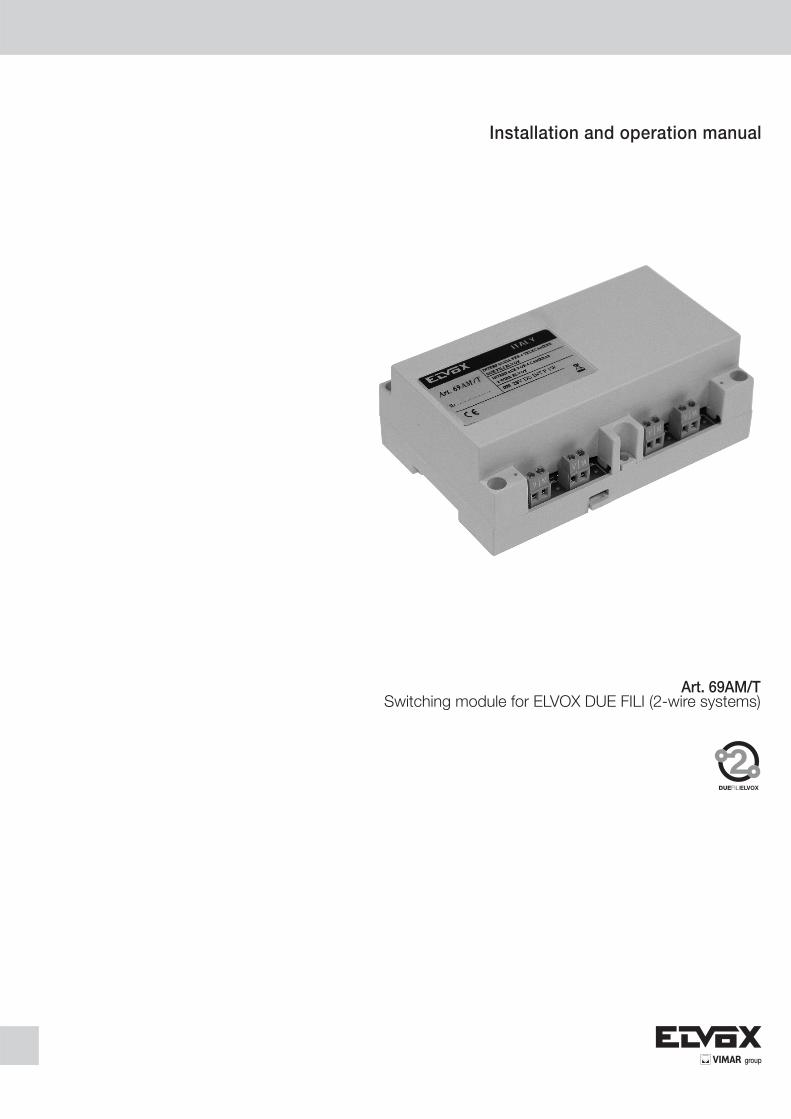
Installation and operation manual Art. 69AM/T Switching module for ELVOX DUE FILI (2-wire systems)
Transcript of Installation and operation manual - download.vimar.com and operation manual Art. 69AM/T Switching...
Installation and operation manual
Art. 69AM/TSwitching module for ELVOX DUE FILI (2-wire systems)
2 EN
CONTENTS PAGE- WARNINGS FOR THE INSTALLER 21. GENERAL INFORMATION 32. ELECTRICAL INSTALLATION 43. HARDWARE CONFIGURATION 43.1. BUS TERMINATION 43.2. VIDEO TERMINATION 43.3. ASSIGNING IDENTIFICATION 44. SOFTWARE CONFIGURATIONS 54.1 MESSAGE LANGUAGE 64.2. SWITCHING MODULE ID 64.3. CONVERSATION TIME 64.4. SELF-START TIME 74.5. FUNCTION 1 TIME 74.6. FUNCTION 2 TIME 84.7. F1 COMMON 84.8. F2 COMMON 84.9. NUMBER OF CAMERAS 94.10. SELF-START SEQUENCE 94.11. CALL BUTTON CAMERA 104.12. SPEECH UNIT ID 114.13. VIMAR 114.14. TOTAL RESET 115. OPERATION 12- WIRING DIAGRAMS 13
EN 3
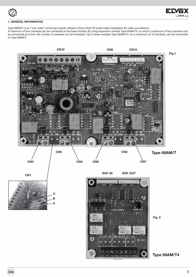
1. GENERAL INFORMATION
Type 69AM/T is an “only video” switching module utilised in Elvox DUE Fili audio/video installation for video surveillance. A maximum of four cameras can be connected to the base module. By using expansion module Type 69AM/T4, to which a maximum of four cameras canbe connected at a time, the number of cameras can be increased. Up to three modules Type 69AM/T4, for a maximum of 16 cameras, can be connectedto Type 69AM/T.
Fig.1
Fig. 2
CN10 CN9 CN15
CN5 CN2
CN3 CN4 CN6 CN7
EXP. IN EXP. OUT
Type 69AM/T
Type 69AM/T4
C
B
A
CN1

EN4
Fig. 3
Art. 69AM/T Art. 69AM/T4 Art. 69AM/T4 Art. 69AM/T4
Connector CN15 of the 69AM/T module must be connected to EXP. IN of the first 69AM/T4 module. EXP.OUT of 69AM/T4 must be connected to EXP.INof the following module, and so forth. The cameras are connected by means of a coaxial cable to V1-M1, V2-M2, and so forth.
Max. 3modulesType 69AM/T4
The 69AM/T switching module cannot be used as a Master entrance panel.
2. ELECTRICAL INSTALLATIONThe interface is connected to the system by means of the CN10 terminal block on the top left side.
ADDITIONAL MODULES MAXIMUM NUMBER OF CAMERAS
0 4
1 8
2 12
3 16
3. HARDWARE CONFIGURATIONHereinafter reference is made to CN10 positioned at the top left.
3.1. BUS TERMINATIONConnector CN1 is located on the top left side below CN10. A jumper in one of the three possible positions (A, B, C) makes it possible to terminate thebus correctly with reference to the video signal. Identify the condition that provides the best viewing compromise.
3.2. VIDEO TERMINATION When jumpers CN3, CN4, CN6 and CN7 are closed they interpose a 75 Ohm termination for each of the four possible video signals. Needless to add,the terminations are independent (already set by default).
3.3. ID ASSIGNMENTThe identifier is assigned by means of software programming.The switching module can be identified as an entrance panel or as a device. To identify the switching module as an entrance panel the parameter EN-TRANCE PANEL ID must be set to a number between 2 and 15. To identify the switching module as a device the parameter ENTRANCE PANEL ID mustbe set to 0 and then a value of between 1 and 200 must be assigned to the parameter DEVICE ID (see headings 4.2 and 4.3).
MARKING DESCRIPTION
+ E +I of an auxiliary power supply unit Type 6923, the negative pole must be connected to M
F2 Open-collector output, max 100 mA. Use +12 Vdc for the power supply
F1 Open-collector output, max 100 mA. Use +12 Vdc for the power supply
12 To be used for feeding loads on F1 and / or F2. Max 100 mA. Present only when at least one of the following is active: F1, F2,camera, data transmission
M Reference ground of +I, 12, +E
+ I Max. positive active output 100 mA (+12 Vdc when one camera is switched on).
B1, B2 Elvox Due Fili Bus
The maximum number of cameras according to the number of additional 69AM/T4 modules is specified in the table below:

5EN
The programmer keypad layout is as follows:
4. SOFTWARE CONFIGURATIONS Configurations can be carried out via programmer Type 950C connected to CN9 on the top right-hand side and accessible also from the exterior of thecover. Otherwise, interfaces Type 692I or 692I/U can be used together with the SaveProg PC complete software.Programming procedures concern the switching module to which the programmer is connected.The configurable parameters are:
PARAMETER DEFAULT NEXT ITEM PREVIOUS ITEM SUB ITEM
Language English (Local language)
ID as entrance panel 0 (Not Assigned)
ID as device 0 (Not Assigned)
Conversation time 120 s
Self-start time 10 s
FUNCTION 1 TIME 1 s
FUNCTION 2 TIME 1 s
F1 COMMON Blank 4 x or
F2 COMMON Blank 4 x or
Number of Cameras 1
Self-start sequence Blank 204 x or
Speech Unit Camera Blank 200 x or
Speech Unit ID Blank 4 x or
Audio powered (only 69AM) YES 16 x or
For EEPROM reset N.A.

EN6
The key has no function as the programmer is powered by the bus.For the same reason the auto-shutdown function is not available. The pro-
grammer keys and and enable selection of the item requiredfrom the main menu, from the following:
During the waiiting for an answer from the panel, the display shows:
After a few seconds, the programmer display shows the type and ver-sion of the software related to the panel:
When this disappears, the first item of the programming menu is displa-yed. The programming procedure terminates either when the timeout
elapses or when the key is pressed while the user is in any of theexternal menus listed below.
4.1 MESSAGE LANGUAGE
Programming can be in Italian local (default) or English. Other local lan-guages will be available for the respective markets.
To change language, press for local or for English.
To cancel, press . To confirm, press . Acceptance of the com-mand, as in all cases, is shown on the first line of the display:
The display now changes to:
Use the key to move to the previous item in the programmingmenu.
4.2. SWITCHING MODULE ID AS ENTRANCE PANEL
Press to move to the next item, which allows you to change the swit-ching module ID. To change the ID, enter number 0 or a number between2 and 15.
To cancel press . To confirm, press . After running a check toascertain that the system does not include any other entities at the timehaving the same address, the acceptance of the ID change is shown onthe top line of the display:
If the ID number is off range, the error is indicated on the top line of the di-splay:
Use the key to return to the previous item in the programming menu.
4.3 SWITCHING MODULE ID AS DEVICES
Pressing push-button you scroll to the next item through that you canchange the switching module identification code, but considered as inter-phone or video interphone. As default the ID is not assigned:
To change identification code, enter the digits as to form a number from 1to 200 in such a way it is not equal to an interphone or video interphoneidentification code (ID).
To cancel press . To confirm press push-button . After controllingthat in the installation, in that moment, there is not any other object withthe same address, the command acceptance is indicated in the first line ofdisplay:
If the Identification Code (ID) is out of limit, the first display line shows theincongruence:
With push-button you scroll to the next item of the programming menu
4.4. CONVERSATION TIME
Press to go to the next option, where you can edit the time duringwhich conversation with the switching module remains on the moni-tor/interphone. The current value is shown on display:
By entering digits the time can be changed in ten-second steps:
To cancel press . To confirm, press . As for all the other commands,acceptance of this command is shown on the first line of the display:
If the time entered is outside the admissible interval, i.e. over 2550 se-conds, the error is shown on the top line of the display:
Press to return to the previous item in the programming menu.
4.5. SELF-START TIME
Press to go to the next item in which the user can modify the timefor which the self-start function requested from the monitor or interphonelasts on the panel. The current value is shown on display:
On entry of digits, the time can be modified in intervals of seconds:
To cancel, press . To confirm, press . Acceptance of the com-mand, as in all cases, is shown on the first line of the display:
If the time is outside the admissible interval, i.e. over 255 seconds, thefirst line of the display shows the error:
Use the key to move to the previous item in the programming menu.

7EN
4.6. FUNCTION 1 TIME
Press o go to the next item in which the user can modify the timefor which output F1 is activated. The current value is shown on display:
On entry of digits, the time can be modified in intervals of seconds:
To cancel, press . To confirm, press . Acceptance of the com-mand, as in all cases, is shown on the first line of the display:
If the time is outside the admissible interval, i.e. over 255 seconds, thefirst line of the display shows the error:
Value 0 has the special meaning of activating output F1 for 0.5 seconds:
Use the key to move to the previous item in the programmingmenu.
4.7. FUNCTION 2 TIME
Press to go to the next item in which the user can modify the timefor which output F2 is activated. The current value is shown on display:
On entry of digits, the time can be modified in intervals of seconds:
To cancel, press . To confirm, press . Acceptance of the com-mand, as in all cases, is shown on the first line of the display:
If the time is outside the admissible interval, i.e. over 255 seconds, thefirst line of the display shows the error:
Value 0 has the special meaning of activating output F2 for 0.5 seconds:
Use the key to move to the previous item in the programmingmenu.
4.8. COMMON F1
Press to move to the next item in which the user can set for whichother F1 activations the current panel must activate its output. In prac-tice the F1 output of a panel can be activated not only on a direct com-mand, but also indirectly when the F1 of another panel (max. four) isactivated.There is no assignment by default:
Enter a number between 1 and 15, i.e. the panel ID (in this case the firstof four possible options) which must also activate its F1 function on thiscommand:
To cancel, press . To confirm, press . Acceptance of the command,as in all cases, is shown on the first line of the display:
If the ID is outside the admissible range, the first line of the display showsthe error:
To cancel the assignment, enter a single ‘0’ as ID:
Use keys and . to move from one index to another. From position
1, press to move to the next item in the programming menu.
Use the key to skip all intermediate phases and go to the previousitem in the programming menu.
4.9. COMMON F2
Press to move to the next item in which the user can set for whichother F2 activations the current panel must activate its output. In prac-tice the F1 output of a panel can be activated not only on a direct com-mand, but also indirectly when the F2 of another panel (max. four) isactivated. There is no assignment by default:
Enter a number between 1 and 15, i.e. the panel ID (in this case the first offour possible options) which must also activate its F2 function on this com-mand:
To cancel, press . To confirm, press . Acceptance of the command,as in all cases, is shown on the first line of the display:
If the ID is outside the admissible range, the first line of the display showsthe error:
To cancel the assignment, enter a single ‘0’ as ID:
Use keys and . to move from one index to another. From position
1, press to move to the next item in the programming menu.
Use the key to skip all intermediate phases and go to the previousitem in the programming menu.
4.10. NUMBER OF CAMERAS
By pressing the push-button you can scroll to the next item throughwhich it is possible to program the cameras for CCTV connected to thebase module or through the additional modules type 69AM/T4. The ca-mera number must be according to the number of additional modules in-stalled:
Therefore as default only the basic module is to be used. To change this
number you must start entering the digits, for example than :
EN8
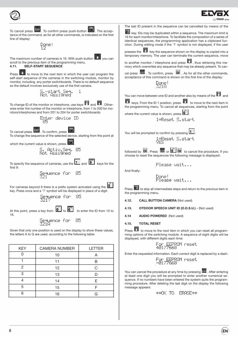
To cancel press . To confirm press push-button . The accep-tance of the command, as for all other commands, is indicated on the firstline of display:
The maximum number of cameras is 16. With push-button you canscroll to the previous item of the programming menu. 4.11. SELF-START SEQUENCE
Press to move to the next item in which the user can program theself-start sequence of the cameras in the switching module, monitor bymonitor, including any porter switchboards. There is no default sequenceso the default involves exclusively use of the first camera.
To change ID of the monitor or interphone, use keys and . Other-wise enter the number of the monitor or interphone, from 1 to 200 for mo-nitors/interphones and from 201 to 204 for porter switchboards:
To cancel press . To confirm, press .To change the sequence of the selected device, starting from the point at
which the current value is shown, press .
To specify the sequence of cameras, use the and keys for thefirst 9:
For cameras beyond 9 there is a prefix system activated using thekey. Press once and a '?' symbol will be displayed in place of a digit:
At this point, press a key from to to enter the ID from 10 to16.
Given that only one position is used on the display to show these values,the letters A to G are used, according to the following table:
The last ID present in the sequence can be cancelled by means of the
key. IDs may be duplicated within a sequence. The maximum limit is16 for each monitor/interphone. To facilitate the composition of a series ofidentical sequences, the programming application has a clipboard fun-ction. During editing mode if the '?' symbol is not displayed, if the user
presses the key the sequence shown on the display is copied into atemporary memory. The user can terminate the current sequence, move
to another monitor / interphone and press , thus retrieving this me-mory which overwrites any sequence that may be already present. To can-
cel press . To confirm, press . As for all the other commands,acceptance of this command is shown on the first line of the display:
You can move between one ID and another also by means of the and
keys. From the ID 1 position, press to move to the next item inthe programming menu. To cancel all sequences, starting from the point
where the current value is shown, press :
You will be prompted to confirm by pressing :
followed by . Press or to cancel the procedure. If youchoose to reset the sequences the following message is displayed:
And finally:
Press to skip all intermediate steps and return to the previous item inthe programming menu.
4.12. CALL BUTTON CAMERA (Not used)
4.13. OTDOOR SPEECH UNIT ID (O.D.S.U.) - (Not used)
4.14 AUDIO POWERED (Not used)
4.15. TOTAL RESET
Press to move to the next item in which you can reset all program-ming options of the switching module. A sequence of eight digits will bedisplayed, with different digits each time:
Enter the requested information. Each correct digit is replaced by a dash:
You can cancel the procedure at any time by pressing . After enteringat least one digit you will be prompted to enter another numerical se-quence. If no numbers have been entered the system quits the program-ming procedure. After deleting the last digit on the display the followingmessage appears:
KEY CAMERA NUMBER LETTER0 10 A1 11 B2 12 C3 13 D4 14 E5 15 F6 16 G

9EN
This message is always displayed in English. Press to delete all data,
or press again to cancel. After pressing the following messageis displayed for several seconds:
And lastly:
As before, this message is always displayed in English.
Press to restart the switching module programming procedure fromthe beginning.
5. OPERATION
First ensure that the electrical installation is correct and a unique ID hasbeen assigned to all devices in the system.Art. 69AM/T has no buttons and cannot therefore generate a call on itsown initiative. It can be used exclusively in self-start mode, either by in-serting it in a sequence of entrance panels and CCTV cameras or byusing a dedicated button. In the first case with switching module Art. 69AM/T set with entrancepanel ID, the self-start button can be pressed to switch from one en-trance panel to the next by continuing to press the self-start button of amonitor. Once the switching module “entrance panel” has been reached,you can scroll through the cameras associated with the switching mo-dule simply by pressing the LOCK button. In the second case, setting the switching module to device ID (choosingan available number), you can access the specific camera or camerasfrom the selected monitor directly. From an entrance panel you must seta button of the monitor as “intercom call” towards the switching modulein question and one of the parameters from C1 to C4 with the samenumber (switching module ID). The choice of the self-start sequence ofthe camera or cameras is executed by means of the “SELF-START SE-QUENCE” parameter.
The 69AM/T4 switching module has two outputs F1 and F2, which can beused as required. These outputs are of the open collector type, each ratedat 100 mA. The protection diode is already integrated internally on the+12V lines. Therefore, avoid using externally powered relays.As with the other panels, times are adjustable and can be set in commonwith other panels to obtained advanced functions. By subsequently pro-gramming the monitor/interphone function keys, special functions can beenabled such as access door opening, activation of a camera tilt mecha-nism etc.

EN10
BUS TERMINATION FOR ELVOX TWO-WIRE INSTALLATIONS
This note applies to all devices with ELVOX TWO-WIRE technology equipped with “BUS termination connector or dip-switch”, which is identified by thescreen-printed letters “ABC” and marked on the wiring diagrams with *. For correct adaptation of the line, make the setting according to the following rule:Maintain position “A” if the BUS enters and exits from the device;Move to position “B” (if Elvox cable) or to position “C” (if CAT5 twisted pair cable) if the BUS line terminates in the device itself.
“A” = NO TERMINATION “B” = TERMINATION 100 ohm “C” = TERMINATION 50 ohm
INSTALLATIONS WITH PASSIVE DISTRIBUTOR 692D (DIN rail version)ALWAYS use output 1 on distributor type 692D (the only one that has no termination jumper).For termination of type 692D: If outputs “OUT”, “2”, “3” or “4” are not used, KEEP the jumper on the “TOUT”, “T2”, “T3” or “T4” connector. The default“TOUT” connector is in the “100” position (Elvox cable), position it to “50” only if using a CAT5 twisted pair cable.
INSTALLATIONS WITH PASSIVE DISTRIBUTOR 692D(non-DIN rail version)For termination of type 692D (non-DIN rail version): If the “OUT” output is not used, KEEP the jumper on connector “A”. If the “OUT” output is used, RE-MOVE the jumper from connector “A”.
INSTALLATIONS WITH ACTIVE DISTRIBUTOR 692D/2.The termination jumper must be positioned on “B” (for Elvox cable) or on “C” (for CAT5 twisted pair cable) IF AND ONLY IF the BUS terminates at the de-vice itself. It must be left on “A” if effecting entry-exit using terminals 1-2 on 692D/2.
*
Conductor section
up to
10m
up to
50mup to
100m
up to
300m
Bus: 1, 2, B1, B2CABLE
Elvox (69MX) / Cat5 (69MX/5)
CABLE
Elvox (69MX) / Cat5 (69MX/5)
CABLE
Elvox (69MX) / Cat5 (69MX/5)
CABLE
Elvox (69MX) / Cat5 (69MX/5)
Ø 1,5 mm2 - - -
Others -, +U, +I, -L (#)
Ø 1 mm2 Ø 1 mm2 Ø 1,5 mm2 Ø 2,5 mm2
# Additional power supply units must be installed as close as possible to the device to which they are connected.
If it is connected to a CCTV camera type color in the device Art 69AM/T plug the jumper on the connector demoninato 75 Ohm.

11EN
22
11
2
2B1C
2D1D
2C
12
+-
11
2
1A2A
1B
CA MM +12V -L SR F1F2S-S+B2 B1 VLED X PAMEXT-
EXT+
PRI
B22
1B1
INOU
T
00
ADDR
ESS
12
BCA
+12V
F1F2
+EXT
GND
+IB2
B1EX
PANSIO
N MOD
ULEPR
OGRA
M
PRI +U
-+I
AB
CD
VV
VV
PRI +U
-+I
AB
CD
PRI +U
-+I
AB
CD
PRI +U
-+I
AB
CD
+T - V M
V2M1
V1M2
V4M3
V3M4
INOU
T
00
ADDR
ESS1
2
VV
VV
INOU
T
00
ADDR
ESS1
2
VV
VV
+T - V M
+T - V M
+T - V M
V2M1
V1M2
V4M3
V3M4
V2M1
V1M2
V4M3
V3M4
V2M1
V1M2
V4M3
V3M4
VIDEO ENTRANCE PANEL SYSTEM WITH INTERFACE TYPE 694M/T
Mai
ns
Cab
le r
iser
Co
nc
en
tra
tor
Art
. 692
C
Pow
er s
upp
lyA
rt. 6
922
Sel
ecto
r fo
r 4
cam
eras
Art
. 69A
M/T
Sel
ecto
r fo
r ca
mer
asA
rt. 6
9AM
/TS
elec
tor
for
cam
eras
Art
. 69A
M/T
Sel
ecto
r fo
r ca
mer
asA
rt. 6
9AM
/T
To o
ther
cam
eras
Pow
er s
upp
lyA
rt. 6
582
Mai
ns
Pow
er s
upp
lyA
rt. 6
582
Mai
ns
Pow
er s
upp
lyA
rt. 6
582
Mai
ns
Pow
er s
upp
lyA
rt. 6
582
Mai
ns
Cam
era
TVC
C 1
2Vd
cC
amer
aTV
CC
12V
dc
Cam
era
TVC
C 1
2Vd
cC
amer
aTV
CC
12V
dc
N° SI577C
able
Typ
e 73
2H
Cab
leTy
pe
732H
D-
“TW
O W
IRE
ELV
OX
” V
IDE
O E
NTR
AN
CE
PA
NE
L W
ITH
PU
SH
-BU
TTO
NS
L-
12V
ELE
CTR
IC L
OC
K
P-
LOC
K R
ELE
AS
E C
ON
TRO
L

EN12
+T-VM
B11 2 B2
PRI
EXT+EXT-
MPA
XVLED
B1B2
S+S-
F2F1
SR-L
+12V
M
M
CA
1B2A1A
21 1
-+
21
2C 1D 2D1C2B
211 22
DCBA+I- +U
PRI
B CA
+12VF1F2+EXT GND +I B2 B1EXPANSION MODULEPROGRAM
V2M1V1 M2 V4M3V3 M4
C
AB
+12CH
M
2
E-FP
E+
1
+I+U-
PRI
6PT3
VIDEO B
C
+-T4
A
12T1
6S5T2 4
1
E+
FPE-
2
M
CH+12
MV3
A
CB
4
12
23
1
13
BA
C
1 2 SIMPLE VIDEO ENTRANCE PANEL SYSTEM WITH INTER-FACE FOR CAMERA TYPE 69AM/T
Cable riser
Four cameras selector interface Art. 69AM/T
Power supplyArt. 6582
Mains
MonitorArt. 6621Art. 662CArt. 6721Art. 6611Art. 661CArt. 6711
CameraTVCC 12Vdc
N° SI578
MonitorArt. 6309Art. 6309/CArt. 6309/PArt. 6309/CP
MonitorArt. 6029+6209+6145Art. 6029/C+6209+6145
Mains
ConcentratorType 692C
Power supplyType 6922
CableType 732H
CableType 732H
D- “TWO WIRE ELVOX” VIDEO ENTRANCE PANEL WITH PUSH-BUTTONS
K - PUSH-BUTTON FOR OUTDOOR CALLL - 12V ELECTRIC LOCK P - LOCK RELEASE CONTROL
CableType 732H
CableType 732H
CableType 732H
CableType 732H
CableType 732H
CableType 732H
MonitorArt. 7211
Mains
Power supplyType 6923
MonitorArt. 7311
D
D
P
L

13EN
SAFETY INSTRUCTIONS FOR INSTALLERS- Carefully read the instructions on this leaflet: they give important information on the safety, use and maintenance of the installation. - After removing the packing, check the integrity of the set. Packing components (plastic bags, expanded polystyrene etc.) are danger-
ous for children. Installation must be carried out according to national safety regulations.- It is convenient to fit close to the supply voltage source a proper bipolar type switch with 3 mm separation (minimum) between contacts.- Before connecting the set, ensure that the data on the label correspond to those of the mains. - Use this set only for the purposes designed, i.e.for electric door-opener systems. Any other use may be dangerous. The manufacturer
is not responsible for damage caused by improper, erroneous or irrational use. - Before cleaning or maintenance, disconnect the set.- In case of failure or faulty operation, disconnect the set and do not open it. - For repairs apply only to the technical assistance centre authorized by the manufacturer.- Safety may be compromised if these instructions are disregarded. - Do not obstruct opening of ventilation or heat exit slots and do not expose the set to dripping or sprinkling of water. - Installers must ensure that manuals with the above instructions are left on connected units after installation, for users' information. - All items must only be used for the purposes designed.
WARNING: to avoid the possibility of hurting yourself, this unit must be fixed to the wall according to the installation instructions.- This leaflet must always be enclosed with the equipment.
Directive 2002/96/EC (WEEE)The crossed-out wheelie bin symbol marked on the product indicates that at the end of its useful life, the product must be handledseparately from household refuse and must therefore be assigned to a differentiated collection centre for electrical and electronicequipment or returned to the dealer upon purchase of a new, equivalent item of equipment.
The user is responsible for assigning the equipment, at the end of its life, to the appropriate collection facilities.Suitable differentiated collection, for the purpose of subsequent recycling of decommissioned equipment and environmentally compati-ble treatment and disposal, helps prevent potential negative effects on health and the environment and promotes the recycling of the ma-terials of which the product is made. For further details regarding the collection systems available, contact your local waste disposal serviceor the shop from which the equipment was purchased.
Risks connected to substances considered as dangerous (WEEE).According to the WEEE Directive, substances since long usually used on electric and electronic appliances are considered dangerous forpeople and the environment. The adequate differentiated collection for the subsequent dispatch of the appliance for the recycling, treat-ment and dismantling (compatible with the environment) help to avoid possible negative effects on the environment and health and pro-mote the recycling of material with which the product is compound.

14 EN
NOTE:

EN 15
NOTE:

S6I.69A.MTE RL. 00 13 04ELVOX - Campodarsego - Italy
Via Pontarola, 14/a35011 Campodarsego PDTel. +39 049 920 2511Fax +39 049 920 2603www.elvox.com