Installation and Operation Instructions - utcccs-cdn.com · Installation and Operation Instructions...
12
This document is the property of Carrier Corporation and is delivered on the express condition that it is not to be disclosed, reproduced in whole or in part, or used for manufacture by anyone other than Carrier Corporation without its written consent, and that no right is granted to disclose or so use any information contained in said document. Carrier reserves the right to change or modify the information or product described without prior notice and without incurring any liability. © 2006, Carrier Corporation 11-808-363-01 03/06 Touch Pilot ™ Installation and Operation Instructions Part Number 33CNTPILOT Introduction ................................................................. 1 About this Manual .................................................. 1 Safety Considerations .................................................. 1 General ......................................................................... 1 Installation ................................................................... 1 Location ................................................................... 1 Power Transformer Wiring ...................................... 1 Carrier Network Communication Bus Wiring ........... 1 Communication Bus Wire Specifications ....... 1 Connection to the Communication Bus .......... 1 Mounting ................................................................ 2 Surface Mount ................................................ 2 Decorative Bezel ............................................. 2 Chiller Display Mounting ............................... 2 Operation ...................................................................... 4 Power-Up Display .................................................... 4 Default Device Designation ............................ 4 Default Group Designation ............................. 4 Group Display Screen .............................................. 4 To Remove a Point from a Group Display ....... 5 To Add a Point to a Group Display ................ 5 Navigation and Operation Pushbuttons .................. 5 BACK ............................................................. 5 HOME ............................................................. 5 MAIN MENU ................................................. 5 PREVIOUS ...................................................... 5 NEXT .............................................................. 5 OK .................................................................. 5 NO .................................................................. 5 CANCEL ......................................................... 5 CLEAR DATA ................................................ 5 RESET DATA ................................................. 5 ADD ............................................................... 5 REMOVE ........................................................ 5 INC, DEC ........................................................ 5 SCROLL UP, DOWN ...................................... 5 PAGE UP, DOWN ........................................... 5 FORCE ............................................................ 5 AUTO ............................................................. 5 MODIFY ......................................................... 5 ALARM INDICATOR LIGHT ........................ 5 START/STOP BUTTON ................................. 6 Main Menu .............................................................. 6 LOGIN ............................................................. 6 LOGOUT ......................................................... 6 SETUP ............................................................ 6 ATTACH ........................................................ 6 TIME .............................................................. 6 ALARMS ....................................................... 7 RESET ............................................................. 7 SCHED ............................................................ 7 STATUS, SETPNT, SERVICE, MAINT OR CONFIG .......................................................... 7 Setup Menu Screen ................................................. 7 Configuration Tables ................................................... 8 User Configuration (USERCONF) Table .................. 8 BACKLIGHT ALWAYS ON? ......................... 8 FULL ACCESS PASSWORD .......................... 8 LIMITED ACCESS PASSWORD ................... 8 ACTIVE LANGUAGE PASSWORD ............... 8 ACTIVE LANGUAGE ..................................... 8 TIME FORMAT ............................................. 8 DATE FORMAT ............................................ 8 UNITS BASE .................................................. 8 CONTRAST CONTROL ................................. 9 NETWORK MODE ......................................... 9 ALARM ACKNOWLEDGER ......................... 9 BROADCAST ACKNOWLEDGER ................ 9 EQUIPMENT CCN ADDRESS ....................... 10 BUS NUMBER ............................................... 10 ELEMENT NUMBER ..................................... 10 CONTROL VARIABLES ................................ 10 EQUIPMENT STATUS ................................. 10 EQUIPMENT START/STOP ......................... 10 ALARM STATUS ......................................... 10 ALARM RESET ............................................. 10
-
Upload
truongxuyen -
Category
Documents
-
view
226 -
download
0
Transcript of Installation and Operation Instructions - utcccs-cdn.com · Installation and Operation Instructions...

This document is the property of Carrier Corporation and is delivered on the express condition that it is not to be disclosed,reproduced in whole or in part, or used for manufacture by anyone other than Carrier Corporation without its written consent, andthat no right is granted to disclose or so use any information contained in said document.
Carrier reserves the right to change or modify the information or product described without prior notice and without incurring anyliability.
© 2006, Carrier Corporation 11-808-363-01 03/06
Touch Pilot™
Installation and Operation InstructionsPart Number 33CNTPILOT
Introduction ................................................................. 1About this Manual .................................................. 1
Safety Considerations .................................................. 1
General ......................................................................... 1
Installation ................................................................... 1Location ................................................................... 1Power Transformer Wiring ...................................... 1Carrier Network Communication Bus Wiring ........... 1
Communication Bus Wire Specifications ....... 1Connection to the Communication Bus .......... 1
Mounting ................................................................ 2Surface Mount ................................................ 2Decorative Bezel ............................................. 2Chiller Display Mounting ............................... 2
Operation ...................................................................... 4Power-Up Display .................................................... 4
Default Device Designation ............................ 4Default Group Designation ............................. 4
Group Display Screen .............................................. 4To Remove a Point from a Group Display ....... 5To Add a Point to a Group Display ................ 5
Navigation and Operation Pushbuttons .................. 5BACK ............................................................. 5HOME............................................................. 5MAIN MENU ................................................. 5PREVIOUS ...................................................... 5NEXT .............................................................. 5OK .................................................................. 5NO .................................................................. 5CANCEL ......................................................... 5CLEAR DATA ................................................ 5RESET DATA................................................. 5ADD ............................................................... 5REMOVE ........................................................ 5INC, DEC ........................................................ 5SCROLL UP, DOWN ...................................... 5
PAGE UP, DOWN ........................................... 5FORCE ............................................................ 5AUTO ............................................................. 5MODIFY ......................................................... 5ALARM INDICATOR LIGHT ........................ 5START/STOP BUTTON ................................. 6
Main Menu .............................................................. 6LOGIN ............................................................. 6LOGOUT ......................................................... 6SETUP ............................................................ 6ATTACH ........................................................ 6TIME .............................................................. 6ALARMS ....................................................... 7RESET ............................................................. 7SCHED ............................................................ 7STATUS, SETPNT, SERVICE, MAINT ORCONFIG .......................................................... 7
Setup Menu Screen ................................................. 7
Configuration Tables ................................................... 8User Configuration (USERCONF) Table .................. 8
BACKLIGHT ALWAYS ON? ......................... 8FULL ACCESS PASSWORD .......................... 8LIMITED ACCESS PASSWORD ................... 8ACTIVE LANGUAGE PASSWORD ............... 8ACTIVE LANGUAGE ..................................... 8TIME FORMAT ............................................. 8DATE FORMAT ............................................ 8UNITS BASE .................................................. 8CONTRAST CONTROL ................................. 9NETWORK MODE ......................................... 9ALARM ACKNOWLEDGER ......................... 9BROADCAST ACKNOWLEDGER ................ 9EQUIPMENT CCN ADDRESS .......................10BUS NUMBER ...............................................10ELEMENT NUMBER .....................................10CONTROL VARIABLES ................................10EQUIPMENT STATUS .................................10EQUIPMENT START/STOP .........................10ALARM STATUS .........................................10ALARM RESET.............................................10

ii

1
INTRODUCTIONAbout this Manual – This manual provides instructionsfor using the Touch Pilot as a Carrier communicating net-work (CCN) user interface.
NOTE: All instructions in this manual assume that the TouchPilot is physically connected to the CCN Bus (versus di-rectly to a chiller) and that the Display is in Network modeoperating as a CCN user interface, as specified using theMain Menu's Setup option.
SAFETY CONSIDERATIONSAir-conditioning equipment will provide safe and reliableservice when operated within design specifications. Theequipment should be operated and serviced only by autho-rized personnel who have a thorough knowledge of systemoperation, safety devices and emergency procedures.
Good judgement should be used in applying anymanufacturer’s instructions to avoid injury to personnel ordamage to equipment and property.
GENERALThe Touch Pilot (33CNTPILOT) is a user interface for theCarrier communicating network and serves as a user inter-face and configuration tool for the AQUAFORCETM and otherchillers, a Carrier 3VTM zoning system, linkage-compatibleair source, and all Carrier communicating devices.
INSTALLATIONLocation — The Touch Pilot is typically located in thefacility manager's office. It should be located where it iseasily accessible and visible to the end user.
Although the Display is approved for outdoor temperaturesunder most conditions, it should never be installed withany of its components directly exposed to the elements.The Display must be installed in an area where the tempera-ture remains between -4 to 158 F (-20 to 70 C), and in a non-condensing environment where the humidity is limited to10-85% at or below 104 F (40 C), and 10-76% from 104 F to158 F (40 to 70 C).
Power Transformer Wiring — An individual, field-sup-plied, 24 Vac power transformer is recommended for eachTouch Pilot. Transformers must be UL Class 2 rated. Stan-dard applications require a 24 Vac transformer, rated at 20VA typical. All transformer secondaries are required to begrounded. Use only stranded copper conductors for all wir-ing to the Display.Wiring connections must be made in accordance with NEC(National Electrical Code) and local codes. Ground one sideof the transformer secondary at the transformer location.Connect the system ground of the transformer to the Dis-play terminal J1-3 (EARTH). Connect the 24 Vac– side ofthe transformer to the Display terminal J1-2 (24 Vac–). Con-nect the 24 Vac+ live side of the transformer to the Displayterminal J1-1 (24 Vac+). See Figure 2 on page 3. The powersupply is 24 Vac at 60 Hz ± 15%, 10 VA minimum.NOTE: Do not run sensor or communication wiring in thesame conduit with line-voltage wiring. Do not run 24 Vacwiring in the same multi-conductor cable used for sensors
or communications.
Perform the following steps to connect the power trans-former:1. Install the field-supplied transformer in an electrical en-
closure that conforms to NEC and local codes.2. Connect 24 Vac from the transformer as shown in the
wiring diagram (Figure 2). Be sure to observe polaritywhen connecting the transformer power. The groundedterminal must be connected to the transformer groundterminal as described previously under Power TransformerWiring.If the Display is powered with the same transformer asthe other devices, be sure that polarity is maintained andthat adequate power is available for all devices. Neverpower half-wave and full-wave devices on the same trans-former or damage may occur to one or both devices.
Carrier Network Communication Bus Wiring —The Touch Pilot connects to the bus in a daisy chain ar-rangement. See Figure 1 on page 3. It may be installed on aprimary Carrier communication bus or on a local bus wiredto an equipment controller’s LEN (Local Equipment Net-work) port.
At any baud (9600, 19200, 38400 baud), the number ofcontrollers is limited to the application requirements. Buslength may not exceed 4000 ft, with no more than 60 totaldevices on any 1000-ft section. Optically isolated RS-485repeaters are required every 1000 ft.
COMMUNICATION BUS WIRE SPECIFICATIONS —The communication bus wiring is field-supplied and fieldinstalled. It consists of shielded three-conductor cable withdrain (ground) wire. The cable selected must be identical tothe communication bus wire used for the entire network.See Table 1 for recommended cable.
Table 1 — Recommended Cables
MANUFACTURER CABLE PART NO.
Alpha 2413 or 5463
American A22503
Belden 8772
Columbia 02525
NOTE: Conductors and drain wire must be at least 20 AWG (American Wire Gage), stranded,and tinned copper. Individual conductors must be insulated with PVC, PVC/nylon, vinyl, Teflon,or polyethylene. An aluminum/polyester 100% foil shield and an outer jacket of PVC, PVC/nylon, chrome vinyl, or Teflon with a minimum operating temperature range of –20 C to 60 Cis required.
CONNECTION TO THE COMMUNICATION BUS1. Strip the ends of the red, white, and black conductors of
the communication bus cable.2. Connect one end of the communication bus cable to the
communication port labeled CCN or COMM1 of the otherdevices on the communication bus. See Figure 1. For net-work applications, the CCN or COMM1 connector is typi-cally the network bus connector.
2
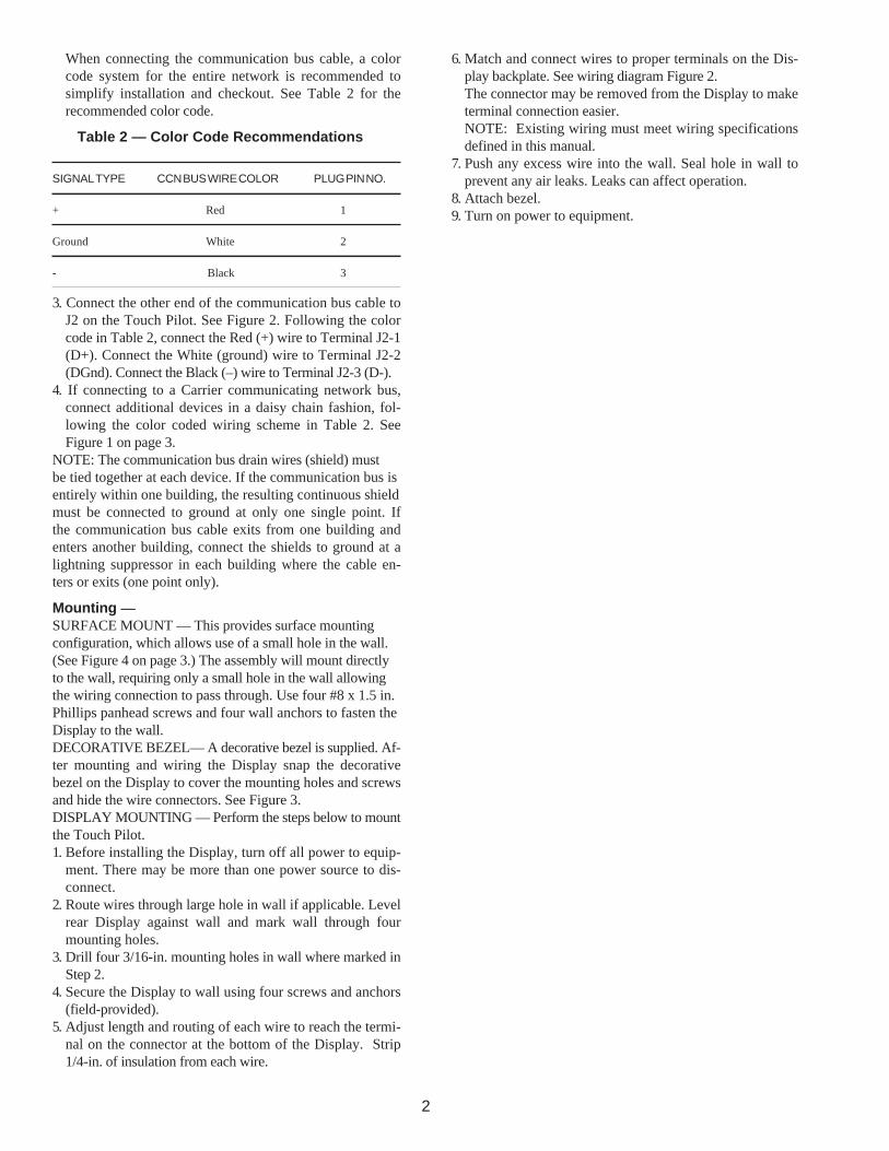
When connecting the communication bus cable, a colorcode system for the entire network is recommended tosimplify installation and checkout. See Table 2 for therecommended color code.
Table 2 — Color Code Recommendations
SIGNAL TYPE CCN BUS WIRE COLOR PLUG PIN NO.
+ Red 1
Ground White 2
- Black 3
3. Connect the other end of the communication bus cable toJ2 on the Touch Pilot. See Figure 2. Following the colorcode in Table 2, connect the Red (+) wire to Terminal J2-1(D+). Connect the White (ground) wire to Terminal J2-2(DGnd). Connect the Black (–) wire to Terminal J2-3 (D-).
4. If connecting to a Carrier communicating network bus,connect additional devices in a daisy chain fashion, fol-lowing the color coded wiring scheme in Table 2. SeeFigure 1 on page 3.
NOTE: The communication bus drain wires (shield) mustbe tied together at each device. If the communication bus isentirely within one building, the resulting continuous shieldmust be connected to ground at only one single point. Ifthe communication bus cable exits from one building andenters another building, connect the shields to ground at alightning suppressor in each building where the cable en-ters or exits (one point only).
Mounting —SURFACE MOUNT — This provides surface mountingconfiguration, which allows use of a small hole in the wall.(See Figure 4 on page 3.) The assembly will mount directlyto the wall, requiring only a small hole in the wall allowingthe wiring connection to pass through. Use four #8 x 1.5 in.Phillips panhead screws and four wall anchors to fasten theDisplay to the wall.DECORATIVE BEZEL— A decorative bezel is supplied. Af-ter mounting and wiring the Display snap the decorativebezel on the Display to cover the mounting holes and screwsand hide the wire connectors. See Figure 3.DISPLAY MOUNTING — Perform the steps below to mountthe Touch Pilot.1. Before installing the Display, turn off all power to equip-
ment. There may be more than one power source to dis-connect.
2. Route wires through large hole in wall if applicable. Levelrear Display against wall and mark wall through fourmounting holes.
3. Drill four 3/16-in. mounting holes in wall where marked inStep 2.
4. Secure the Display to wall using four screws and anchors(field-provided).
5. Adjust length and routing of each wire to reach the termi-nal on the connector at the bottom of the Display. Strip1/4-in. of insulation from each wire.
6. Match and connect wires to proper terminals on the Dis-play backplate. See wiring diagram Figure 2.The connector may be removed from the Display to maketerminal connection easier.NOTE: Existing wiring must meet wiring specificationsdefined in this manual.
7. Push any excess wire into the wall. Seal hole in wall toprevent any air leaks. Leaks can affect operation.
8. Attach bezel.9. Turn on power to equipment.

3
Figure 1 — Carrier Communicating Network (CCN) Bus Wiring
Figure 2 — Touch Pilot Wiring
1 2 3 6 5 4 1 2 3
COMM
GND
1000 FT MAXIMUM
DRAIN WIRE (TYP)
BLK (TYP)
WHT (TYP)
RED (TYP)
BYPASSCONTROLLER
ZONECONTROLLER
SYSTEMPILOT
ZONECONTROLLER
BRIDGE(RECOMMENDED)
1 2 3 1 2 3
CCNCCNCCN CCN
CHILLERDISPLAY
Figure 3 — Touch Pilot Bezel Figure 4 — Touch Pilot Surface Mounting
4
OPERATION
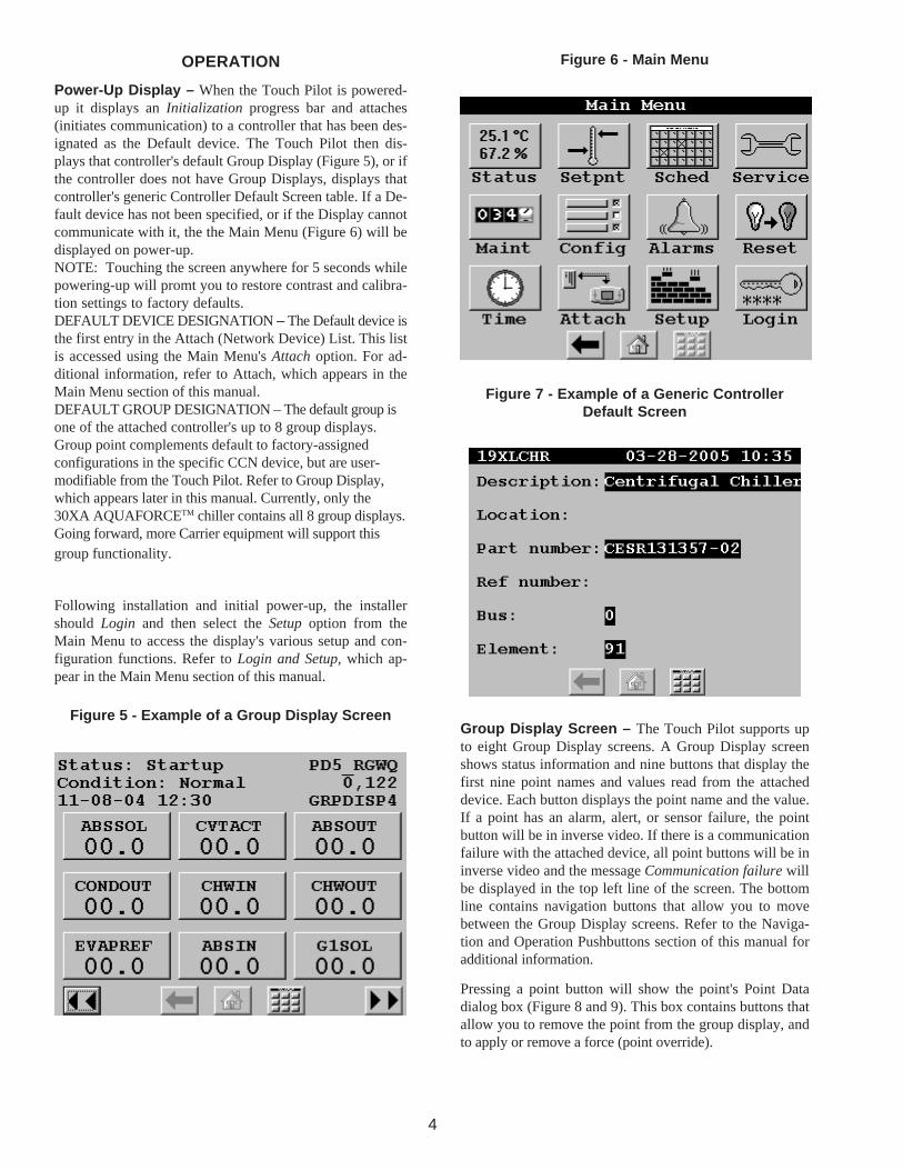
Power-Up Display – When the Touch Pilot is powered-up it displays an Initialization progress bar and attaches(initiates communication) to a controller that has been des-ignated as the Default device. The Touch Pilot then dis-plays that controller's default Group Display (Figure 5), or ifthe controller does not have Group Displays, displays thatcontroller's generic Controller Default Screen table. If a De-fault device has not been specified, or if the Display cannotcommunicate with it, the the Main Menu (Figure 6) will bedisplayed on power-up.NOTE: Touching the screen anywhere for 5 seconds whilepowering-up will promt you to restore contrast and calibra-tion settings to factory defaults.DEFAULT DEVICE DESIGNATION – The Default device isthe first entry in the Attach (Network Device) List. This listis accessed using the Main Menu's Attach option. For ad-ditional information, refer to Attach, which appears in theMain Menu section of this manual.DEFAULT GROUP DESIGNATION – The default group isone of the attached controller's up to 8 group displays.Group point complements default to factory-assignedconfigurations in the specific CCN device, but are user-modifiable from the Touch Pilot. Refer to Group Display,which appears later in this manual. Currently, only the30XA AQUAFORCETM chiller contains all 8 group displays.Going forward, more Carrier equipment will support thisgroup functionality.
Following installation and initial power-up, the installershould Login and then select the Setup option from theMain Menu to access the display's various setup and con-figuration functions. Refer to Login and Setup, which ap-pear in the Main Menu section of this manual.
Figure 5 - Example of a Group Display Screen
Figure 6 - Main Menu
Figure 7 - Example of a Generic ControllerDefault Screen
Group Display Screen – The Touch Pilot supports upto eight Group Display screens. A Group Display screenshows status information and nine buttons that display thefirst nine point names and values read from the attacheddevice. Each button displays the point name and the value.If a point has an alarm, alert, or sensor failure, the pointbutton will be in inverse video. If there is a communicationfailure with the attached device, all point buttons will be ininverse video and the message Communication failure willbe displayed in the top left line of the screen. The bottomline contains navigation buttons that allow you to movebetween the Group Display screens. Refer to the Naviga-tion and Operation Pushbuttons section of this manual foradditional information.
Pressing a point button will show the point's Point Datadialog box (Figure 8 and 9). This box contains buttons thatallow you to remove the point from the group display, andto apply or remove a force (point override).

5
TO REMOVE A POINT FROM A GROUP DISPLAY – Fromthe Point Data Dialog box, press the REMOVE button
and follow the prompts. The display will return to
the Group Display screen from which the point was re-moved, and the button corresponding to the deleted pointwill be blank and disabled.
TO ADD A POINT TO A GROUP DISPLAY – From theMain Menu, press the one of the table type buttons (Sta-tus, Setpnt, Service, Maint, or Config) and press the but-ton corresponding to the table that contains the point youwish to add to the group (the source point). Press the pointbutton to show the source point's Point Data dialog box(Figure 8 and 9). From the Point Data Dialog box, press the
ADD button . The Display will show the last Group
Display accessed. Use the and navigation but-
tons to access the destination Group Display. Press an ex-isting point button or a blank button to update the high-
lighted button with the source point's name. Press
to add the highlighted point to the group and return to thetable display.
Figure 8 - Point Data Dialog Box - Dynamic Point
Figure 9 - Point Data Dialog Box - Static Point
Navigation and Operation Pushbuttons – The TouchPilot contains the following pushbuttons to allow you tooperate the display and to navigate within and betweenscreens.
BACK – Returns to the next higher screen in the
hierarchy.
HOME – Displays the Default screen (Default Group
Display if one is available, the generic Controller DefaultScreen (Figure 7) if the attached device has no Group dis-plays, or the Main Menu if the display is not attached to adevice).
MAIN MENU – Displays the Main Menu screen. A
description of all Main Menu options can be found in theMain Menu section of this manual.
PREVIOUS – In a group of sequential screens of the
same type, moves to the next earlier screen in the group.
NEXT– In a group of sequential screens of the same
type, advances to the next screen in the group.
OK – Agrees with, or says “yes” to a prompt and
performs the appropriate processing.
NO – Rejects, or says “no” to a prompt and per-
forms the appropriate processing.
CANCEL – Terminates an ongoing action and re-
turns to the current screen without any other processing.
CLEAR DATA – Blanks the data value in a data
entry dialog box.
RESET DATA – Zeros the data value in a data entry
dialog box.
ADD – Adds a point to a Group Display screen.
REMOVE – Deletes a point from a Group Display
screen.
INC, DEC – Modify the value of a field within
its defined limits.
SCROLL UP, DOWN – Shifts the data on the
screen up or down by one item.
PAGE UP, DOWN – If the current table or list
has more data than will fit on the screen, replace the itemscurrently on the screen with the previous or next group ofitems.
FORCE – Begins the process of forcing or overriding
the value of a point.
AUTO – Begins the process of removing a force
from a point.
MODIFY – Begins the process of modifying a con-
figuration value.
ALARM INDICATOR LIGHT – The Touch Pilot fea-
tures an LED alarm indicator light that is activated when anew alarm condition has occurred on the Carrier communi-cating network. The alarm indicator light, located on theright side of the Display, remains activated until it is manu-ally reset using the Main Menu's Reset button. When theDisplay is in Network mode, the alarm indicator light doesnot indicate communication failure with the attached de-vice.
6
NOTE: In order for the Display to receive alarms from aCCN device, the CCN user interface bit in the device's AlarmRouting decision must be set to 1.
START/STOP BUTTON – The Touch Pilot includes an
equipment Start/Stop Button that enables you to start orstop the Chiller.NOTE: This button is not functional when the Display is inNetwork mode.
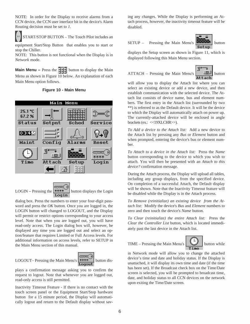
Main Menu – Press the button to display the Main
Menu as shown in Figure 10 below. An explanation of eachMain Menu option follows.
Figure 10 - Main Menu
LOGIN – Pressing the button displays the Login
dialog box. Press the numbers to enter your four-digit pass-word and press the OK button. Once you are logged in, theLOGIN button will changed to LOGOUT, and the Displaywill permit or restrict options corresponding to your accesslevel. Note that when you are logged out, you will haveread-only access. The Login dialog box will, however, bedisplayed any time you are logged out and select an op-tion/feature that requires Limited or Full Access levels. Foradditional information on access levels, refer to SETUP inthe Main Menu section of this manual.
LOGOUT– Pressing the Main Menu's button dis-
plays a confirmation message asking you to confirm therequest to logout. Note that whenever you are logged out,read-only access is still permitted.
Inactivity Timeout Feature - If there is no contact with thetouch screen panel or the Equipment Start/Stop hardwarebutton for a 15 minute period, the Display will automati-cally logout and return to the Default display without sav-
ing any changes. While the Display is performing an At-tach process, however, the inactivity timeout feature will bedisabled.
SETUP – Pressing the Main Menu's button
displays the Setup screen as shown in Figure 11, which isdisplayed following this Main Menu section.
ATTACH – Pressing the Main Menu's button
will allow you to display the Attach list where you canselect an existing device or add a new device, and thenestablish communication with the selected device. The At-tach list consists of device name, bus and element num-bers. The first entry in the Attach list (surrounded by two**) is referred to as the Default device. It will be the deviceto which the Display will automatically attach on power up.The currently-attached device will be enclosed in anglebrackets (ex.: <<19XLCHR>>).
To Add a device to the Attach list: Add a new device tothe Attach list by pressing any Bus or Element button andwhen prompted, entering the device's bus or element num-ber.
To Attach to a device in the Attach list: Press the Namebutton corresponding to the device to which you wish toattach. You will then be presented with an Attach to thisdevice? confirmation message.
During the Attach process, the Display will upload all tables,including any group displays, from the specified device.On completion of a successful Attach, the Default displaywill be shown. Note that the Inactivity Timeout feature willbe disabled while the Display is in the Attach process.
To Remove (reinitialize) an existing device from the At-tach list: Modify the device's Bus and Element numbers tozero and then touch the device's Name button.
To Clear (reinitialize) the entire Attach list: Press theClear the Controller List button, which is located immedi-ately past the last device in the Attach list.
TIME – Pressing the Main Menu's button while
in Network mode will allow you to change the attacheddevice’s time and date and holiday status. If the Display isunattached, it will display its own time and date (if the timehas been set). If the Broadcast check box on the Time/Datescreen is selected, you will be prompted to broadcast time,date, and holiday status to all CCN devices on the networkupon exiting the Time/Date screen.
7
ALARMS – Pressing the Main Menu's button
will allow you to display device alarms from a selected AlarmHistory table in the attached device or network alarms fromthe CCN. To view device alarms, use the Alarm Table but-tons (if the device has 2 or more alarm tables) or theHistory button (if there is only 1 alarm table). To viewalarms from the CCN, use the Network button. Note that ifthe Display is unattached or the attached device has noAlarm History tables, the Table List screen will only con-tain a Network button. Alarm History is a static screen. Torefresh the alarm list, you must exit and re-select the Alarmsoption.
RESET – Pressing the Main Menu's button will
allow you to turn off the Display’s alarm indicator light.The light will stay off until a new alarm condition is de-tected.
SCHED – Pressing the Main Menu's button al-
lows you to display a CCN time schedule from the attacheddevice. If the attached device has just one time schedule,the Display will bring up the Time Schedule screen. If thedevice has multiple time schedules, the Display will show alist of schedules from which you can select the one youwish to access. The Time Schedule screen consists of eightbuttons, one for each occupancy period. Press a periodbutton to show the Period Edit dialog box for that period.You will be prompted to save changes upon exiting theTime Schedule screen.
STATUS, SETPNT, SERVICE, MAINT OR CONFIG – Press-
ing the
buttons allows you to display a status display,
setpoint, service configuration, maintenance, or configura-tion table from the attached device. If there is just onetable of that type the Display will bring up the Table screen.If the device has multiple tables of that type, the Displaywill show a list of tables from which you can select the oneyou wish to access.As you make changes to values in these tables, the newvalues will be displayed. On pressing a Navigationpushbutton to exit the current screen, a confirmation mes-
sage will be displayed. Pressing will save and down-
load the new values to the attached device. Pressing
will exit the screen without saving or downloading the modi-
fied values. Pressing will cancel the changes and re-
turn you to the screen for further changes.
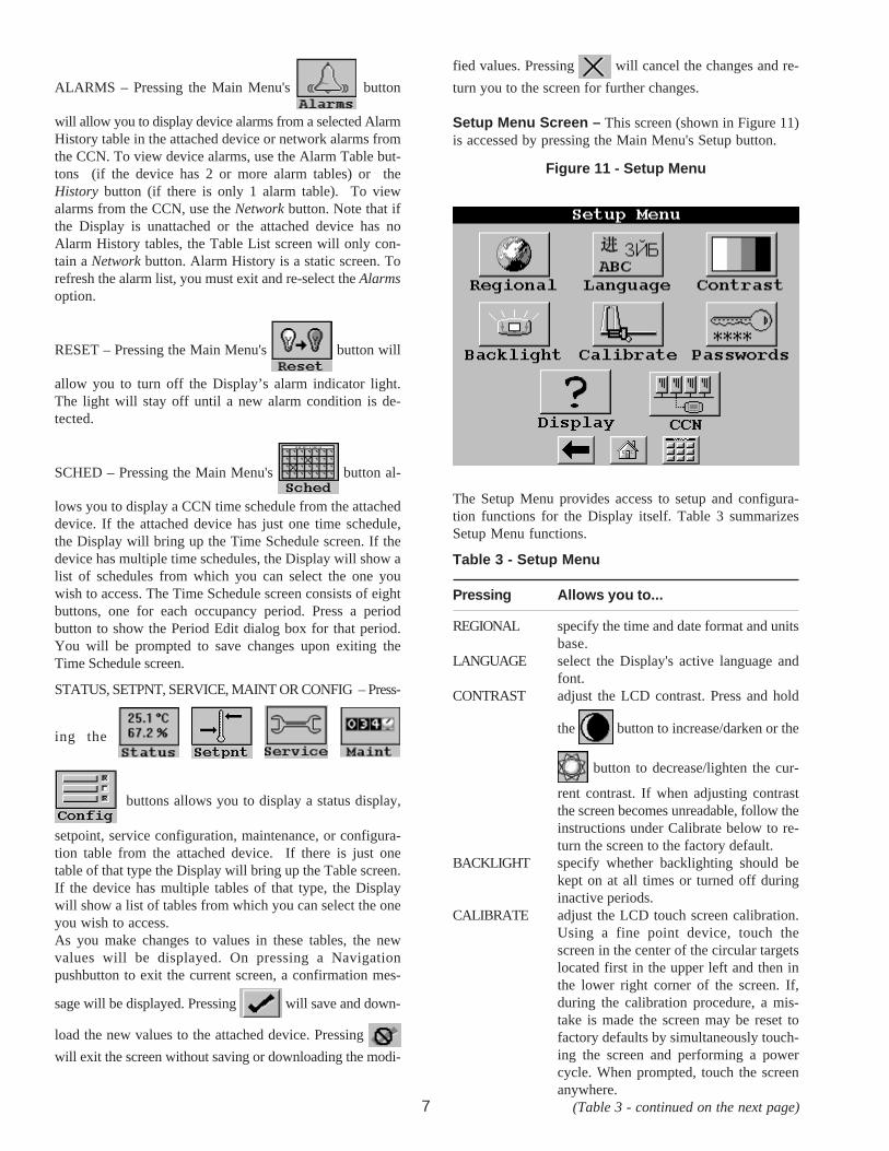
Setup Menu Screen – This screen (shown in Figure 11)is accessed by pressing the Main Menu's Setup button.
Figure 11 - Setup Menu
The Setup Menu provides access to setup and configura-tion functions for the Display itself. Table 3 summarizesSetup Menu functions.
Table 3 - Setup Menu
Pressing Allows you to...
REGIONAL specify the time and date format and unitsbase.
LANGUAGE select the Display's active language andfont.
CONTRAST adjust the LCD contrast. Press and hold
the button to increase/darken or the
button to decrease/lighten the cur-
rent contrast. If when adjusting contrastthe screen becomes unreadable, follow theinstructions under Calibrate below to re-turn the screen to the factory default.
BACKLIGHT specify whether backlighting should bekept on at all times or turned off duringinactive periods.
CALIBRATE adjust the LCD touch screen calibration.Using a fine point device, touch thescreen in the center of the circular targetslocated first in the upper left and then inthe lower right corner of the screen. If,during the calibration procedure, a mis-take is made the screen may be reset tofactory defaults by simultaneously touch-ing the screen and performing a powercycle. When prompted, touch the screenanywhere.
(Table 3 - continued on the next page)
8
Table 3 - Setup Menu (continued)
Pressing Allows you to...
PASSWORDS configure limited and full logged-in accesssystem passwords. Note that you mustbe logged in with full access to view andchange the passwords. All passwordsmust consist of 4-digits, which you canenter using the numeric keypad.
Access levels and associated privilegesare as follows:
Limited Logged-in Access - provides youwith read/write access to all availabletables (except service configuration tables,where you will not be permitted to modifypoint data, and Group Display tables,where you will not be permitted to addpoints.) This access level also providesread/write access to all Display Setup prop-erties except Display, CCN, and Password.
Full Logged-in Access - provides youwith read/write access to all availabletables for the attached device and all Dis-play properties.
Note that if you do not log in, you willhave read-only access to all tables in theattached device. You will be prompted tolog in when attempting to access pass-word-required functions.
DISPLAY view data from the Display's Ctlr-ID Tableand specify the Display's OperatingMode. Equipment mode provides accessonly to the Default device or to the de-vice currently connected to the Display'sRS-485 connector (via the Local Equip-ment Network (LEN) Bus). Network modeprovides access to all devices on the CCNBus connected to the Display's RS-485connector.NOTE: When changing the operatingmode, a power cycle is required in orderfor the new operating mode to take effect.
CCN view and modify the following CCN data:address and baud rate, alarmacknowledger and broadcastacknowledger designation.
CONFIGURATION TABLES
Display operation is controlled by decisions entered in thethe following configuration tables, which are accessible froma Carrier front end such as the Network Service Tool orComfortVIEW:• CtlrID – Controller Identification Configuration Table• USERCONF – User Configuration Table
NOTE: You should always perform an Upload to obtain the
latest configuration before making configuration tablechanges.
User Configuration (USERCONF) Table – The UserConfiguration table is shown in Figure 12. Each decision isexplained below.
Backlight Always On? – Use this decision to indicatewhether to keep the backlight on continuously, or whetherto turn it off after 60 seconds with no activity.
Allowable Entries: No/Yes (No=0 or Yes=1)Default Value: No
Full Access Password – Use this decision to specify thefull access password. Refer to Table 1 - Setup Menu foradditional information on passwords.
Allowable Entries: 0 through 9999Default Value: 3333
Limited Access Password – Use this decision to specifythe limited access password.
Allowable Entries: 0 through 9999Default Value: 2222
Active Language – Use this decision to specify the Display'sactive language. All translatable text will be displayed inthis language.
Allowable Entries: 0 through 1Default Value: 0
Time Format – Use this decision to specify the format fordisplay of time.
Allowable Entries: 0 = H:MM AM/PM without leadingzero1 = HH:MM with leading zero whennecessary
Default Value: 0
Date Format – Use this decision to specify the format fordisplay of date.
Allowable Entries: 0 = MM-DD-YYYY with leading zerowhen necessary1 = DD-MM-YYYY with leading zerowhen necessary2 = YYYY-MM-DD
Default Value: 0
Units Base – Use this decision to specify engineeringunits.
Allowable Entries: 0 = U.S.1 = Metric
Default Value: 0
Contrast Control – Use this decision to enable or disable

9
the Display's auto contrast adjustment feature. When en-abled, the Display's contrast will be automatically adjustedas required, based on temperature.
Allowable Entries: 0 = Manual(Auto Contrast Adjustment Disabled)1 = Auto(Auto Contrast Adjustment Enabled)
Default Value: 1
Network Mode – Use this decision to set the Display'soperating mode. For additional information on operatingmode, refer to Display in Table 1 - Setup Menu. This deci-sion will be ignored and the mode will default to Equipmentwhen the Display is connected to a device (the LEN Bus).
NOTE: A power cycle is required for this decision to takeeffect.
Allowable Entries: 0 = Equipment Mode1 = Network Mode
Default Value: 0
Network SettingsAlarm Acknowledger – Use this decision to specifywhether the Touch Pilot will act as the alarm acknowledgerfor its CCN. There must be only one alarm acknowledgerper CCN. Therefore, if another CCN device such asComfortVIEW, the Autodial Gateway or TeLINK is alreadyset as the Alarm Acknowledger for the CCN then this deci-sion should be set to No.
NOTE: The Display must be in Network mode and con-nected to the primary CCN Bus and this decision set to Yesfor alarm acknowledgement to be enabled.
Allowable Entries: 0 = No1 = Yes
Default Value: 0
Broadcast Acknowledger – Use this decision to indicatewhether the Touch Pilot will act as the broadcastacknowledger for its CCN Bus. There must be 1 (and only1) broadcast acknowledger per CCN Bus.NOTE: The Display must be in Network mode and this
Figure 12 - User (USERCONF) ConfigurationTable
10
decision set to Yes for broadcast acknowledgement to beenabled.
Allowable Entries: 0 = No1 = Yes
Default Value: 0
Equipment CCN Address –When in equipment mode (USERCONF Table's NetworkMode decision is set to Disable), the Bus Number andElement Number decisions are used to specify the CCN ad-dress of the piece of equipment to which you wish to com-municate. You must perform an Attach or cycle power forchanges to these decisions to take effect. These decisionswill be ignored when the Display is connected to the LENbus or in Network mode. In network mode, you specify thebus and element number of the equipment to which youwish to communicate using the Display's Attach function.For additional information, see Attach in the Main Menusection of this manual.
NOTE: In Network mode, these decisions will be overwrit-ten with the Default device address if it is changed throughthe Attach process.
Bus Number – Use this decision to specify the EquipmentController bus number .
Allowable Entries: 0 through 239Default Value: 0
Element Number – Use this decision to specify the Equip-ment Controller element number .
Allowable Entries: 1 through 239Default Value: 1
Control VariablesUse the next 4 decisions to specify the names of the CCNequipment variables that will be used to implement the Start/Stop Control and Alarm Indication functionality.
Equipment Status – This decision is used in conjunctionwith the Display's Start/Stop button. Enter the CCN variablename of the equipment input point to which the on/off sta-tus indicator is connected. This name can be obtained fromthe CCN equipment's status display table. This decision willbe ignored when the Display is in network mode.
Allowable Entries: Up to 8 character CCN variable nameValid characters include A to Z,0 to 9, dash and underscore
Default Value: blank = Disable START/STOP control
Equipment Start/Stop – This decision is used in conjunc-tion with the Display's Start/Stop button. Enter the CCNvariable name of the equipment point to which the Start/Stop output point is connected. If you press the buttonwhile in equipment mode, the Display will first look at theequipment point's status (in accordance with the variablename you entered in the Equipment Status decision above)and then start or stop the equipment point that you specifyin this decision. This name can be obtained from the CCN
equipment's status display table. This decision will be ig-nored when the Display is in network mode.
Allowable Entries: Up to 8 character CCN variable nameValid characters include A to Z,0 to 9, dash and underscore
Default Value: blank = Disable START/STOP control
Alarm Status – This decision is used in conjunction withthe Display's Alarm Indicator light. When in equipmentmode, the Display will read the value of the input point thatyou specify in this decision and will turn the indicator lighton or off accordingly. Enter the CCN variable name of theequipment input point to which the alarm status indicator isconnected. This name can be obtained from the attacheddevice's status display table. This decision will be ignoredwhen the Display is in network mode or attached to aAquaForce™ chiller.
Allowable Entries: Up to 8 character CCN variable nameValid characters include A to Z,0 to 9, dash and underscore
Default Value: blank
Alarm Reset – This decision is used in conjunction withthe Reset button on the Main Menu. When in equipmentmode, the Display will reset the alarm status equipment pointthat you specify in this decision and will turn off the AlarmIndicator light when the Reset button is pressed. This deci-sion will be ignored when the Display is in network mode orattached to an AquaForce chiller.
Allowable Entries: Up to 8 character CCN variable nameValid characters include A to Z,0 to 9, dash and underscore
Default Value: blank