
Installation and Operating Manual - Dieselheating.comdieselheating.com/Hurricane Zephyr...
98
from Calcutt Boats Installation and Operating Manual Hurricane® Zephyr™ HW Diesel Heating System for Boats
Transcript of Installation and Operating Manual - Dieselheating.comdieselheating.com/Hurricane Zephyr...

from Calcutt Boats
Installation and Operating Manual
Hurricane® Zephyr™ HW
Diesel Heating System for Boats
Manual Issue Date/Copyright © December 2013
MANUFACTURED BY: SOLE EUROPEAN DISTRIBUTORS:
International Thermal Research Calcutt Boats Ltd.
2431 Simpson Road, Tomlow Road, Stockton,
Richmond, BC, Canada, V6X 2R2 Southam, CV47 8HX, UK
Tel: +1 604-278-1272 Tel: +44 1926 813757
Fax: +1 604-278-1274 Fax: +44 1926 814091
Email: [email protected] Email: [email protected]
Website: www.itrheat.com Website: www.dieselheating.com
All rights reserved. No part of this manual may be reproduced or transmitted in any form by any means, electronic or mechanical, including photocopying and recording, information storage, retrieval, or transmission, without permission in writing from International Thermal Research and/or Calcutt Boats Ltd.
Disclaimer:
Due to our commitment for quality and ongoing product improvement, ITR & Calcutt Boats reserve the right to modify or change without notice, any materials, applications, equipment, accessories, and/or prices. All measurements and weights are approximate.
Read and save these instructions for future reference.

International Thermal Research i
Table of Contents Section 1, Overview.................................................... 1
1.1 Unpacking the Heating System...........................2 1.2 Protect Your Warranty.......................................2 1.3 Heater Features ...............................................3 1.4 Critical Factors .................................................4 1.5 Equipment, Tools and Skills ...............................5 1.6 Testing and Inspection ......................................6
Section 2, Mounting the Heater Unit ........................... 7
2.1 Before You Begin..............................................7 2.2 Mounting Location ............................................8 2.3 What NOT to Do .............................................10
Section 3, Installing the Exhaust System.................. 13
3.1 Before You Begin............................................13 3.2 Mounting Location ..........................................13 3.3 What NOT to Do .............................................15 3.4 Installation Procedure .....................................16
Section 4, Installing the Fuel System........................ 19
4.1 Before You Begin............................................19 4.2 Fuel System Installation ..................................19 4.3 What NOT to Do .............................................20 4.4 Installation Procedure .....................................21
Section 5, Installing Cabin Fans................................ 23
5.1 Before You Begin............................................23 5.2 Fan System Operation.....................................24 5.3 What NOT to Do .............................................27 5.4 Mounting Locations.........................................27 5.5 Installation Procedure .....................................28
Section 6, Wiring the Electrical System .................... 31
6.1 Before You Begin............................................31 6.2 Electrical Noise...............................................31 6.3 12 VDC .........................................................33 6.4 120/240 VAC .................................................33 6.5 Electrical Components .....................................35 6.6 What NOT to Do .............................................38 6.7 Procedure......................................................38
Table of Contents
ii Installation Manual for Hurricane® Zephyr™ HW Heating System
Section 7, Plumbing the System................................43
7.1 Before You Begin ........................................... 43 7.2 Plumbing Components .................................... 43 7.3 What NOT to Do ............................................ 45 7.4 Installation Procedure..................................... 45
Section 8, Filling and Testing the Circulation System 49
8.1 Before You Begin ........................................... 49 8.2 What NOT to Do ............................................ 49 8.3 Procedure for Expansion Tank Filling Method...... 50 8.4 Procedure for Manifold Filling Method................ 51
Section 9, Domestic Hot Water Heating.....................55
9.1 Before You Begin ........................................... 55 9.2 Domestic Hot Water System............................ 56
Section 10, Engine Heat Management .......................57
10.1 Engine Waste Heat Function ............................ 57 10.2 Waste Heat Function ...................................... 58 10.3 Engine Pre-heat Installation Procedure.............. 59
Section 11, Operation................................................61
11.1 Starting the Heater ........................................ 61 11.2 Signs of Normal Operation .............................. 61 11.3 Main Control Board Operation .......................... 62 11.4 Stopping the Heater for Seasonal Purposes........ 63 11.5 Using the Electric Heating Element ................... 63 11.6 Stopping the Heater for Maintenance ................ 63 11.7 Resetting After a Fault .................................... 64
Section 12, Troubleshooting......................................67
12.1 Overview ...................................................... 67 12.2 Power On (Green) .......................................... 67 12.3 Burner On..................................................... 67 12.4 V - Service Switch Off ..................................... 68 12.5 9 - Remote Switch Off..................................... 68 12.6 < - Heater Cycling (Normal Operation)...................... 68 12.7 T - Thermostats Off (Normal Operation) ............ 69 12.8 0 - Voltage Low or High................................... 69 12.9 1 – Overheat .................................................. 70 12.10 2 - Fuse Blown.............................................. 70 12.11 3 - Fuel Pump/Solenoid ................................... 71 12.12 4 – Igniter .................................................... 71 12.13 5 - Combustion Fan........................................ 72 12.14 6 - Water Pump ............................................. 72 12.15 7 - Flame Out ................................................ 73
Table of Contents
International Thermal Research iii
12.16 8 – Compressor ..............................................74 12.17 ) - Bypass Mode .............................................75 12.18 Water Pump On (Green) ..................................75 12.19 LCD Readout Remote Panel (optional) ...............75 12.20 Flame Sensor Module ......................................75 12.21 Test Points ....................................................77 12.22 Reduced Output .............................................78 12.23 Dirty Exhaust.................................................78 12.24 Carbon Monoxide Dangers ...............................80
Section 13, Maintenance........................................... 81
13.1 The First Few Weeks .......................................81 13.2 Adding Coolant...............................................81 13.3 Nozzle ..........................................................82 13.4 Fuel Lines and Filter........................................83 13.5 Combustion Chamber......................................83 13.6 Checking Hoses and Tubes...............................83 13.7 Electrical System............................................83 13.8 Recommended Spare Parts ..............................84 13.9 Protecting Hydronic Heating Systems ................85
Section 14, Warranty and Service............................. 87
14.1 Attention Purchaser and Installer ......................87 14.2 Limited Warranty............................................88 14.3 Owner’s Responsibilities ..................................88 14.4 Not Covered Under Warranty ...........................89 14.5 Customer Service Calls....................................90 14.6 Returns.........................................................90 14.7 Telephone Service ..........................................91
Table of Contents
iv Installation Manual for Hurricane® Zephyr™ HW Heating System
List of Figures
Figure 1-1: Hurricane® Zephyr™ HW external dimensions ..1 Figure 1-2: Typical Zephyr system series layout, with three
cabin fans and optional summer loop................6 Figure 2-1: Hurricane® Zephyr™ HW typical installation
showing the dual fresh-air intake and exhaust thru hull fitting ..............................................9
Figure 2-2: Heater Mounting Bracket Configuration .......... 11 Figure 3-1: Installing a Marine Exhaust Goose Neck System ...................................................... 17 Figure 4-1: Fuel Connection Schematic........................... 21 Figure 5-1: Wiring the Fan’s Aquastat ............................ 25 Figure 5-2: Mounting a Spacesaver Fan .......................... 29 Figure 5-3: Installing a Relay for an Additional Fan .......... 29 Figure 6-1: Sample Wiring Diagram for Electrical Elements 34 Figure 6-2: V2001 Control Board ................................... 37 Figure 6-3: Wiring for a Fan Speed Switch ...................... 40 Figure 6-3a: Wiring for a Narrowboat Supplementary Kit .. 40 Figure 6-4: Wiring Diagram V2001................................. 41 Figure 7-1: Three Approved Methods of Installing Heater
Hose.......................................................... 46 Figure 7-2: Single loop system with three fans and optional
summer loop............................................... 47 Figure 7-3: Generic Parallel Plumbed System .................. 47 Figure 8-1: Filling system using “manifold method” system
shown with optional summer loop valve .......... 53 Figure 9-1: Single loop system with three fans and optional
summer loop............................................... 56 Figure 10-1: Single loop series with optional summer loop
and engine coolant flow direction Figure 11-1: Hurricane Zephyr front and top components . 64 Figure 11-2: Hurricane Zephyr side components .............. 65
International Thermal Research 1
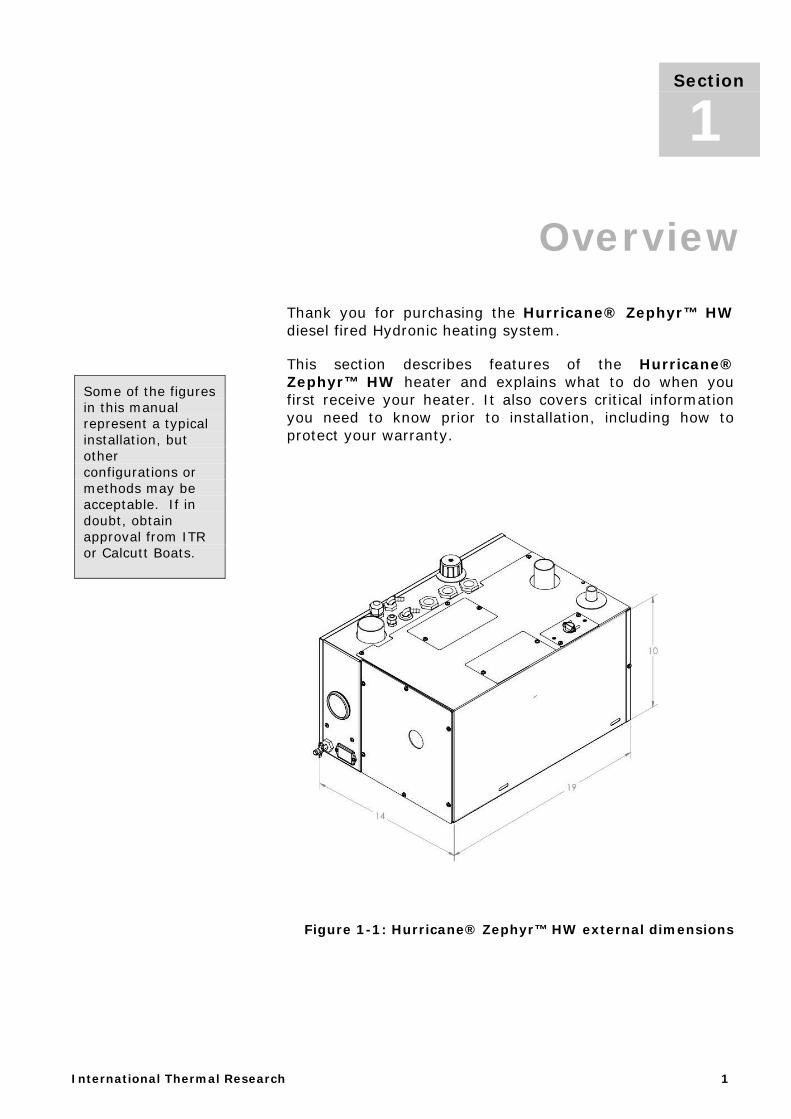
Section 1, Overview Thank you for purchasing the Hurricane® Zephyr™ HW diesel fired Hydronic heating system.
This section describes features of the Hurricane® Zephyr™ HW heater and explains what to do when you first receive your heater. It also covers critical information you need to know prior to installation, including how to protect your warranty.
Figure 1-1: Hurricane® Zephyr™ HW external dimensions
Section
1
Some of the figures in this manual represent a typical installation, but other configurations or methods may be acceptable. If in doubt, obtain approval from ITR or Calcutt Boats.

Section 1, Overview
2 Installation Manual for Hurricane® Zephyr™ HW Heating System
1.1 Unpacking the Heating System
When you receive your Hurricane® Zephyr™ HW heater:
1. Unpack it carefully.
2. Check each component against the provided parts list to ensure that you have everything, and that all parts are undamaged.
3. If you discover any missing or defective parts, call ITR or Calcutt Boats immediately.
4. If you are not installing the heater right away, secure all components so none will be misplaced.
5. Before installing the heater, read the rest of this manual. It contains critical information for a proper installation.
It is important to follow the installation procedures in this manual to ensure maximum performance of the heater and that you and/or your customers enjoy a warm, comfortable environment and plenty of hot water when needed.
1.2 Protect Your Warranty
This document reflects approved installation techniques, methods, and materials, and applies only to ITR equipment. The heater is only guaranteed by Calcutt Boats and ITR if the entire system has been installed according to the requirements and recommendations set out here.
Warranty coverage will not be extended to ITR heaters and system components used in an improper installation. Use of unapproved materials, equipment, or installation procedures will void the warranty for the entire heating system. Calcutt Boats and/or ITR do not accept liability for any damage or loss of service resulting from unapproved installations and/or modifications.
NOTICE
Section 1, Overview
International Thermal Research 3
1.3 Heater Features
The Hurricane® Zephyr™ HW is an advanced hydronic heater with many advantages over forced-air systems. The Zephyr™ provides space heating using a “heat-transfer fluid” pumped to fan-equipped, radiator-style heat-exchangers. The same “hot” fluid is circulated through an internally mounted, flat-plate heat-exchanger to provide a continuous supply of domestic hot water. The heater runs on 12VDC power, using a diesel fired burner to maintain the temperature of the heater fluid. The Zephyr™ can use waste heat from the engine coolant running it through an internal heat exchanger; and the addition of an optional secondary water pump also allows for pre-heating of the engine.
Other features and benefits of the Hurricane® Zephyr™ HW heating system include:
• 1500 Watt, 240 VAC electric element for a supplemental or backup heating source when the boat is connected to a power source.
• High-temperature stainless steel burner and water jacket to prevent premature warping or burnout.
• Temperature gauge to measure coolant temperature and indicate when the heater has reached operating temperature.
• Insulated enclosure to retain heat and minimize noise.
• Easy installation and field serviceability, with hookups and connections readily accessible from the top of the heater.
• Quiet operation and low power consumption.
• Low-pressure fuel system with built-in fuel pump.
• Fuel-efficient burner compatible with a wide variety of diesel-based fuels.
• Smoke and smell free exhaust.
• Sealed, fan assisted combustion chamber, designed to use outside air through a direct ventilation hook-up.
• Simple, low amperage draw ignition.
Hurricane® Zephyr™ HW ADVANTAGES
• Efficient • Clean • Quiet • Compact • Safe • Rugged • Reliable • Economical
Section 1, Overview
4 Installation Manual for Hurricane® Zephyr™ HW Heating System
• Return fuel line to eliminate air in the system and prevent nuisance shutdowns.
• Electronically-controlled system with:
o Automatic safety shutdown. o Manual reset overheat temperature sensor and a
thermal cutoff for overheat protection. o LED display control panel for diagnostics. o Patented, proprietary flame sensor
• Remote control panel with on/off reset button, LCD digital readout, and audible alarm.
• Heating control for up to four separate space heating zones, each with its own optional thermostat.
• On demand, continuous domestic water heating without the need for hot water storage.
• Use of engine waste heat to provide system heating.
• Engine pre-heating capabilities (using an optional external pump).
1.4 Critical Factors
The key factors to keep in mind when planning and installing the heater are:
• Location restrictions for the heater, electrical control box, and exhaust outlet (to reduce noise, vibration, heat loss, etc.).
• Length, routing, and sizing of the hot fluid lines, fuel lines, air-inlet venting and tubing, exhaust piping, and wiring.
• Outside air - direct, unrestricted air intake requires a draw of outside air for combustion.
• Ability to easily access and service the product, especially fuel, plumbing, and electrical systems.
• System testing and inspection procedures as explained in the supplied inspection check sheets.
Please pay attention to alerts of “Danger” “Warning” “Caution” and “Notice” in this manual.
Section 1, Overview
International Thermal Research 5
1.5 Equipment, Tools, and Skills
If you are the installer, you must be qualified and authorized to perform the installation; this requires mechanical aptitude and electrical knowledge. The installation of the Hurricane® Zephyr™ HW shall be in accordance with local regulations. Make sure you comply with existing industry practices, using the highest and most recent standards and codes. Good workmanship is essential. Please refer back to Section 1.2, Protect Your Warranty.
You will need the following to install the heating system:
• Standard tools normally available in a well-equipped workshop.
• Approved fasteners (used with the supplied mounting hardware) for securely mounting the heater.
• Appropriate exhaust piping that is a maximum of 12’ long with no bends.
• Combustion fan intake hose, though-hull adapter, and clamps.
• ITR muffler.
• Approved 1/4”/6.4mm ID supply and return fuel lines, rubber or copper.
• Enough heater hose to connect the heater to the expansion tank, the expansion tank to the circulation pump, and for appropriate runs to and from each interior fan. If engine waste heat is recycled into the system, heater hose is required to connect the heater to the engine block.
• Clamps to secure all heater hose and fuel hose connections.
• Expansion tank with a maximum 7psi/0.5bar radiator cap, or non pressurized system with simple header tank.
• Overflow tank to connect to expansion tank, with clear plastic 3/8”/10mm hose; tank must be heavy-duty plastic, with a screw-down cap, and sturdy enough to mount firmly to a vertical surface.
• Up to four thermostats (DC compatible) to allow temperature regulation of the four heating zones.
Section 1, Overview
6 Installation Manual for Hurricane® Zephyr™ HW Heating System
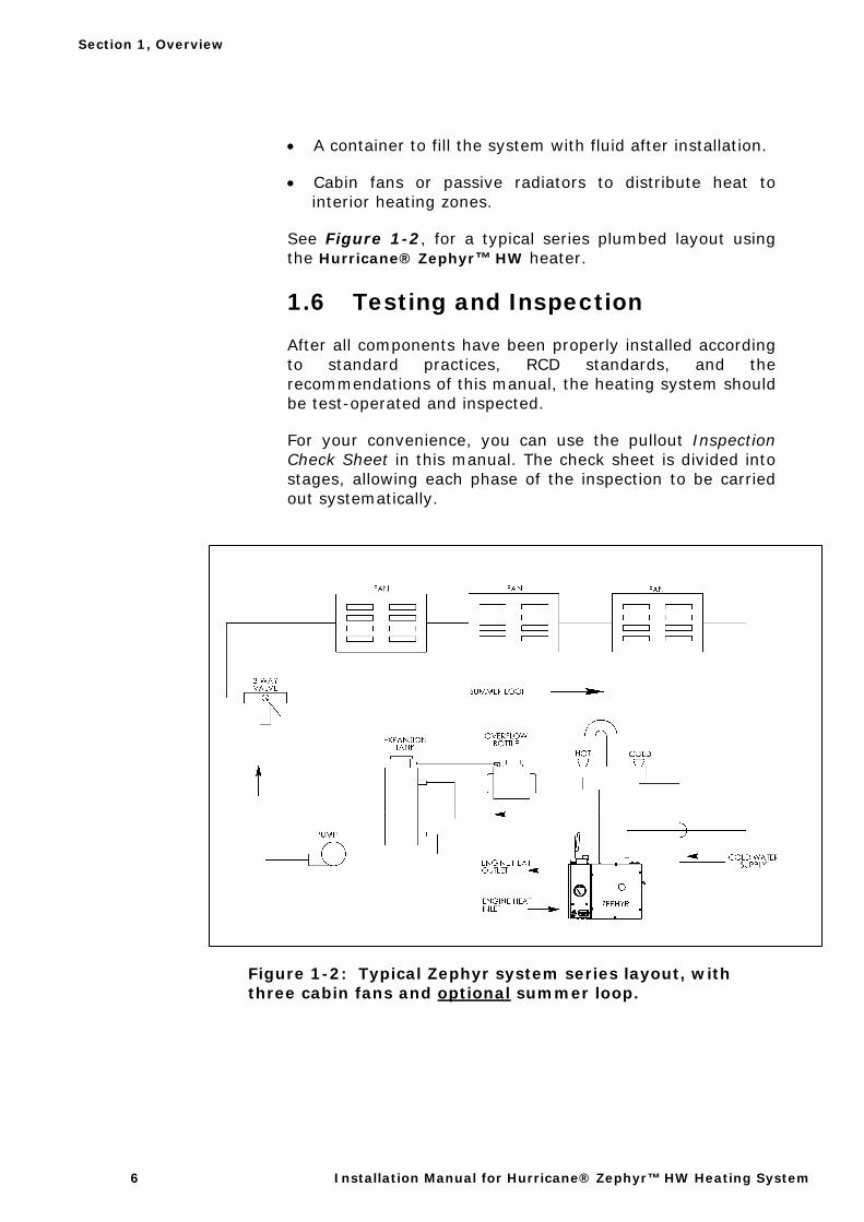
• A container to fill the system with fluid after installation.
• Cabin fans or passive radiators to distribute heat to interior heating zones.
See Figure 1-2, for a typical series plumbed layout using the Hurricane® Zephyr™ HW heater.
1.6 Testing and Inspection
After all components have been properly installed according to standard practices, RCD standards, and the recommendations of this manual, the heating system should be test-operated and inspected.
For your convenience, you can use the pullout Inspection Check Sheet in this manual. The check sheet is divided into stages, allowing each phase of the inspection to be carried out systematically.
Figure 1-2: Typical Zephyr system series layout, with three cabin fans and optional summer loop.
International Thermal Research 7
Section 1, Mounting the Heater Unit
2.1 Before You Begin
Plan the location of the heater and all its major components in advance to ensure the chosen locations are appropriate and within technical specifications.
Consider the following factors to help you decide exactly where to mount the heating system:
• Heater weight when full. • Ventilation requirements. • Exhaust outlet location and maximum acceptable exhaust length. • Potential for vibration and jarring. • Fuel storage location. • Most efficient plumbing runs. • Safe and convenient access for maintenance. • Number and location of interior fans. • Location of other equipment to be installed or connected to the
heater, including control box, expansion tank, overflow bottle and circulation pump. Note: the circulation pump must be mounted in a location that is below the expansion tank.
Make sure you are familiar with Section 1, Overview of this manual. If the system is not installed according to specifications and with the correct equipment, your heater may not operate properly, safety may be compromised, and your warranty may be voided.
Section
2
! WARNING
Section 2, Mounting the Heater Unit
8 Installation Manual for Hurricane® Zephyr™ HW Heating System
2.2 Mounting Location
• Mounting location must be able to support double the gross weight of the heater when full (i.e. 70 lbs x 2 = 140 lbs/63.5 kg).
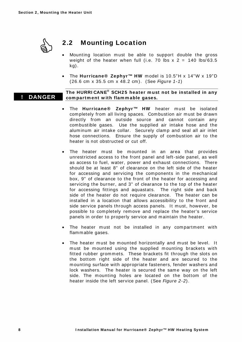
• The Hurricane® Zephyr™ HW model is 10.5”H x 14”W x 19”D (26.6 cm x 35.5 cm x 48.2 cm). (See Figure 1-1)
The HURRICANE® SCH25 heater must not be installed in any compartment with flammable gases.
• The Hurricane® Zephyr™ HW heater must be isolated completely from all living spaces. Combustion air must be drawn directly from an outside source and cannot contain any combustible gases. Use the supplied air intake hose and the aluminum air intake collar. Securely clamp and seal all air inlet hose connections. Ensure the supply of combustion air to the heater is not obstructed or cut off.
• The heater must be mounted in an area that provides unrestricted access to the front panel and left-side panel, as well as access to fuel, water, power and exhaust connections. There should be at least 8” of clearance on the left side of the heater for accessing and servicing the components in the mechanical box, 9” of clearance to the front of the heater for accessing and servicing the burner, and 3” of clearance to the top of the heater for accessing fittings and aquastats. The right side and back side of the heater do not require clearance. The heater can be installed in a location that allows accessibility to the front and side service panels through access panels. It must, however, be possible to completely remove and replace the heater's service panels in order to properly service and maintain the heater.
• The heater must not be installed in any compartment with flammable gases.
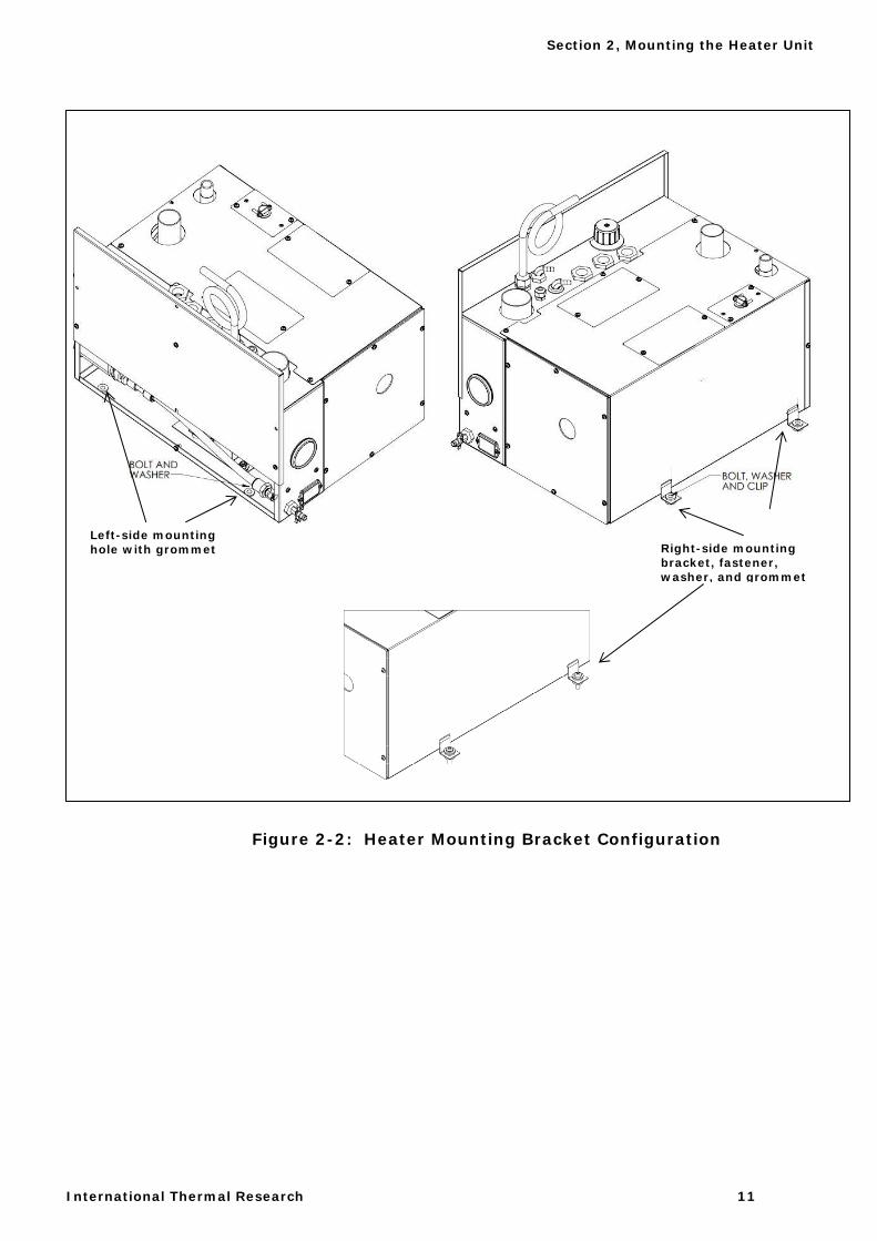
• The heater must be mounted horizontally and must be level. It must be mounted using the supplied mounting brackets with fitted rubber grommets. These brackets fit through the slots on the bottom right side of the heater and are secured to the mounting surface with appropriate fasteners, fender washers and lock washers. The heater is secured the same way on the left side. The mounting holes are located on the bottom of the heater inside the left service panel. (See Figure 2-2).
! DANGER
Section 2, Mounting the Heater Unit
International Thermal Research 9
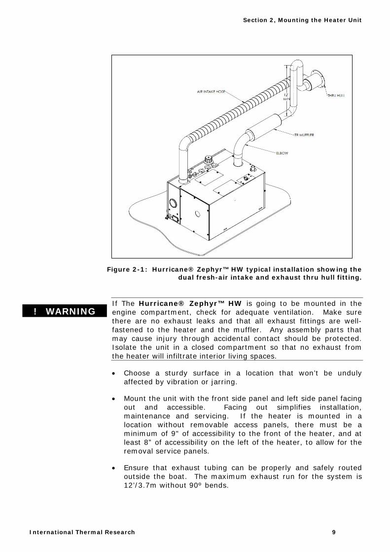
Figure 2-1: Hurricane® Zephyr™ HW typical installation showing the
dual fresh-air intake and exhaust thru hull fitting.
If The Hurricane® Zephyr™ HW is going to be mounted in the engine compartment, check for adequate ventilation. Make sure there are no exhaust leaks and that all exhaust fittings are well-fastened to the heater and the muffler. Any assembly parts that may cause injury through accidental contact should be protected. Isolate the unit in a closed compartment so that no exhaust from the heater will infiltrate interior living spaces.
• Choose a sturdy surface in a location that won’t be unduly affected by vibration or jarring.
• Mount the unit with the front side panel and left side panel facing out and accessible. Facing out simplifies installation, maintenance and servicing. If the heater is mounted in a location without removable access panels, there must be a minimum of 9" of accessibility to the front of the heater, and at least 8” of accessibility on the left of the heater, to allow for the removal service panels.
• Ensure that exhaust tubing can be properly and safely routed outside the boat. The maximum exhaust run for the system is 12’/3.7m without 90º bends.
! WARNING
Section 2, Mounting the Heater Unit
10 Installation Manual for Hurricane® Zephyr™ HW Heating System
2.3 What NOT to Do
Don’t mount the heater without a direct connection to the combustion fan from an outside air source.
Don’t mount the heater without exhaust fittings installed and the exhaust directed out of the boat.
Don’t mount the heater in a location that restricts access to service panels or creates interference with top mounted connections.
2.4 Procedure
After choosing the mounting location for the Zephyr™
1 Make sure the thru hull fitting is secured in-place. Use solid or flexible stainless steel exhaust piping 1.5". Make sure the heater is horizontal and level.
2 Secure the heater on both sides. Use appropriate fasteners, the supplied mounting brackets with fitted rubber grommets, fender washers, and lock washers. (See Figure 2-2).
Section 2, Mounting the Heater Unit
International Thermal Research 11
Figure 2-2: Heater Mounting Brackets
Figure 2-2: Heater Mounting Bracket Configuration
Left-side mounting hole with grommet Right-side mounting
bracket, fastener, washer, and grommet

Section 2, Mounting the Heater Unit
12 Installation Manual for Hurricane® Zephyr™ HW Heating System
International Thermal Research 13
Section 3, Installing the Exhaust System
3.1 Before You Begin
For efficient and safe operation of the Hurricane® Zephyr™ HW heating system, follow all recommendations for properly installing the exhaust. Any deviations from these recommendations must be approved in advance by Calcutt Boats or ITR.
Although the heater’s exhaust produces very low carbon monoxide emissions, caution is advised:
• Do not operate the Hurricane® Zephyr™ HW in an enclosed area unless there is adequate ventilation.
• Isolate the Hurricane® Zephyr™ HW in a closed compartment so that no air from the unit will infiltrate the living areas.
Never place any exhaust parts close to combustible material or through a combustible wall or ceiling without fire protection. The exhaust can reach high temperatures. The heater exhaust must be ducted to the outside of the boat.
3.2 Mounting Location
If you can’t meet the technical specifications for mounting the exhaust, don’t use the Hurricane® Zephyr™ HW. The heater may perform poorly or become damaged if not installed according to specifications.
Recommended Exhaust Outlet Locations The following are recommended for boat exhaust outlet locations:
Section
3
! DANGER
Section 3, Installing the Exhaust System
14 Installation Manual for Hurricane® Zephyr™ HW Heating System
• Mount the exhaust outlet outside the boat; otherwise, exhaust fumes could infiltrate the living space.
• In a boat, the typical mounting location for the exhaust outlet is the stern of the boat 24 to 30 inches above the water line. Keep in mind you cannot exceed 12’ of exhaust piping without any bends, or 8’ with two 90°, 2” minimum radius bends.
Recommendation for Installation
• You may use sweep bends, but each 90° bend is equivalent to two feet of exhaust piping. For example, if you use two 90° bends you must deduct two feet per bend from the maximum allowed 12’ straight exhaust pipe length. Therefore you will be restricted to 8’ of straight exhaust piping if you include two bends.
• Combustion air must be drawn directly from outside the boat using a two inch air intake hose connected to the ITR 1.5" OD dual thru hull fitting, an ITR air intake fitting, or by placing the air intake hose near a fresh outside air vent.
• Use an ITR-manufactured muffler with a straight-through design. No other muffler is acceptable.
The exhaust and outlet are HOT and the surrounding areas must be thermally shielded and protected from hot surfaces and heat build-up. Nothing can come into inadvertent contact with any part of the exhaust system.
• Exhaust pipe must have a minimum of 3in/7.6cm
clearance from all surfaces.
• Ensure that the exhaust cannot be plugged or restricted.
• The Hurricane® Zephyr™ HW has a 1.5" OD top exhaust outlet. Any exhaust piping and fittings must have a minimum of 1. 5” ID throughout their length. (see Figure 3.1)
• All exhaust elbows must be of a large radius design (minimum radius 2in/5.1cm).
! DANGER
Section 3, Installing the Exhaust System
International Thermal Research 15
• The exhaust must be supported a minimum of every 3ft/0.9m of its installed length.
• All exhaust connection points must use appropriate clamps to ensure that connections are tight and leak free. A small amount of sealing compound may be used in conjunction with clamps, but do not overuse sealing compound, as it can clog the exhaust. The Hurricane® Zephyr HW heating system exhaust outlet pipe, and the exhaust pipe itself, must not be distorted or damaged during this process.
• When the Hurricane® Zephyr™ HW is running, the connection points and the system must be checked for leaks. Any leaks found must be corrected. Periodically, check the exhaust fittings, connections, exhaust tube, and insulation for leaks and integrity, and correct if required.
• Appropriate exhaust insulation must be used to cover the entire length of any interior exhaust run.
• Stainless steel solid or flexible exhaust tubing is recommended. Stepped band clamps are recommended for joining the tubing as thy apply firm, even pressure.
3.3 What NOT to Do
Don’t mount the exhaust pipe inside the heater compartment.
Don’t use more than 8’ of exhaust pipe if 180° of total bends are present.
Don’t use any mufflers not supplied or approved by ITR.
Section 3, Installing the Exhaust System
16 Installation Manual for Hurricane® Zephyr™ HW Heating System
3.4 Installation Procedure
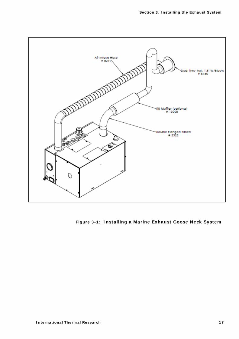
Figure 3-1 shows a standard setup for the exhaust with a gooseneck configuration for sea-going boats. To install the exhaust system:
1 Leave suitable air spacing to protect combustible materials. Use an exhaust collar and metal shields where required.
2 Find an appropriate location for the exhaust of the heater. (See Figure 3-1)
3 Securely screw the exhaust piping to the Hurricane® Zephyr™ HW fitting using approved sealant.
4 Connect the exhaust piping in series with the muffler, using heavy-duty exhaust clamps. If you use vibration isolation mounts they must be rated for high temperature.
5 Connect the flexible air-intake tubing (2” ID) to the air-intake fitting on top of the heater. Use a #32 gear clamp to attach the tubing to this fitting. The other end of the air-intake hose can be installed in the configurations as explained above.
6 Find a suitable location to place the thru hull fitting. It is preferred you use one of the 1.5" dual ITR thru hull fittings. Use a proper clamp to attach the air intake hose and the flexible exhaust tubing to the thru hull/intake fitting. Ensure the run of tubing is as short as possible to facilitate air flow. (See Figure 3-1)
7 Secure both ends of the air-intake tubing with properly sized hose clamps to prevent air leaks.
8 Make sure the air-intake and exhaust hoses are not leaking and are not touching each other.
9 If necessary, protect the air-intake entrance from water and dirt with a guard or shield.
10 Again it is recommended on a sea going yacht, to use a dual thru-hull fitting and make sure it is at least 24 to 30” above the waterline. The exhaust must be goose-necked. (See Figure 3-1)
Section 3, Installing the Exhaust System
International Thermal Research 17
Figure 3-1: Installing a Marine Exhaust Goose Neck System

Section 3, Installing the Exhaust System
18 Installation Manual for Hurricane® Zephyr™ HW Heating System
International Thermal Research 19
Section 1, Installing the Fuel System
4.1 Before You Begin
For efficient and safe operation of the Hurricane® Zephyr™ HW, follow all recommendations for properly installing the fuel system. Any deviations from these recommendations must be approved by Calcutt Boats or ITR.
Although the Hurricane® Zephyr™ HW is compatible with furnace oil, stove oil, Biodiesel 20 and jet fuel, it is only certified for use with diesel #1 and #2. DO NOT USE GASOLINE, CRANKCASE OIL, OR ANY OIL CONTAINING GASOLINE.
Keep fuel lines away from any heat source above 100°F (38°C).
Keep gasoline and any equipment that uses gasoline away from the Hurricane® Zephyr™ HW location. The Hurricane® Zephyr™ HW is not rated for use in a flammable environment.
Never share the fuel supply line of the Hurricane® Zephyr™ HW with any other fuel-burning device.
4.2 Fuel System Installation
The fuel pump in the Hurricane® Zephyr™ HW has a maximum flow capacity of 25 gallon/hr and a maximum flow pressure of 11.5 psi. A 10 micron fuel filter is recommended. Select a fuel filter based on these requirements.
Recommendation for Installation
Section
4
! DANGER
! WARNING
Section 4, Installing the Fuel System
20 Installation Manual for Hurricane® Zephyr™ HW Heating System
The Hurricane® Zephyr™ HW’s fuel connections are accessed from the top of the heater. Both 1/4" hose barb connections are located on the top left of the Zephyr™ and are labelled “inlet” and “return”. The minimum recommended size for the fuel line is 1/4" I.D. The fuel return line should connect to the fuel supply tank
The following are recommended for fuel system installation:
The fuel supply line from the fuel tank to the heater fuel inlet must originate from a dedicated fuel pickup.
• The fuel supply line should be installed with minimal rise from the fuel tank. The total rise from the bottom of the pickup tube to the fuel inlet on the Hurricane® Zephyr™ HW should not exceed 60”. There are no minimum clearance requirements between the fuel tank and the Hurricane® Zephyr™ HW.
The fuel line must be secured throughout its run, to prevent damage from rubbing, chafing and kinking during normal operation.
• All fuel line connection points and hoses must use suitable clamps and must be checked for leaks upon installation. They must also be checked periodically as part of normal maintenance. Constant tension spring clamps are recommended for these connection points.
• A primary, UL and/or CSA approved fuel oil filter (not provided) must be installed on the supply line between the fuel tank and the Hurricane® Zephyr™ HW, in a manner that ensures easy access for maintenance. All filters must be replaced as part of normal maintenance.
• Fuel line hose used must be appropriate for your requirements. It is strongly recommended that the hoses have permanently installed end fittings.
4.3 What NOT to Do
• Don’t allow the fuel or the fuel lines to become contaminated with foreign material.
• Don’t allow the fuel lines to become damaged or constricted.
NOTICE
! CAUTION
Section 4, Installing the Fuel System
International Thermal Research 21
Ensure that fuel lines are always protected from contamination by foreign material. When installing or servicing, seal off ends to prevent contamination. After installing, you may also wish to flush the fuel line to rid it of air and any foreign material.
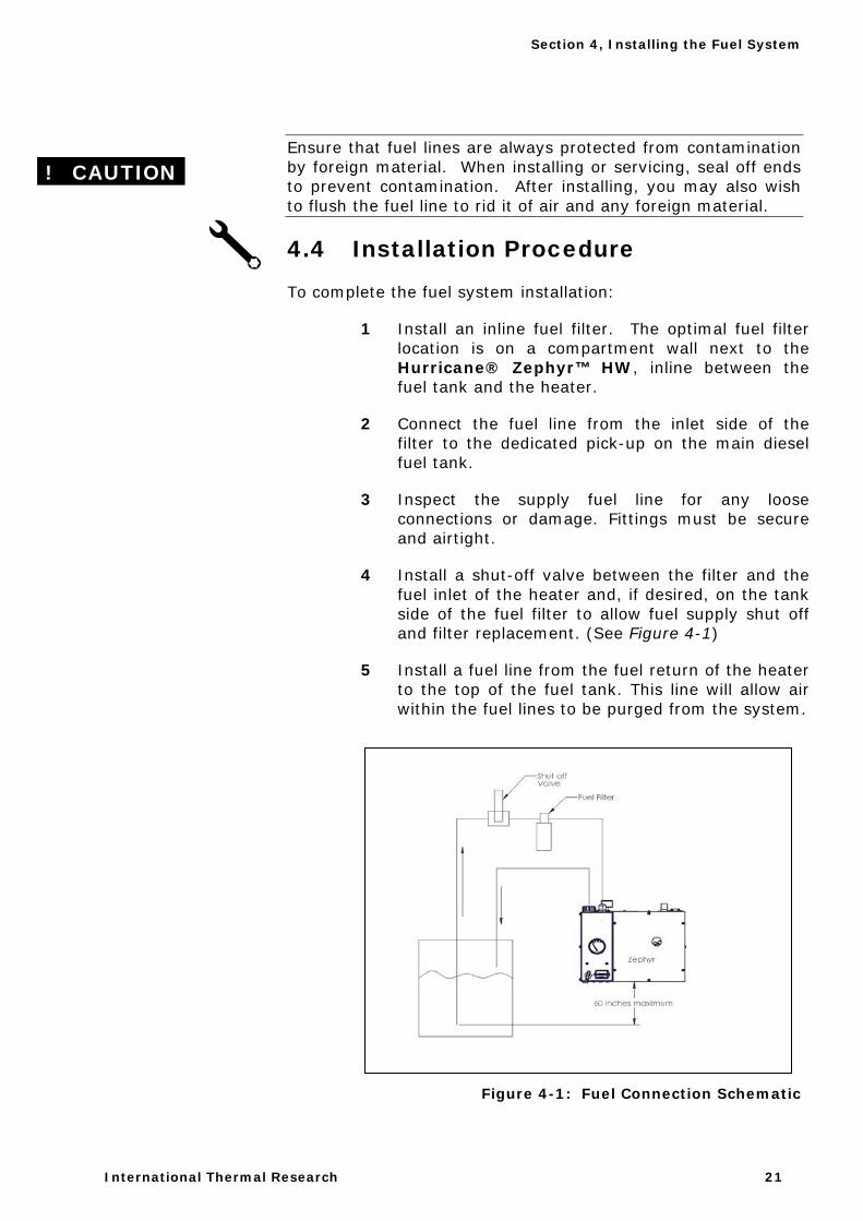
4.4 Installation Procedure
To complete the fuel system installation:
1 Install an inline fuel filter. The optimal fuel filterlocation is on a compartment wall next to theHurricane® Zephyr™ HW, inline between the fuel tank and the heater.
2 Connect the fuel line from the inlet side of thefilter to the dedicated pick-up on the main dieselfuel tank.
3 Inspect the supply fuel line for any looseconnections or damage. Fittings must be secureand airtight.
4 Install a shut-off valve between the filter and the fuel inlet of the heater and, if desired, on the tank side of the fuel filter to allow fuel supply shut offand filter replacement. (See Figure 4-1)
5 Install a fuel line from the fuel return of the heaterto the top of the fuel tank. This line will allow airwithin the fuel lines to be purged from the system.
Figure 4-1: Fuel Connection Schematic
! CAUTION

Section 4, Installing the Fuel System
22 Installation Manual for Hurricane® Zephyr™ HW Heating System
International Thermal Research 23
Section 5, Installing Cabin Fans
5.1 Before You Begin
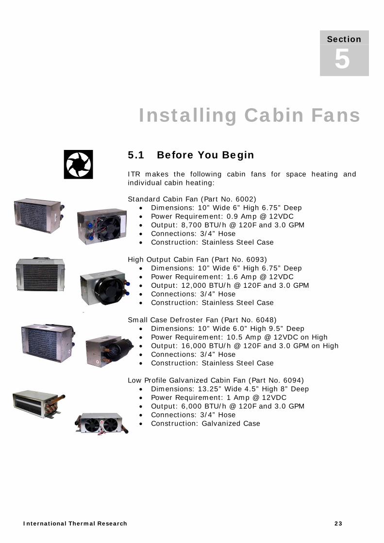
ITR makes the following cabin fans for space heating and individual cabin heating:
Standard Cabin Fan (Part No. 6002) • Dimensions: 10” Wide 6” High 6.75” Deep • Power Requirement: 0.9 Amp @ 12VDC • Output: 8,700 BTU/h @ 120F and 3.0 GPM • Connections: 3/4” Hose • Construction: Stainless Steel Case
High Output Cabin Fan (Part No. 6093)
• Dimensions: 10” Wide 6” High 6.75” Deep • Power Requirement: 1.6 Amp @ 12VDC • Output: 12,000 BTU/h @ 120F and 3.0 GPM • Connections: 3/4” Hose • Construction: Stainless Steel Case
Small Case Defroster Fan (Part No. 6048)
• Dimensions: 10” Wide 6.0” High 9.5” Deep • Power Requirement: 10.5 Amp @ 12VDC on High • Output: 16,000 BTU/h @ 120F and 3.0 GPM on High • Connections: 3/4” Hose • Construction: Stainless Steel Case
Low Profile Galvanized Cabin Fan (Part No. 6094)
• Dimensions: 13.25” Wide 4.5” High 8” Deep • Power Requirement: 1 Amp @ 12VDC • Output: 6,000 BTU/h @ 120F and 3.0 GPM • Connections: 3/4” Hose • Construction: Galvanized Case
Section
5
Section 5, Installing Cabin Fans
24 Installation Manual for Hurricane® Zephyr™ HW Heating System
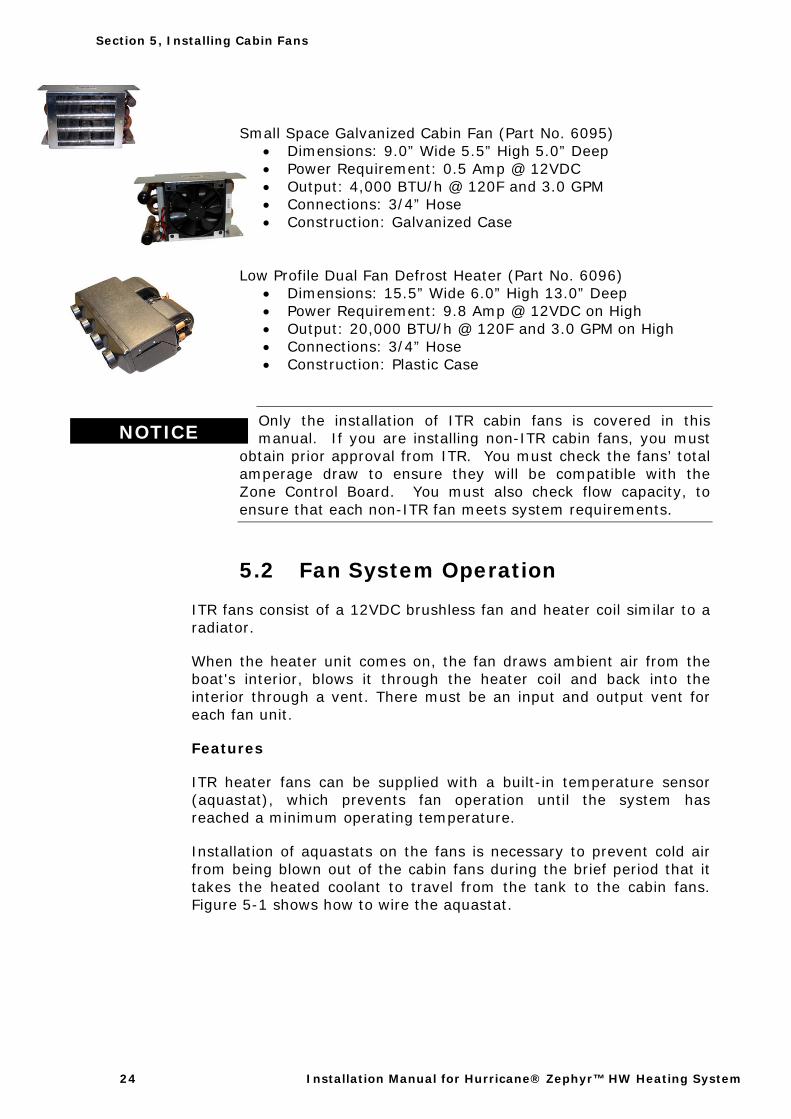
Small Space Galvanized Cabin Fan (Part No. 6095) • Dimensions: 9.0” Wide 5.5” High 5.0” Deep • Power Requirement: 0.5 Amp @ 12VDC • Output: 4,000 BTU/h @ 120F and 3.0 GPM • Connections: 3/4” Hose • Construction: Galvanized Case
Low Profile Dual Fan Defrost Heater (Part No. 6096)
• Dimensions: 15.5” Wide 6.0” High 13.0” Deep • Power Requirement: 9.8 Amp @ 12VDC on High • Output: 20,000 BTU/h @ 120F and 3.0 GPM on High • Connections: 3/4” Hose • Construction: Plastic Case
Only the installation of ITR cabin fans is covered in this manual. If you are installing non-ITR cabin fans, you must
obtain prior approval from ITR. You must check the fans’ total amperage draw to ensure they will be compatible with the Zone Control Board. You must also check flow capacity, to ensure that each non-ITR fan meets system requirements.
5.2 Fan System Operation
ITR fans consist of a 12VDC brushless fan and heater coil similar to a radiator.
When the heater unit comes on, the fan draws ambient air from the boat's interior, blows it through the heater coil and back into the interior through a vent. There must be an input and output vent for each fan unit.
Features
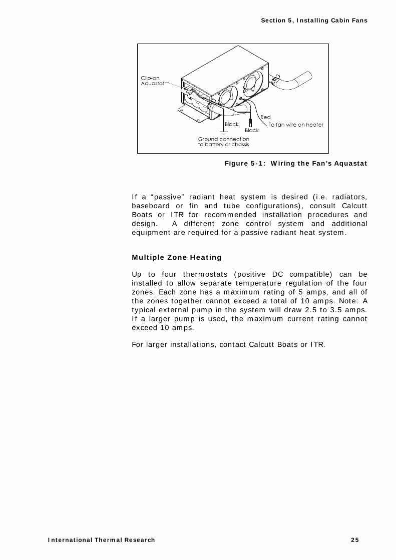
ITR heater fans can be supplied with a built-in temperature sensor (aquastat), which prevents fan operation until the system has reached a minimum operating temperature.
Installation of aquastats on the fans is necessary to prevent cold air from being blown out of the cabin fans during the brief period that it takes the heated coolant to travel from the tank to the cabin fans. Figure 5-1 shows how to wire the aquastat.
NOTICE
Section 5, Installing Cabin Fans
International Thermal Research 25
Figure 5-1: Wiring the Fan’s Aquastat
If a “passive” radiant heat system is desired (i.e. radiators, baseboard or fin and tube configurations), consult Calcutt Boats or ITR for recommended installation procedures and design. A different zone control system and additional equipment are required for a passive radiant heat system.
Multiple Zone Heating
Up to four thermostats (positive DC compatible) can be installed to allow separate temperature regulation of the four zones. Each zone has a maximum rating of 5 amps, and all of the zones together cannot exceed a total of 10 amps. Note: A typical external pump in the system will draw 2.5 to 3.5 amps. If a larger pump is used, the maximum current rating cannot exceed 10 amps.
For larger installations, contact Calcutt Boats or ITR.
Section 5, Installing Cabin Fans
26 Installation Manual for Hurricane® Zephyr™ HW Heating System
Accessories and Components Needed
ITR supplies a variety of accessories that can be introduced to the system during installation. These can be purchased separately as needed. Some of the most commonly used items are:
• Thermostats — installed in the boat's interior for each individual heating zone (up to 4 for the Hurricane® Zephyr™ HW).
• Air Outlet Vents — covers that are installed flush to an interior wall.
• Fan Guards — to protect the fan blades from damage. Recommended for fans installed in storage areas or other accessible areas where something could contact the fans.
• Two-Speed Fan Switches – to allow low and high-speed setting control from inside the yacht. For use with a variety of ITR cabin fans.
• Three-Speed Fan Switches — to enable low, medium and high-speed settings from inside the pilot house. For use with ITR defrost heaters.
• Air Ducting — to allow installation of fans in remote locations (i.e. not directly adjacent to the interior space to be heated). Heated air is ducted to output locations.
• Air outlet plates - to allow ducting for one, two or three separate outlets (e.g. use one fan to heat two different areas by installing a dual air outlet plate).

Section 5, Installing Cabin Fans
International Thermal Research 27
5.3 What NOT to Do
• Don’t install fans that require more BTUs than the Hurricane® Zephyr™ HW can produce, or the system will not operate effectively.
• Don’t mount the return air outlet too close to the fan’s air intake source.
5.4 Mounting Locations
Carefully choose the mounting locations of your fans:
• Locate the fans to evenly heat the desired area.
• Provisions must be made to protect water lines from freezing.
• Install fans at floor level or very near floor level, in order to optimize circulation.
• Allow a minimum 16 square inch (100 cm sq.) opening in the fan heaters’ mounting compartment to allow sufficient intake of air.
ITR’s cabin heater fans can be mounted on the floor or on the wall, either flat or on their side.
The thermostat(s) should be mounted on an interior wall or bulkhead, away from windows, heater vents, and cabin fan heaters. This will avoid an inaccurate reading of the actual zone temperature.
Section 5, Installing Cabin Fans
28 Installation Manual for Hurricane® Zephyr™ HW Heating System
5.5 Installation Procedure
After choosing the appropriate mounting locations and configurations:
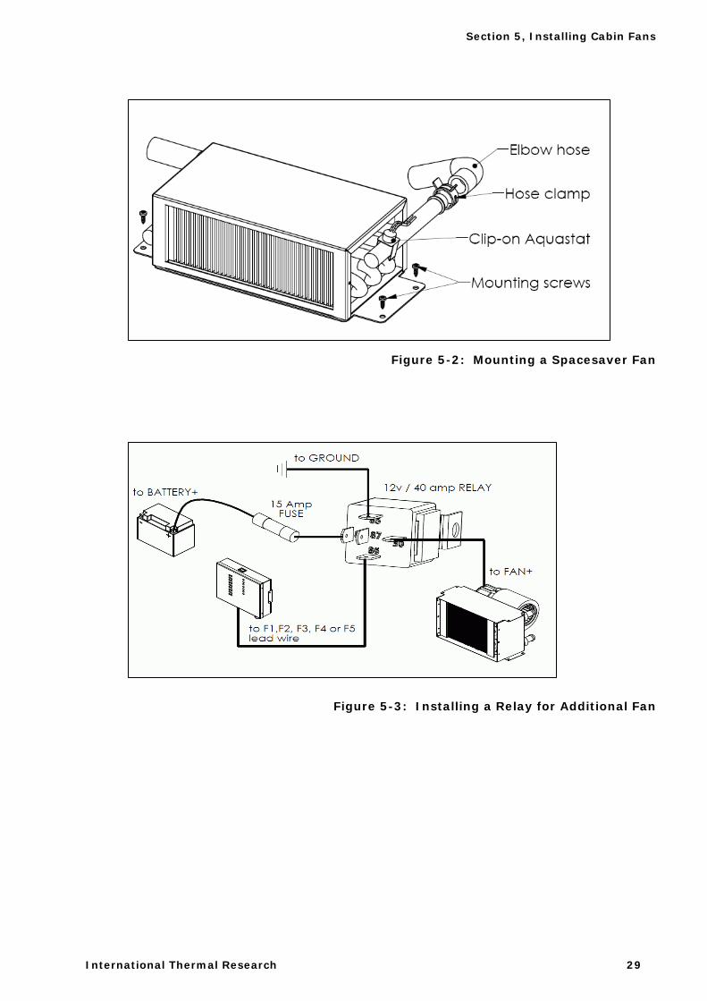
1 Mount the fan using appropriate sheet metal screws or wood screws. (See Figure 5-2.)
2 If you are using ducting and a dual air outlet plate for any fan, limit the total length of duct for both outlets to 36” for optimum air output.
3 Select the appropriate mounting location for the thermostat(s), as well as any fan speed switches. See Section 6- Electrical Systems for wiring thermostats to the Zephyr™ control board.
4 The Zephyr™ zone board allows a cumulative draw of 18 amps, including external pumps. If an individual cabin fan draw is larger than the 5 amp limit, you must install a separate relay to power the fan. This relay will use the existing fan circuit as a signal and must be wired to a secondary power source (fused from the positive battery terminal), and not from the power to the heater’s control board. (See Figure 5-3.)
5 To install plumbing lines to the fans, see Section 7 – Plumbing the System.
Section 5, Installing Cabin Fans
International Thermal Research 29
Figure 5-2: Mounting a Spacesaver Fan
Figure 5-3: Installing a Relay for Additional Fan

Section 5, Installing Cabin Fans
30 Installation Manual for Hurricane® Zephyr™ HW Heating System

International Thermal Research 31
Section 5, Wiring the Electrical System
6.1 Before You Begin
The heater and its electrical control board are pre-wired and have been thoroughly tested together as a unit.
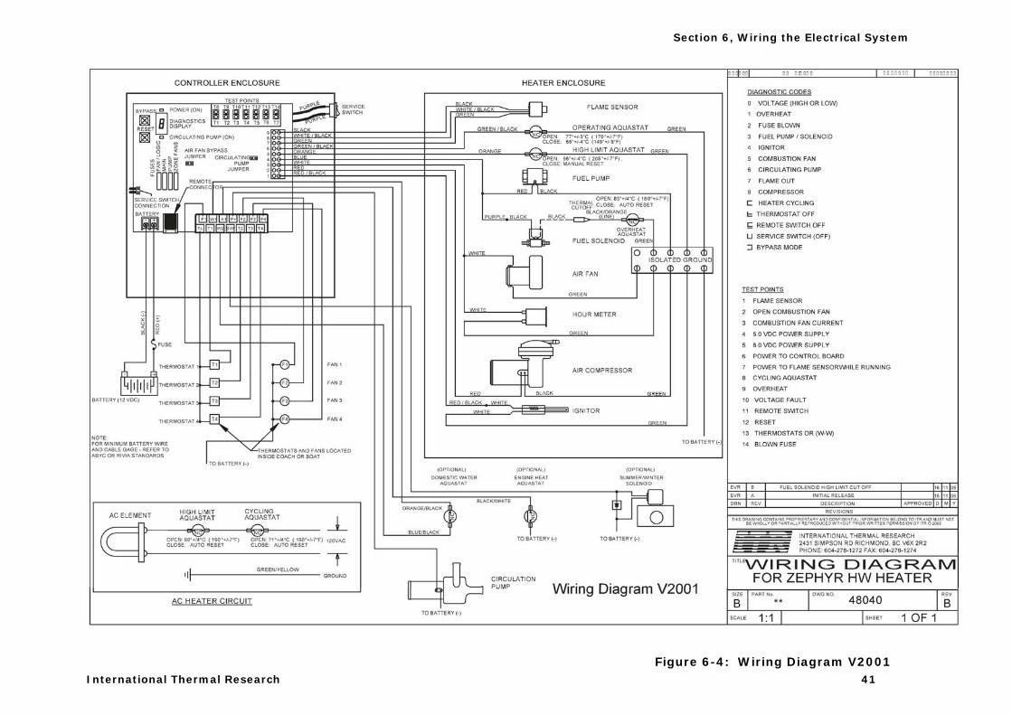
To review the wiring system for the entire heating system, refer to the schematic at the end of this section (Figure 6-4).
All electrical connections and wiring must comply with normally-accepted 12 VDC and 120VAC (North America)/240 VAC (Europe) wiring practices, local regulations, and ABYC /RVIA standards. Only a qualified electrical installer should complete the wiring. All field wiring is to be in accordance with CSA Standard C22.1, Canadian Electrical Code Part I or the National Electric Code.
6.2 Electrical Noise
Electrical noise is an unwanted electrical signal which produces undesirable effects in the circuits of the control system.
Most electronic noise stems from crude wiring practices, which allow "coupling" (the transfer of electrical noise into the control circuit from the noise source). Erratic, intermittent, and inconsistent system behaviour often suggests electrical signal interference, and can be difficult to diagnose. Lower power level controllers that use electronic logic, especially those using integrated circuits, are especially sensitive to electronic noise.
A typical electronic noise source is any piece of equipment that can cause changes in voltage or current when turned ON and OFF. A single side-band transmitter is an example of this type of equipment.
Common electronic noise sources:
Section
6
! WARNING
Section 6, Wiring the Electrical System
32 Installation Manual for Hurricane® Zephyr™ HW Heating System
• Loose connections • Switches and relay contacts operating inductive loads, such as
motors, coils, solenoids, and relays etc. • Welding machinery • Heavy current carrying conductors • Fluorescent and neon lights
Sensor input and power output lines, as well as the power source line, all have the potential to couple the control circuit to a noise source.
"Common Impedance Coupling" occurs when two circuits share a common conductor. Avoid running multiple loads or return lines on one conductor. Use independent leads for each return circuit, and terminate all return circuits at the same physical point.
"Magnetic (Inductive) Coupling" generally appears when there are wires running parallel, or in close vicinity to, each other. This is especially prevalent when the wires from several circuits are bundled together in order to make the system wiring appear neat.
"Electrostatic (Capacitive) Coupling" is a function of the distance wires run parallel with each other, the distance between the wires, and the diameter of the wire. The best way to eliminate Electrostatic Capacitive Coupling is to run separate leads from separate circuits in separate bundles, taking special care to keep AC (high power lead) wires separated from DC (low power level) wires. If possible, twisted lead pairs and shielded cables should be used. Note: special attention should be given to AC power lines, because they are a source of unusual types of noise-related problems in control circuits.
"Electromagnetic (Radiation) Coupling" occurs when the control circuit is very close to a high-energy source that is capable of magnetic or electrostatic induction of a voltage. A common source of such radiation is an inverter, alternator, generator, motor transformers, fluorescent lights, radio, TV, and navigation equipment.
Section 6, Wiring the Electrical System
International Thermal Research 33
6.3 12 VDC
The following apply to the 12VDC power supplied to the heater:
• There is one electrical terminal on the main control board for the primary 12VDC positive and negative (black) power. There are no direct 12VDC power connections to the heater itself.
Primary DC power should originate from a dedicated connection on the house battery bank. A 25 amp fuse or breaker must be included inline from the battery to the positive connection on the control board. The primary power wire gauge must be sized to permit no more than a 3% voltage drop from the battery to the heater.
• There are no switches on the control board or box that disconnects the power to the heater and/or control board once 12 VDC power has been supplied to the board.
• A properly shielded power system is required for safe, trouble-free operation.
6.4 120/240 VAC
• The Hurricane® Zephyr™ HW is equipped with one 1500 Watt 120 VAC (North America) electric heating element or one 1500 Watt 240 VAC (Europe) electric heating element (optional). The connections for the electrical supply are on the top right side of the heater, under a cover.
• The power wires for the heating elements are three 14 gauge stranded copper leads that use standard AC color code (black – hot, white – neutral, green/yellow – ground). They are to be connected using standard 120/240 VAC electrical connectors and terminals. The wires are to be connected to a switch, and from there to a separate AC circuit breaker. Once the connection is completed, the wires are to be inserted back into their compartment and the cover secured.
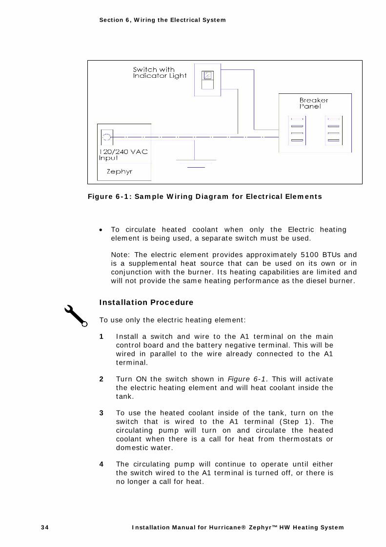
• The electrical heating element is operated independently from the control board. It is best to wire the element to a separate switch with indicator light to see when the element is activated. (See Figure 6-1).
! WARNING
Section 6, Wiring the Electrical System
34 Installation Manual for Hurricane® Zephyr™ HW Heating System
Figure 6-1: Sample Wiring Diagram for Electrical Elements
• To circulate heated coolant when only the Electric heating element is being used, a separate switch must be used.
Note: The electric element provides approximately 5100 BTUs and is a supplemental heat source that can be used on its own or in conjunction with the burner. Its heating capabilities are limited and will not provide the same heating performance as the diesel burner.
Installation Procedure
To use only the electric heating element:
1 Install a switch and wire to the A1 terminal on the main control board and the battery negative terminal. This will be wired in parallel to the wire already connected to the A1 terminal.
2 Turn ON the switch shown in Figure 6-1. This will activate the electric heating element and will heat coolant inside the tank.
3 To use the heated coolant inside of the tank, turn on the switch that is wired to the A1 terminal (Step 1). The circulating pump will turn on and circulate the heated coolant when there is a call for heat from thermostats or domestic water.
4 The circulating pump will continue to operate until either the switch wired to the A1 terminal is turned off, or there is no longer a call for heat.
Section 6, Wiring the Electrical System
International Thermal Research 35
During installation or servicing, or if coolant is low, do not operate the electric element until coolant is added to the heater and all trapped air has been removed from the system.
6.5 Electrical Components
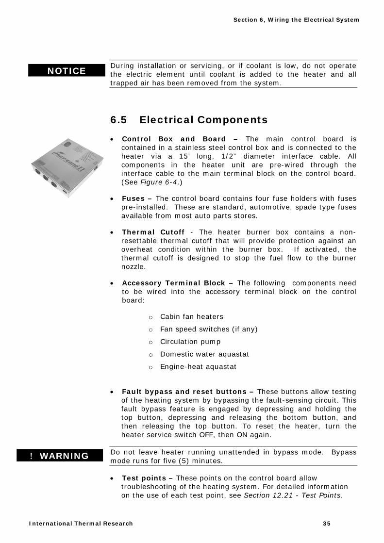
• Control Box and Board – The main control board is contained in a stainless steel control box and is connected to the heater via a 15’ long, 1/2” diameter interface cable. All components in the heater unit are pre-wired through the interface cable to the main terminal block on the control board. (See Figure 6-4.)
• Fuses – The control board contains four fuse holders with fuses pre-installed. These are standard, automotive, spade type fuses available from most auto parts stores.
• Thermal Cutoff - The heater burner box contains a non-resettable thermal cutoff that will provide protection against an overheat condition within the burner box. If activated, the thermal cutoff is designed to stop the fuel flow to the burner nozzle.
• Accessory Terminal Block – The following components need to be wired into the accessory terminal block on the control board:
o Cabin fan heaters
o Fan speed switches (if any)
o Circulation pump
o Domestic water aquastat
o Engine-heat aquastat
• Fault bypass and reset buttons – These buttons allow testing of the heating system by bypassing the fault-sensing circuit. This fault bypass feature is engaged by depressing and holding the top button, depressing and releasing the bottom button, and then releasing the top button. To reset the heater, turn the heater service switch OFF, then ON again.
Do not leave heater running unattended in bypass mode. Bypass mode runs for five (5) minutes.
• Test points – These points on the control board allow troubleshooting of the heating system. For detailed information on the use of each test point, see Section 12.21 - Test Points.
NOTICE
! WARNING
Section 6, Wiring the Electrical System
36 Installation Manual for Hurricane® Zephyr™ HW Heating System
• Diagnostic Display – An LED indicator for diagnostics of the heater. It also has signal lights for heater power and the circulating pump.
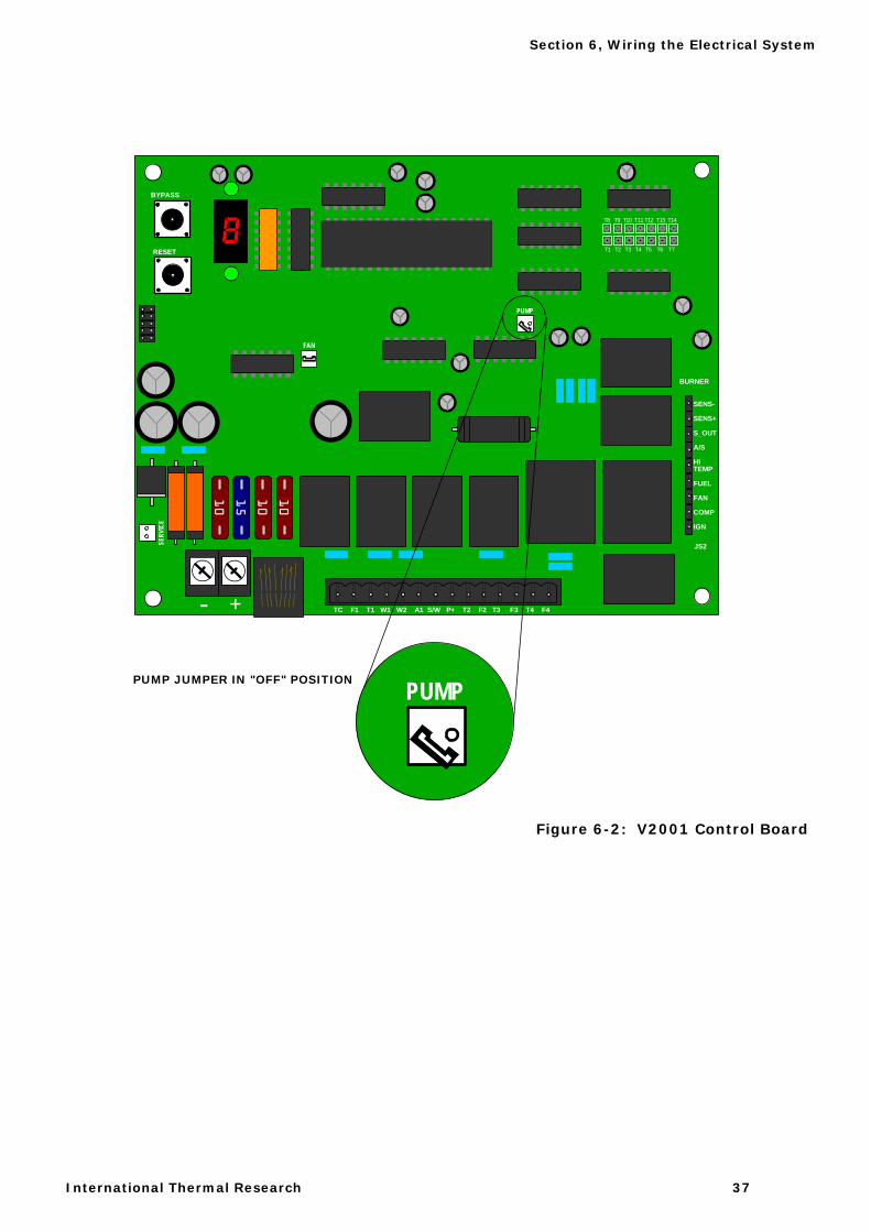
• Circulating pump jumper – This jumper on the control board allows you to run the circulating pump and test the system circulation without turning the heater on.
• Battery connector – Connection points for the positive and negative power from the house battery to the heater.
• Remote connector – Connection point for the cable from the remote LCD panel.
• Service switch – The service switch allows full operation (service switch ON) or partial operation (service switch OFF) of the heater control board. In the OFF position, it will only allow the circulating pump and cabin fan to run in response to both a call for heat from the thermostat or domestic water aquastat, and the presence of an alternate heat source (engine or electric heating element) supplying adequate heat to the system. The operating circuitry of the burner in the heater itself is non-functional. In the ON position, all operations and features of the heater and control board are functional. In normal operation, the service switch is left ON. NOTE: The service switch has an additional short circuit fault (#3–4–5–6–8) reset function. This is performed by turning the service switch OFF, then ON.
• Hour meter – Located on the front of the heater unit, the hour meter counts the accumulated operating hours for the heater.
• Remote LCD panel – This panel enables the diesel burner and allows operational control and fault reset from inside the boat. The panel also provides diagnostic information and a fault history. The panel connects to the control board via a supplied 25ft/7.6m RJ11 cable. A 50ft/15.2m cable is available as an option.
Section 6, Wiring the Electrical System
International Thermal Research 37
8
10
15
10
- +
SERV
ICE
PUMP
FAN
T1 T2 T3 T4 T5 T6 T7
T8 T9 T10 T11 T12 T13 T14
SENS-
SENS+
S_OUT
A/S
HITEMP
FUEL
FAN
COMP
IGN
BURNER
JS2
BYPASS
RESET
TC F1 T1 W1 W2 A1 S/W P+ T2 F2 T3 F3 T4 F4
PUMP
10
PUMP JUMPER IN "OFF" POSITION
Figure 6-2: V2001 Control Board
Section 6, Wiring the Electrical System
38 Installation Manual for Hurricane® Zephyr™ HW Heating System
6.6 What NOT to Do
Never shut off the heater power via an inline battery or master switch while the system is running. Never disconnect the battery when the heater is running, and never disconnect the battery while the inverter is charging.
Doing either will severely damage the heater because it fails to automatically purge the combustion chamber. Such damage is detectable upon inspection and will not be covered under warranty. Always shut the system off using the normal system controls, after it has completed its purge.
When running in bypass mode, never leave the heater unattended.
6.7 Procedure
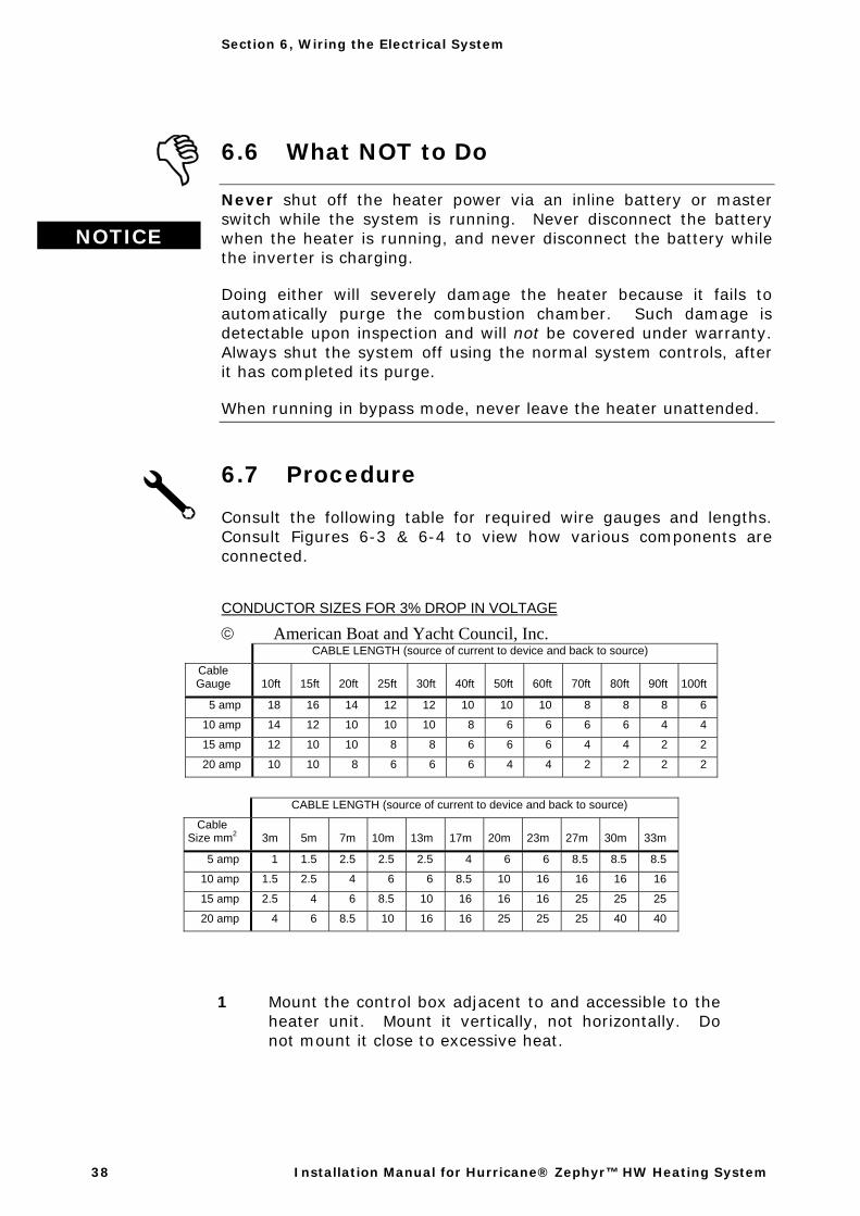
Consult the following table for required wire gauges and lengths. Consult Figures 6-3 & 6-4 to view how various components are connected.
CONDUCTOR SIZES FOR 3% DROP IN VOLTAGE
© American Boat and Yacht Council, Inc. CABLE LENGTH (source of current to device and back to source)
Cable Gauge 10ft 15ft 20ft 25ft 30ft 40ft 50ft 60ft 70ft 80ft 90ft 100ft
5 amp 18 16 14 12 12 10 10 10 8 8 8 6
10 amp 14 12 10 10 10 8 6 6 6 6 4 4
15 amp 12 10 10 8 8 6 6 6 4 4 2 2
20 amp 10 10 8 6 6 6 4 4 2 2 2 2
CABLE LENGTH (source of current to device and back to source)
Cable Size mm2 3m 5m 7m 10m 13m 17m 20m 23m 27m 30m 33m
5 amp 1 1.5 2.5 2.5 2.5 4 6 6 8.5 8.5 8.5
10 amp 1.5 2.5 4 6 6 8.5 10 16 16 16 16
15 amp 2.5 4 6 8.5 10 16 16 16 25 25 25
20 amp 4 6 8.5 10 16 16 25 25 25 40 40
1 Mount the control box adjacent to and accessible to the heater unit. Mount it vertically, not horizontally. Do not mount it close to excessive heat.
NOTICE
Section 6, Wiring the Electrical System
International Thermal Research 39
2 Wire the positive terminal of the house battery through a 25 amp, heavy-duty rated fuse (using #10 gauge wire) to the positive terminal on the control board inside the main control box. Wire the negative terminal of the house battery to the negative terminal of the control board.
3 Using the recommended wire gauges, prepare all wire terminations for approved connections from the control board to each of the fan heaters and thermostats (and any optional switches).
4 Wire the fan heaters to the terminals in the control board using #16 wire (minimum) and a #8 fork connection on each fan. See Figure 6-4. There are four terminals, F1 to F4, corresponding to the four zones.
5 Connect the fan grounds to the negative terminal of the battery or to an adjacent chassis ground location.
6 Wire the thermostats for the fan heaters to the terminals in the control board using #18 gauge wire (minimum) and a single #8 fork connection. See Figure 6-4 for the correct terminals (T1 to T4, and T-C common).
7 If domestic water heating, engine waste heat, or summer/winter loop functions of the heater are required, see Section 9 - Domestic Hot Water Heating and Section 10 - Engine Heat Management for details.
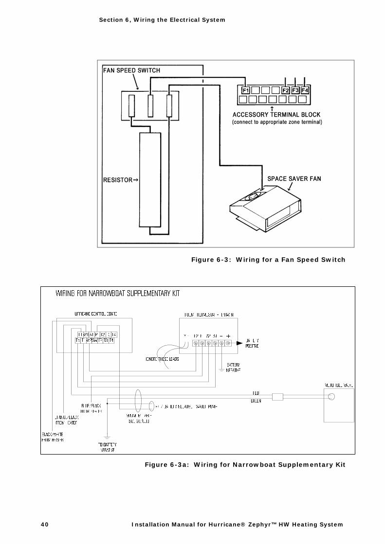
8 Install the switch between the fan circuit and the positive DC fan connection using #16 wire (minimum) and a #8 fork connection. See Figure 6-3 for a switch wiring diagram.
9 Mount the remote panel in the living areas where it can be easily accessed. Any accessory switches should be mounted adjacent to the remote panel for ease of use.
10 Connect the remote cable from the control board to the remote panel.
11 Ensure that all pre-wired connections between the heater and control box are secure.
Section 6, Wiring the Electrical System
40 Installation Manual for Hurricane® Zephyr™ HW Heating System
Figure 6-3: Wiring for a Fan Speed Switch
Figure 6-3a: Wiring for Narrowboat Supplementary Kit
Section 6, Wiring the Electrical System
International Thermal Research 41
Figure 6-4: Wiring Diagram V2001

42 Installation Manual for Hurricane® Zephyr™ HW Heating System
International Thermal Research 43
Section 7, Plumbing the System
7.1 Before You Begin
For an efficient heating system, you must:
• Install a pump with enough capacity to provide sufficient coolant flow to all components in the system.
• Install the appropriate number of cabin fans for the space to be heated.
• Minimize heat loss from coolant tubes and hoses. • Eliminate any air within the system.
Installing too many cabin fans may reduce the efficiency of the individual fans, resulting in less overall heat output. Without adequate flow to the cabin fans downstream, fans located directly after the heater can starve a system.
7.2 Plumbing Components
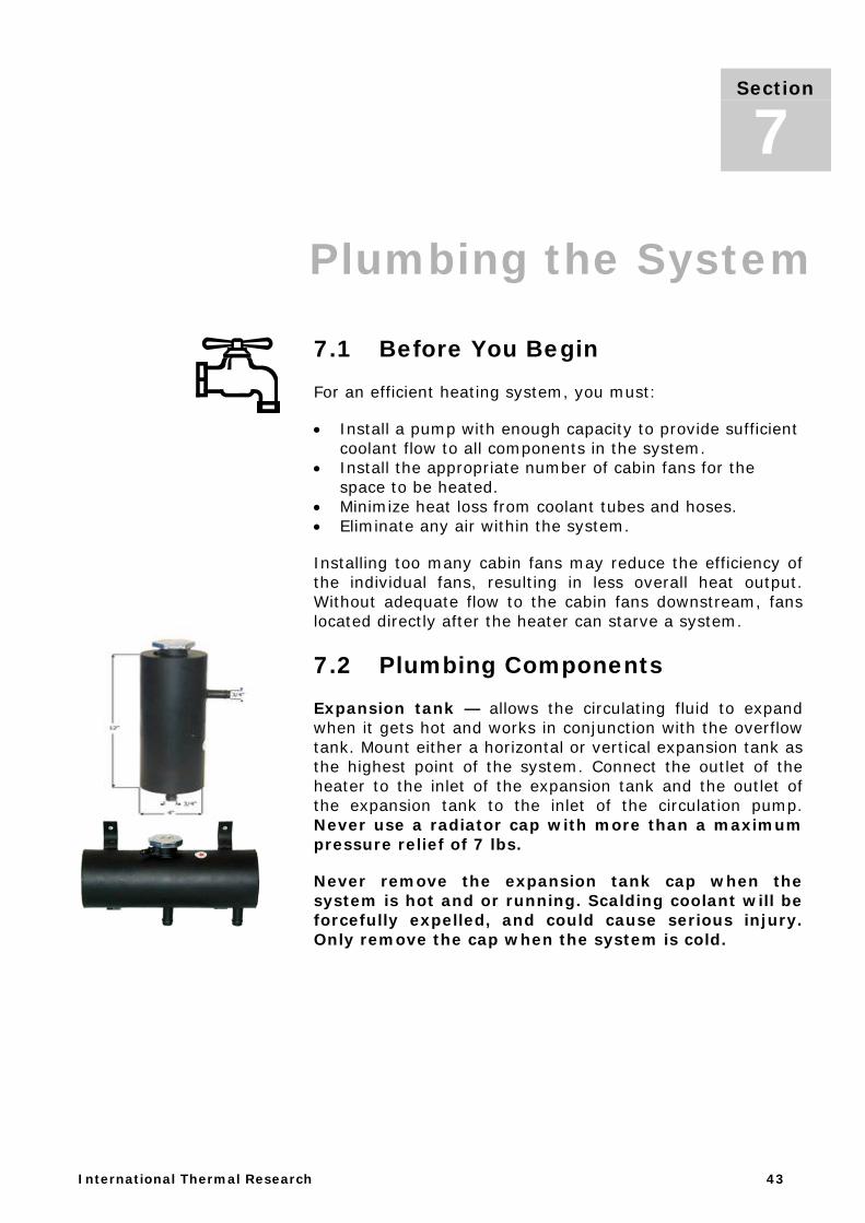
Expansion tank — allows the circulating fluid to expand when it gets hot and works in conjunction with the overflow tank. Mount either a horizontal or vertical expansion tank as the highest point of the system. Connect the outlet of the heater to the inlet of the expansion tank and the outlet of the expansion tank to the inlet of the circulation pump. Never use a radiator cap with more than a maximum pressure relief of 7 lbs.
Never remove the expansion tank cap when the system is hot and or running. Scalding coolant will be forcefully expelled, and could cause serious injury. Only remove the cap when the system is cold.
Section
7
Section 7, Plumbing the System
44 Installation Manual for Hurricane® Zephyr™ HW Heating System
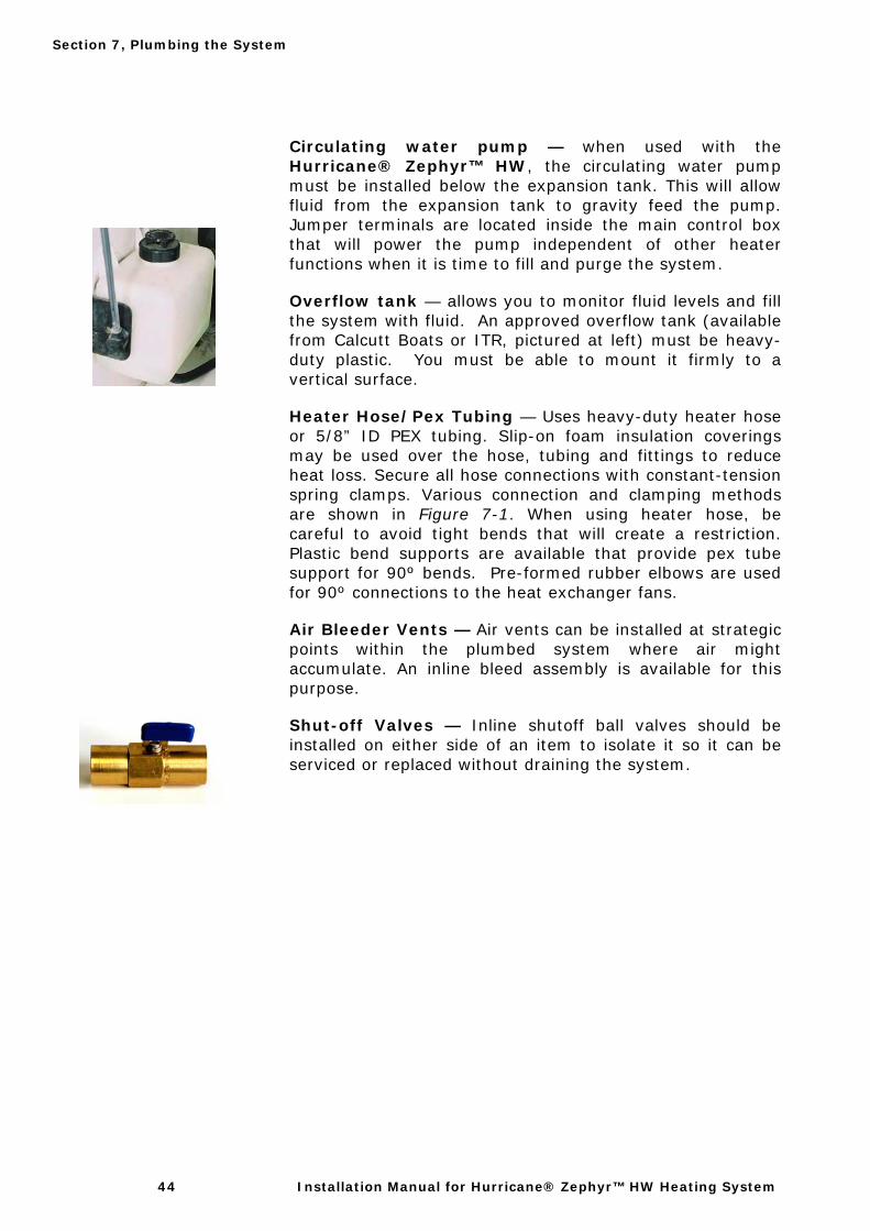
Circulating water pump — when used with the Hurricane® Zephyr™ HW, the circulating water pump must be installed below the expansion tank. This will allow fluid from the expansion tank to gravity feed the pump. Jumper terminals are located inside the main control box that will power the pump independent of other heater functions when it is time to fill and purge the system.
Overflow tank — allows you to monitor fluid levels and fill the system with fluid. An approved overflow tank (available from Calcutt Boats or ITR, pictured at left) must be heavy-duty plastic. You must be able to mount it firmly to a vertical surface.
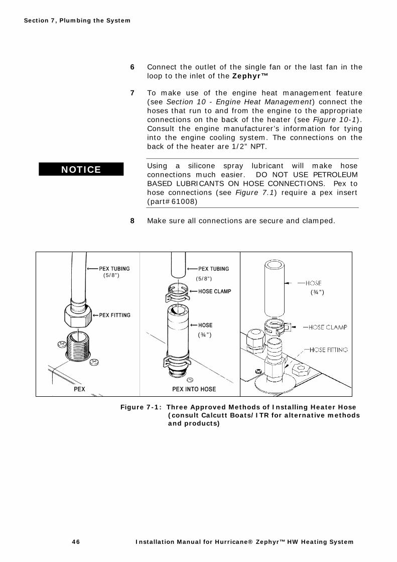
Heater Hose/Pex Tubing — Uses heavy-duty heater hose or 5/8” ID PEX tubing. Slip-on foam insulation coverings may be used over the hose, tubing and fittings to reduce heat loss. Secure all hose connections with constant-tension spring clamps. Various connection and clamping methods are shown in Figure 7-1. When using heater hose, be careful to avoid tight bends that will create a restriction. Plastic bend supports are available that provide pex tube support for 90º bends. Pre-formed rubber elbows are used for 90º connections to the heat exchanger fans.
Air Bleeder Vents — Air vents can be installed at strategic points within the plumbed system where air might accumulate. An inline bleed assembly is available for this purpose.
Shut-off Valves — Inline shutoff ball valves should be installed on either side of an item to isolate it so it can be serviced or replaced without draining the system.

Section 7, Plumbing the System
International Thermal Research 45
7.3 What NOT to Do
The heating system’s circulating water pump is the most critical part of the heating system. Never let the pump run dry or you will damage the impeller. This is not covered under warranty.
Don’t use low-quality heater hose.
Don’t let the hose come into contact with solvents, which may cause it to soften and swell. If there is any risk that solvents may contact the hose, insert it into PVC plastic tubing for protection.
7.4 Installation Procedure
To install and connect the plumbing components and heater hose see Figure 1-2 and Figure 7-2 for typical plumbing lay-out diagrams.
1 Mount the overflow tank adjacent to the expansion tank at about the same level, in a location that allows fluid to be added to it easily.
2 Connect the overflow tank to the expansion tank inlet fitting using a clear plastic 3/8” hose. Secure both connections with a clamp.
3 While referring to Figure 7-2, connect the outlet of the heater to the inlet (top) of the expansion tank. Connect the outlet of the expansion tank to the inlet of the circulation pump. Use constant-tension spring clamps on all hose connections. A reducer and a short piece of 1/2” hose is needed to connect the 3/4” hose to the 1/2” connections on the circulation pump.
4 Lay out the heater hose horizontally through the boat, and connect the fan(s) in a series loop. Keep high points to a minimum.
5 Ensure there are no kinks or sharp bends that might restrict the coolant flow. For PEX tubing bends, fit the tubing into a plastic bend support (available for 5/8” and 3/4” tubing). Standard heater hose does not require bend supports but do not bend the hose to the point of collapsing.
NOTICE
Section 7, Plumbing the System
46 Installation Manual for Hurricane® Zephyr™ HW Heating System
6 Connect the outlet of the single fan or the last fan in the loop to the inlet of the Zephyr™
7 To make use of the engine heat management feature (see Section 10 - Engine Heat Management) connect the hoses that run to and from the engine to the appropriate connections on the back of the heater (see Figure 10-1). Consult the engine manufacturer’s information for tying into the engine cooling system. The connections on the back of the heater are 1/2” NPT.
NOTICE Using a silicone spray lubricant will make hose
connections much easier. DO NOT USE PETROLEUM BASED LUBRICANTS ON HOSE CONNECTIONS. Pex to hose connections (see Figure 7.1) require a pex insert (part#61008)
8 Make sure all connections are secure and clamped.
Figure 7-1: Three Approved Methods of Installing Heater Hose (consult Calcutt Boats/ITR for alternative methods
and products)
(5/8”)
(¾”)
(¾”)
(5/8”)
Section 7, Plumbing the System
International Thermal Research 47
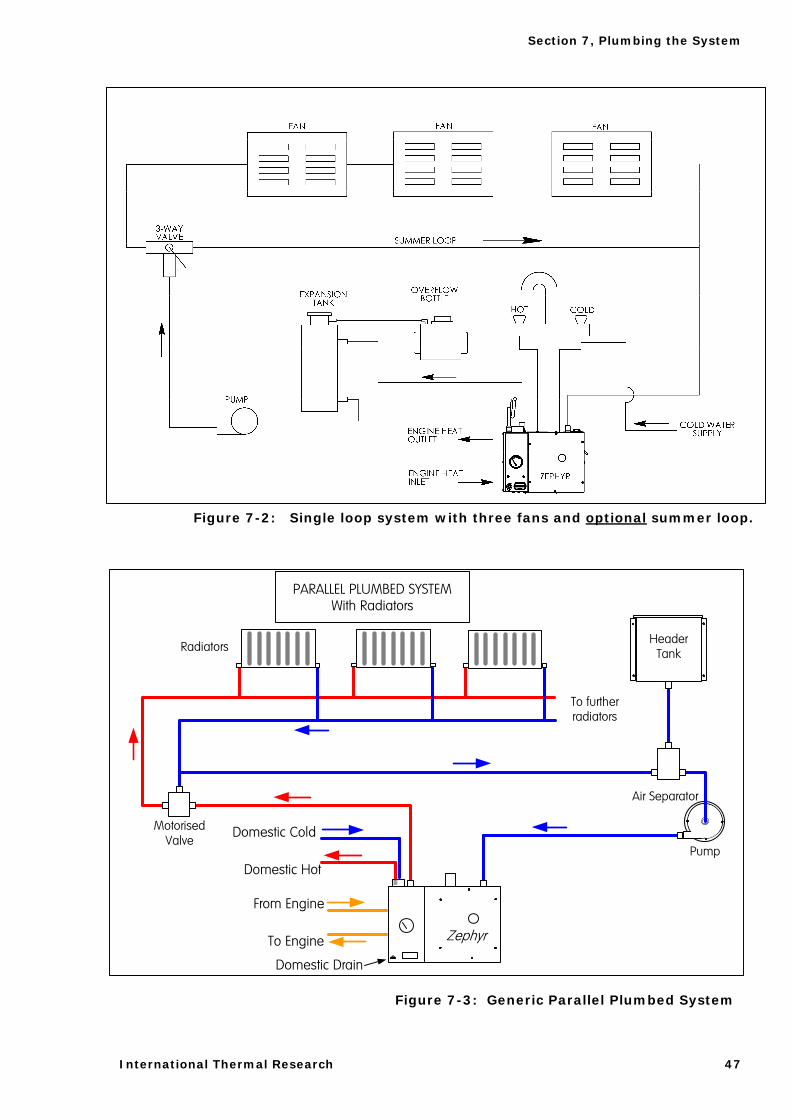
Figure 7-2: Single loop system with three fans and optional summer loop.
Figure 7-3: Generic Parallel Plumbed System
Zephyr
PARALLEL PLUMBED SYSTEMWith Radiators
Air Separator
Motorised Valve
To further radiators
Header Tank
Pump
Radiators
From Engine
To Engine
Domestic Cold
Domestic Hot
Domestic Drain

Section 7, Plumbing the System
48 Installation Manual for Hurricane® Zephyr™ HW Heating System
International Thermal Research 49
Section 8, Filling and Testing the Circulation System
8.1 Before You Begin
After the heating system has been installed, you are ready to fill the system with fluid for purging and testing purposes.
There are two recommended ways you can fill the heating system with fluid and purge it of air at the same time:
• Through the expansion tank • Through a priming manifold
These methods are described below. They are very similar, but the manifold method provides a permanent, built-in mechanism for filling and purging. When using the manifold, you will need a separate self-priming pressure pump (30 – 40 PSI).
After the first 50 hours of operation, yacht movement may cause air bubbles to be dislodged. Monitor fluid levels carefully and add fluid if necessary.
8.2 What NOT To Do
Don’t forget to remove the circulating pump jumper (see Figure 6-4) and store it on a single jumper pin after filling and purging. Otherwise, the pump will run continuously.
Do not attempt to purge the system without installing an expansion tank in the system. Do not bypass the expansion tank when purging the system. Failure to install the expansion tank or bypassing the expansion tank prior to purging the system will result in permanent damage to the heater.
Section
8
TIP If you fill the system with a 50/50 mix of antifreeze and water, this may save you from having to drain and refill the system.
However, if you are unsure of the installation, it’s better to fill and test the system with water first.
Section 8, Filling and Testing the Circulation System
50 Installation Manual for Hurricane® Zephyr™ HW Heating System
Although the system can operate on any standard automotive antifreeze, for safety reasons Calcutt Boats and ITR strongly recommend that you use non-toxic antifreeze.
Never let the circulation pump run dry during filling and purging. Never operate the pump without fluid in the system.
Continue purging until you can no longer hear bubbling within the system or see cavitation within the pump. This ensures that any trapped air is removed from the system. Leaving air in the system may cause incorrect heater operation and may cause damage to the unit from overheating. Such damage is not covered under warranty. After 10 hours of system operation, check the fluid levels and add fluid if necessary.
Never remove the cap on the expansion tank when the system is hot and running. Scalding hot water may be forcefully expelled.
8.3 Procedure for Expansion Tank Filling Method
What follows is the easiest and quickest method by which to fill the system. This method, however, will only be effective if the circulation pump is located directly below the expansion tank.
1 Remove the lid from the expansion tank and, using a funnel, fill the tank to a level that is above the tank return connection but below the filler neck.
2 Turn on the heater’s circulating pump using the pump jumper (See Figure 6-4) and allow the pump to draw fluid from the expansion tank.
3 Continue to fill the expansion tank as fluid levels drop. Once the fluid can be seen flowing into the expansion tank from the return connection, the system is full.
4 Run the circulation pump for at least 10 minutes to assure that any trapped air is forced out.
5 Top up the fluid level to just below the filler neck of the expansion tank and replace the expansion tank cap.
NOTICE
! DANGER

Section 8, Filling and Testing the Circulation System
International Thermal Research 51
6 Remove the pump jumper and return it to one of the pins for storage.
Do not let the circulation pump run dry while filling the system using the expansion tank method.
8.4 Procedure for Manifold Filling Method
This method involves permanently installing a priming manifold in-line with the circulation loop. A priming manifold is available from ITR. Note that this method requires a self priming pressure pump (30 – 40 PSI) that has a built in pressure switch.
Use this method if you have installed PEX tubing for the heating system.
To fill, purge, and test the heater’s circulation system using the manifold method, see Figure 8-1 and adhere to the following procedure:
1 Put the pressure pump suction hose into a 5-gallon tank of 50/50 mix of antifreeze and water. Equip the hose with ascreen mesh to capture any debris in the mix.
2 Attach the outlet of the self-priming pump to the manifold inlet and a spare hose from the tank to the manifoldoutlet. (See Figure 8-1)
3 Close the middle valve (2) and open both in-outlet valves (1 & 3). This forces the fluid to circulate through the 50/50tank
4 Check to ensure all air vents and drains are sealed.
5 Start the pressure pump.
6 As fluid is pumped out of the 50/50 tank, make sure thatthe supply pump never draws air.
NOTICE
Section 8, Filling and Testing the Circulation System
52 Installation Manual for Hurricane® Zephyr™ HW Heating System
7 Slowly add more fluid to the tank until all air has beenexpelled and the mixture starts coming out of the return hose in the 50/50 tank. Keep the fluid level in the tankabove the inlet of the suction hose. This will flush thesystem of any debris and purge the lines of air.
8 Monitor the heating system during filling and purging toensure:
• all fittings remain secure. • there are no leaks in any connections or hosing. • there is good flow through the expansion tank. • pressure in excess of 7 PSI does not build up.
9 If you discover any leaks, temporarily stop the fillingprocedure to repair the leak.
10 Continue running the pressure pump for about 10 minutes after it has purged all air from the system. Continue monitoring for leaks.
11 Stop the pressure pump and close valves 1 and 3 rightaway to prevent the system from draining. Open valve 2to allow normal system operation.
12 If you filled the system with straight water, drain it andrefill with a 50/50 mix of antifreeze and water.
13 Fill the overflow tank to the correct fluid level.
14 Turn on the heater’s circulating pump by connecting the pump jumper on the control board (see Figure 6-4).
15 Check that the circulating pump runs quietly andsmoothly. If there is still bubbling or if cavitation ispresent, purge the system again.
16 Double check the entire plumbing system for leaks. Open and close all air vents to eliminate remaining air bubbles.
17 Recheck fluid level and ensure there is circulation in theexpansion tank.
18 Remove the pump jumper on the control board. Thisreturns the pump to normal operation.

Section 8, Filling and Testing the Circulation System
International Thermal Research 53
Figure 8-2: Filling System with Fluid Using “Manifold Method”
8.5 Verifying the Flow Rate
Figure 8-1: Filling system using “manifold method” system loop shown with optional summer loop valve.

Section 8, Filling and Testing the Circulation System
54 Installation Manual for Hurricane® Zephyr™ HW Heating System
International Thermal Research 55
Section 9, Domestic Hot Water Heating
9.1 Before You Begin
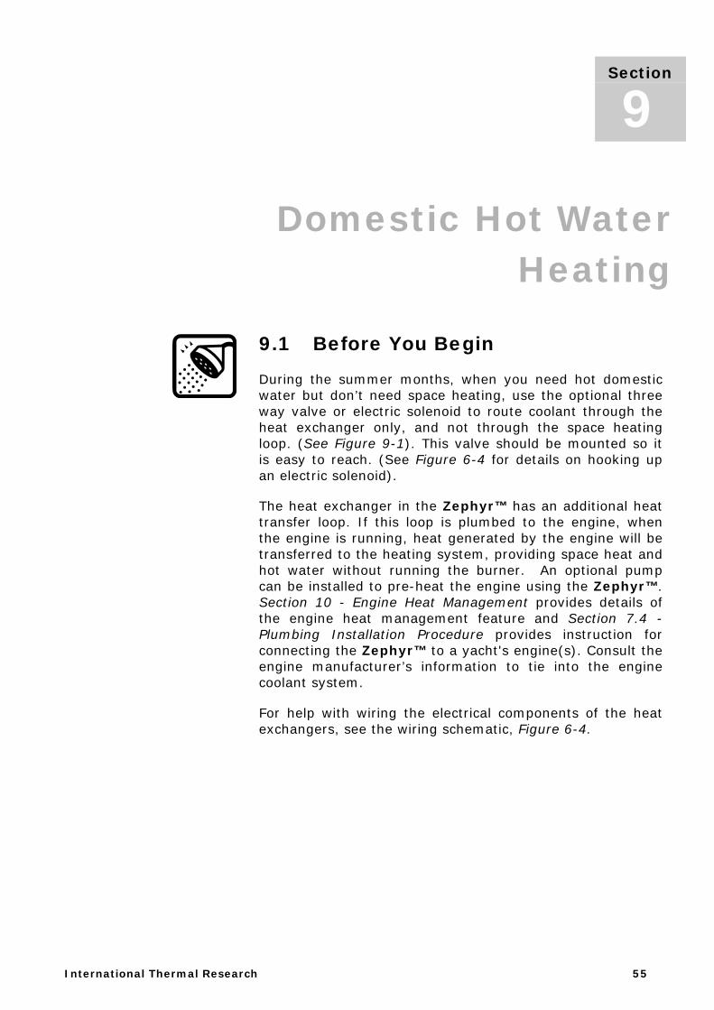
During the summer months, when you need hot domestic water but don’t need space heating, use the optional three way valve or electric solenoid to route coolant through the heat exchanger only, and not through the space heating loop. (See Figure 9-1). This valve should be mounted so it is easy to reach. (See Figure 6-4 for details on hooking up an electric solenoid).
The heat exchanger in the Zephyr™ has an additional heat transfer loop. If this loop is plumbed to the engine, when the engine is running, heat generated by the engine will be transferred to the heating system, providing space heat and hot water without running the burner. An optional pump can be installed to pre-heat the engine using the Zephyr™. Section 10 - Engine Heat Management provides details of the engine heat management feature and Section 7.4 - Plumbing Installation Procedure provides instruction for connecting the Zephyr™ to a yacht's engine(s). Consult the engine manufacturer’s information to tie into the engine coolant system.
For help with wiring the electrical components of the heat exchangers, see the wiring schematic, Figure 6-4.
Section
9
Section 10, Engine Heat Management
56 Installation Manual for Hurricane® Zephyr™ HW Heating System
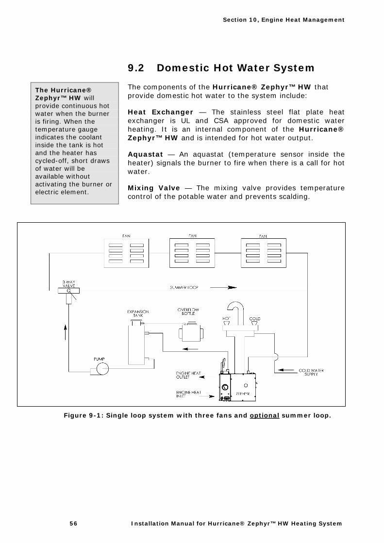
9.2 Domestic Hot Water System
The components of the Hurricane® Zephyr™ HW that provide domestic hot water to the system include:
Heat Exchanger — The stainless steel flat plate heat exchanger is UL and CSA approved for domestic water heating. It is an internal component of the Hurricane® Zephyr™ HW and is intended for hot water output.
Aquastat — An aquastat (temperature sensor inside the heater) signals the burner to fire when there is a call for hot water.
Mixing Valve — The mixing valve provides temperature control of the potable water and prevents scalding.
Figure 9-1: Single loop system with three fans and optional summer loop.
The Hurricane® Zephyr™ HW will provide continuous hot water when the burner is firing. When the temperature gauge indicates the coolant inside the tank is hot and the heater has cycled-off, short draws of water will be available without activating the burner or electric element.

International Thermal Research 57
Engine Heat Management 10.1 Engine Waste Heat Function
Besides providing space and domestic water heating, your Hurricane® Zephyr™ HW heater can be used to preheat a yacht's engine and to recycle waste heat produced by the engine.
A liquid cooled engine produces a large amount of waste heat while running. The Hurricane® Zephyr™ HW can use this heat to heat the yacht and provide domestic hot water if a thermostat or the domestic water aquastat is calling for heat. The Zephyr's heat exchanger will also preheat an engine by transferring heat to it from the Hurricane® Zephyr™ HW heater. An optional, manually switched pre-heat pump must be installed to enable this feature.
NOTE: The engine heat function can be used with the service switch ON or OFF.
Where there is a chance of contaminating domestic water when using a hydronic heating system, use a non-toxic, propylene-glycol based antifreeze with inhibitors generally recognized as safe (GRAS) by the FDA. Do not use automotive, ethylene glycol, or any undiluted or petroleum based antifreeze, as these are toxic.
Do not connect your engine cooling system directly to the heating system. Before connecting anything to your engine, consult your engine owner’s manual for any restrictions on plumbing into the engine cooling system.
Section
10
CAUTION
CAUTION
Section 10, Engine Heat Management
58 Installation Manual for Hurricane® Zephyr™ HW Heating System
10.2 Waste Heat Function
Installation Procedure
10.3 Engine Pre-Heat Function
As an option, the Hurricane® Zephyr™ HW can also be used to pre-heat a yacht's engine(s) before starting. The Hurricane® Zephyr™ HW has two plumbing connections on the back panel that connect to the engine coolant system. Pre-heating the engine makes it easier to start in cold temperatures.
The optional engine pre-heat function requires a manual switch mounted inside the yacht's interior (not supplied) which activates a separate pump (not included) to circulate engine coolant. In order for the Hurricane® Zephyr™ HW to provide heat to a cold engine, the burner and/or the electric heating element must be on, and a thermostat must be turned up to initiate a call for heat. If using the electric heating element, the yacht must be connected to a source of power (120/240VAC). See Section 6.4 - Wiring the Electric System, 120/240 VAC Options and Installation Procedure for using the electric heating element.
1 To make use of engine heat without running the burner, turn OFF the heater control switch located on the remote indicator panel. This will stop the burner from operating, but all other heater functions will operate normally. (Note: the burner switch can remain on while heating the system with heat from the boat's engine. The burner may fire initially if the system is cold, but will shut-off once the cycle temperature is reached and remain off as long as the engine is providing heat to the system). Start the engine.
2 When the engine temperature aquastat, located on the heat-exchanger, warms to its pre-set temperature, it will switch on the circulating pump of the heating system and distribute heat, assuming any thermostats or domestic water aquastat are calling for heat.
3 The circulating pump will continue to operate until the engine aquastat has cooled down, or until all thermostats or domestic water aquastats are satisfied.
Section 10, Engine Heat Management
International Thermal Research 59
10.4 Engine Pre-heat Installation Procedure
1 Mount a manual switch in an appropriate place in the interior, usually near the dashboard.
2 Wire the manual switch to the installed engine pre-heat water pump. Connect it to the main feed on the control board that connects to the boat’s power source beside the battery connection. (See Figure 6-4) The switch circuit should include a 5 amp fuse on the power side.
3 Connect the ground-wire of the engine pre-heat pump to boat battery's negative terminal.
4 To test the engine pre-heat function: if the Zephyr™ is not on and at operating temperature, turn ON the burner and/or electric heating element and turn up a thermostat to initiate a call for heat. The Hurricane® Zephyr™ will start distributing heat to the engine. Start the engine. The engine temperature gauge should indicate that the engine is warm.
5 Note that the burner outputs 33,000 BTUs, while the electric heating element outputs 5,100 BTUs. It will take much longer to pre-heat the engine with the electric heating element only.
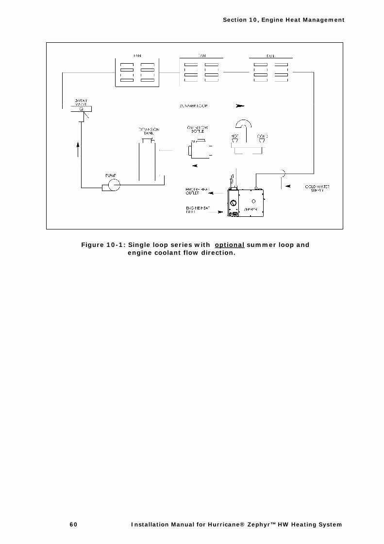
Section 10, Engine Heat Management
60 Installation Manual for Hurricane® Zephyr™ HW Heating System
Figure 10-1: Single loop series with optional summer loop and engine coolant flow direction.
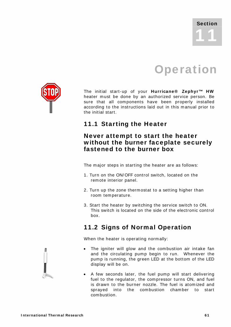
International Thermal Research 61
Section 10, Operation The initial start-up of your Hurricane® Zephyr™ HW heater must be done by an authorized service person. Be sure that all components have been properly installed according to the instructions laid out in this manual prior to the initial start.
11.1 Starting the Heater
Never attempt to start the heater without the burner faceplate securely fastened to the burner box
The major steps in starting the heater are as follows:
1. Turn on the ON/OFF control switch, located on the remote interior panel.
2. Turn up the zone thermostat to a setting higher than room temperature.
3. Start the heater by switching the service switch to ON. This switch is located on the side of the electronic control box.
11.2 Signs of Normal Operation
When the heater is operating normally:
• The igniter will glow and the combustion air intake fan and the circulating pump begin to run. Whenever the pump is running, the green LED at the bottom of the LED display will be on.
• A few seconds later, the fuel pump will start delivering fuel to the regulator, the compressor turns ON, and fuel is drawn to the burner nozzle. The fuel is atomized and sprayed into the combustion chamber to start combustion.
Section
11
Section 11, Operation
62 Installation Manual for Hurricane® Zephyr™ HW Heating System
• After the ignition period (about 10 seconds), the igniter shuts OFF, and the burner continues to operate. The heater will operate until all the zone thermostats are satisfied, or until the heater reaches its normal water operating temperature of approximately 180°F, as shown on the front of the Zephyr. Once the normal operating temperature is reached, the burner itself will cycle off and the combustion fan will operate for an additional two minutes to purge the burner.
• If a zone thermostat or domestic water heater aquastat is not satisfied, the circulating pump will continue to operate. If a thermostat cannot be satisfied by the residual heat in the system and the water temperature drops, the burner will restart and cycle until all thermostats are satisfied. Once all thermostats are satisfied, the heater will purge for 2 minutes, and the circulating pump will stop. Alternatively, the circulating pump and cabin fans can run using the A1 terminal on the control board (see Figure 6-4). An aquastat temperature sensor, wired to the A1 terminal on the control board, will control the engine heat function. The circulating pump will run once the engine heat is available (A1 connected to boat's battery's negative terminal) and any thermostat or domestic water aquastat is calling for heat. Note: The engine heat function can be used with the service switch ON or OFF. After the heater has been running for a little while, the water outlet of the heater case should become warm. If the water hose leaving the outlet of the heater does not warm up immediately after the circulating pump comes on, water is not circulating properly and air may be in the system. Turn the heater OFF and check water circulation.
11.3 Main Control Board Operation
Once the heater is operating normally, you must check the operating safety functions of the main board. To make sure the safety functions work properly, squeeze off the flow of air from the compressor. This can be done with your fingers, or by using a pair of smooth faced pliers. The hose may need to be pinched for several seconds before the heater stops. Pinching off the hose will shut off the flame. If you continue to block the air inlet, the heater will try to restart two more times. If it is unable to restart after two attempts, the heater will shut down, stopping the compressor and fuel pump. The control board will display a code '7.' Release the air hose, reset the control board, and
Section 11, Operation
International Thermal Research 63
the heater will continue with normal operation. This test assures the control board is functioning correctly.
11.4 Stopping the Heater for Seasonal Purposes
NEVER shut off the power to the Heater using the circuit breaker or a master switch, or disconnect the battery while the heater is running. Doing so will cause serious damage to the Heater, which will not be covered under warranty.
To turn the heater OFF, turn OFF the control switch, located on the remote interior panel, and turn OFF the service switch on the main control board box. The room thermostat or the remote interior panel switch can be switched ON or OFF at any time, without harming the heater. The heater will automatically run through the purge cycle, which takes about two minutes.
11.5 Using the Electric Heating Element
The electric heating element can be activated using the separate installed switch. If the switch has an indicator light, this light will come on. The electric heating element is operated independently of the control board. Sensors on the heater are monitoring tank temperature and controlling activation of the heating element. When the tank reaches a certain temperature, the heating element will automatically shut off. The heating element draws 12.5 Amps from the 120 VAC (6.25 Amps from the 240 VAC) circuit.
11.6 Stopping the Heater for Maintenance
To shut down the heater totally, for maintenance purposes make sure to follow the steps below in the order listed:
1. Turn OFF the service switch on the electronic control box.
2. Wait until the heater has completed the purge cycle and turned itself OFF.
3. Disconnect the power supply.
NOTICE
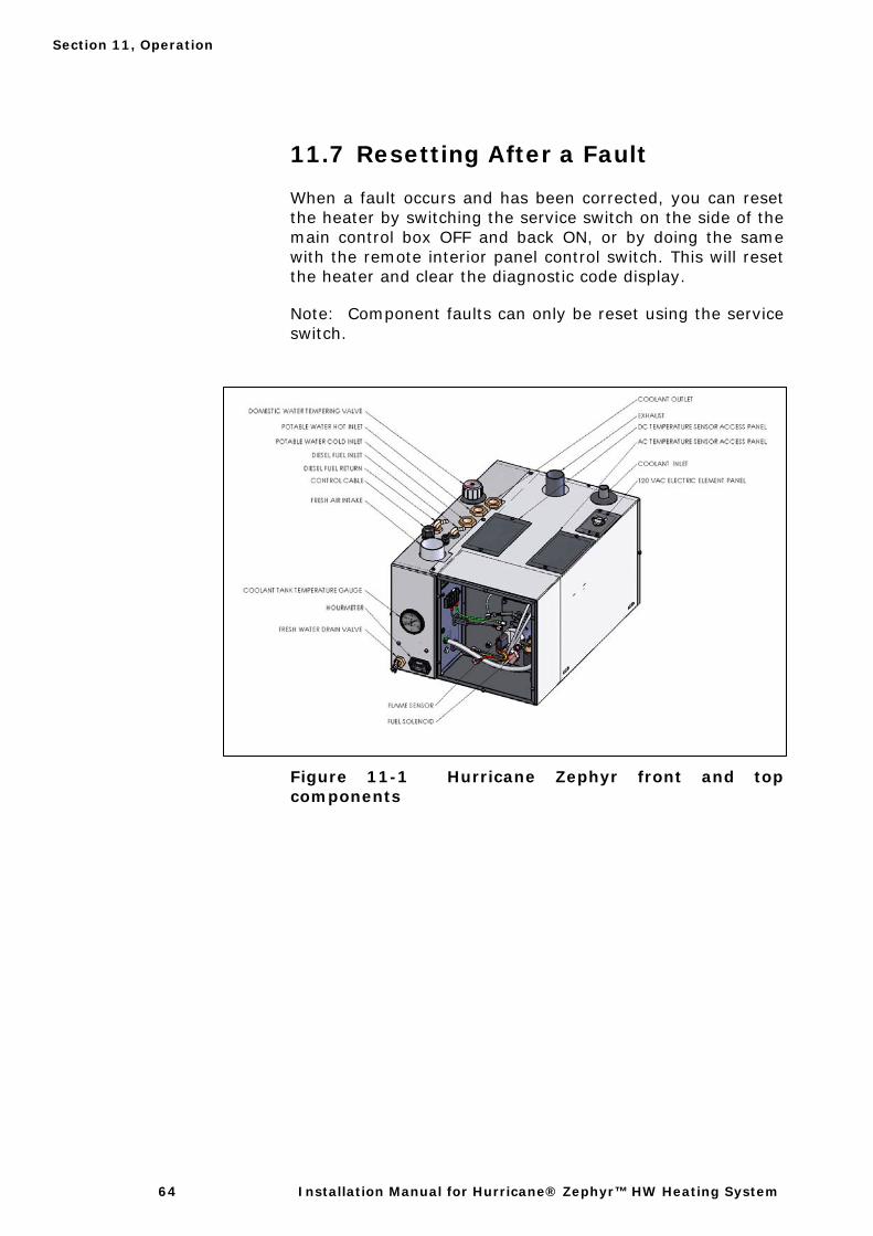
Section 11, Operation
64 Installation Manual for Hurricane® Zephyr™ HW Heating System
11.7 Resetting After a Fault
When a fault occurs and has been corrected, you can reset the heater by switching the service switch on the side of the main control box OFF and back ON, or by doing the same with the remote interior panel control switch. This will reset the heater and clear the diagnostic code display.
Note: Component faults can only be reset using the service switch.
Figure 11-1 Hurricane Zephyr front and top components
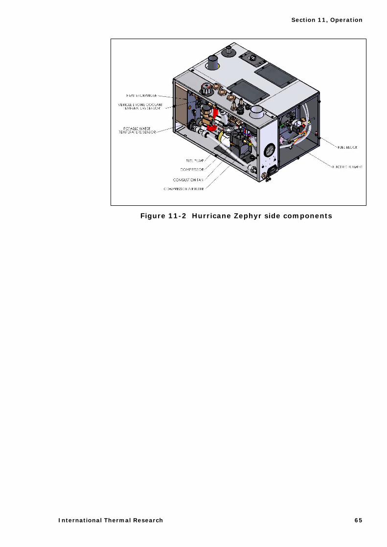
Section 11, Operation
International Thermal Research 65
Figure 11-2 Hurricane Zephyr side components

Section 11, Operation
66 Installation Manual for Hurricane® Zephyr™ HW Heating System
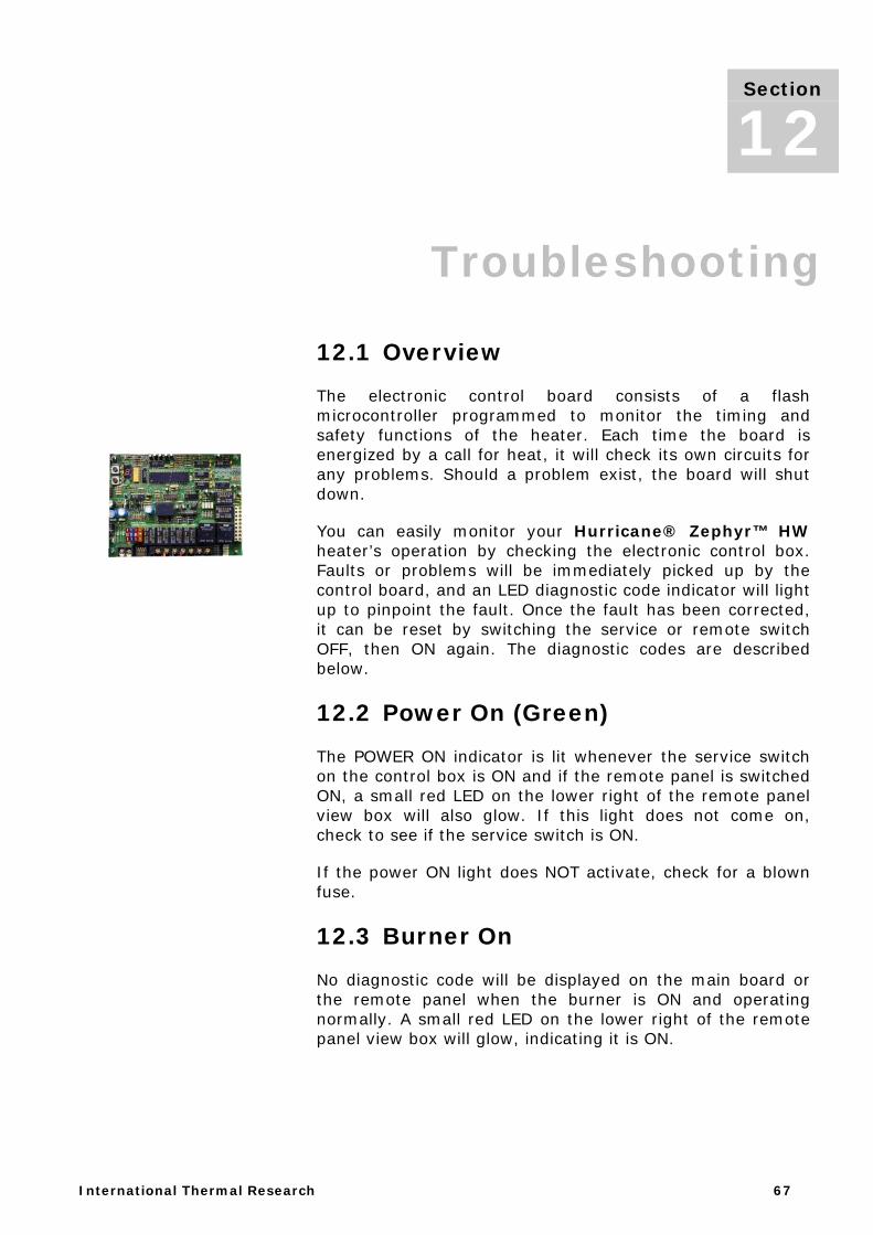
International Thermal Research 67
Section 11, Troubleshooting
12.1 Overview
The electronic control board consists of a flash microcontroller programmed to monitor the timing and safety functions of the heater. Each time the board is energized by a call for heat, it will check its own circuits for any problems. Should a problem exist, the board will shut down.
You can easily monitor your Hurricane® Zephyr™ HW heater’s operation by checking the electronic control box. Faults or problems will be immediately picked up by the control board, and an LED diagnostic code indicator will light up to pinpoint the fault. Once the fault has been corrected, it can be reset by switching the service or remote switch OFF, then ON again. The diagnostic codes are described below.
12.2 Power On (Green)
The POWER ON indicator is lit whenever the service switch on the control box is ON and if the remote panel is switched ON, a small red LED on the lower right of the remote panel view box will also glow. If this light does not come on, check to see if the service switch is ON.
If the power ON light does NOT activate, check for a blown fuse.
12.3 Burner On
No diagnostic code will be displayed on the main board or the remote panel when the burner is ON and operating normally. A small red LED on the lower right of the remote panel view box will glow, indicating it is ON.
Section
12
Section 12, Troubleshooting
68 Installation Manual for Hurricane® Zephyr™ HW Heating System
12.4 V - Service Switch Off
• The service switch is switched OFF.
• The burner will shut down if it has been running.
• The diagnostic code, V will be displayed.
• The control board will purge the system with the combustion fan and circulating pump for two minutes. At the end of the purge period, the system will power down and will go into a low power consumption mode (10mA max.). There will not be any display or LEDs lit.
12.5 9 - Remote Switch Off
The remote panel is switched OFF.
• The burner will shut down.
• The diagnostic 9 code will be displayed.
• The control board will purge the system with the combustion fan and circulating pump for two minutes.
If the remote switch is put in the ON position, the control board will resume operation and a small red LED will glow near the lower right hand corner of the remote panel view box. If there is no diagnostic code displayed or small LED glowing:
Make sure the service switch is ON.
Make sure the remote switch cable is plugged into the control box and remote switch.
Make sure the remote rocker switch is working.
Check the cable continuity.
12.6 < - Heater Cycling (Normal Operation)
The operating (cycling) aquastat installed on the coolant tank of the heater has been satisfied.
Section 12, Troubleshooting
International Thermal Research 69
• The burner will shut down.
• The diagnostic code, < will be displayed.
• The control board will purge the burner with the combustion fan for two minutes and then stop. The circulating pump will run until the last thermostat is satisfied, then purge for two minutes and stop.
• To maintain the system temperature the operating aquastat will cycle the burner off at 170° F (77°C) and on again at 140°F (60°C).
• If the heater cools and fails to resume operations and the diagnostic code < continues to be displayed, the aquastat is faulty or has an open connection.
12.7 T - Thermostats Off (Normal Operation)
All thermostats and aquastats are satisfied.
• The burner will shut down.
• The diagnostic code, T will be displayed.
• The control board will purge the system with the combustion fan and circulating pump for two minutes. When any thermostat or aquastat calls for heat, the heater will resume normal operation.
• If the heater fails to resume operations, check the thermostat and their connections.
12.8 0 - Voltage Low or High
The battery or power supply voltage is below 11Vdc or above 15Vdc
• The burner will shut down.
• The diagnostic code, 0 will be displayed.
• The buzzer will sound for 10 seconds.
Section 12, Troubleshooting
70 Installation Manual for Hurricane® Zephyr™ HW Heating System
• The control board will purge the system with the combustion fan and circulating pump for two minutes while it is checking if the voltage fault is still present.
• If the voltage fault has cleared, the control board will reset the alarm and restart the burner. If the condition has not cleared by the end of the purge period, the diagnostic code 0 will remain displayed. The control board will continue to check the voltage every half hour until the voltage fault has cleared and then restart the burner. To manually reset the fault, switch the service switch or the remote panel switch OFF then ON again.
12.9 1 - Overheat
The high temperature limit has been reached.
• The burner will shut down.
• The diagnostic code, 1 will be displayed.
• The buzzer will sound for 10 seconds.
• The control board will purge the system with the combustion fan and circulating pump for two minutes while it is checking if the overheat condition exists. If the condition exists, the diagnostic code 1 will continue to be displayed.
• In order to restart the burner, first check the circulating pump, the level of the coolant, and the movement of the coolant while the circulating pump is running. Reset the high limit aquastat (inside heater) and the fault (switch service or remote switch OFF then ON again). If the fault does not reset, check for a faulty aquastat and proper grounding.
If a diagnostic code I lights up and the heater is not in an overheat condition, check the ground from the heater ground wire to the battery. The ground wire should be a minimum 10 gauge and connected directly to the battery.
12.10 2 - Fuse Blown
One of the fuses on the control board has blown.
• The burner will shut down.
Section 12, Troubleshooting
International Thermal Research 71
• The diagnostic code, 2 will be displayed.
• The buzzer will sound for 10 seconds.
• The control board will purge the system with the combustion fan and circulating pump for two minutes while it is checking for a blown fuse.
• If a blown fuse exists, the diagnostic code 2 will continue to be displayed.
• In order to restart the burner, replace any blown fuses. Then reset the fault by switching the service switch or the remote panel switch OFF then ON again.
12.11 3 - Fuel Pump/Solenoid
The fuel pump or fuel solenoid has shorted.
• The burner will shut down.
• The diagnostic code, 3 will be displayed.
• The buzzer will sound for 10 seconds.
• The control board will purge the system with the combustion fan and circulating pump for two minutes.
• In order to restart the burner, check the fuel pump and solenoid for a short circuit. Then reset the fault by switching the service switch OFF then ON again.
• The remote panel switch does not reset short circuit faults.
12.12 4 - Igniter
The igniter is open or shorted
• The burner will shut down.
• The diagnostic code, 4 will be displayed.
• The buzzer will sound for 10 seconds.
• The control board will purge the system with the combustion fan and circulating pump for two minutes.
Section 12, Troubleshooting
72 Installation Manual for Hurricane® Zephyr™ HW Heating System
• In order to restart the burner, check the igniter and its connections. Then reset the fault by switching the service switch or the remote panel switch OFF then ON again if the igniter is open or by the service switch only if the igniter is shorted.
• The remote panel switch does not reset a short circuit fault.
12.13 5 - Combustion Fan
• The combustion fan is open circuit or shorted.
• The burner will shut down.
• The diagnostic code, 5 will be displayed.
• The buzzer will sound for 10 seconds.
• The control board will purge with the circulating pump for two minutes.
• In order to restart the burner, check the combustion fan. Then reset the fault by switching the service switch or the remote panel switch OFF then ON again if the combustion fan is open or by the service switch only if the combustion fan has shorted.
• The remote panel switch does not reset a short circuit fault.
12.14 6 - Water Pump
The water pump is shorted.
• The burner will shut down.
• The diagnostic code, 6 will be displayed.
• The buzzer will sound for 10 seconds.
• The control board will purge with the combustion fan for two minutes.
• In order to restart the burner, check the water pump. Then reset the fault by switching the service switch OFF then ON again.
Section 12, Troubleshooting
International Thermal Research 73
• The remote panel switch does not reset a short circuit fault.
12.15 7 - Flame Out
The flame went out or did not ignite.
• The burner will shut down.
• The diagnostic code, 7 will be displayed.
• The control board will try to restart the burner two more times. After two unsuccessful restart attempts, the buzzer will sound for 10 seconds.
• The control board will purge with the combustion fan and circulating pump for two minutes. The diagnostic code 7 will continue to be displayed.
• The single most common cause of flame faults is air entering the fuel system. This is normally caused by low fuel levels or loose fittings. As air accumulates and passes through the nozzle, it interrupts the fuel supply and shuts down the burner. When this happens, it may be necessary to reset the heater a few times to ensure all air has passed through the system. The Zephyr™ is equipped with a fuel manifold that helps to eliminate air in the supply line by allowing air to pass into the return line. Air may still, however, enter the nozzle and interrupt the fuel supply to the burner. If air continues to disrupt the flow of fuel into the nozzle, it is likely there is a leak somewhere in the fuel system.
• A flame-out may also be caused by a dirty nozzle or a dirty filter. When diagnosing a flame-out, check the condition of the nozzle and clean it or replace it if necessary. Also check the condition of the nozzle o-ring and nozzle filter. (See Section 13.3 - Nozzle)
• If the external fuel filter is dirty, it could create restriction in the fuel line and cause flame faults. Inspect and replace as necessary.
• A flame fault can also be caused by starvation of fuel if the heater’s fuel supply is shared with other equipment.
• Check connections on the fuel tank, fuel pump, and regulator. Check fuel lines for holes or cracks. Make sure
Section 12, Troubleshooting
74 Installation Manual for Hurricane® Zephyr™ HW Heating System
the nozzle or fuel filters are not clogged or excessively dirty.
• Check the airline hoses for any restriction of airflow through the compressor. Restrictions may be caused by a crimped hose, clogged air filter, or a loose or leaking air hose connecting the compressor outlet to the nozzle. Check the air filter inlet for any obstructions.
• Check for negative pressure in the area around the heater. When the engine is running, it can draw air back through the heater’s exhaust pipe. All intake air and exhaust connections must be tight.
• Check for restrictions or leaks in the combustion air in-take hose or exhaust pipe.
• Check for open circuit on fuel pump/solenoid and compressor.
• To restart the burner, check the fuel supply and clean the nozzle. Then reset the fault indicator by switching the service switch or the remote switch OFF then ON again.
• If the conditions that caused the flame fault have been addressed and the heater continues to not ignite, the thermal cutoff may have been activated by an overheat condition within the burner box. Using a multimeter, check for continuity across the leads of the thermal cutoff. The thermal cutoff is located inside the burner box, and is mounted at the top middle of the box. If there is no continuity, the heater MUST be inspected and the reason for the overheat condition determined and corrected before further use. A replacement thermal cutoff must be obtained from your dealer.
12.16 8 - Compressor
The air compressor has shorted.
• The burner will shut down.
• The diagnostic code, 8 will be displayed.
• The buzzer will sound for 10 seconds.
• The control board will purge the system with the combustion fan and circulating pump for two minutes.
Section 12, Troubleshooting
International Thermal Research 75
• In order to restart the burner, check the air compressor. Then reset the fault by switching the service switch OFF then ON again.
• The remote panel switch does not reset a short circuit fault.
12.17 ) - Bypass Mode
The bypass mode is a service feature to be used by authorized service personnel only. The bypass mode overrides the operating aquastat, remote switch, voltage fault, fuse blown fault, flame out fault, open igniter fault, open fan fault, and thermostats. All these safety devices will be bypassed for five minutes.
• While in the bypass mode, the diagnostic code, ) will be displayed and the Power ON LED will flash rapidly.
• If the heater cycling aquastat is satisfied or the overheat limit is reached, the burner will stop and purge for two minutes while displaying the diagnostic codes, heater cycling, < or I, for overheat. The Power ON LED will flash slowly. The heater must then cool down before continuing in bypass mode. The bypass mode will timeout in five minutes. After the first three minutes running in bypass mode, the heater will automatically purge for the last two minutes.
12.18 Water Pump On (Green)
The green light located directly under the LED digit on the main board will come on whenever the circulating water pump is energized.
12.19 LCD Readout Remote Panel (optional)
This panel will display the diagnostic explanation, which will match up to the diagnostic code on the main board. A small buzzer will sound for 10 seconds to alert you of a fault.
12.20 Flame Sensor Module
The Flame Sensor consists of: a sealed module with a photodiode aimed at the flame; a red LED indicator light
Section 12, Troubleshooting
76 Installation Manual for Hurricane® Zephyr™ HW Heating System
and 3 wires (red (+), black (-), and yellow (signal). All are connected to the main board). Under normal operating conditions, whenever the burner ignition begins, the red LED will flash once, indicating the red and black wires are connected and the module is receiving power and working properly. Once the burner is ignited, the LED will begin to flicker like the flame. If, for any reason, the flame is extinguished, the flickering will stop and the control board will shut down the heater.
If the yellow (signal) wire is disconnected, the board will shut down. If all wires are properly connected with module flashing and the board still shuts down, and diagnostic code 7 (Flame Out) appears, the board may be defective.
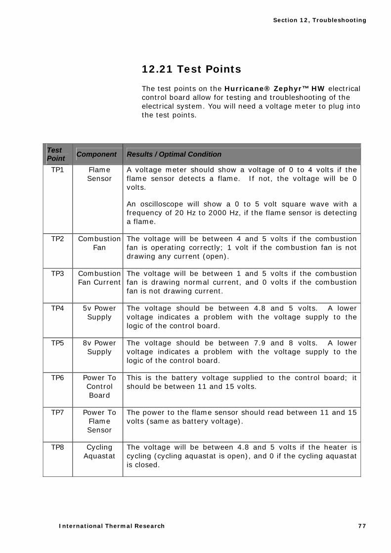
Section 12, Troubleshooting
International Thermal Research 77
12.21 Test Points
The test points on the Hurricane® Zephyr™ HW electrical control board allow for testing and troubleshooting of the electrical system. You will need a voltage meter to plug into the test points.
Test Point Component Results / Optimal Condition
TP1 Flame Sensor
A voltage meter should show a voltage of 0 to 4 volts if the flame sensor detects a flame. If not, the voltage will be 0 volts.
An oscilloscope will show a 0 to 5 volt square wave with a frequency of 20 Hz to 2000 Hz, if the flame sensor is detecting a flame.
TP2 Combustion Fan
The voltage will be between 4 and 5 volts if the combustion fan is operating correctly; 1 volt if the combustion fan is not drawing any current (open).
TP3 Combustion Fan Current
The voltage will be between 1 and 5 volts if the combustion fan is drawing normal current, and 0 volts if the combustion fan is not drawing current.
TP4 5v Power Supply
The voltage should be between 4.8 and 5 volts. A lower voltage indicates a problem with the voltage supply to the logic of the control board.
TP5 8v Power Supply
The voltage should be between 7.9 and 8 volts. A lower voltage indicates a problem with the voltage supply to the logic of the control board.
TP6 Power To Control Board
This is the battery voltage supplied to the control board; it should be between 11 and 15 volts.
TP7 Power To Flame Sensor
The power to the flame sensor should read between 11 and 15 volts (same as battery voltage).
TP8 Cycling Aquastat
The voltage will be between 4.8 and 5 volts if the heater is cycling (cycling aquastat is open), and 0 if the cycling aquastat is closed.
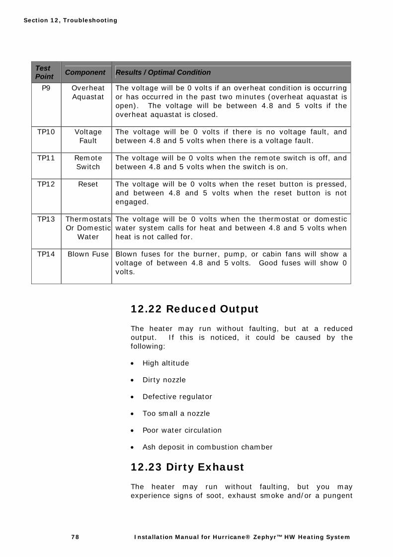
Section 12, Troubleshooting
78 Installation Manual for Hurricane® Zephyr™ HW Heating System
Test Point Component Results / Optimal Condition
P9 Overheat Aquastat
The voltage will be 0 volts if an overheat condition is occurring or has occurred in the past two minutes (overheat aquastat is open). The voltage will be between 4.8 and 5 volts if the overheat aquastat is closed.
TP10 Voltage Fault
The voltage will be 0 volts if there is no voltage fault, and between 4.8 and 5 volts when there is a voltage fault.
TP11 Remote Switch
The voltage will be 0 volts when the remote switch is off, and between 4.8 and 5 volts when the switch is on.
TP12 Reset The voltage will be 0 volts when the reset button is pressed, and between 4.8 and 5 volts when the reset button is not engaged.
TP13 Thermostats Or Domestic
Water
The voltage will be 0 volts when the thermostat or domestic water system calls for heat and between 4.8 and 5 volts when heat is not called for.
TP14 Blown Fuse Blown fuses for the burner, pump, or cabin fans will show a voltage of between 4.8 and 5 volts. Good fuses will show 0 volts.
12.22 Reduced Output
The heater may run without faulting, but at a reduced output. If this is noticed, it could be caused by the following:
• High altitude
• Dirty nozzle
• Defective regulator
• Too small a nozzle
• Poor water circulation
• Ash deposit in combustion chamber
12.23 Dirty Exhaust
The heater may run without faulting, but you may experience signs of soot, exhaust smoke and/or a pungent
Section 12, Troubleshooting
International Thermal Research 79
smell. This is usually caused by the wrong fuel to air ratio. Fuel to air ratio can be affected by the following:
• Low voltage
• High altitude
• Dirty compressor air filter
• Low compressor air output
• Restricted combustion air flow
• Low combustion fan output
• Partially clogged grooves in nozzle distributor
Section 12, Troubleshooting
80 Installation Manual for Hurricane® Zephyr™ HW Heating System
12.24 Carbon Monoxide Dangers
The American Boat and Yacht Council Inc. (ABYC) states:
Section 5.111: "Where heater is installed in an engine or bilge space, 100% fresh air shall be supplied for combustion."
Section 6.1: "Burners shall be of the mechanical draft type which employs a power driven fan, blower or other mechanism supplying air for combustion."
This means 100% fresh combustion air must be mechanically delivered through a sealed duct directly to the heater from outdoors. This is the recommended procedure no matter where the heater is installed. When combustion air is drawn from an unventilated heated space, the heater flame will become increasingly yellow as the oxygen in that space is consumed. An oxygen-starved flame produces excessive carbon monoxide (CO), some of which can easily escape the exhaust. Carbon monoxide is a colorless, odourless, tasteless gas produced any time you burn a carbon-based fuel such as gasoline, wood, charcoal, kerosene, propane, or diesel. It disperses freely in the air and can accumulate in enclosed spaces or air pockets. RV owners and boaters are especially vulnerable to the dangers of CO because these yachts have gas or diesel engines, as well as fuel-burning appliances, and their enclosed spaces can accumulate CO. CO is a cumulative poison; it can have fatal effects even at low concentrations. A normal exhaust system is under constant attack from salt corrosion, gases, vibration, and impacts. It is important to inspect your exhaust system on a regular basis. Start with a visual inspection for signs of damage, and check each joint for discoloration from exhaust gas leaks or other signs that may indicate a possible leak. Inspect the entire system for corrosion, and check that clamps are in good condition and are secure.
Also, ensure that all ventilation systems are in good working order and not blocked. A poorly maintained heating system can produce excessive CO, so it’s important to keep your Hurricane® Zephyr™ HW clean, maintained on a regular basis, and in proper running condition. Hurricane® hydronic heating systems should never produce smoke or a detectable odour. If this occurs, the heater requires service.
International Thermal Research 81
Section 12, Maintenance
13.1 The First Few Weeks
About two weeks after your Hurricane® Zephyr HW heater has been installed, you should conduct a general inspection of the entire system.
Check for any leaks in the exhaust system, fuel line system, coolant system and fresh water line system.
It is strongly recommended that the Hurricane® Zephyr™ HW heater be started and allowed to run through one complete heating cycle at least every 30 to 45 days to ensure its proper function and to verify the proper operation of all components.
13.2 Adding Coolant
PRECAUTION: Where there is a chance of contaminating your domestic water when using a heating system, always use a non-toxic Propylene-glycol based antifreeze with additives generally recognized as safe (GRAS) by the FDA.
Do not use automotive, ethylene glycol, or any undiluted or petroleum based antifreeze as they can cause severe personal injury.
IT IS VERY IMPORTANT THAT YOU NEVER USE WATER ONLY AS A HEAT TRANSFER FLUID.
We recommend you use a mixture of 50% distilled water and 50% antifreeze as a heat transfer fluid. Cold weather conditions may dictate that more than 50% antifreeze is required in the coolant mixture. If this is the case, note that
Section
13
NOTICE

Section 13, Maintenance
82 Installation Manual for Hurricane® Zephyr™ HW Heating System
the added viscosity of the antifreeze solution can cause circulation problems over time. Your antifreeze/water mixture should be changed every three years.
Antifreeze wears out and can become very acidic. USE DISTILLED WATER AS TOP-UP to replace system fluid lost to normal evaporation. Be cautious of the dilution levels of the antifreeze in the system and the possibility of freezing. Always winterize the freshwater system if left unheated in freezing temperatures.
A coolant conditioner can be added to keep the coolant alkaline. These inhibitors also prevent the coolant from forming calcium scales. If a conditioner is not installed in your system, check the pH level yearly. The components inside the heater should not normally require maintenance, except for periodic checks for obvious problems, such as leaks or overheating.
Note: Service kits are available from ITR/Calcutt Boats for 1, 3 and 5 year service intervals. These kits contain the parts normally replaced during the respective service/maintenance intervals.
13.3 Nozzle
Nozzle problems such as clogging will result in a poor, small blue flame. Once the nozzle is removed from the fuel block, it can be disassembled and cleaned as part of regular maintenance. To disassemble the nozzle, position it vertically. Hold the nozzle head with a 5/8” box-end wrench, and the stem with a crescent wrench. Be sure to keep the wrench square on the stem, and do not use a tool with sharp edges, as the soft brass can damage easily. Turn the stem clockwise to unscrew it from the nozzle head. Keeping the nozzle vertical, carefully remove the nozzle head from the stem. This will expose the fuel distributor that sits in the end of the stem. Remove the o-ring from the stem. Clean all of the parts with regular automotive brake cleaner or a suitable solvent, using a rag and cotton swab. Blow air through the orifice of the distributor, stem and nozzle head. Make sure all parts are free of debris. Do not poke anything through the holes of any of the nozzle parts. Clean these only with solvent and compressed air. Reassemble the nozzle carefully, making sure the fuel distributor is seated properly in the stem. Do not over- tighten the nozzle head and stem connection. Replace the O-ring. A damaged, leaking O-ring will cause poor burning
Section 13, Maintenance
International Thermal Research 83
performance and possible flame-outs. Always lubricate the O-ring with a small amount of diesel fuel or silicone grease prior to replacing the nozzle into the fuel block.
13.4 Fuel Lines and Filter
Regularly inspect fuel lines for cracks, abrasion, abnormal wear, possible future damage and loose fittings or clamps. Filters should be replaced every season, even if they appear to be clean. Use a 10 micron filter to filter your main fuel supply.
13.5 Combustion Chamber
Quality of fuels vary, and some fuels may leave ash deposits in the burn chamber. The burner and combustion tube must be removed and the combustion chamber must be vacuumed clean every 1000 hours. If this is neglected, the exhaust will be restricted and will cause the combustion chamber to burn out. The exhaust pipe should be checked and vacuumed as required.
13.6 Checking Hoses and Tubes
Every so often, check the coolant hoses and tubes for leaks or weak points and make sure all clamps are tight. Replace any sections of worn hose immediately. Also check for flow restrictions and ensure that any installed bend supports are in their proper position. Check for unsupported hose or tubing and check and eliminate the potential for future problems.
13.7 Electrical System
The electronic control panel should not normally require servicing, except for the following:
• Make sure that all connections are secure.
• Periodically, do a voltage test to ensure that you are getting 12 volts from the battery.
• Check for corrosion of wires.
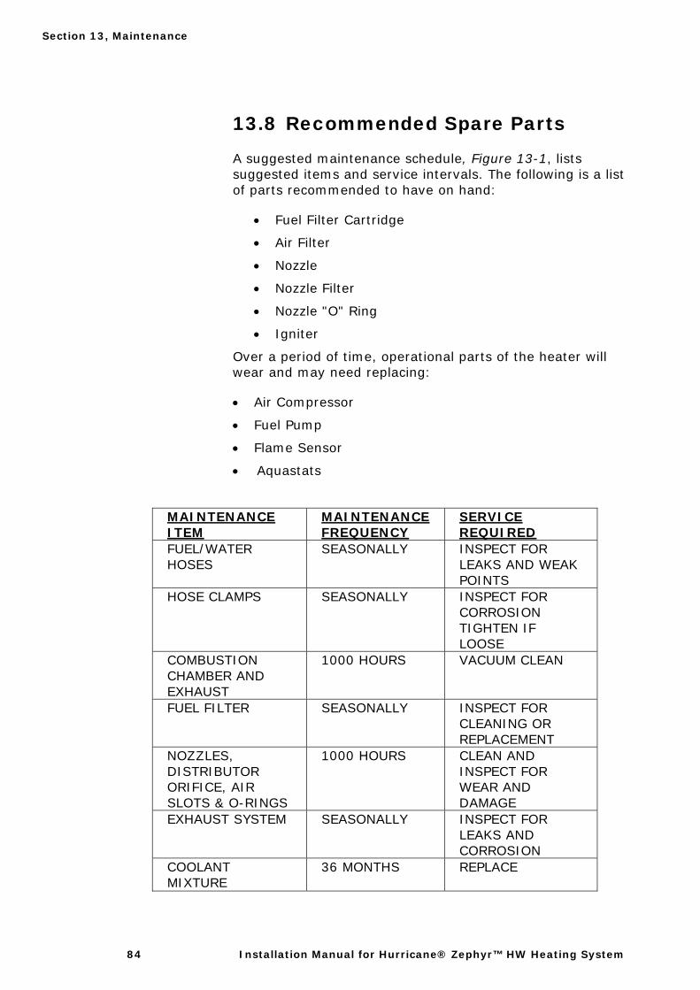
Section 13, Maintenance
84 Installation Manual for Hurricane® Zephyr™ HW Heating System
13.8 Recommended Spare Parts
A suggested maintenance schedule, Figure 13-1, lists suggested items and service intervals. The following is a list of parts recommended to have on hand:
• Fuel Filter Cartridge
• Air Filter
• Nozzle
• Nozzle Filter
• Nozzle "O" Ring
• Igniter
Over a period of time, operational parts of the heater will wear and may need replacing:
• Air Compressor
• Fuel Pump
• Flame Sensor
• Aquastats
MAINTENANCE ITEM
MAINTENANCE FREQUENCY
SERVICE REQUIRED
FUEL/WATER HOSES
SEASONALLY INSPECT FOR LEAKS AND WEAK POINTS
HOSE CLAMPS SEASONALLY INSPECT FOR CORROSION TIGHTEN IF LOOSE
COMBUSTION CHAMBER AND EXHAUST
1000 HOURS VACUUM CLEAN
FUEL FILTER SEASONALLY INSPECT FOR CLEANING OR REPLACEMENT
NOZZLES, DISTRIBUTOR ORIFICE, AIR SLOTS & O-RINGS
1000 HOURS CLEAN AND INSPECT FOR WEAR AND DAMAGE
EXHAUST SYSTEM SEASONALLY INSPECT FOR LEAKS AND CORROSION
COOLANT MIXTURE
36 MONTHS REPLACE
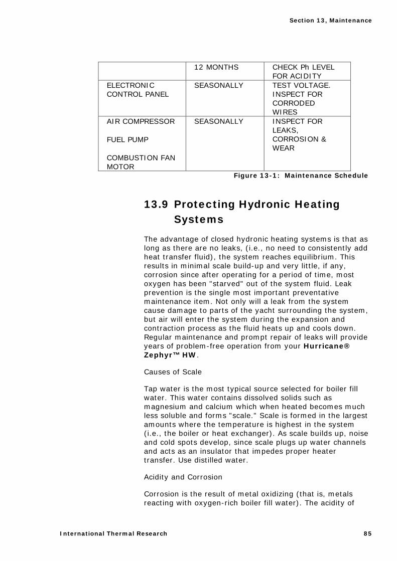
Section 13, Maintenance
International Thermal Research 85
12 MONTHS CHECK Ph LEVEL FOR ACIDITY
ELECTRONIC CONTROL PANEL
SEASONALLY TEST VOLTAGE. INSPECT FOR CORRODED WIRES
AIR COMPRESSOR
FUEL PUMP
COMBUSTION FAN MOTOR
SEASONALLY INSPECT FOR LEAKS, CORROSION & WEAR
Figure 13-1: Maintenance Schedule
13.9 Protecting Hydronic Heating Systems
The advantage of closed hydronic heating systems is that as long as there are no leaks, (i.e., no need to consistently add heat transfer fluid), the system reaches equilibrium. This results in minimal scale build-up and very little, if any, corrosion since after operating for a period of time, most oxygen has been "starved" out of the system fluid. Leak prevention is the single most important preventative maintenance item. Not only will a leak from the system cause damage to parts of the yacht surrounding the system, but air will enter the system during the expansion and contraction process as the fluid heats up and cools down. Regular maintenance and prompt repair of leaks will provide years of problem-free operation from your Hurricane® Zephyr™ HW.
Causes of Scale
Tap water is the most typical source selected for boiler fill water. This water contains dissolved solids such as magnesium and calcium which when heated becomes much less soluble and forms "scale." Scale is formed in the largest amounts where the temperature is highest in the system (i.e., the boiler or heat exchanger). As scale builds up, noise and cold spots develop, since scale plugs up water channels and acts as an insulator that impedes proper heater transfer. Use distilled water.
Acidity and Corrosion
Corrosion is the result of metal oxidizing (that is, metals reacting with oxygen-rich boiler fill water). The acidity of
Section 13, Maintenance
86 Installation Manual for Hurricane® Zephyr™ HW Heating System
any liquid (including water) is a good indicator of how much corrosion will actually take place. As a rule of thumb, boiler fill water should have a pH greater than 7 and less than 10.5. The key to preventing corrosion is to make sure that the heating system is free of leaks and there is no need to replace it with fresh, oxygen rich, boiler fill water. Corrosion inside a hydronic heating system stops quite quickly as the fill water stabilizes and becomes oxygen-starved. The pH should be measured at least annually.
Since most hydronic heating systems are comprised of different metals (e.g., iron, copper, etc.), and since boiler fill water is an electrolyte (that is, it will conduct electrical current), electro-chemical reactions ("galvanic" reactions) can take place. As the fill water stabilizes, however, it becomes a very weak electrolyte, so galvanic corrosion rarely becomes a problem - as long as the system remains leak-free.
Preventative Treatments
Corrosion and scale inhibitors are relatively inexpensive. Ideally, they should be applied only once, at the time of a new installation, or whenever a system has been completely drained. Boiler water treatment specialists agree that the prevention of leaks and the elimination of frequent boiler water top-up are high priorities in hydronic system maintenance.
International Thermal Research 87
Section 13, Warranty and Service
14.1 Attention Purchaser and Installer
General Warranty
• ITR warrants the Hurricane®II/IIL/Combi, Zephyr, SCH25, Water Heater by ITR, (referred to as “heater(s)”) and all other ITR supplied accessories and components with the original purchase to be free of defects in materials and workmanship under design usage and service conditions for two (2) years from the heater serial number label manufacturing date or installation date, or 2000 hours of operation, whichever is first. Warranty replacement parts are covered for the remainder of the heater’s warranty.
• You must install the Product in compliance with the specifications, standards, and instructions in the Installation Manual.
• If you need to depart from the manual, you must first consult and obtain the written approval of Calcutt Boats or ITR. Otherwise, your warranty may be voided or limited.
• Systems that are not installed to the published installation instructions (unless with prior written approval of Calcutt Boats or ITR) will be ineligible for warranty coverage.
Fill in the enclosed Warranty Card completely. It must be signed by the Owner and returned to Calcutt Boats within 30 days of the date of the original installation. The Owner cannot transfer this warranty. Before mailing, make photocopies of the completed Warranty Card for your
Section
14
Section 14, Warranty and Service
88 Installation Manual for Hurricane® Zephyr™ HW Heating System
records. It will be a valuable reference if you need warranty repairs in the future.
14.2 Limited Warranty
The following warranties are in lieu of all other warranties and conditions. ITR makes no other warranties, representations, or conditions, express or implied. Expressly excluded are all implied or statutory warranties or conditions of merchantability of fitness for a particular purpose, and those arising by statute or otherwise in law or from dealing or trade usage.
The stated express warranties are in lieu of all liabilities or obligations for damages arising out of or in connection with the delivery, use, performance, or licensing of the Product or in connection with any services performed. In no event whatsoever will Calcutt Boats or ITR be liable for indirect, consequential, exemplary, incidental, special, or similar damages, including but not limited to, lost profits, lost business revenue, failure to realize expected savings, other commercial or economic loss of any kind or any claim against ITR by any other party arising out of or in connection with the sale, delivery, use, performance, or repair of the Product, or in connection with any services performed, even if Calcutt Boats or ITR has been advised of the possibility of such damages, whether based upon warranty, contract, or negligence. Calcutt Boats or ITR’s maximum liability shall not in any case exceed the contract price for the Products claimed to be defective.
No one is authorized to increase, alter, or enlarge Calcutt Boats or ITR’s responsibilities or obligations under these warranties.
14.3 Owner’s Responsibilities
If any warrantable failures occur before the expiration of the warranty, the Owner must give notice of such failures to Calcutt Boats or ITR or to the authorized ITR dealer from which the Product was originally purchased, and obtain written approval for the warranty repair.
The Owner is responsible for the following costs in case of a warrantable failure:
• shipping and insurance costs to deliver the defective Product to the dealer or ITR (if necessary)
Section 14, Warranty and Service
International Thermal Research 89
• all repairs made to equipment ancillary to the Product, including the boat, engine, and other associated components of the boat in which the Product is installed
• lodging, meals, and other incidental expenses incurred by the Owner as a result of a warrantable failure
• “down time” expenses and all business costs and losses resulting from the warrantable failure
14.4 Not Covered Under Warranty
Warranty will be voided or not extended in the following circumstances:
• Owner fails to notify ITR or the authorized ITR dealer from which the Product was originally purchased about a warrantable failure and to obtain prior written approval for warranty repair.
• Original serial number on Product or electrical control board has been removed, altered, or is unreadable.
• Product has been modified or uses non-standard parts not approved by ITR.
• Product has been abused (such as by dropping it), damaged, vandalized, or has received improper maintenance.
• Product has been run dry or operated without appropriate antifreeze, causing damage to the heat exchanger, pump seals, etc.
• Product has been exposed to an environment detrimental to its effective operation, such as excessively wet, dirty, or hot areas.
Also not covered under warranty:
• Parts or Products no longer within the manufacturer’s warranty period.
• Parts or Products installed or used in a manner contrary to ITR’s printed instructions without Calcutt Boats or ITR’s prior written permission.
• Normal wear and tear of parts, including but not limited to, fuel filter, air filter, nozzles, fuses, igniter, electrical motors, fuel pumps, air compressors, and carbon brushes.
• Product malfunctions due to improper installation of parts or Products, including but not limited to
Section 14, Warranty and Service
90 Installation Manual for Hurricane® Zephyr™ HW Heating System
malfunctions causing inadequacies in air, fuel, or coolant flow; voltage problems due to improper wiring; and shock or vibration.
• Progressive damage to the engine or boat caused by failure of the Product or an improper installation.
• Diagnosis or repairs to fix problems not directly related to the Product or due to empty fuel tanks or poor fuel quality, fuel additives, acidic water, electrolysis, or any chemical reactions.
• Travel time and expenses by an ITR dealer.
• Removal and re-installation expenses for the ITR heater.
14.5 Customer Service Calls
ITR warrants the ITR heater and the Dealer warrants the installation.
If you have a service problem, first check the Troubleshooting section of the Owner’s Manual to determine if your problem is addressed. Also ensure you are familiar with the design and installation setup.
When calling ITR or the Dealer with a service problem, have the following information ready at hand:
• model number and serial number of the Product • a detailed description of the problem • your Installation Manual and Owner’s Manual
• Depending on your location, an authorized service person may be able to visit your boat or yacht to help troubleshoot problems and repair your Product. Such service calls are at the Owner’s expense. Regardless, you must obtain written approval from ITR or the Dealer for any warranty repair before it is undertaken. All repairs done under warranty are subject to the terms and conditions of the flat-rate manual.
14.6 Returns
If a service call by an authorized service person is not feasible, the Owner must do the following to obtain warranty service:
1. Immediately contact ITR (or your Dealer) and provide a full description of the problem.
Section 14, Warranty and Service
International Thermal Research 91
2. Obtain (in writing) a Return or Repair Material Authorization (RMA) number from ITR for any warranty, return, repair, or service. ITR will refuse any return package and will not authorize service or repairs without a RMA number. (For repairs by authorized Dealers, the dealer must obtain an authorized RMA number from ITR before warranty work commences.)
3. When shipping your Product, pack securely, show the RMA and serial number of the Product on the outside of the shipping container, and ship prepaid and insured.
4. Provide written details of the problems, date of installation, proof of purchase, and a return address.
After repair or replacement of the Products still under warranty, ITR will pay return shipping charges. All repairs done under warranty are subject to the terms and conditions of the flat-rate manual.
14.7 Telephone Service
Service information given over the telephone, by fax or by email is given only in good faith as an accommodation to the customer. Such information should not be relied upon without an independent verification of its applicability to the customer’s particular situation. For customer service or other information, contact:
Call the Dealer from whom you bought the heater, or:
OUTSIDE EUROPE: EUROPE:
International Thermal Research Calcutt Boats Ltd.
2431 Simpson Road, Tomlow Road, Stockton,
Richmond, BC, Canada, Southam, CV47 8HX,
V6X 2R2 United Kingdom
Tel: +1 604-278-1272 Tel: +44 1926 813757
Fax: +1 604-278-1274 Fax: +44 1926 814091
Email: [email protected] Email: [email protected]
Web: www.itrheat.com Web: www.dieselheating.com

International Thermal Research 92
OWNER NOTES
HURRICANE® Zephyr Serial No:
Installation Date:
Installed by: