Installation and Operating Manual - Swimming Pool … · Installation and Operating Data...
16
Installation and Operating Data Installation and Operating Manual H0570800C Jandy ® Valve Actuator Model JVA2444 FOR YOUR SAFETY - This product must be installed and serviced by authorized personnel, qualified in pool/spa installation. Improper installation and/or operation can create an unwanted electrical hazard which can cause serious injury, property damage, or death. Improper installation and/or operation will void the warranty. This manual contains important information about the installation, operation and safe use of this product. This information should be given to the owner/operator of this equipment. WARNING
Transcript of Installation and Operating Manual - Swimming Pool … · Installation and Operating Data...

Installation and Operating Data
Installation and Operating Manual
H05
7080
0C
Jandy® Valve ActuatorModel JVA2444
FOR YOUR SAFETY - This product must be installed and serviced by authorized personnel, qualified in pool/spa installation. Improper installation and/or operation can create an unwanted electrical hazard which can cause serious injury, property damage, or death. Improper installation and/or operation will void the warranty.
This manual contains important information about the installation, operation and safe use of this product. This information should be given to the owner/operator of this equipment.
WARNING

Page �
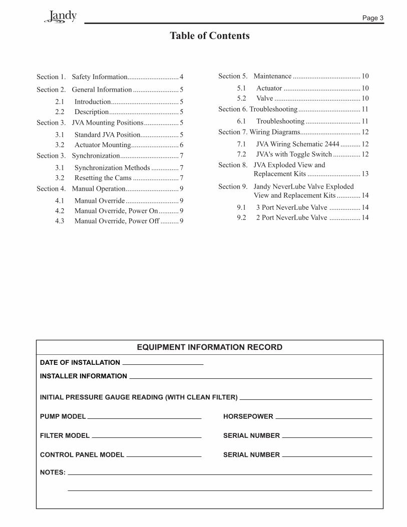
Table of Contents
Section 1. Safety Information ............................ 4
Section 2. General Information ......................... 5
2.1 Introduction ..................................... 52.2 Description ...................................... 5
Section 3. JVA Mounting Positions ................... 5
3.1 Standard JVA Position..................... 53.2 Actuator Mounting .......................... 6
Section 3. Synchronization ................................ 7
3.1 Synchronization Methods ............... 73.2 Resetting the Cams ......................... 7
Section 4. Manual Operation ............................. 9
4.1 Manual Override ............................. 94.2 Manual Override, Power On ........... 94.3 Manual Override, Power Off .......... 9
Section 5. Maintenance ..................................... 10
5.1 Actuator .......................................... 105.2 Valve ............................................... 10
Section 6. Troubleshooting .................................. 11
6.1 Troubleshooting .............................. 11Section 7. Wiring Diagrams................................. 12
7.1 JVA Wiring Schematic 2444 ........... 127.2 JVA's with Toggle Switch ............... 12
Section 8. JVA Exploded View and Replacement Kits ............................. 13
Section 9. Jandy NeverLube Valve Exploded View and Replacement Kits ............. 14
9.1 3 Port NeverLube Valve ................. 149.2 2 Port NeverLube Valve ................. 14
DATE OF INSTAllATION
INSTAllER INFORMATION
INITIAl PRESSURE GAUGE READING (WITh clEAN FIlTER)
PUMP MODEl hORSEPOWER
FIlTER MODEl SERIAl NUMbER
cONTROl PANEl MODEl SERIAl NUMbER
NOTES:
EqUIPMENT INFORMATION REcORD

Page �
Section 1. Safety Information
IMPORTANT SAFETY INSTRUcTIONS PERTAINING TO A RISK OF FIRE, ElEcTRIc ShOcK, OR INJURY TO PERSONS
READ AND FOllOW All INSTRUcTIONSWhen installing and using this electrical equipment, basic safety precautions should always be followed, including the following:
SAVE ThESE INSTRUcTIONS
This product must be installed and serviced by authorized personnel, qualified in pool/spa installation. Improper installation and/or operation can create an unwanted electrical hazard which can cause serious injury, property damage, or death. Improper installation and/or operation will void the warranty.
WARNING
WARNINGThis manual contains important information about the installation, operation and safe use of this product. This information should be given to the owner/operator of this equipment.

Page 5
Section 2. General Information
2.1 Introduction
This manual contains information for the proper installation and operation of Jandy® Valve Actuators (JVA). Procedures in this manual must be followed exactly. To obtain additional copies of this manual contact 707-776-8200, ext. 237. For address information see back cover.
2.2 Description
Jandy Valve Actuators are designed to meet the needs of today's more advanced, automatic pool equipment. These fully adjustable actuators offer versatile pool/spa automation with easy setups. All actuators work with the Jandy AquaLink® RS Control Systems and are available in 24 volt units.
JVA 2444 Specifications
Voltage 2� VAC
Amperage 0.75 AMPS
Cycles 60 Hz
WireBlackRedWhite
�-conductorCommonSwitch LegSwitch Leg
Figure 2. Standard JVA Mounting
A
b (common Port)
c
A
b (common Port)
c
Figure 1. Standard Plumbing
Water flow into or out of the valve
Remove these four (4) screws for Standard Position
Section 3. JVA Mounting Positions
3.1 Standard JVA Position
Standard Plumbing position is with the middle port (B) as the incoming or common port to the valve (see Figure 1).
Standard Mounting position is with the main body of the actuator over port B (see Figure 2).
NOTE If the valve(s) are plumbed with port B as the common port (Standard Plumbing) and the main body of the actuator(s) are mounted over port B (Standard Mounting), there is no need to adjust the actuator cams.
Page 6
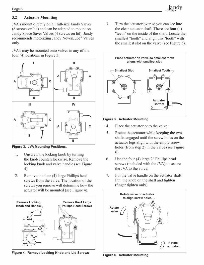
3. Turn the actuator over so you can see into the clear actuator shaft. There are four (4) "teeth" on the inside of the shaft. Locate the smallest "tooth" and align this "tooth" with the smallest slot on the valve (see Figure 5).
Figure 4. Remove Locking Knob and Lid Screws Figure 6. Actuator Mounting
Rotate valve or actuator to align screw holes
Rotate valve
Rotate actuator
Figure 5. Actuator Mounting
Place actuator on valve so smallest tooth aligns with smallest slot.
Smallest Slot
Actuator bottom
Smallest Tooth
1. Unscrew the locking knob by turning the knob counterclockwise. Remove the locking knob and valve handle (see Figure 4).
2. Remove the four (4) large Phillips head screws from the valve. The location of the screws you remove will determine how the actuator will be mounted (see Figure 4).
3.2 Actuator Mounting
JVA’s mount directly on all full-size Jandy Valves (8 screws on lid) and can be adapted to mount on Jandy Space Saver Valves (4 screws on lid). Jandy recommends motorizing Jandy NeverLube® Valves only.
JVA’s may be mounted onto valves in any of the four (4) positions in Figure 3.
A
Figure 3. JVA Mounting Positions.
b
c
A
b
c
III
III
IV
A
A
bb
c
c
4. Place the actuator onto the valve.
5. Rotate the actuator while keeping the two shafts engaged until the screw holes on the actuator legs align with the empty screw holes (from step 2) in the valve (see Figure 6).
6. Use the four (4) large 2" Phillips head screws (included with the JVA) to secure the JVA to the valve.
7. Put the valve handle on the actuator shaft. Put the knob on the shaft and tighten (finger tighten only).
Remove Locking Knob and handle
Remove the 4 large Phillips Head Screws

Page 7
Section 3. Synchronization
Figure 8. JVA Synchronization, Toggle
ON 1
OFF
ON 2
On/Off Switch is located on the
bottom of the JVA
Figure 7. JVA Synchronization, Example
Suction Return
Spa SpaPoolPool
On the actuator that is out of synchronization, flip the toggle switch located on the bottom of the actuator to the ON 2 position (see Figure 8). The toggle positions are marked on the actuator top cover. Retry the system.
3.2 Resetting the Cams
NOTE Before resetting cams, if the valve is plumbed in Standard Plumbing position and the actuator is in Standard Mounting position there is no need for resetting the cams (see Figure 9). If a port other than "b" is plumbed as the common port or if the actuator is mounted other than Standard Mounting, the cam setting must be changed so the actuator shaft and the valve diverter rotate properly. Refer to the Cam Setting Chart on page 8 for proper settings.
Figure 9. JVA Mounting Positions.
A
b
c
II
A
b
I
c
c
III
A
b
IV
A
b
c
1. Turn OFF actuator power. Unscrew the locking knob by turning the knob counterclockwise. Remove the locking knob and valve handle.
2. Remove the four (4) Phillips head screws that secure the actuator lid and then remove the lid.
3.1 Synchronization Methods
If the valve is plumbed in the Standard Plumbing position and the actuator is mounted in Standard Mounting position, you do not have to change the cam settings from the factory settings. However, you may have to synchronize the cams.
One of the following will occur when the actuator is out of synchronization:
• the actuator will rotate in the wrong direction in relation to its controller (as in a solar heating system)
• one actuator will rotate incorrectly in relation to another actuator (as in pool/spa combination)
Figure 7 illustrates an example of the valves and actuators of a pool/spa combination that are out of synchronization. The valve on the left of the illustration (suction) is plumbed with the spa line on the left side of the valve and the pool line on the right; whereas, the valve on the right of the illustration (return) is plumbed with the pool on the left side of the valve and the spa on the right. In this configuration, if the actuators are activated, one will turn to spa while the other will turn to pool. The actuators will have to be synchronized.
WARNINGImproper cam settings can result in dead heading of the water flow which can cause injury or property damage. Improper cam settings and/or operation will void the warranty.
Page 8
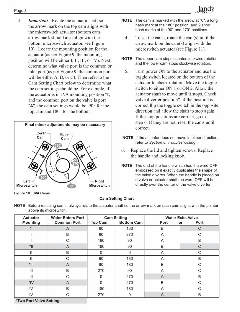
NOTE The cam is marked with the arrow at "0", a long hash mark at the 180° position, and 2 short hash marks at the 90° and 270° positions.
4. To set the cams, rotate the cam(s) until the arrow mark on the cam(s) align with the microswitch actuator (see Figure 11).
NOTE The upper cam stops counterclockwise rotation and the lower cam stops clockwise rotation.
5. Turn power ON to the actuator and use the toggle switch located on the bottom of the actuator to check rotation. Move the toggle switch to either ON 1 or ON 2. Allow the actuator shaft to move until it stops. Check valve diverter position*, if the position is correct flip the toggle switch in the opposite direction and allow the shaft to stop again. If the stop positions are correct, go to step 6. If they are not, reset the cams until correct.
NOTE If the actuator does not move in either direction, refer to Section 6, Troubleshooting.
6. Replace the lid and tighten screws. Replace the handle and locking knob.
NOTE The end of the handle which has the word OFF embossed on it exactly duplicates the shape of the valve diverter. When the handle is placed on a valve or actuator shaft the word OFF will be directly over the center of the valve diverter.
cam Setting chart
NOTE Before resetting cams, always rotate the actuator shaft so the arrow mark on each cam aligns with the pointer above its microswitch.
Actuator Mounting
Water Enters Portcommon Port
cam Setting Top cam bottom cam
Water Exits Valve Port or Port
*I A 90 180 B CI B 90 270 A CI C 180 90 A B
*II A 180 90 B CII B 0 0 A CII C 90 180 A B
*III A 90 180 B CIII B 270 90 A CIII C 0 270 A B*IV A 0 270 B CIV B 180 180 A CIV C 270 0 A B
*Two Port Valve Settings
3. Important - Rotate the actuator shaft so the arrow mark on the top cam aligns with the microswitch actuator (bottom cam arrow mark should also align with the bottom microswitch actuator, see Figure 10). Locate the mounting position for the actuator (as per Figure 9, the mounting position will be either I, II, III, or IV). Next, determine what valve port is the common or inlet port (as per Figure 9, the common port will be either A, B, or C). Then refer to the Cam Setting Chart below to determine what the cam settings should be. For example, if the actuator is in JVA mounting position "I", and the common port on the valve is port "A", the cam settings would be 90° for the top cam and 180° for the bottom.
Figure 10. JVA Cams
0
0
Right Microswitch
left Microswitch
Uppercam
Lowercam
Final minor adjustments may be necessary
0°
180°
270°
90°

Page 9
Section 4. Manual Operation
4.1 Manual Override
It is sometimes necessary to rotate a valve(s) without using the system controller. This occurs when the controller is not accessible/operational or when the spa or pool/spa combination require filling or draining.
There are two (2) methods of manually rotating the JVA; one with power on (system operational) and one with power off (no power to the control system).
4.2 Manual Override, Power On1. Move the toggle switch located on the
bottom of the actuator to the opposite position (ON 1 switch to ON 2 or vice versa). This will rotate the motor to the opposite position.
2. Return the toggle switch to the original position after use.
4.3 Manual Override, Power Off1. Move toggle switch located on the bottom
of actuator to the OFF (center) position.
2. Unscrew (counterclockwise) the locking knob above the handle four (4) full turns.
3. Push down on the locking knob (not the handle). This will disengage the gear train and allow the handle, and thus the valve diverter, to be moved to any position.
4. To return the actuator to automatic position, pull up on the handle while turning it clockwise or counterclockwise until you feel the shaft slide up into the gear train. Turn the locking knob down (clockwise) until snug.
5. Put toggle switch back to the original position.
cAUTIONTo prevent damage to your equipment and to minimize the possibility of any injury resulting from such damage, make sure that the pool filtration pump is OFF BEFORE rotating the valve handle.
ON 1
OFF
ON 2
Figure 12. JVA Synchronization, Toggle
On/Off Switch is on bottom of JVA
Figure 11. JVA Cam Adjustment
Rotate cams

Page 10
Section 5. Maintenance
5.1 Actuator
The JVA has three seals which should be lubricated once a year. One o-ring is located on the bottom of the actuator where the plastic shaft exits the housing and two (2) O-rings located in the top cover near where the shaft exits the top of the housing. Use the following steps to lubricate the seals:
1. Turn OFF power to the actuator.
2. Remove the locking knob and handle (see Figure 13).
7. Turn handle once around to spread the lubricant.
8. Pull up on the handle and tighten locking knob.
5.2 Valve
NOTE This section does not apply to Jandy NeverLube Valves and non-positive seal valves. NeverLube Valves and non-positive seal valves can be identified by the absence of a grease cap. NeverLube Valves can also be identified by the name "NeverLube" on the handle.
Since the actuator rotates the valve diverter which redirects the flow of water, it is imperative that the seals and the O-rings within the valve body be lubricated often (at least every three (3) months). Use the following procedure to lubricate the valve diverter seals:
1. Turn off all pool/spa equipment.
2. Rotate valve handle so the OFF on the handle is over the word GREASE on the valve body.
3. Unscrew (counterclockwise) and remove the black cap of the grease fitting.
4. Fill cap with lubricant (Jandy Lube).
5. Replace cap on fitting and turn in (clockwise) until all of the lubricant has been forced into the valve.
6. Use manual operation to move the handle from side to side to spread the lubricant across the seal.
7. Reset the valve handle to its original position and start the equipment.
Once a year the valve should be disassembled and the O-ring and valve body inspected for damage. Thoroughly lubricate the square seal and the O-ring. Reassemble the valve.
JVA2444
MAXIMUMTORQUE
Figure 13. JVA Shaft Seal
lubricate here
Unscrew Locking Knob and remove handle
3. Spread a small amount of Jandy Lube or other silicone base lubricant around the actuator shaft just above the lock out ring (see Figure 13).
4. Reinstall handle and locking knob. Only tighten knob one (1) turn.
5. Push down on the locking knob to force the actuator shaft into manual.
6. Wipe a small amount of lubricant around the actuator shaft where it protrudes from the bottom of the actuator.
Page 11
Section 6. Troubleshooting
6.1 Troubleshooting
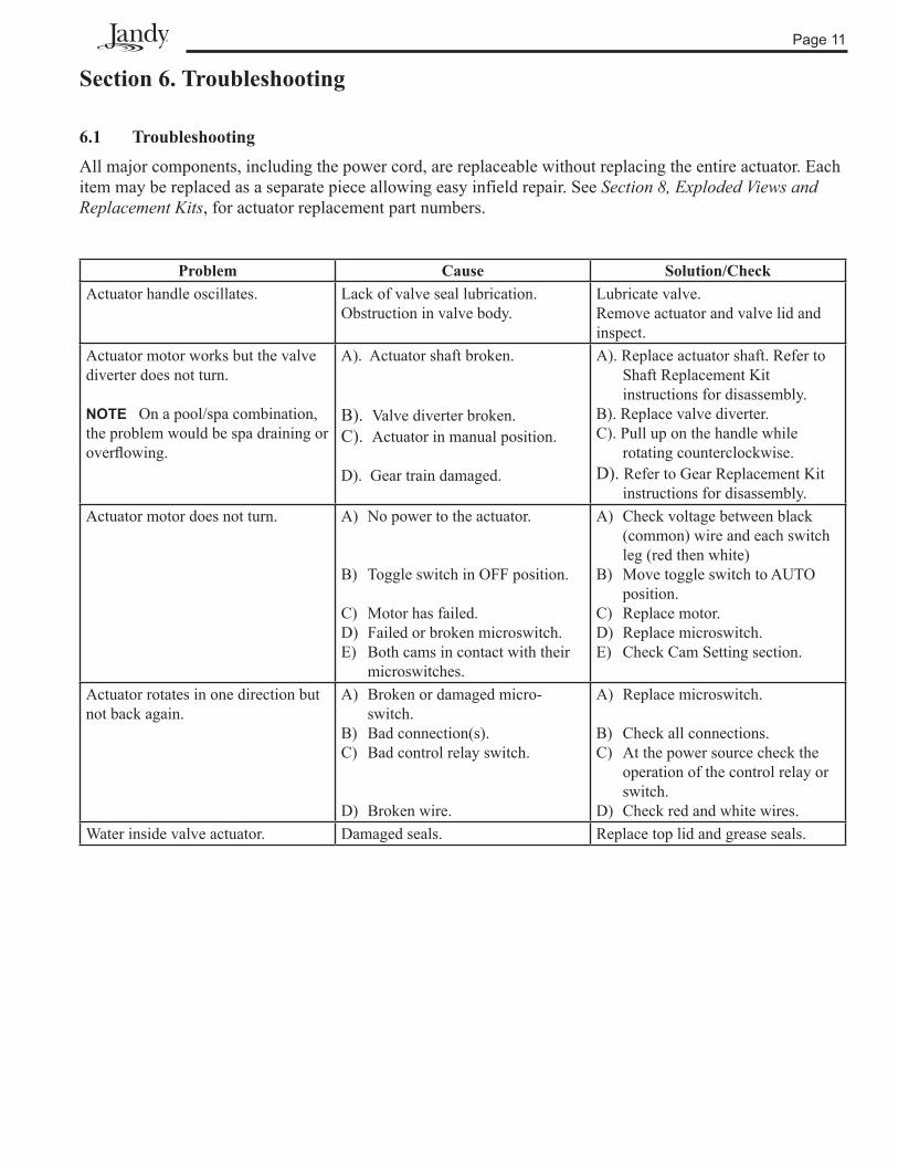
All major components, including the power cord, are replaceable without replacing the entire actuator. Each item may be replaced as a separate piece allowing easy infield repair. See Section 8, Exploded Views and Replacement Kits, for actuator replacement part numbers.
Problem Cause Solution/CheckActuator handle oscillates. Lack of valve seal lubrication.
Obstruction in valve body.Lubricate valve.Remove actuator and valve lid and inspect.
Actuator motor works but the valve diverter does not turn.
NOTE On a pool/spa combination, the problem would be spa draining or overflowing.
A). Actuator shaft broken.
B). Valve diverter broken.C). Actuator in manual position.
D). Gear train damaged.
A). Replace actuator shaft. Refer to Shaft Replacement Kit instructions for disassembly.
B). Replace valve diverter.C). Pull up on the handle while
rotating counterclockwise.D). Refer to Gear Replacement Kit
instructions for disassembly.Actuator motor does not turn. A) No power to the actuator.
B) Toggle switch in OFF position.
C) Motor has failed.D) Failed or broken microswitch.E) Both cams in contact with their microswitches.
A) Check voltage between black (common) wire and each switch leg (red then white)B) Move toggle switch to AUTO position.C) Replace motor.D) Replace microswitch.E) Check Cam Setting section.
Actuator rotates in one direction but not back again.
A) Broken or damaged micro- switch.B) Bad connection(s).C) Bad control relay switch.
D) Broken wire.
A) Replace microswitch.
B) Check all connections.C) At the power source check the operation of the control relay or switch.D) Check red and white wires.
Water inside valve actuator. Damaged seals. Replace top lid and grease seals.
Page 12
Section 7. Wiring Diagrams
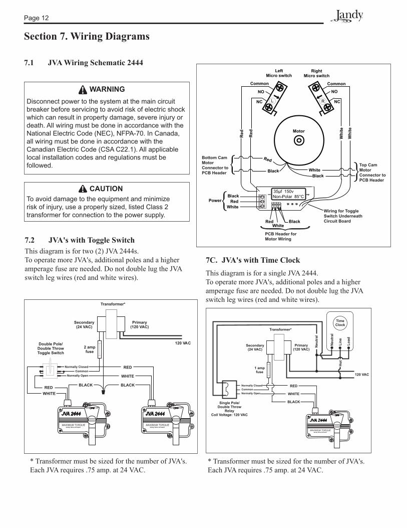
7.1 JVA Wiring Schematic 2444
7.2 JVA's with Toggle SwitchThis diagram is for two (2) JVA 2444s.To operate more JVA's, additional poles and a higher amperage fuse are needed. Do not double lug the JVA switch leg wires (red and white wires).
* Transformer must be sized for the number of JVA's. Each JVA requires .75 amp. at 24 VAC.
7C. JVA's with Time ClockThis diagram is for a single JVA 2444.To operate more JVA's, additional poles and a higher amperage fuse are needed. Do not double lug the JVA switch leg wires (red and white wires).
* Transformer must be sized for the number of JVA's. Each JVA requires .75 amp. at 24 VAC.
RED
WHITE
BLACK
OFF
JVA 2444
MAXIMUM TORQUEJandy Valve Actuator
Normally Closed
Normally Open
Common
1 amp
fuse120 VAC
Transformer*
Secondary
(24 VAC)
Primary
(120 VAC)
Single Pole/
Double Throw
Relay
Coil Voltage: 120 VAC
Neutral
Line
Load
Time
Clock
Neutral
Hot
Disconnect power to the system at the main circuit breaker before servicing to avoid risk of electric shock which can result in property damage, severe injury or death. All wiring must be done in accordance with the National Electric Code (NEC), NFPA-70. In Canada, all wiring must be done in accordance with the Canadian Electric Code (CSA C22.1). All applicable local installation codes and regulations must be followed.
WARNING
To avoid damage to the equipment and minimize risk of injury, use a properly sized, listed Class 2 transformer for connection to the power supply.
cAUTION
PCB Header forMotor Wiring
Wiring for ToggleSwitch UnderneathCircuit Board
Top CamMotorConnector toPCB Header
Bottom CamMotorConnector toPCB Header
OFF
JVA 2442444
RED
WHITE
BLACK
WHITE
BLACK
MAXIMUM TORQUEJandy Valve Actuator
OFF
JVA 2444
MAXIMUM TORQUEJandy Valve Actuator
Normally Closed
Normally OpenCommon
2 ampfuse
RED
120 VAC
Transformer*
Secondary(24 VAC)
Primary(120 VAC)
Double Pole/Double ThrowToggle Switch

Page 1�
Section 8. JVA Exploded View and Replacement KitsDwg.
#Kit # Description Qty.
1 R0�09600 JVA Gasket and Screw Kit
GasketO-ring, Screw, #1� x 2"Screw, #8 x 5/8"
12��
2 R0�11500 Top Housing Kit
GasketO-ringScrew, #8 x 5/8"Housing, Top
12�1
� R0�08700 Center Plate Kit
O-ringScrew, #8 x 5/8"BridgeTop Cam (Clear)Bottom Cam (Textured)MicroswitchCenter PlateOutput Shaft, ThreadedSpring, JVA
281112111
� R0�11600 Gear Kit
Primary GearSecondary GearLarge Pinion GearOutput GearHousing, Bottom w/� Pins
11111
5 R0�11800 Cable Kit, 20'
O-ring, Strain ReliefWasher, Strain ReliefCap, Strain ReliefPower Cord, 20' w/�-pin Connector
1111
5 R0�11900 Cable Kit, 75'
O-ring, Strain ReliefWasher, Strain ReliefCap, Strain ReliefPower Cord, 75' w/�-pin Connector
1111
6 R0��1700 PCB w/Toggle Switch Kit
PCB Sub-Assy, 2�V w/PCB, w/Toggle Switch, Lock Washer and Nut
1
7 R0�08500 Motor Kit
Screw, #8 x 5/8"Motor 2�V, w/Wire and Connector
11
8 R0�08600 Cam and Microswitch Kit
Top Cam (Clear)Bottom Cam (Textured)Microswitch
112
1
1, 2
2
1, 2
1, 2, 3 3
3, 7
3
7
6
3
3
4
4
3
3
3
3,8
5
3, 8
6
Page 1�
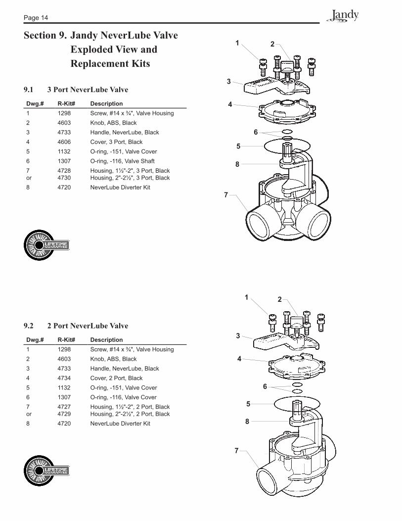
Section 9. Jandy NeverLube Valve Exploded View and Replacement Kits
9.1 3 Port NeverLube Valve
Dwg.# R-Kit# Description1 1298 Screw, #1� x ¾", Valve Housing2 �60� Knob, ABS, Black� �7�� Handle, NeverLube, Black� �606 Cover, � Port, Black5 11�2 O-ring, -151, Valve Cover6 1�07 O-ring, -116, Valve Shaft7or
�728�7�0
Housing, 1½"-2", � Port, BlackHousing, 2"-2½", � Port, Black
8 �720 NeverLube Diverter Kit
1
3
4
5
6
7
2
8
1
3
4
5
6
7
2
8
9.2 2 Port NeverLube Valve
Dwg.# R-Kit# Description1 1298 Screw, #1� x ¾", Valve Housing2 �60� Knob, ABS, Black� �7�� Handle, NeverLube, Black� �7�� Cover, 2 Port, Black5 11�2 O-ring, -151, Valve Cover6 1�07 O-ring, -116, Valve Cover7or
�727�729
Housing, 1½"-2", 2 Port, BlackHousing, 2"-2½", 2 Port, Black
8 �720 NeverLube Diverter Kit

Page 15
NOTES
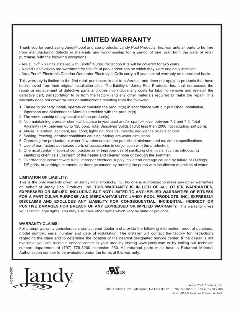
LIMITED WARRANTYThank you for purchasing Jandy® pool and spa products. Jandy Pool Products, Inc. warrants all parts to be freefrom manufacturing defects in materials and workmanship for a period of one year from the date of retail purchase, with the following exceptions:
• AquaLink® RS units installed with Jandy® Surge Protection Kits will be covered for two years.• NeverLube® valves are warranted for the life of pool and/or spa on which they were originally installed.• AquaPureTM Electronic Chlorine Generator Electrolytic Cells carry a 5 year limited warranty on a prorated basis.
This warranty is limited to the first retail purchaser, is not transferable, and does not apply to products that have been moved from their original installation sites. The liability of Jandy Pool Products, Inc. shall not exceed the repair or replacement of defective parts and does not include any costs for labor to remove and reinstall the defective part, transportation to or from the factory, and any other materials required to make the repair. This warranty does not cover failures or malfunctions resulting from the following:
1. Failure to properly install, operate or maintain the product(s) in accordance with our published Installation,Operation and Maintenance Manuals provided with the product(s).
2. The workmanship of any installer of the product(s).3. Not maintaining a proper chemical balance in your pool and/or spa [pH level between 7.2 and 7.8, Total
Alkalinity (TA) between 80 to 120 ppm, Total Dissolved Solids (TDS) less than 2000 not including salt ppm].4. Abuse, alteration, accident, fire, flood, lightning, rodents, insects, negligence or acts of God.5. Scaling, freezing, or other conditions causing inadequate water circulation.6. Operating the product(s) at water flow rates outside the published minimum and maximum specifications.7. Use of non-factory authorized parts or accessories in conjunction with the product(s).8. Chemical contamination of combustion air or improper use of sanitizing chemicals, such as introducing
sanitizing chemicals upstream of the heater and cleaner hose or through the skimmer.9. Overheating; incorrect wire runs; improper electrical supply; collateral damage caused by failure of O-Rings,
DE grids, or cartridge elements; or damage caused by running the pump with insufficient quantities of water.
LIMITATION OF LIABILITY:This is the only warranty given by Jandy Pool Products, Inc. No one is authorized to make any other warranties on behalf of Jandy Pool Products, Inc. THIS WARRANTY IS IN LIEU OF ALL OTHER WARRANTIES, EXPRESSED OR IMPLIED, INCLUDING BUT NOT LIMITED TO ANY IMPLIED WARRANTIES OF FITNESS FOR A PARTICULAR PURPOSE AND MERCHANTABILITY. JANDY POOL PRODUCTS, INC. EXPRESSLY DISCLAIMS AND EXCLUDES ANY LIABILITY FOR CONSEQUENTIAL, INCIDENTAL, INDIRECT OR PUNITIVE DAMAGES FOR BREACH OF ANY EXPRESSED OR IMPLIED WARRANTY. This warranty gives you specific legal rights. You may also have other rights which vary by state or province.
WARRANTY CLAIMS:For prompt warranty consideration, contact your dealer and provide the following information: proof of purchase, model number, serial number and date of installation. The installer will contact the factory for instructions regarding the claim and to determine the location of the nearest designated service center. If the dealer is not available, you can locate a service center in your area by visiting www.jandy.com or by calling our technical support department at (707) 776-8200 extension 260. All returned parts must have a Returned Material Authorization number to be evaluated under the terms of this warranty.
6000 Condor Drive • Moorpark, CA USA 93021 • 707.776.8200 • Fax 707.763.7785Litho in U.S.A. © Waterpik Technologies 0401
Jandy Pool Products, Inc.
Litho in U.S.A. © Jandy Pool Products, Inc. 0508
H05
7080
0C