
Installation and Operating Manual Integra 1560 and - Crompton
37
Installation and Operating Manual Integra 1560 and 1580 Digital Metering and Transducer Systems http://energy.tycoelectronics.com Energy Division Tyco Electronics UK Limited Crompton Instruments Freebournes Road, Witham, Essex, CM8 3AH, UK Tel: +44 1376 509 509 Fax: +44 1376 509 511
Transcript of Installation and Operating Manual Integra 1560 and - Crompton

Installation and Operating ManualIntegra 1560 and 1580Digital Metering and Transducer Systems
http://energy.tycoelectronics.comEnergy Division
Tyco Electronics UK LimitedCrompton InstrumentsFreebournes Road, Witham, Essex, CM8 3AH, UKTel: +44 1376 509 509 Fax: +44 1376 509 511

Crompton
Integra Digital Transducer
Installation & Operating Instructions
INT-1561, INT-1562, INT-1563, INT-1564,
INT-1581, INT-1582, INT-1583 and INT-1584
Crompton InstrumentsFreebournes Road
WithamEssex
CM8 3AHEngland
Tel: +44 (0) 1376 509 509Fax: +44 (0) 1376 509 511
E-Mail: [email protected]
Integra 1560, 1580 Issue 1 05/03

Contents Page
1 Introduction 5
2 Serial Communications 7
2.1. Port 1 – Display, Modbus or JC N2 7
2.2. Port 2 Option – Display or Modbus 7
2.3. Display auto detect 7
2.4. Communications Parameter Set Up 7
3 Modbus Implementation 8
4 Modbus Holding Registers and Transducer set up 11
5 RS485 Implementation of Johnson Controls Metasys 16
6 Pulsed Output Option 19
7 Analogue Output Option 19
8 Basis of measurement and calculations 20
8.1. Reactive and Apparent Power 20
8.2. Energy resolution 20
8.3. Power Factor 20
8.4. Maximum Demand 21
8.5. Total Harmonic Distortion 21
9 Specification 22
9.1. Inputs 22
9.2. Auxiliary 22
9.3. Measuring Ranges 23
9.4. Accuracy 23
9.5. Reference conditions of influence quantities 24
9.6. Range of Use 24
2 Integra 1560, 1580 Issue 1 05/03

Contents Page
9.7. Standards 25
9.8. Insulation 25
9.9. Environmental 25
9.10. Enclosure 26
9.11. Serial Communications Option 26
9.12. Active Energy Pulsed Output Option 26
9.13. Analogue Outputs Option 27
10 Metered Supply Connection Diagrams 28
11 Output Connections 30
12 Installation and Maintenance 30
12.1. Introduction 30
12.2. Electromagnetic Compatibility 31
12.3. Wiring 32
Metered Supply Input 32
Additional considerations for three wire systems 32
Output 32
Optional Display 33
Relay connections 33
12.4. Auxiliary Supply 33
12.5. Maintenance 34
Case Dimension 35
INT-1560 Case Dimensions – DIN Rail Mounting 35
INT-1580 Case Dimensions – Surface Mounting 35
Appendix A - CE Declaration of Conformity 36
3Integra 1560, 1580 Issue 1 05/03

1. Introduction
The Crompton Integra 1560/1580 is a measuring and communication module available withdigital, analogue or visual interfaces. Typically, it is used in conjunction with an Integra displayunit. When a permanent display is not required, the display can be temporarily connected for setup and system commissioning, and then disconnected. The Integra configuration software toolrunning on a Windows platform may also be used for set-up. Either communications port can beconnected to a display or to a Modbus master. One communications port also supports JohnsonControls NII protocol.
The Integra 1560/1580 will measure and communicate many electrical parameters, includingTHD values. All voltage and current measurements are True RMS for accurate measurement ofnon sinusoidal waveforms.
Not all configurations and options described in this manual may be immediately available.Contact your supplier for details of availability.
1560/1580 configurations and model numbers:
System DIN Rail Mounting Surface Mounting
Model No. Model No.
Single Phase 2 Wire INT-1562 INT-1582Single Phase 3 Wire INT-1561 INT-15813 Phase 3 Wire INT-1563 INT-15833 Phase 4 Wire INT-1564 INT-1584
The set up of the Integra 1560/1580 may be carried out by using the Crompton Integra displayunit or Integra configuration software – the user documentation gives more information on :
Configuring for use with installed current transformers
Setting Potential Transformer / Voltage Transformer ratios, where required
Demand Integration Time
Resetting demand and energy
Pulsed output set up
Communications (RS485) set up
Analogue output set up
Password protection of set up screens to prevent accidental modification
If required, most set up parameters may be manipulated directly via the Modbus interface.
Important safety information is contained in the Installation and Maintenance section.
Users must familiarise themselves with this information before attempting installation
or other procedures.
5Integra 1560, 1580 Issue 1 05/03

The parameters available from this Digital Transducer are listed in the table below.
Measured Quantity (Where applicable) Units of measurement
Voltage - Average, L1-L2, L2-L3, L3-L1, L1-N, L2-N & L3-N VoltsCurrent - Average & Individual Phases AmpsTotal Voltage Harmonic Distortion - Average & Individual Phases % of Total RMSTotal Current Harmonic Distortion - Average & Individual Phases % of Total RMSNeutral Current AmpsFrequency - System HzPower Factor - Average & Individual PhasesPower Factor - Inductive or Capacitive C or LPhase Angle - Average & Individual Phases DegreesActive Power - Sum & Individual Phases kW Reactive Power - Sum & Individual Phases kVar Apparent Power - Sum & Individual Phases kVA Active Energy - System kWhReactive Energy - System kvarhCurrent Demand - Total Amps dmdActive Power Demand - Total kW dmdMaximum Current Demand - Total Amps dmdMaximum Active Power Demand - Total kW dmd
Interfaces include:
• Display or RS485 Modbus RTU Port (standard)
• Second Modbus or Display Port (optional)
• One or two Energy Pulse Relays representing kWh and kvarh (optional)
• One Analogue Output Channel (optional)
• Second Analogue Output Channel (optional)
Connections for all interfaces are via detachable two-part screw clamp connectors.
6 Integra 1560, 1580 Issue 1 05/03
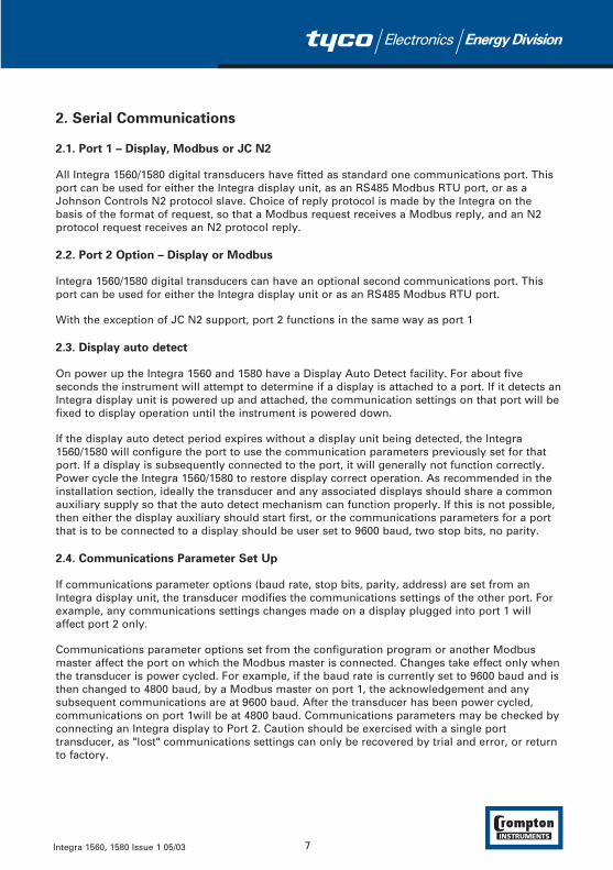
2. Serial Communications
2.1. Port 1 – Display, Modbus or JC N2
All Integra 1560/1580 digital transducers have fitted as standard one communications port. Thisport can be used for either the Integra display unit, as an RS485 Modbus RTU port, or as aJohnson Controls N2 protocol slave. Choice of reply protocol is made by the Integra on thebasis of the format of request, so that a Modbus request receives a Modbus reply, and an N2protocol request receives an N2 protocol reply.
2.2. Port 2 Option – Display or Modbus
Integra 1560/1580 digital transducers can have an optional second communications port. Thisport can be used for either the Integra display unit or as an RS485 Modbus RTU port.
With the exception of JC N2 support, port 2 functions in the same way as port 1
2.3. Display auto detect
On power up the Integra 1560 and 1580 have a Display Auto Detect facility. For about fiveseconds the instrument will attempt to determine if a display is attached to a port. If it detects anIntegra display unit is powered up and attached, the communication settings on that port will befixed to display operation until the instrument is powered down.
If the display auto detect period expires without a display unit being detected, the Integra1560/1580 will configure the port to use the communication parameters previously set for thatport. If a display is subsequently connected to the port, it will generally not function correctly.Power cycle the Integra 1560/1580 to restore display correct operation. As recommended in theinstallation section, ideally the transducer and any associated displays should share a commonauxiliary supply so that the auto detect mechanism can function properly. If this is not possible,then either the display auxiliary should start first, or the communications parameters for a portthat is to be connected to a display should be user set to 9600 baud, two stop bits, no parity.
2.4. Communications Parameter Set Up
If communications parameter options (baud rate, stop bits, parity, address) are set from anIntegra display unit, the transducer modifies the communications settings of the other port. Forexample, any communications settings changes made on a display plugged into port 1 willaffect port 2 only.
Communications parameter options set from the configuration program or another Modbusmaster affect the port on which the Modbus master is connected. Changes take effect only whenthe transducer is power cycled. For example, if the baud rate is currently set to 9600 baud and isthen changed to 4800 baud, by a Modbus master on port 1, the acknowledgement and anysubsequent communications are at 9600 baud. After the transducer has been power cycled,communications on port 1will be at 4800 baud. Communications parameters may be checked byconnecting an Integra display to Port 2. Caution should be exercised with a single porttransducer, as "lost" communications settings can only be recovered by trial and error, or returnto factory.
7Integra 1560, 1580 Issue 1 05/03

3. Modbus® Implementation
This section provides basic information for the integration of the product to a Modbus network.If background information or more details of the Integra implementation is required please referto our “Guide to RS485 Communications and the Modbus Protocol”, available on our CDcatalogue or from any recognised supplier.
Integra 1560/1580 offers the option of a RS485 communication facility for direct connection toSCADA systems using the Modbus‚ RTU protocol. The Modbus‚ protocol establishes the formatfor the master's query by placing into it the device address, a function code defining therequested action, any data to be sent, and an error checking field. The slave's response messageis also constructed using Modbus protocol. It contains fields confirming the action taken, anydata to be returned, and an error-checking field. If an error occurs in receipt of the message, or ifthe slave is unable to perform the requested action, the slave will construct an error messageand send it as it’s response.
The electrical interface is 2-wire RS485, via 3 screw terminals. Connection should be made usingtwisted pair screened cable (Typically 22 gauge Belden 8761 or equivalent). All "A" and "B"connections are daisy chained together. The screens should also be connected to the “Gnd”terminal. To avoid the possibility of loop currents, an Earth connection should be made at onlyone point on the network.
Line topology may or may not require terminating loads depending on the type and length ofcable used. Loop (ring) topology does not require any termination load.
The impedance of the termination load should match the impedance of the cable and be at bothends of the line. The cable should be terminated at each end with a 120 ohm (0.25 Watt min.)resistor.
A total maximum length of 3900 feet (1200 metres) is allowed for the RS485 network. Amaximum of 32 electrical nodes can be connected, including the controller.
The address of each Integra 1560/1580 can be set to any value between 1 and 247. Broadcastmode (address 0) is not supported.
The maximum latency time of an Integra 1560/1580 is 150ms i.e. this is the amount of time thatcan pass before the first response character is output. The supervisory programme must allowthis period of time to elapse before assuming that the Integra 1560/1580 is not going to respond.
The format for each byte in RTU mode is:
Coding System: 8-bit per byte
Data Format: 4 bytes (2 registers) per parameter.
Floating point format ( to IEEE 754)
Most significant register first (Default). The default may be changed if required - See Holding Register "Register Order" parameter.
8 Integra 1560, 1580 Issue 1 05/03

Error Check Field: 2 byte Cyclical Redundancy Check (CRC)
Framing: 1 start bit
8 data bits, least significant bit sent first
1 bit for even/odd parity or no parity
1 stop bit if parity is used; 1 or 2 bits if no parity
Data Transmission speed is selectable between 2400, 4800, 9600 and 19200 baud.
Input Registers
Input registers are used to indicate the present values of the measured and calculated electricalquantities.
Each parameter is held in two consecutive 16 bit registers. The following table details the 3Xregister address, and the values of the address bytes within the message. A tick (÷) in thecolumn indicates that the parameter is valid for the particular wiring system. Any parameterwith a cross (X) will return the value Zero (0000h).
Each parameter is held in the 3X registers. Modbus Function Code 04 is used to access allparameters.
e.g. to request Volts 1 Start address = 00
No of registers = 02
Volts 2 Start address = 02
No of registers = 02
Each request for data must be restricted to 40 parameters or less. Exceeding the 40 parameterlimit will cause a Modbus exception code to be returned.
9Integra 1560, 1580 Issue 1 05/03

Address Parameter Parameter Modbus Start 3 Ø 3 Ø 1 Ø 1 Ø
(Register) Number Address Hex 4 wire 3 wire 3 wire 2 wire
High Byte Low Byte
30001 1 Volts 1 (L1 – N 4W or L1 – L2 3W) 00 00
30003 2 Volts 2 (L2 – N 4W or L2 – L3 3W) 00 02 X30005 3 Volts 3 (L3 – N 4W or L3 – L1 3W) 00 04 X X30007 4 Current 1 00 06
30009 5 Current 2 00 08 X30011 6 Current 3 00 0A X X30013 7 W Phase 1 00 0C X
30015 8 W Phase 2 00 0E X X30017 9 W Phase 3 00 10 X X X30019 10 VA Phase 1 00 12 X
30021 11 VA Phase 2 00 14 X X30023 12 VA Phase 3 00 16 X X X30025 13 var Phase 1 00 18 X
30027 14 var Phase 2 00 1A X X30029 15 var Phase 3 00 1C X X X30031 16 Power Factor Phase 1 00 1E X
30033 17 Power Factor Phase 2 00 20 X X30035 18 Power Factor Phase 3 00 22 X X X30037 19 Phase Angle Phase 1 00 24 X
30039 20 Phase Angle Phase 2 00 26 X X30041 21 Phase Angle Phase 3 00 28 X X X30043 22 Volts Ave 00 2A
30047 24 Current Ave 00 2E
30049 25 Current Sum 00 30
30053 27 Watts Sum 00 34
30057 29 VA Sum 00 38
30061 31 var Sum 00 3C
30063 32 Power Factor Ave 00 3E
30067 34 Average Phase Angle 00 42
30071 36 Frequency 00 46
30073 37 Wh Import 00 48
30077 39 varh Import 00 4C
30085 43 W Demand Import 00 54
30087 44 W Max. Demand Import 00 56
30105 53 A Demand 00 68
30107 54 A Max. Demand 00 6A
30201 101 V L1-L2 (calculated) 00 C8 X X30203 102 V L2-L3 (calculated) 00 CA X X X30205 103 V L3-L1 (calculated) 00 CC X X X30207 104 Average Line to Line Volts 00 CE X X30225 113 Neutral Current 00 E0 X
30235 118 THD Volts 1 00 EA
30237 119 THD Volts 2 00 EC X30239 120 THD Volts 3 00 EE X X30241 121 THD Current 1 00 F0
30243 122 THD Current 2 00 F2 X30245 123 THD Current 3 00 F4 X X30249 125 THD Voltage Mean 00 F8
30251 126 THD Current Mean 00 FA
30255 128 Power Factor (+Ind/-Cap) 00 FE
10 Integra 1560, 1580 Issue 1 05/03

4. Modbus Holding Registers and Transducer set up
Holding registers are used to store and display instrument configuration settings. All holdingregisters not listed in the table below should be considered as reserved for manufacturer useand no attempt should be made to modify their values.
The demand parameters may be viewed or changed using the Modbus protocol. Each parameteris held in the 4X registers. Modbus Function Code 03 is used to read the parameter and FunctionCode 16 is used to write.
Address Parameter Parameter Modbus Start Valid range Mode
(Register) Number Address Hex
High Byte Low Byte
40001 1 Demand Time 00 00 0 only r/w40003 2 Demand Period 00 02 8,15,20,30 minutes. r/w40007 4 System Voltage 00 06 1V - 400kV r/wp40009 5 System Current 00 08 1-9999 A r/wp40011 6 System Type 00 0A ro40013 7 Relay Pulse Width 00 0C 3,5,10 (x20mS) r/w40015 8 Energy Reset 00 0E 0 only wo40019 10 RS485 set-up code * 00 12 See table below r/w40021 11 Node Address 00 14 1-247 r/w40023 12 Pulse Divisor 00 16 1,10,100,1000 r/w40025 13 Password 00 18 0000-9999 r/w40037 19 System Power 00 24 r/o40041 21 Register Order 00 28 2141.0 only wo40299 150 Secondary Volts 01 2A Min Vin-Max Vin r/wp40307 154 Max Energy Count 01 32 6,7,8 digits r/wp40309 155 Analogue Hardware Max 01 34 ro40311 156 Analogue Hardware Min 01 36 ro40313 157 Analogue 1 Output Parameter 01 38 See table below r/wp40315 158 Analogue 1 Parameter Max 01 3A ro40317 159 Analogue 1 Parameter Min 01 3C ro40319 160 Analogue 1 Reading Top 01 3E Analogue 1
Parameter Max r/wp40321 161 Analogue 1 Reading Bottom 01 40 Analogue 1
Parameter Min r/wp40323 162 Analogue 1 Output Top 01 42 Analogue Hardware
Max r/wp40325 163 Analogue 1 Output Bottom 01 44 Analogue Hardware
Min r/wp40329 165 Analogue 2 Output Parameter 01 48 See table below r/wp40331 166 Analogue 2 Parameter Max 01 4A ro40333 167 Analogue 2 Parameter Min 01 4C ro40335 168 Analogue 2 Reading Top 01 4E Analogue 2
Parameter Max r/wp40337 169 Analogue 2 Reading Bottom 01 50 Analogue 2
Parameter Min r/wp40339 170 Analogue 2 Output Top 01 52 Analogue Hardware
Max r/wp40341 171 Analogue 2 Output Bottom 01 54 Analogue Hardware
Min r/wp
r/w = read/write r/wp = read and write with password clearance ro = read only wo = write only
11Integra 1560, 1580 Issue 1 05/03

Password Settings marked r/wp require the instrument password to have been entered into thePassword register before changes will be accepted. Once the instrument configuration has beenmodified, the password should be written to the password register again to protect theconfiguration from unauthorised or accidental change. Power cycling also restores protection.Reading the Password register returns 1 if the instrument is unprotected and 0 if it is protectedfrom changes.
Demand Time is used to reset the demand period. A value of zero must be written to thisregister to accomplish this. Writing any other value will cause an error to be returned. Readingthis register after instrument restart or resetting demand period gives the number of minutes ofdemand data up to a maximum of the demand period setting. For example, with 15 minutedemand period, from reset the value will increment from zero every minute until it reaches 15. Itwill remain at this value until a subsequent reset occurs.
Demand Period The value written must be one of 8,15, 20 or 30, representing demand time inminutes. Writing any other value will cause an error to be returned.
System Voltage in a PT/VT connected system is the PT/VT primary voltage. In a direct connected(i.e. no PT.VT) system this parameter should be set the same as secondary volts.
System Current is the CT primary current.
System Type The System type address will display '1' for single phase 2 wire, '2' for 3 Phase 3Wire, '3' for 3 Phase 4 Wire or 4 for single phase 3 wire.
Relay Pulse Width is the width of the relay pulse in multiples of 20 ms. However, only values of3 (60 ms), 5 (100 ms) or 10 (200 ms) are supported. Writing any other value will cause an errorto be returned.
Reset Energy is used to reset the Energy readings. A value of zero must be written to thisregister to accomplish this. Writing any other value will cause an error to be returned.
RS485 Set-Up Code
Baud Rate Parity Stop Bits Decimal Value
19200 NONE 2 3019200 NONE 1 1419200 ODD 1 1319200 EVEN 1 129600 NONE 2 269600 NONE 1 109600 ODD 1 99600 EVEN 1 84800 NONE 2 224800 NONE 1 64800 ODD 1 54800 EVEN 1 42400 NONE 2 182400 NONE 1 22400 ODD 1 12400 EVEN 1 0
12 Integra 1560, 1580 Issue 1 05/03

Codes not listed in the table may give rise to unpredictable results including loss ofcommunication. Exercise caution when attempting to change mode via direct Modbus writes.Use of a display or the configuration program is recommended.
Node Address is the Modbus or JC N2 slave address for the instrument. Any value between 1and 247 can be set.
Pulse Rate Divisor, only values of 1,10,100 or 1000 are supported. Writing any other value willcause an error to be returned.
System Power, the maximum system power based on the values of system type, system voltsand system current.
Register Order, the instrument can receive or send floating-point numbers in normal or reversedregister order. In normal mode, the two registers that make up a floating point number are sentmost significant bytes first. In reversed register mode, the two registers that make up a floatingpoint number are sent least significant bytes first. To set the mode, write the value '2141.0' intothis register - the instrument will detect the order used to send this value and set that order forall Modbus transactions involving floating point numbers.
Secondary Volts indicates the voltage on the VT secondary when the voltage on the Primary isequal to the value of System Volts . The value of this register can be set to between theminimum and maximum instrument input voltage.
Maximum Energy Count, this controls the number of digits the energy (kWh and kvarh) counterscan use before they roll over (i.e. resets to zero). The values of 6, 7 or 8 can be written to thisregister to indicate the number of digits to use. Other values will be rejected.
Analogue Hardware Minimum and Analogue Hardware Maximum indicate respectively theminimum and maximum output currents that the instrument analogue output hardware iscapable of.
Analogue 1 Output Parameter, the number of the input parameter that is to be output onanalogue output 1. A value of zero signifies the analogue output is unused.
Analogue 1 Parameter Maximum, the maximum value that the selected input parameter canreach.
Analogue 1 Parameter Minimum, the minimum value that the selected input parameter canreach.
Analogue 1 Reading Top, the upper limit of the parameter value that will be output. This valuecan range between Parameter Minimum and Parameter Maximum.
Analogue 1 Reading Bottom, the lower limit of the parameter value that will be output. Thisvalue can range between Parameter Minimum and Parameter Maximum.
Analogue 1 Output Top, the analogue output level that will be achieved when the parameterreading reaches Reading Top. The value of Output Top must be between Analogue HardwareMinimum and Analogue Hardware Maximum.
Analogue 1 Output Bottom, the analogue output level that will be achieved when the parameterreading reaches Reading Bottom. The value of Output Bottom must be between AnalogueHardware Minimum and Analogue Hardware Maximum.
13Integra 1560, 1580 Issue 1 05/03

Analogue 2 set up values function in the same way as Analogue 1, except of course, they referto the second analogue channel.
Note: Analogue Hardware Maximum and Minimum refer to the factory build hardware limits. Itis the same for all analogue channels on a particular instrument.
Analogue Output Operation
When the values of Output Top is greater than Output Bottom, the analogue output will operatein a non-inverting mode. That is, when the selected metered value increases the analogueoutput will increase.
When the value of Output Top is less than Output Bottom, the analogue output will operate ininverting mode. That is, as the selected metered value increases the analogue output willdecrease. This can also be achieved by reversing Reading Top and Reading Bottom values.Reversing both will self cancel.
When the value of Reading Top is equal to Reading Bottom, the analogue output will operate inThreshold mode, the threshold being the value of Reading Top and Bottom. When the selectedmetered value rises above the threshold the analogue output will switch to Output Top. Whenthe selected metered value falls below the threshold the analogue output will switch to OutputBottom.
When Output Top is set to the same value as Output Bottom the analogue output will be fixed atthe specified value, effectively turning the output into a constant current generator.
The following parameters may be selected to be represented as analogue outputs. The rangesshown are the limit values for Reading Top and Reading Bottom.
14 Integra 1560, 1580 Issue 1 05/03

Parameter System Type
No. Name 3 Ø 4 wire 3 Ø 3 wire 1 Ø 3 wire 1 Ø 2 wire
1 Volts 1 0 – 1.2 * Vs 0 – 1.2 * Vs 0 – 1.2 * Vs 0 – 1.2 * Vs2 Volts 2 0 – 1.2 * Vs 0 – 1.2 * Vs 0 – 1.2 * Vs3 Volts 3 0 – 1.2 * Vs 0 – 1.2 * Vs4 Current 1 0 – 1.2 * Is 0 – 1.2 * Is 0 – 1.2 * Is 0 – 1.2 * Is5 Current 2 0 – 1.2 * Is 0 – 1.2 * Is 0 – 1.2 * Is6 Current 3 0 – 1.2 * Is 0 – 1.2 * Is7 W 1 ± 1.44 * Vs * Is ± 1.44 * Vs * Is ± 1.44 * Vs * Is8 W 2 ± 1.44 * Vs * Is ± 1.44 * Vs * Is9 W 3 ± 1.44 * Vs * Is10 VA 1 0 – 1.44 * Vs * Is 0 – 1.44 * Vs * Is 0 – 1.44 * Vs * Is11 VA 2 0 – 1.44 * Vs * Is 0 – 1.44 * Vs * Is12 VA 3 0 – 1.44 * Vs * Is13 var 1 ± 1.44 * Vs * Is ± 1.44 * Vs * Is ± 1.44 * Vs * Is14 var 2 ± 1.44 * Vs * Is ± 1.44 * Vs * Is15 var 3 ± 1.44 * Vs * Is16 Power Factor 1 ± 1 ± 1 ± 117 Power Factor 2 ± 1 ± 118 Power Factor 3 ± 119 Phase Angle 1 deg. ± 180 ± 180 ± 18020 Phase Angle 2 deg. ± 180 ± 18021 Phase Angle 3 deg. ± 18022 Voltage (Average) 0 – 1.2 * Vs 0 – 1.2 * Vs 0 – 1.2 * Vs 0 – 1.2 * Vs24 Current (Average) 0 – 1.2 * Is0 – 1.2 * Is 0 – 1.2 * Is 0 – 1.2 * Is25 Current (Sum) 0 – 3.6 * Is0 – 3.6 * Is 0 – 2.4 * Is 0 – 1.2 * Is27 W (Sum) ± 4.32 * Vs * Is ± 1.44 * ÷3 * Vs * Is ± 2.88 * Vs * Is ± 1.44 * Vs * Is29 VA (Sum) 0 – 4. 32 * Vs * Is 0 – 1.44 * ÷3 * Vs * Is0 – 2.88 * Vs * Is 0 – 1.44 * Vs * Is31 var (Sum) ± 4. 32 * Vs * Is ± 1.44 * ÷3 * Vs * Is ± 2.88 * Vs * Is ± 1.44 * Vs * Is32 Power Factor (Average) ± 1 ± 1 ± 1 ± 134 Phase Angle (Avg) deg. ± 180 ± 180 ± 180 ± 18036 Frequency Hz 40 – 70 40 – 70 0 – 70 40 – 7043 Import Power Demand 0 – 4. 32 * Vs * Is 0 – 1.44 * ÷3 * Vs * Is0 – 2.88 * Vs * Is 0 – 1.44 * Vs * Is44 Import Power Max. Dem. 0 – 4. 32 * Vs * Is 0 – 1.44 * ÷3 * Vs * Is0 – 2.88 * Vs * Is 0 – 1.44 * Vs * Is53 Current Demand 0 – 3.6 * Is0 – 3.6 * Is 0 – 2.4 * Is 0 – 1.2 * Is54 Current Max. Demand 0 – 3.6 * Is0 – 3.6 * Is 0 – 2.4 * Is 0 – 1.2 * Is101 Volts L1-L2 0 – 1.2 * ÷3 * Vs 0 – 2.4 * Vs102 Volts L2-L3 0 – 1.2 * ÷3 * Vs103 Volts L3-L1 0 – 1.2 * ÷3 * Vs104 Volts Line-Line (Avg) 0 – 1.2 * ÷3 * Vs 0 – 2.4 * Vs113 Neutral Current0 – 1.2 * Is 0 – 1.2 * Is 0 – 1.2 * Is118 THD Va % 0 – 100 0 – 100 0 – 100 0 – 100119 THD Vb % 0 – 100 0 – 100 0 – 100120 THD Vc % 0 – 100 0 – 100121 THD Ia % 0 – 100 0 – 100 0 – 100 0 – 100122 THD Ib % 0 – 100 0 – 100 0 – 100123 THD Ic % 0 – 100 0 – 100125 THD Voltage (Avg) % 0 – 100 0 – 100 0 – 100 0 – 100126 THD Current (Avg) % 0 – 100 0 – 100 0 – 100 0 – 100
Vs = System Volts, Is = System Current.
15Integra 1560, 1580 Issue 1 05/03

When analogue outputs are used to represent either individual or average power factor,parameters have slightly different meanings.
• The sign of the power factor when defining reading top and reading bottom is the sign of the active power : +ve for active power (watts) import and -ve for active power (watts) export.
• The reading span which the analogue output represents always includes unity (active power import, zero vars), but subject to this, the range span may be set as desired, using Reading Top and Reading Bottom.
• Reading Top value sets the limit value in the "export var" quadrants
• Reading Bottom value sets the limit value in the "import var" quadrants
• The direction the output moves depends on the Output Top and Output Bottom values.
• If Output Top is greater than Output Bottom, then the analogue output value increases as the power factor moves from the "export var" quadrants to the "import var" quadrants. This is the convention normally adopted in European technically influenced areas of the world.
• If Output Top is less than Output Bottom, then the analogue output value decreases as the power factor moves from the "export var" quadrants to the "import var" quadrants. This is the convention normally adopted in North American technically influenced areas of the world.
5. RS485 Implementation of Johnson Controls Metasys
Johnson Controls protocol implementation is only available on Port 1. Port 2 does not supportthis protocol. In a JC N2 protocol installation, typically port 2, where fitted, is used forinterfacing a display unit.
These notes explain Metasys and Crompton Instruments Integra 1560/1580 integration. Usethese notes with the Metasys Technical Manual, which provides information on installing andcommissioning Metasys N2 Vendor devices.
Application details
The Integra 1560/1580 is a N2 Vendor device that connects directly with the Metasys N2 Bus.This implementation assigns 33 key electrical parameters to ADF points, each with overridecapability.
Components requirements
• Integra 1560/1580 with RS485 card and Port 1 available.
• N2 Bus cable.
Metasys release requirements
• Metasys OWS software release 7.0 or higher.
• Metasys NCM311. NCM360.
16 Integra 1560, 1580 Issue 1 05/03

Support for Metasys Integration
Johnson Control SystemsSystem House, Randalls Research Park,Randalls Way, Leatherhead,Surrey, KT22 7TSEngland
Support for Crompton Integra operation
This is available via local sales and service centre.
Design considerations
When integrating the Crompton equipment into a Metasys Network, keep the followingconsiderations in mind.
• Make sure all Crompton equipment is set up, started and running properly before attempting to integrate with the Metasys Network.
• A maximum of 32 devices can be connected to any one NCM N2 Bus.
Vendor Address 1-247 (Limited by co-resident Modbus protocol)
Port Set-up
Baud Rate 9600
Duplex Full
Word Length 8
Stop Bits 1
Parity None
Interface RS485
17Integra 1560, 1580 Issue 1 05/03

METASYS N2 application
Integra 1560/1580 Point Mapping table
Address Parameter Description Units
1 Voltage 1 Volts2 Voltage 2 Volts3 Voltage 3 Volts4 Current 1 Amps5 Current 2 Amps6 Current 3 Amps7 Voltage average Volts8 Current average Amps9 Power (Watts) Sum Kwatts10 VA Sum kVA11 var Sum kvar12 Power Factor average13 Frequency Hz14 Active Energy (Import) kWh15 Reactive Energy (Import) kvarh16 Watts Demand (Import) kWatts17 Maximum Watts Demand (Import) kWatts18 Amps Demand Amps19 Maximum Amps Demand Amps20 Voltage L1-L2 (calculated) Volts21 Voltage L2-L3 (calculated) Volts22 Voltage L3-L1 (calculated) Volts23 Neutral Current Amps24 Active Energy (Import) GWh25 Reactive Energy (Import) Gvarh26 THD V1 %27 THD V2 %28 THD V3 %29 THD I1 %30 THD I2 %31 THD I3 %32 THD Vmean %33 THD Imean %
18 Integra 1560, 1580 Issue 1 05/03

6. Pulsed Output Option
One or two pulsed outputs are optionally available.
These relays output pulses at a rate proportional to the measured Active import Energy (kWh)and Reactive import Energy (kvarh).
The pulse width and pulse rate are both user definable via the Integra 1540 Display module orconfiguration program. See the relevant manual or Modbus Holding Register section of thisdocument for details.
The output relays provide fully isolated, volt free contacts and connection is made via screwclamp terminals.
7. Analogue Output Option
This module optionally provides one or two d.c. isolated outputs. These outputs can beindividually assigned to represent any one of the measured and displayed continuously variableparameters.
Output range limits are factory set as one of the options in the table below. The mA range forboth channels is the same.
Range Load Compliance Voltage
0/1mA 0-10kΩ 10V
0/5mA 0-2kΩ 10V
0/10mA 200W-1kΩ 10V
-1/0/+1mA 0-10kΩ 10V
-5/0/+5mA 0-2kΩ 10V
Parameters can be adjusted to suit the application and are not fixed to the system value. Topand bottom readings can be adjusted and a variety of outputs achieved, for example:
• Normal zero e.g. 0/1mA = 0/100kW
• Inverse zero e.g. 1mA/0 = 0/100kW
• Offset zero 0/1mA = 50/100kW
• Live zero 4-20mA = 0-100kW or 4-12-20mA = -100/0/+100kW
• Bipolar outputs, e.g. -1/0/+1mA = -100/0/+100kW
19Integra 1560, 1580 Issue 1 05/03
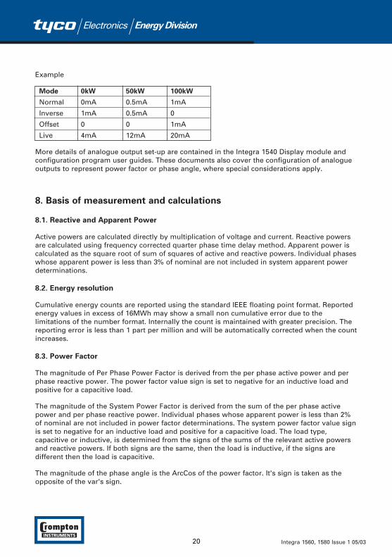
Example
Mode 0kW 50kW 100kW
Normal 0mA 0.5mA 1mA
Inverse 1mA 0.5mA 0
Offset 0 0 1mA
Live 4mA 12mA 20mA
More details of analogue output set-up are contained in the Integra 1540 Display module andconfiguration program user guides. These documents also cover the configuration of analogueoutputs to represent power factor or phase angle, where special considerations apply.
8. Basis of measurement and calculations
8.1. Reactive and Apparent Power
Active powers are calculated directly by multiplication of voltage and current. Reactive powersare calculated using frequency corrected quarter phase time delay method. Apparent power iscalculated as the square root of sum of squares of active and reactive powers. Individual phaseswhose apparent power is less than 3% of nominal are not included in system apparent powerdeterminations.
8.2. Energy resolution
Cumulative energy counts are reported using the standard IEEE floating point format. Reportedenergy values in excess of 16MWh may show a small non cumulative error due to thelimitations of the number format. Internally the count is maintained with greater precision. Thereporting error is less than 1 part per million and will be automatically corrected when the countincreases.
8.3. Power Factor
The magnitude of Per Phase Power Factor is derived from the per phase active power and perphase reactive power. The power factor value sign is set to negative for an inductive load andpositive for a capacitive load.
The magnitude of the System Power Factor is derived from the sum of the per phase activepower and per phase reactive power. Individual phases whose apparent power is less than 2%of nominal are not included in power factor determinations. The system power factor value signis set to negative for an inductive load and positive for a capacitive load. The load type,capacitive or inductive, is determined from the signs of the sums of the relevant active powersand reactive powers. If both signs are the same, then the load is inductive, if the signs aredifferent then the load is capacitive.
The magnitude of the phase angle is the ArcCos of the power factor. It's sign is taken as theopposite of the var's sign.
20 Integra 1560, 1580 Issue 1 05/03

8.4. Maximum Demand
The maximum power consumption of an installation is an important measurement as powerutilities often levy related charges. Many utilities use a thermal maximum demand indicator(MDI) to measure this peak power consumption. An MDI averages the power consumed over anumber of minutes, such that short surges do not give an artificially high reading.
Integra 1560/1580 uses a sliding window algorithm to simulate the characteristics of a thermalMDI instrument, with the demand period being updated every minute.
The demand period can be reset, which allows synchronisation to other equipment. When it isreset, the values in the Demand and Maximum Demand registers are set to zero.
Time Integration Periods can be set to 8, 15, 20 or 30 minutes
Note: During the initial period when the “sliding window” does not yet contain a full set ofreadings (i.e. the elapsed time since the demands were last reset or the elapsed time sinceIntegra 1560/1580 was switched on is less than the selected demand period) then maximumdemands may not be true due to the absence of immediate historical data.
The Time Integration Period can be user set either by using the Integra 1540 Display module orby using the communications option.
8.5. Total Harmonic Distortion
The calculation used for the Total Harmonic Distortion is:
THD = ((RMS of total waveform – RMS of fundamental) / RMS of total waveform) x 100
This is often referred to as THD – R
The figure is limited to the range 0 to 100% and is subject to the 'range of use' limits. Theinstrument may give erratic or incorrect readings where the THD is very high and thefundamental is essentially suppressed.
For low signal levels the noise contributions from the signal may represent a significant portionof the “RMS of total waveform” and may thus generate unexpectedly high values of THD. Toavoid indicating large figures of THD for low signal levels the product will produce a display of 0(zero). Typically, display of THD will only produce the 0 (zero) value when the THD calculationhas been suppressed due to a low signal level being detected.
It should also be noted that spurious signals (for example, switching spikes) if coincident withthe waveform sampling period will be included in the “RMS of the total waveform” and will beused in the calculation of THD. The display of THD may be seen to fluctuate under theseconditions.
21Integra 1560, 1580 Issue 1 05/03
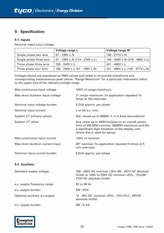
9. Specification
9.1. Inputs
Nominal rated input voltage
Voltage range L Voltage range M
Single phase two wire 57 - 139V L-N 140 - 277V L-N
Single phase three wire 57 - 139V L-N (114 - 278V L-L) 140 - 240V L-N (279 - 480V L-L)
Three phase three wire 100 - 240V L-L 241 - 480V L-L
Three phase four wire 100 - 240V L-L (57 - 139V L-N) 241 - 480V L-L (140 - 277V L-N)
Voltages above are expressed as RMS values and relate to sinusoidal waveforms andcorresponding instantaneous peak values. "Range Maximum" for a particular instrument refersto the upper end of the relevant voltage range.
Max continuous input voltage 120% of range maximum.
Max short duration input voltage 2* range maximum (1s application repeated 10 times at 10s intervals)
Nominal input voltage burden 0.2VA approx. per phase
Nominal input current 1 or 5A a.c. rms
System CT primary values Std. values up to 9999A (1 or 5 Amp secondaries)
System VT ratios Any value up to 400kV(subject to an overall power limit of 250 MW nominal, 360MW maximum and the4 significant digit limitation of the display unit, where this is used for setup)
Max continuous input current 120% of nominal
Max short duration current input 20* nominal (1s application repeated 5 times at 5 min intervals)
Nominal input current burden 0.6VA approx. per phase
9.2. Auxiliary
Standard supply voltage 100 - 250V AC nominal ±15% (85 - 287V AC absolute limits) or 100V to 250V DC nominal +25%, -15%(85 - 312V DC absolute limits)
a.c. supply frequency range 45 to 66 Hz
a.c. supply burden 3W / 6VA
Optional auxiliary d.c.supply 12 - 48V DC. nominal +25%, -15%(10.2 – 60VDC absolute limits)
d.c. supply burden 3W / 6 VA
22 Integra 1560, 1580 Issue 1 05/03
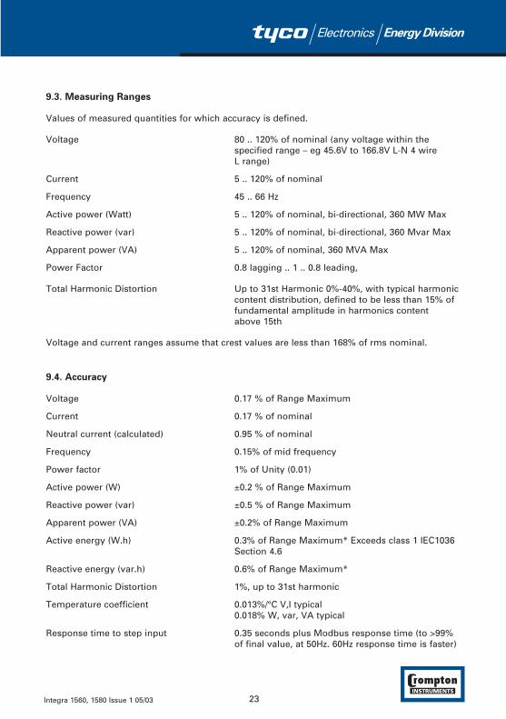
9.3. Measuring Ranges
Values of measured quantities for which accuracy is defined.
Voltage 80 .. 120% of nominal (any voltage within the specified range – eg 45.6V to 166.8V L-N 4 wire L range)
Current 5 .. 120% of nominal
Frequency 45 .. 66 Hz
Active power (Watt) 5 .. 120% of nominal, bi-directional, 360 MW Max
Reactive power (var) 5 .. 120% of nominal, bi-directional, 360 Mvar Max
Apparent power (VA) 5 .. 120% of nominal, 360 MVA Max
Power Factor 0.8 lagging .. 1 .. 0.8 leading,
Total Harmonic Distortion Up to 31st Harmonic 0%-40%, with typical harmonic content distribution, defined to be less than 15% of fundamental amplitude in harmonics content above 15th
Voltage and current ranges assume that crest values are less than 168% of rms nominal.
9.4. Accuracy
Voltage 0.17 % of Range Maximum
Current 0.17 % of nominal
Neutral current (calculated) 0.95 % of nominal
Frequency 0.15% of mid frequency
Power factor 1% of Unity (0.01)
Active power (W) ±0.2 % of Range Maximum
Reactive power (var) ±0.5 % of Range Maximum
Apparent power (VA) ±0.2% of Range Maximum
Active energy (W.h) 0.3% of Range Maximum* Exceeds class 1 IEC1036 Section 4.6
Reactive energy (var.h) 0.6% of Range Maximum*
Total Harmonic Distortion 1%, up to 31st harmonic
Temperature coefficient 0.013%/°C V,I typical0.018% W, var, VA typical
Response time to step input 0.35 seconds plus Modbus response time (to >99% of final value, at 50Hz. 60Hz response time is faster)
23Integra 1560, 1580 Issue 1 05/03
Error change due to variation of an 2 * Error allowed for the reference condition appliedinfluence quantity in the manner in the test. Error due to temperature variation as described in section 6 of IEC688:1992 above.
Error in measurement when a measurand 2 * Error allowed at the end of the reference is within its measuring range, but outside range adjacent to the section of the measuring its reference range. range where the measurand is currently operating /
being tested.
*Error in energy readings is expressed as a percentage of the energy count that would resultfrom applying range maximum voltage and nominal current for the same measurement period.
9.5. Reference conditions of influence quantities
Influence quantities are variables which affect measurement errors to a minor degree. Accuracyis verified under nominal value (within the specified tolerance) of these conditions.
Ambient temperature 23°±1°C
Input frequency 50 or 60 Hz ±2%
Input waveform Sinusoidal (distortion factor < 0.005)
Auxiliary supply voltage Nominal ±1%
Auxiliary supply frequency Nominal ±1%
Auxiliary supply (if AC) waveform Sinusoidal (distortion factor < 0.05)
Magnetic field of external origin Terrestrial flux
9.6. Range of Use
Values of measured quantities, components of measured quantities, and quantities which affectmeasurement errors to some degree, for which the product gives meaningful readings.
Voltage 5 .. 120% of Range Maximum (below 5% of Range Maximum voltage, current indication may be only approximate.)
Current 0.1 .. 120% of nominal
Frequency 45 .. 66 Hz
Power Factor 1 .. 0 leading or lagging(active/reactive as appropriate)
Active power (Watt) 1 .. 144% of nominal, 360MW Max
Reactive power (var) 1 .. 144% of nominal, 360Mvar Max
Apparent power (VA) 1 .. 144% of nominal, 360MVA Max
Harmonic distortion (voltage) Max 40% THD up to 31st harmonic
24 Integra 1560, 1580 Issue 1 05/03

Power is only registered when voltage and current are within their respective range of use.
Power Factor is only indicated when the measured VA is over 3% of Range Maximum.
Voltage THD is only indicated when the measured voltage is over 5% of Range Maximum, andfull accuracy only when measured voltage >25% of Range Maximum.
Current THD is only registered when the measured current is over 5% of nominal, and fullaccuracy only when measured current is over 20% of nominal
9.7. Standards
Terms, Definitions and Test Methods IEC688:1992 (BSEN 60688)
EMC Emissions EN61326 – Emission class A (Industrial)
EMC Immunity EN61326 – Immunity Annex A (Industrial)ANSI 39.90
Safety IEC1010-1 (BSEN 61010-1) Permanently connected use, Normal Condition Installation category III, pollution degree 2, Basic Insulation, for rated voltage.
9.8. Insulation
Dielectric voltage withstand test
• CT primary to voltage circuits 2.2kV RMS 50Hz for 1 minute
• Relay contact to voltage circuits 2.2kV RMS 50Hz for 1 minute
• RS485 to voltage circuits 3.1kV DC for 1 minute
• Analogue to voltage circuits 3.1kV DC for 1 minute
• Auxiliary supply to voltage circuits 2.7kV RMS 50Hz for 1 minute
• Base mounting to voltage circuits 2.2kV RMS 50Hz for 1 minute (Integra 1580 only)
CT primary to CT primary CT circuits are galvanically isolated from each other, resistance typically in excess of 100k ohms tested with a nominal voltage of 10VDC.
9.9. Environmental
Operating temperature -20 to +60°C*
Storage temperature -30 to +80°C*
Relative humidity 0 .. 90% non condensing
25Integra 1560, 1580 Issue 1 05/03

Warm up time 1 minute
Shock 30g in 3 planes
Vibration 10 .. 15 Hz, 1.5mm amplitude peak to peak,15Hz to 150 Hz @ 1g
*Maximum operating and storagetemperatures are in the context of typical daily and seasonal variation. These products are not designed for permanent operation or long term storage at maximum specified temperatures
9.10. Enclosure
1560 DIN rail 96x96mm Length < 125mm excluding terminations, plastic moulded case.
1580 Surface Mount steel plate 96x132mm Length < 125mm excluding terminations, plastic moulded case
9.11. Serial Communications Option
Baud rate 19200, 9600, 4800 or 2400 (programmable)
Parity None, Odd or Even, with 1 stop bit, or None with 2 stop bits.
Protocol MODBUS (RS 485) or Johnson Controls N2 Ver A 1996
(Note Johnson Controls N2 specifies fixed baud rate and parity)Programmable Modbus word order at user option.
9.12. Active Energy Pulsed Output Option
Default pulse rate 1 per kWhr
Pulse rate divisors 10 (yielding 1 pulse per 10 kWhr)100 (yielding 1 pulse per 100 kWhr)1000 (yielding 1 pulse per 1MWh)
Pulse duration 60ms, 100ms or 200ms3600 Pulses per Hour max
26 Integra 1560, 1580 Issue 1 05/03

Multiple Pulsed Output Option
Multiple pulsed option includes kWh import, kvarh import, Import relays are located on commscard
Default pulse rate 1 per kWhr, kvarh (all outputs have common scaling)
Pulse rate divisors 10 (yielding 1 pulse per 10 kWhr/ kvarh)100 (yielding 1 pulse per 100 kWhr/ kvarh)1000 (yielding 1 pulse per 1MWh/ Mvarh)
9.13. Analogue Outputs Option
Range
1 or 2 channels either 0/1mA0/5mA0/10mA0/20mA (user configurable as 4-20mA)-1/-0/+1mA-5/-0/+5mA
For 2 channel option both ranges must be identical.
27Integra 1560, 1580 Issue 1 05/03

10. Metered Supply Connection Diagrams
Connections shown are for predominantly importing applications. CT connections may bereversed for predominantly exporting applications, with a consequent reversal of signs forPower parameters.
European Style USA Style
3-PHASE - 4 WIRE UNBALANCED LOAD 3-PHASE - 4 WIRE UNBALANCED LOADDIGITAL METERING SYSTEM DIGITAL METERING SYSTEM
3-PHASE - 3 WIRE UNBALANCED LOAD 3-PHASE - 3 WIRE UNBALANCED LOADDIGITAL METERING SYSTEM DIGITAL METERING SYSTEM
28 Integra 1560, 1580 Issue 1 05/03

European Style USA Style
SINGLE PHASE - 2 WIRE SINGLE PHASE - 2 WIREDIGITAL METERING SYSTEM DIGITAL METERING SYSTEM
SINGLE PHASE - 3 WIRE SINGLE PHASE - 3 WIREDIGITAL METERING SYSTEM DIGITAL METERING SYSTEM
29Integra 1560, 1580 Issue 1 05/03

11. Output Connections
12. Installation and Maintenance
12.1. Introduction
Units should be installed in a dry position, where the ambient temperature is reasonably stableand will not be outside the range -20 to +60°C (55°C if optional outputs exceed two offcommunications ports). INT-1580 fixing should be by screws through the holes provided. INT-1560 fixing is direct to DIN Rail. Vibration should be kept to a minimum.
These units are intended for indoor use only at an altitude of less than 2000m.
Warning
• During normal operation, voltages hazardous to life may be present at some of the terminalsof this unit. Installation and servicing should be performed only by qualified, properly trained personnel' abiding by local regulations. Ensure all supplies are de-energised before attempting connection or other procedures.
• It is recommended adjustments be made with the supplies de-energised, but if this is not possible, then extreme caution should be exercised.
• Terminals should not be user accessible after installation and external installation provisionsmust be sufficient to prevent hazards under fault conditions.
• This unit is not intended to function as part of a system providing the sole means of fault protection - good engineering practice dictates that any critical function be protected by at least two independent and diverse means.
• Never open circuit the secondary winding of an energised current transformer.
30 Integra 1560, 1580 Issue 1 05/03

• Auxiliary circuits (12-48V auxiliary, communications, relay and analogue outputs, where applicable) are separated from metering inputs and 100-250V auxiliary circuits by at least basic insulation. Such auxiliary circuit terminals are only suitable for connection to equipment which has no user accessible live parts. The insulation for such auxiliary circuits must be rated for the highest voltage connected to the instrument and suitable for single fault condition. The connection at the remote end of such auxiliary circuits should not be accessible in normal use. Depending on application, equipment connected to auxiliary circuits may vary widely. The choice of connected equipment or combination of equipment should not diminish the level of user protection specified.
• This unit is not intended to provide safety rated isolation between the 12-48V auxiliary terminals and communications or analogue output circuits. Galvanic isolation is provided, but one of the 12-48V inputs should be at or near earth potential.
• The metal base plate on the Integra 1580 must be earthed.
12.2. Electromagnetic Compatibility
This unit has been designed to provide protection against EM (electro-magnetic) interference inline with requirements of EU and other regulations. Precautions necessary to provide properoperation of this and adjacent equipment will be installation dependent and so the following canonly be general guidance:-
• Avoid routing wiring to this unit alongside cables and products that are, or could be, a source of interference.
• The auxiliary supply to the unit should not be subject to excessive interference. In some cases, a supply line filter may be required.
• To protect the product against incorrect operation or permanent damage, surge transients must be controlled. It is good EMC practice to suppress differential surges to 2kV or less at the source. The unit has been designed to automatically recover from typical transients, however in extreme circumstances it may be necessary to temporarily disconnect the auxiliary supply for a period of greater than 5 seconds to restore correct operation.
• Screened communication and small signal leads are recommended and may be required. These and other connecting leads may require the fitting of RF suppression components, such as ferrite absorbers, line filters etc., if RF fields cause problems.
• It is good practice to install sensitive electronic instruments that are performing critical functions in EMC enclosures that protect against electrical interference causing a disturbance in function.
31Integra 1560, 1580 Issue 1 05/03

12.3. Wiring
Metered Supply Input
Input connections are made to screw clamp terminals. Choice of cable should meet localregulations for the operating voltage and current. Terminals for both current and voltage inputswill accept one or two 3mm2 or less cross sectional area cables. This unit must be fitted withexternal fuses in voltage and auxiliary supply lines. Voltage input lines must be fused with aquick blow AC fuse 1A maximum. Auxiliary supply lines must be fused with a slow blow fuserated 1A maximum. Choose fuses of a type and with a breaking capacity appropriate to thesupply and in accordance with local regulations.
Where fitted, CT secondaries must be grounded in accordance with local regulations. It isdesirable to make provision for shorting links to be made across CTs. This permits easyreplacement of a unit should this ever be necessary.
A switch or circuit breaker allowing isolation of supplies to the unit must be provided.
Main terminal screws should be tightened to 1.35Nm or 1.0 ft/lbf only.
Additional considerations for three wire systems
If this product is used in a system with an a.c. auxiliary where the frequency of the auxiliary maybe different to the frequency of the signals being measured it will be necessary to connect theneutral terminal (terminal number 11) either to the system neutral connection or to an earth(ground) connection in order to achieve the published specifications.
The neutral terminal (terminal number 11) is indirectly connected to the voltage input terminals(terminals 2, 5 and 8). When connected to a three wire system where one of the lines hasbecome disconnected the neutral terminal will adopt a potential somewhere between theremaining lines.
If external wiring is connected to the neutral terminal it must be connected to either the neutralline or earth (ground) to avoid the possibility of electric shock from the neutral terminal.
Standard CT wiring configurations for 3 wire systems include a commoning point. A maximumof two units, fed from a single set of CTs and with a single earth point may be wired in this way.If more units must be run from a single set of CTs then use 3 CTs and wire CT connections asfor 4 wire systems. In this configuration, the number of units that may be connected is limitedby the permissible CT burden.
Output
Output connections are made directly to a two part, detachable screw clamp style connector.The choice of cable should satisfy local regulations for the operating voltage and current. This isparticularly important for the relay contact wiring which may carry potentially hazardousvoltages.
Detachable terminal connector screws should be tightened to 0.9Nm or 0.7 ft/lbf only.
32 Integra 1560, 1580 Issue 1 05/03

Optional Display
The connections between the optional display and transducer are made directly to two-partdetachable screw clamp style connectors. The recommended cable between the display andtransducer is two core screened cable. Preferably select a cable specifically recommended forRS485 use (for example Belden 9860, 8761) although for shorter distances of a few metres mosttwo core screened cables will often be satisfactory. The display to transducer communicationuses RS485 and therefore cable length (transmission distance) can be up to 1200 metres in goodconditions. Electrical interference or other adverse conditions may reduce the maximum cablelength possible for reliable operation.
Relay connections
When the centre output connector is fitted, Relay 2 and Relay 3 provide output pulses withchange over contacts. When only a single pulsing relay is specified, the 6 way Relay 2 / Relay 3connector shown on the diagram in section 11 may not be fitted. On this variant, Relay 1normally open contacts are available on the main terminal block at terminals 13 and 14 asshown on the wiring diagrams in section 10.
12.4. Auxiliary Supply
There are two auxiliary options available as factory build options. The auxiliary supply is markedon the unit rating label. The Integra 1560/1580 should ideally be powered from a dedicatedsupply, however when the 100-250 V auxiliary option is fitted it may be powered from the signalsource, providing the source remains within tolerance of the medium voltage auxiliary range.
The auxiliary supply connection has terminals for both medium voltage and low voltageauxiliary. Depending on the supply option fitted either the 12-48 pair or the 100-250v pair will beoperational. For 100-250 V auxiliary, connect the supply to the outer two terminals marked L andN. For 100-250 V, connections are polarity insensitive. For 12-48 V auxiliary, connect to centreand right hand (as viewed from instrument rear) terminals marked - and +. Polarity reversal willnot cause damage but the instrument will not function.
100-250V AC 100-250V ACor DC or DC
O N - L+ O
12-48V 12-48V negative Positive
It is recommended that when used with an Integra 1540 display, a common auxiliary supply isused for both the display and transducer. If this arrangement is not implemented then thetransducer communications parameters may be configured as detailed in the preceding section"Serial Communications". The transducer establishes contact with a display in the first 5 secondsafter power up, and may not operate correctly with the display if the display is powered severalseconds after the transducer is powered, unless the communications parameters are setappropriately.
33Integra 1560, 1580 Issue 1 05/03

12.5. Maintenance
In normal use, little maintenance is needed. As appropriate for service conditions, isolateelectrical power, inspect the unit and remove any dust or other foreign material present.Periodically check all connections for freedom from corrosion and screw tightness, particularly ifvibration is present.
If necessary wipe the case with a dry cloth. If a cleaning agent is necessary, isopropyl alcohol isthe only recommended agent and should be used sparingly. Water should not be used. If thecase exterior or terminals should accidentally be contaminated with water, the unit must bethoroughly dried before further service. Should it be suspected that water might have enteredthe unit, factory inspection and refurbishment is recommended.
In the unlikely event of a repair being necessary, it is recommended that the unit be returned tothe factory or nearest Crompton service centre.
34 Integra 1560, 1580 Issue 1 05/03
35Integra 1560, 1580 Issue 1 05/03
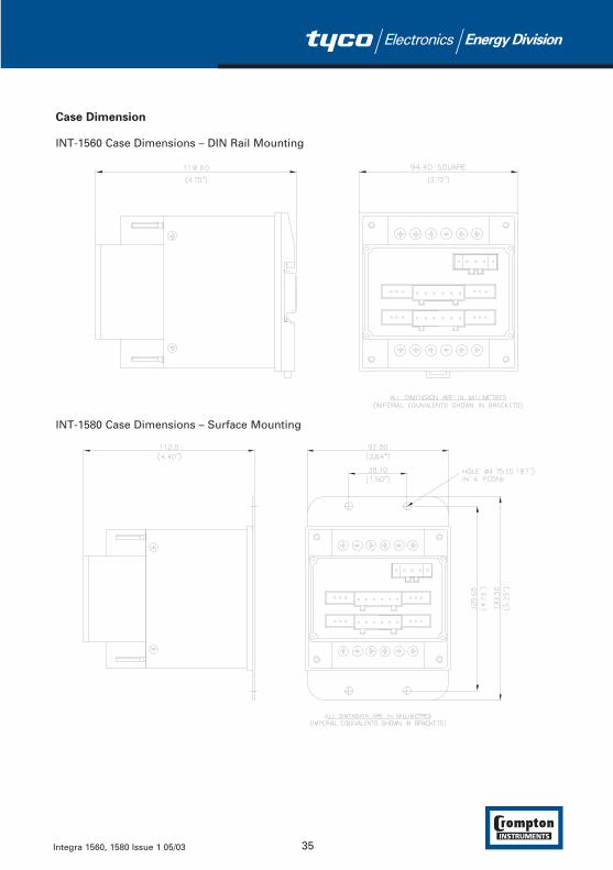
Case Dimension
INT-1560 Case Dimensions – DIN Rail Mounting
INT-1580 Case Dimensions – Surface Mounting

36 Integra 1560, 1580 Issue 1 05/03

http://energy.tycoelectronics.com
Tyco Electronics UK LimitedCrompton InstrumentsFreebournes Road, Witham, Essex, CM8 3AH, UKTel: +44 1376 509 509 Fax: +44 1376 509 511
The Information contained in these installation instructions is for use only by installers trained to make electrical power installations and is intendedto describe the correct method of installation for this product. However, Tyco Electronics has no control over the field conditions which influenceproduct installation. It is the user's responsibility to determine the suitability of the installation method in the user's field conditions. Tyco Electronics' only obligationsare those in Tyco Electronics' standard Conditions of Sale for this product and in no case will Tyco Electronics be liable for any other incidental,indirect or consequential damages arising from the use or misuse of the products. Crompton is a trade mark.