Installation and Operating Manual - Voithvoith.com/corp-en/1321_e_3626-011700_en_rev.9.pdf ·...
126
Installation and Operating Manual (Translation of the original installation and operating manual) T… (with GPK) Turbo Coupling with Constant Fill, Connecting Coupling Type GPK (All-metal Disk Pack Coupling) including design as per ATEX directives: Directive 94/9/EC (valid until April 19, 2016), Directive 2014/34/EU (valid from April 20, 2016) Version 9 , 2016-01-11 3626-011700 en, Protection Class 0: public Serial No. 1) Coupling type 2) Year of manufacture Mass (weight) kg Power transmission kW Input speed rpm Operating fluid mineral oil water Filling volume dm 3 (liters) Number of screws z 3) Nominal response temperature of fusible plugs °C Connecting coupling type GPK Sound pressure level L PA,1m dB Installation position horizontal (max. 7°) Drive via outer wheel 1) Please indicate the serial number in any correspondence ( Chapter 18). 2) T...: oil / TW...: water. 3) Determine and record the number of screws z ( Chapter 10.1). Please consult Voith Turbo in case that the data on the cover sheet are incomplete.
Transcript of Installation and Operating Manual - Voithvoith.com/corp-en/1321_e_3626-011700_en_rev.9.pdf ·...

Installation and Operating Manual (Translation of the original installation and operating manual)
T… (with GPK) Turbo Coupling with Constant Fill, Connecting Coupling Type GPK (All-metal Disk Pack Coupling) including design as per ATEX directives: Directive 94/9/EC (valid until April 19, 2016), Directive 2014/34/EU (valid from April 20, 2016)
Version 9 , 2016-01-11 3626-011700 en, Protection Class 0: public
Serial No. 1)
Coupling type 2)
Year of manufacture Mass (weight) kg Power transmission kW Input speed rpm
Operating fluid mineral oil water
Filling volume dm3 (liters) Number of screws z 3)
Nominal response temperature of fusible plugs
°C
Connecting coupling type GPK Sound pressure level LPA,1m dB Installation position horizontal (max. 7°) Drive via outer wheel
1) Please indicate the serial number in any correspondence ( Chapter 18).2) T...: oil / TW...: water.3) Determine and record the number of screws z ( Chapter 10.1).
Please consult Voith Turbo in case that the data on the cover sheet are incomplete.

Inst
alla
tion
and
Ope
ratin
g M
anua
l / V
ersi
on 9
/ 36
26-0
1170
0 en
/ Pr
otec
tion
Cla
ss 0
: pub
lic /
2016
-01-
11
2
Turbo Coupling with constant fill (Connecting Coupling Type GPK) Contact
Contact
Voith Turbo GmbH & Co. KG Division Mining & Metals Voithstr. 1 74564 Crailsheim, GERMANY Tel. + 49 7951 32 409 Fax + 49 7951 32 480 [email protected] www.voith.com/fluid-couplings
3626-011700 en This document describes the state of design of the product at the time of the editorial deadline on 2016-01-11. Copyright © by Voith Turbo GmbH & Co. KG. This document is protected by copyright. It must not be translated, duplicated (mechanically or electronically) in whole or in part, nor passed on to third parties without the publisher's written approval.

Inst
alla
tion
and
Ope
ratin
g M
anua
l / V
ersi
on 9
/ 36
26-0
1170
0 en
/ Pr
otec
tion
Cla
ss 0
: pub
lic /
2016
-01-
11
3
Turbo Coupling with constant fill (Connecting Coupling Type GPK) Contents
Contents 1 Voith Turbo Coupling with Constant Fill 7
1.1 Function 7
1.2 Type designation 9
1.3 Constructional examples 10
2 Technical data 14
3 Tightening torques 16
3.1 Set screws 18
3.2 Fusible plugs, filler plugs, sight glasses, blind- and nozzle screws 18
3.3 Fastening screws 19
4 Declarations of Manufacturer 20
4.1 Declaration regarding assemblies and components 20
4.2 Conformity Declaration 21
5 User information 22
6 Safety 24
6.1 Safety information 24 6.1.1 Structure of safety information 24 6.1.2 Definition of safety symbols 25
6.2 Intended use 25
6.3 Unintended use 26
6.4 Structural modifications 26
6.5 General information as to dangerous situations 26
6.6 Remaining risks 31
6.7 What to do in case of accidents 31
6.8 Information with regard to operation 31
6.9 Qualification of staff 35
6.10 Product monitoring 35
Inst
alla
tion
and
Ope
ratin
g M
anua
l / V
ersi
on 9
/ 36
26-0
1170
0 en
/ Pr
otec
tion
Cla
ss 0
: pub
lic /
2016
-01-
11
4
Turbo Coupling with constant fill (Connecting Coupling Type GPK) Contents
7 Transport and Storage 36
7.1 As delivered condition 36
7.2 Scope of supply 36
7.3 Transport 37
7.4 Lifting 38
7.5 Storage / Packing / Preservation 44
8 Installation and alignment 46
8.1 Functioning of GPK (all-metal disk pack coupling) 46
8.2 Tools 47
8.3 Preparation 48 8.3.1 Keys 49
8.4 Mounting the input hub and output hub 50 8.4.1 Preconditions 51
8.5 Mounting and alignment of GPK, version without clamping hub 52 8.5.1 Mounting the input hub and output hub 52 8.5.2 Alignment 53 8.5.3 Turbo coupling installation 57 8.5.4 Check of alignment 59
8.6 Mounting and alignment of GPK-XP, version with clamping hub 61 8.6.1 Mounting the input hub and output hub 61 8.6.2 Alignment 62 8.6.3 Preparatory work on clamping hub and plug-in shaft 66 8.6.4 Turbo coupling installation 67 8.6.5 Check of alignment 69
9 Operating fluids 71
9.1 Requirements to be fulfilled by the operating fluid 'mineral oil' 72 9.1.1 Usable operating fluids 72 9.1.2 Operating temperature frequently above 100 °C 72 9.1.3 Proposed operating fluids 73

Inst
alla
tion
and
Ope
ratin
g M
anua
l / V
ersi
on 9
/ 36
26-0
1170
0 en
/ Pr
otec
tion
Cla
ss 0
: pub
lic /
2016
-01-
11
5
Turbo Coupling with constant fill (Connecting Coupling Type GPK) Contents
9.2 Proposed operating fluids for special requirements 74
9.3 Requirements to be fulfilled by the operating fluid 'water' 75 9.3.1 Usable operating fluids 75 9.3.2 Water used as operating fluid for turbo couplings with centrifugal valves (types TW…F…) 76
10 Filling, Filling Check and Draining 78
10.1 Filling the turbo coupling 79
10.2 Level check 80
10.3 Draining the turbo coupling 80 10.3.1 Draining of turbo couplings without delay chamber installed in horizontal position 81 10.3.2 Draining of turbo couplings with delay chamber installed in horizontal position 81
11 Commissioning 82
12 Operation 85
13 Maintenance, Servicing 86
13.1 Outside cleaning 89
13.2 Connecting coupling types GPK and GPK-XP 90
13.3 Bearings 90 13.3.1 Bearing lubrication when mineral oil is used as operating fluid 90 13.3.2 Bearing lubrication when water is used as operating fluid 91 13.3.3 Replacement of bearings / re-lubrication 91
13.4 Fusible plugs 91 13.4.1 Fusible plugs in turbo couplings not suitable for use in potentially explosive atmospheres 92 13.4.2 Fusible plugs in turbo couplings suitable for use in potentially explosive atmospheres 94
14 Assembly Check-, Commissioning and Maintenance Report 96
14.1 Assembly check report 97
14.2 Commissioning report 99
14.3 Maintenance report for general maintenance 101

Inst
alla
tion
and
Ope
ratin
g M
anua
l / V
ersi
on 9
/ 36
26-0
1170
0 en
/ Pr
otec
tion
Cla
ss 0
: pub
lic /
2016
-01-
11
6
Turbo Coupling with constant fill (Connecting Coupling Type GPK) Contents
15 Disassembly of Turbo Coupling 102
15.1 Preparation 102
15.2 Disassembly of type GPK (without clamping hub) 103
15.3 Reassembly of type GPK (without clamping hub) 103
15.4 Disassembly of type GPK-XP (with clamping hub) 103
15.5 Reassembly of type GPK-XP (with clamping hub) 103
16 Disposal 104
17 Malfunctions - Remedial Actions 105
18 Queries, Orders Placed for Service Engineers and Spare Parts 107
19 Temperature monitoring 108
19.1 MTS mechanical thermal switch unit for pre-warning 109
19.2 BTS non-contacting thermal switch unit 110 19.2.1 BTS non-contacting thermal switch unit for pre-warning 110 19.2.2 BTS-Ex non-contacting thermal switch unit for limiting the maximum surface temperature 111
19.3 BTM non-contacting thermal measuring device for pre-warning 112
20 Spare parts information 113
20.1 Components overview - Voith turbo coupling 366 – 1150 114
20.2 Spare parts for Voith turbo coupling 366 – 1150 115
20.3 Spare parts for connecting coupling type GPK (without clamping hub) 117
20.4 Spare parts for connecting coupling type GPK-XP (with clamping hub) 118
21 Representatives - Voith Turbo GmbH & Co. KG 119
22 Index 124

Inst
alla
tion
and
Ope
ratin
g M
anua
l / V
ersi
on 9
/ 36
26-0
1170
0 en
/ Pr
otec
tion
Cla
ss 0
: pub
lic /
2016
-01-
11
7
Turbo Coupling with constant fill (Connecting Coupling Type GPK) Voith Turbo Coupling with Constant Fill
1 Voith Turbo Coupling with Constant Fill
1.1 Function
Fig. 1 The Voith turbo coupling is a hydrodynamic coupling working to the Föttinger principle. Its main elements consist of two blade wheels - the pump impeller and the turbine wheel - enclosed by a shell. Both wheels are provided with bearings relative to each other. The power is transmitted with hardly any wear, there is no mechanical contact between the power-transmitting parts. A constant amount of operating fluid is in the coupling. The mechanical energy provided by the drive motor is converted into kinetic energy of the operating fluid in the connected pump impeller. In the turbine wheel, this kinetic energy is reconverted into mechanical energy.
Shell Blade wheels

Inst
alla
tion
and
Ope
ratin
g M
anua
l / V
ersi
on 9
/ 36
26-0
1170
0 en
/ Pr
otec
tion
Cla
ss 0
: pub
lic /
2016
-01-
11
8
Turbo Coupling with constant fill (Connecting Coupling Type GPK) Voith Turbo Coupling with Constant Fill
Three conditions are to be considered with regard to the coupling function:
Fig. 2
Standstill The whole operating fluid rests in the coupling.
Fig. 3
Starting condition The pump impeller accelerates the operating fluid with increasing motor speed causing a circulating flow in the working chamber. The whole blade space of the turbine wheel is flooded, and the turbine wheel starts to move as a result of the kinetic energy of the fluid flow. The coupling characteristic curve determines the torque curve during start-up.
Fig. 4
Nominal operation During nominal operation, only the torque required by the driven machine is trans-mitted. The low speed difference between pump impeller and turbine wheel (the so-called rated slip) results in a stationary flow condition in the coupling.

Inst
alla
tion
and
Ope
ratin
g M
anua
l / V
ersi
on 9
/ 36
26-0
1170
0 en
/ Pr
otec
tion
Cla
ss 0
: pub
lic /
2016
-01-
11
9
Turbo Coupling with constant fill (Connecting Coupling Type GPK) Voith Turbo Coupling with Constant Fill
1.2 Type designation For hydrodynamic couplings with constant fill, connecting coupling type: GPK, the type designation is determined as follows:
1 2 3 4 5 6 7 8 9 10 11
Example: 562 TVVSC
562 T VV S C
1 Coupling size (profile diameter in mm) Possible sizes: 366, 422, 487, 562, 650, 750, 866, 1000, 1150
2 Number of hydrodynamic circuits T: single-circuit coupling DT: double-circuit coupling
3 Material "no code letter": Silumin U: ferrous material
4 Operating fluid "no code letter": mineral oil W: water (please consult Voith regarding anti-freezing agent)
5 Delay chamber "no code letter": without delay chamber V: with delay chamber VV: with enlarged delay chamber
6 Draining of delay chamber "no code letter": time-dependent draining without dynamic refill F: with centrifugal valves (normally they are open on standstill) Y: with dynamic refill
7 Shell "no code letter" standard design S: designed as annular chamber
8 Design status “no code letter“: first design old: A, B, C, E, G, H, J new: 01, 02, 03, 04, 05, 06, 07, 08, 09, 10, …
9 Throttle plate "no code letter": without throttle plate D: with throttle plate
10 Design "no code letter": standard design X: special constructional design Z: special hydrodynamic design
11 Possible supplementary information in plain text
Type designation Cover sheet

Inst
alla
tion
and
Ope
ratin
g M
anua
l / V
ersi
on 9
/ 36
26-0
1170
0 en
/ Pr
otec
tion
Cla
ss 0
: pub
lic /
2016
-01-
11
10
Turbo Coupling with constant fill (Connecting Coupling Type GPK) Voith Turbo Coupling with Constant Fill
1.3 Constructional examples Illustration as an example, without clamping hub Type T:
Fig. 5 Type TV:
Fig. 6
Inst
alla
tion
and
Ope
ratin
g M
anua
l / V
ersi
on 9
/ 36
26-0
1170
0 en
/ Pr
otec
tion
Cla
ss 0
: pub
lic /
2016
-01-
11
11
Turbo Coupling with constant fill (Connecting Coupling Type GPK) Voith Turbo Coupling with Constant Fill
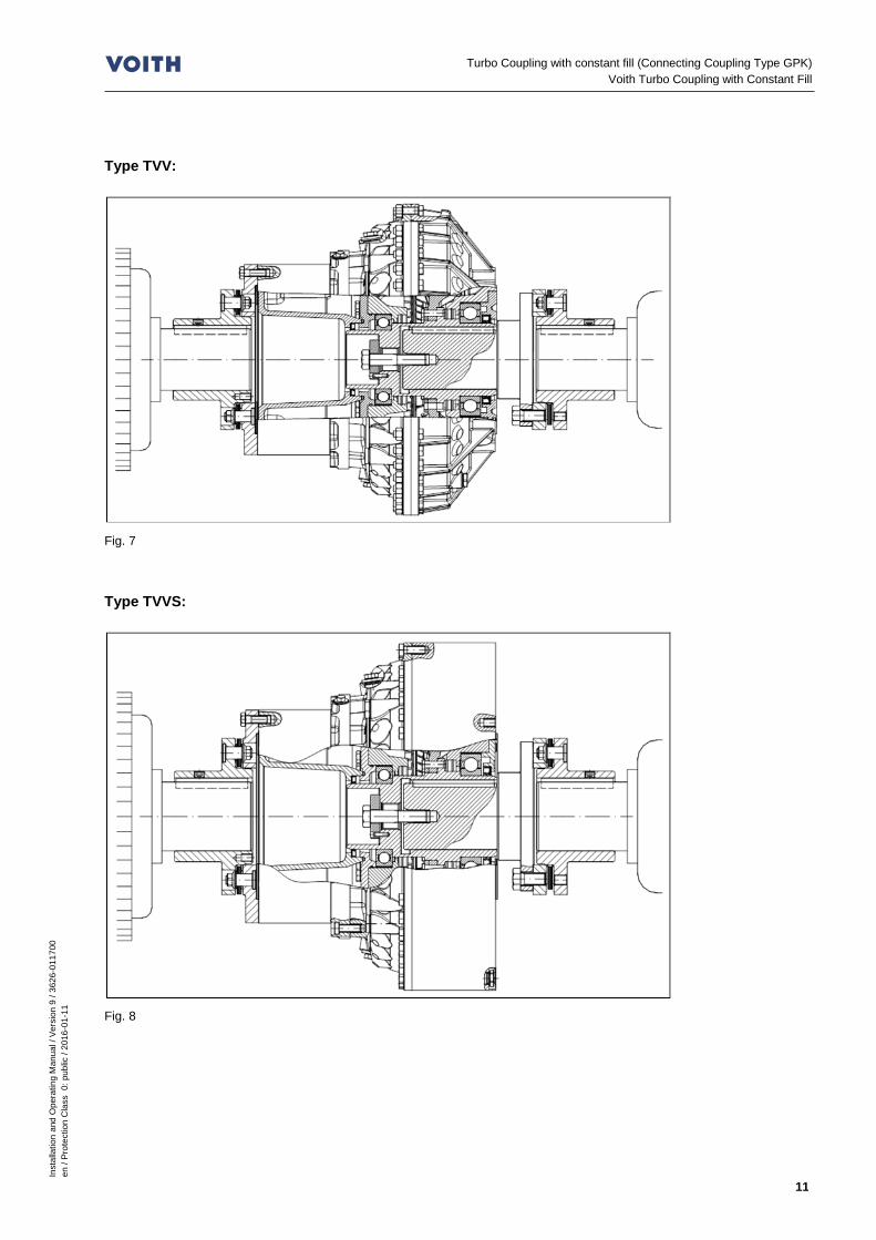
Type TVV:
Fig. 7 Type TVVS:
Fig. 8

Inst
alla
tion
and
Ope
ratin
g M
anua
l / V
ersi
on 9
/ 36
26-0
1170
0 en
/ Pr
otec
tion
Cla
ss 0
: pub
lic /
2016
-01-
11
12
Turbo Coupling with constant fill (Connecting Coupling Type GPK) Voith Turbo Coupling with Constant Fill
Type DT:
Fig. 9 Type DTV:
Fig. 10
Inst
alla
tion
and
Ope
ratin
g M
anua
l / V
ersi
on 9
/ 36
26-0
1170
0 en
/ Pr
otec
tion
Cla
ss 0
: pub
lic /
2016
-01-
11
13
Turbo Coupling with constant fill (Connecting Coupling Type GPK) Voith Turbo Coupling with Constant Fill
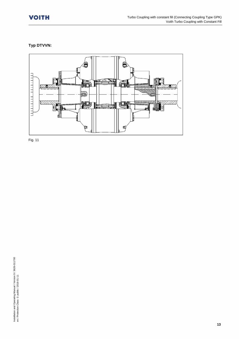
Typ DTVVN:
Fig. 11

Inst
alla
tion
and
Ope
ratin
g M
anua
l / V
ersi
on 9
/ 36
26-0
1170
0 en
/ Pr
otec
tion
Cla
ss 0
: pub
lic /
2016
-01-
11
14
Turbo Coupling with constant fill (Connecting Coupling Type GPK) Technical data
2 Technical data Information required for use in potentially explosive atmospheres:
marking:
Ambient temperature, if deviating from -25 °C Ta 40 °C °C
max. surface temperature (T3= 200 °C, T4= 135 °C, or deviating)
°C
Temperature monitoring MTS 1) for pre-warning
BTS 2) for pre-warning
BTS-Ex 2) for limitation of the max. surface temperature for Voith turbo couplings acc. to ATEX Directive.
Maximum permissible temperature of turbo coupling when switching on the motor:
°C
Nominal response temperature of temperature monitoring
°C
Max. permissible filling volume 3) dm3 (liters)
Overload (à Chapter 6.8), causing the thermal fuse (fusible plug/s and/or BTS-Ex) to respond, requires the power supply to be switched off after
s (sec)
An additional monitoring of the output speed is required to switch off the power supply before the fusible plugs respond.
Yes
No
After switching on the motor, monitoring of output speed has to begin after
s (sec)
Diameter of input 4) mm
Diameter of output 4) mm Replacement of ball and roller bearings after h
Table 1
1) MTS: Mechanical thermal switch unit ( Chapter 19.1). 2) BTS: Non-contacting thermal switch unit ( Chapter 19.2). 3) Applies if filling volume is not indicated on the cover sheet. 4) Diameter and fit of hub or shaft to be joined by means of shaft-hub connection.

Inst
alla
tion
and
Ope
ratin
g M
anua
l / V
ersi
on 9
/ 36
26-0
1170
0 en
/ Pr
otec
tion
Cla
ss 0
: pub
lic /
2016
-01-
11
15
Turbo Coupling with constant fill (Connecting Coupling Type GPK) Technical data
Additional information/data required for use in potentially explosive atmospheres:
Inst
alla
tion
and
Ope
ratin
g M
anua
l / V
ersi
on 9
/ 36
26-0
1170
0 en
/ Pr
otec
tion
Cla
ss 0
: pub
lic /
2016
-01-
11
16
Turbo Coupling with constant fill (Connecting Coupling Type GPK) Tightening torques
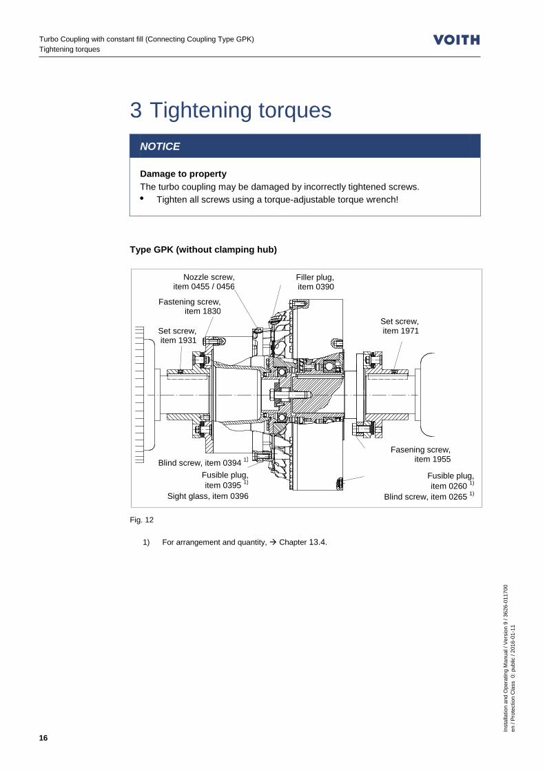
3 Tightening torques NOTICE
Damage to property The turbo coupling may be damaged by incorrectly tightened screws. • Tighten all screws using a torque-adjustable torque wrench!
Type GPK (without clamping hub)
Fig. 12
1) For arrangement and quantity, Chapter 13.4.
Set screw, item 1931
Blind screw, item 0394 1)
Fusible plug, item 0395 1)
Sight glass, item 0396
Fastening screw, item 1830
Fusible plug, item 0260 1)
Blind screw, item 0265 1)
Set screw, item 1971
Fasening screw, item 1955
Filler plug, item 0390
Nozzle screw, item 0455 / 0456
Inst
alla
tion
and
Ope
ratin
g M
anua
l / V
ersi
on 9
/ 36
26-0
1170
0 en
/ Pr
otec
tion
Cla
ss 0
: pub
lic /
2016
-01-
11
17
Turbo Coupling with constant fill (Connecting Coupling Type GPK) Tightening torques
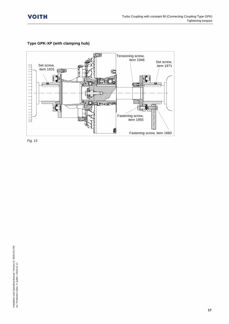
Type GPK-XP (with clamping hub)
Fig. 13
Fastening screw, item 1660
Fastening screw, item 1955
Set screw, item 1971
Tensioning screw, item 1946
Set screw, item 1931
Inst
alla
tion
and
Ope
ratin
g M
anua
l / V
ersi
on 9
/ 36
26-0
1170
0 en
/ P
rote
ctio
n C
lass
0: p
ublic
/ 20
16-0
1-11
18
Turbo Coupling with constant fill (Connecting Coupling Type GPK) Tightening torques
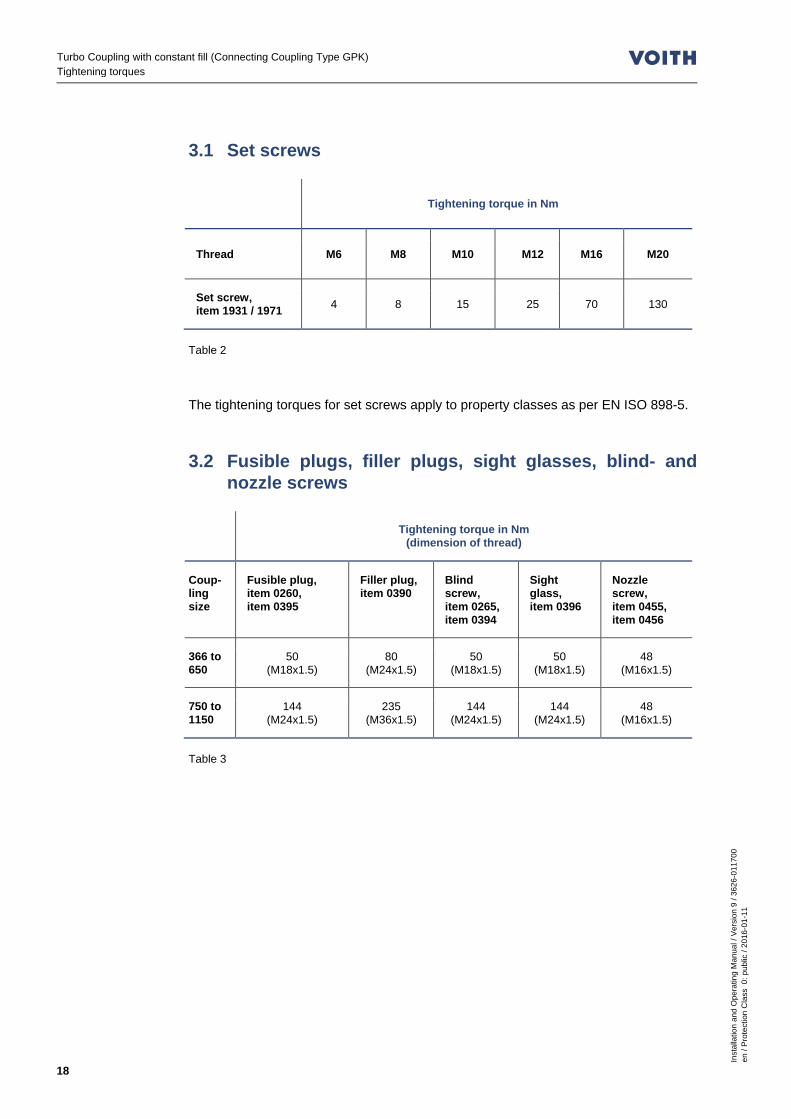
3.1 Set screws
Tightening torque in Nm
Thread M6 M8 M10 M12 M16 M20
Set screw, item 1931 / 1971 4 8 15 25 70 130
Table 2 The tightening torques for set screws apply to property classes as per EN ISO 898-5. 3.2 Fusible plugs, filler plugs, sight glasses, blind- and
nozzle screws
Tightening torque in Nm (dimension of thread)
Coup-ling size
Fusible plug, item 0260, item 0395
Filler plug, item 0390
Blind screw, item 0265, item 0394
Sight glass, item 0396
Nozzle screw, item 0455, item 0456
366 to 650
50 (M18x1.5)
80 (M24x1.5)
50 (M18x1.5)
50 (M18x1.5)
48 (M16x1.5)
750 to 1150
144 (M24x1.5)
235 (M36x1.5)
144 (M24x1.5)
144 (M24x1.5)
48 (M16x1.5)
Table 3

Inst
alla
tion
and
Ope
ratin
g M
anua
l / V
ersi
on 9
/ 36
26-0
1170
0 en
/ Pr
otec
tion
Cla
ss 0
: pub
lic /
2016
-01-
11
19
Turbo Coupling with constant fill (Connecting Coupling Type GPK) Tightening torques
3.3 Fastening screws
Tightening torque in Nm (dimension of thread)
Coupling size and type
Fastening screw, Item 1660
Fastening screw, Item 1830
Fastening screw, Item 1955
Tensioning screw, Item 1946
366 T 80 (M12)
68 (M12)
139 (M14)
26 (M8)
422 T 195 (M16)
68 (M12)
210 (M16)
26 (M8)
487 T 195 (M16)
68 (M12)
410 (M20)
52 (M10)
562 T 195 (M16)
68 (M12)
580 (M22)
52 (M10)
650 T 195 (M16)
135 (M16)
410 (M20)
90 (M12)
750 T 380 (M20)
135 (M16)
580 (M22)
90 (M12)
866 T 710 (M24)
250 (M20)
710 (M24)
216 (M16)
866 DT 380 (M20)
250 (M20)
615 1)
(M20) 424
(M20)
1000 T 380 (M20)
250 (M20)
615 1)
(M20) 424
(M20)
1000 DT -
250 (M20)
615 1)
(M20) 730
(M24)
1150 T -
580 (M27)
615 1)
(M20) 730
(M24)
1150 DT -
580 (M27)
1060 1)
(M24) 730
(M24)
Table 4 Screws with property class 8.8 or higher as per EN ISO 898-1 are used.
1) Screws with property class 10.9 as per EN ISO 898-1 are required.

Inst
alla
tion
and
Ope
ratin
g M
anua
l / V
ersi
on 9
/ 36
26-0
1170
0 en
/ Pr
otec
tion
Cla
ss 0
: pub
lic /
2016
-01-
11
20
Turbo Coupling with constant fill (Connecting Coupling Type GPK) Declarations of Manufacturer
4 Declarations of Manufacturer 4.1 Declaration regarding assemblies and components Since 29 December 2009, a new Machinery Directive 2006/42/EC has to be applied bindingly in the member states of the European Community. Voith turbo couplings of Product Group "Start-up Components", as defined by the new Machinery Directive 2006/42/EC and the explanations of the guidelines published in December 2009 to implement the Machinery Directive, are neither "machines" nor "incomplete machinery", but rather assemblies or components. As our products are no incomplete machinery, we do not issue a declaration of incor-poration as per Machinery Directive 2006/42/EC. An EC Declaration of Conformity must not be issued for these products either, nor CE marking be provided, unless specified by other EC directives or regulations. Voith as certified company ensures that the basic safety and health requirements for their products are always met by internal quality management systems and by applying harmonized standards. The technical documentation for Voith products is so comprehensive that they may be installed reliably into machinery or incomplete machinery. Safe operation of the complete machinery with regard to Voith products is also ensured at a later date when observing this documentation. Issued in Crailsheim, Germany On January 10, 2014 Name of Mr. J. Hagedorn, the undersigned General Manager - Start-up Components

Inst
alla
tion
and
Ope
ratin
g M
anua
l / V
ersi
on 9
/ 36
26-0
1170
0 en
/ Pr
otec
tion
Cla
ss 0
: pub
lic /
2016
-01-
11
21
Turbo Coupling with constant fill (Connecting Coupling Type GPK) Declarations of Manufacturer
4.2 Conformity Declaration EC Conformity Declaration as per Directive 94/9/EC (valid until April 19, 2016), EU Conformity Declaration as per Directive 2014/34/EU (valid from April 20, 2016) The manufacturer Voith Turbo GmbH & Co. KG,
Voithstraße 1, 74564 Crailsheim / Germany hereby declares that the machinery described below: Designation T… (with GPK)
Turbo coupling with constant fill, Connecting Coupling type GPK (all-metal disk pack coupling)
Serial number see shipping documents complies with the provisions of the following harmonized standards in the version valid on the date of signature: EN ISO 12100-1 / -2 Safety of machinery - basic concepts and general principles for
design Part 1: Terminology, methodology Part 2: Technical principles
EN 1127-1 / -2 Explosive atmospheres, explosion prevention, basic concepts and methodology
EN 13463-1 Non-electrical equipment for use in potentially explosive atmospheres, Part 1: Basic method and requirements
EN 13463-5 Non-electrical equipment intended for use in potentially explosive atmospheres, Part 5: Protection by constructional safety 'c'
EN 13463-8 Non-electrical equipment for potentially explosive atmospheres, Part 8: Protection by liquid immersion „k“
EN 1710 Equipment and components intended for use in potentially explosive atmospheres in underground mines
as well as with the following European and national standards and technical specifications in the version valid on the date of signature: TRBS 2153 Avoidance of ignition hazards resulting from electrostatic
charging Each modification by the customer on the parts supplied, invalidates the declaration. Issued in Crailsheim, Germany On November 25, 2015 Name of Mr. J. Hagedorn, the undersigned General Manager - Start-up Components

Inst
alla
tion
and
Ope
ratin
g M
anua
l / V
ersi
on 9
/ 36
26-0
1170
0 en
/ Pr
otec
tion
Cla
ss 0
: pub
lic /
2016
-01-
11
22
Turbo Coupling with constant fill (Connecting Coupling Type GPK) User information
5 User information This manual will support you in using the turbo coupling with connection coupling type GPK in a safe, proper and economical way. If you observe the information contained in this manual, you will – increase the reliability and lifetime of the turbo coupling and installation, – avoid any risks – reduce repairs and downtimes This manual must – always to be available at the machine jobsite – be read and used by every person who transports the turbo coupling, works on
the turbo coupling or commissions the same. The turbo coupling has been manufactured according to the latest design standard and approved safety regulations. Nevertheless, the user's or third party's life may be endangered or the machine or other property impaired in case of improper handling or unintended use. Spare parts: Spare parts must comply with the requirements determined by Voith. This is guaranteed when original spare parts are used. Installation and/or use of non-original spare parts may negatively change the mechanical properties of the Voith turbo coupling and thus have an adverse impact on safety. Voith is not liable for any damages resulting from the use of non-original spare parts. Use only appropriate workshop equipment for maintenance. Professional maintenance and/or repair can only be guaranteed by the manufacturer or an authorized specialist workshop.
Inst
alla
tion
and
Ope
ratin
g M
anua
l / V
ersi
on 9
/ 36
26-0
1170
0 en
/ Pr
otec
tion
Cla
ss 0
: pub
lic /
2016
-01-
11
23
Turbo Coupling with constant fill (Connecting Coupling Type GPK) User information
This manual has been issued with the utmost care. However, should you need any further information, please contact: Voith Turbo GmbH & Co. KG Division Mining & Metals Voithstr. 1 74564 Crailsheim, GERMANY Tel. +49 7951 32 409 Fax +49 7951 32 480 [email protected] www.voith.com/fluid-couplings © Voith Turbo 2016. The distribution as well as the reproduction of this document and the utilization and communication of its contents are prohibited unless expressly permitted. Offenders will be held liable for the payment of damages. All rights reserved in case a patent is granted, or a utility model or design is registered. Voith Turbo reserves the right for modifications.

Inst
alla
tion
and
Ope
ratin
g M
anua
l / V
ersi
on 9
/ 36
26-0
1170
0 en
/ Pr
otec
tion
Cla
ss 0
: pub
lic /
2016
-01-
11
24
Turbo Coupling with constant fill (Connecting Coupling Type GPK) Safety
6 Safety 6.1 Safety information Safety information indicating the descriptions and symbols as described in the following are used in the operating manual. 6.1.1 Structure of safety information
DANGER WORD
Hazard consequences Source of hazard • Warding off of danger
Danger word The danger word divides the severity of the danger in several levels:
Danger word Severity of danger
DANGER Death or serious injury (irreversible personal injury)
WARNING Death or serious injury possible
CAUTION Minor or moderate injury possible
NOTICE Possibly damage to property of - the product - its environment
SAFETY INFORMATION General applications details, useful information, safe job procedure and proper safety measures
Table 5 Hazard consequences Hazard consequences indicate the kind of hazard. Source of hazard The source of hazard indicates the cause of hazard. Warding off of danger Warding off of danger describes the measures to be taken to ward off a danger

Inst
alla
tion
and
Ope
ratin
g M
anua
l / V
ersi
on 9
/ 36
26-0
1170
0 en
/ Pr
otec
tion
Cla
ss 0
: pub
lic /
2016
-01-
11
25
Turbo Coupling with constant fill (Connecting Coupling Type GPK) Safety
6.1.2 Definition of safety symbols
Symbol Definition
Danger of explosion Marking with the Ex-symbol indicates possible hazards which have to be observed for the use in potentially explosive atmospheres.
Table 6 6.2 Intended use The turbo coupling with constant fill (type of connecting coupling GPK) is provided to transmit the torque from the drive motor to the driven machine in case of horizontal installation (max. 7°). The power permitted during stationary operation at a specific input speed and a specific coupling filling (operating fluid and filling) is entered on the cover sheet of this manual. Any use beyond that is deemed unintended ( Chapter 6.3 Unintended use). Intended use also includes observing this installation and operating manual and complying with the inspection and maintenance conditions. The manufacturer is not liable for any damages resulting from unintended use. The risk has to be borne solely by the user.
SAFETY INFORMATION
• If not indicated accordingly in Chapter 2, it is not allowed to use this turbo coupling in potentially explosive atmospheres!
• Please check with reference to the marking whether the turbo coupling is approved for potentially explosive atmospheres.
• If the zonal classification changes, the operator has to check whether it is still allowed to operate the turbo coupling in that zone.
A marking according to ATEX Directive and EN13463 has been provided on the periphery of the turbo couplings. The marking specifies in what potentially explosive atmospheres and under what conditions the use is permitted. Example: II 2D c 180 C X Industrial area in which during normal operation an explosive atmosphere may form ocassionally in form of a cloud of combustible dust in the air. Mechanical explosion protection by constructional safety. Maximum surface temperature: 180 °C.

Inst
alla
tion
and
Ope
ratin
g M
anua
l / V
ersi
on 9
/ 36
26-0
1170
0 en
/ Pr
otec
tion
Cla
ss 0
: pub
lic /
2016
-01-
11
26
Turbo Coupling with constant fill (Connecting Coupling Type GPK) Safety
6.3 Unintended use The power transmission permitted during stationary operation at a specific input speed and a specific coupling filling (operating fluid and quantity) is entered on the cover sheet of this manual. Any use beyond that described herein, e.g. for higher powers, higher speeds, other operating fluids or operating conditions that have not been agreed upon, is considered unintended use. Moreover, it is not permitted to use BTS-Ex non-contacting thermal switch units from third parties.
6.4 Structural modifications
WARNING
Risk of personal injuries and damage to property Structural modifications not done properly on the turbo coupling may cause personal injury and damage to property. • Modifications, attachments or conversions on the turbo coupling are only
allowed with the approval of Voith Turbo GmbH & Co. KG, Crailsheim.
6.5 General information as to dangerous situations For all work performed on the turbo coupling, please observe the local regulations for the prevention of accidents! Hazards while working on the turbo coupling:
WARNING
Risk of injury While working on the turbo coupling, there is the risk of injury through cutting, crushing, burns and cold burns in case of minus degrees. • Never touch the turbo coupling without wearing protective golves. • Start to work on the turbo coupling only after it has cooled down to below
44 °C! • Ensure that there is sufficient light, a sufficiently large working space and
good ventilation when working on the turbo coupling. • Switch off the unit in which the turbo coupling is installed and secure the
switch against inadvertent switch-on. • For all work performed on the turbo coupling ensure that both the drive motor
and the driven machine have stopped running and that a re-start is absolutely impossible!
Inst
alla
tion
and
Ope
ratin
g M
anua
l / V
ersi
on 9
/ 36
26-0
1170
0 en
/ Pr
otec
tion
Cla
ss 0
: pub
lic /
2016
-01-
11
27
Turbo Coupling with constant fill (Connecting Coupling Type GPK) Safety
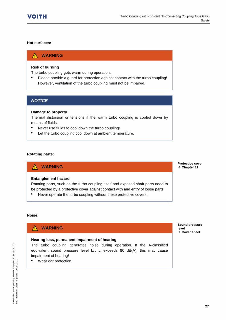
Hot surfaces:
WARNING
Risk of burning The turbo coupling gets warm during operation. • Please provide a guard for protection against contact with the turbo coupling!
However, ventilation of the turbo coupling must not be impaired.
NOTICE
Damage to property Thermal distorsion or tensions if the warm turbo coupling is cooled down by means of fluids. • Never use fluids to cool down the turbo coupling! • Let the turbo coupling cool down at ambient temperature.
Rotating parts:
WARNING
Entanglement hazard Rotating parts, such as the turbo coupling itself and exposed shaft parts need to be protected by a protective cover against contact with and entry of loose parts. • Never operate the turbo coupling without these protective covers.
Noise:
WARNING
Hearing loss, permanent impairment of hearing The turbo coupling generates noise during operation. If the A-classified equivalent sound pressure level LPA, 1m exceeds 80 dB(A), this may cause impairment of hearing! • Wear ear protection.
Protective cover Chapter 11
Sound pressure level Cover sheet

Inst
alla
tion
and
Ope
ratin
g M
anua
l / V
ersi
on 9
/ 36
26-0
1170
0 en
/ Pr
otec
tion
Cla
ss 0
: pub
lic /
2016
-01-
11
28
Turbo Coupling with constant fill (Connecting Coupling Type GPK) Safety
Electric shock:
DANGER
Electric shock On account of incorrectly mounted or incorrectly connected electrical components, and disconnected electric connections, persons could get an electric shock and be severely injured, possibly with fatal consequences. Incorrectly mounted or incorrectly connected electrical components and disconnected electric connections may cause damages to the machine. • A qualified electrician has to properly carry out the connection to the electric
supply network considering the system voltage and the maximum power con-sumption!
• The system voltage has to be in conformity with the system voltage indicated on the nameplate!
• There has to be a corresponding electrical protection by a fuse on the network side!
DANGER
Electrostatic processes Electrostatic charging may injure persons by an electric shock. • Allow only a qualified electrician to install the equipment into which the turbo
coupling is installed. • Machine and electric installation are provided with grounding connections.
Overspeed:
NOTICE
Damage to property Non-recognition of overspeed, wrong direction of rotation or parameters outside the tolerance due to incorrect programming, may destroy the turbo coupling. • Check wheter the entire system is equipped with a device which safely
prevents overspeed (for example brake or backstop). • For rated speed, cover sheet..
This refers only to installations where overspeed (exceeding the rated speed) is possible.
Inst
alla
tion
and
Ope
ratin
g M
anua
l / V
ersi
on 9
/ 36
26-0
1170
0 en
/ Pr
otec
tion
Cla
ss 0
: pub
lic /
2016
-01-
11
29
Turbo Coupling with constant fill (Connecting Coupling Type GPK) Safety
Extreme ambient temperatures:
WARNING
Risk of personal injuries and damage to property Extreme ambient temperatures may result in thermal overload of the turbo coupling, thus causing the fusible plugs to melt and seriously injure any persons in their immediate surroundings, and to cause damage to the turbo coupling. • Observe the permissible ambient temperature.
NOTICE
Damage to property The turbo coupling may be damaged by frozen operating fluid. • The ambient temperature must be above the freezing point of the operating
fluid. • Adhere to the temperature limits indicated ( Chapter 6.8).
Operating fluid which sprays off or leaks out:
WARNING
Risk of losing sight due to operating fluid spraying off, risk of burning In case of thermal overload of the turbo coupling, the fusible plugs respond. Operating fluid leaks out through these fusible plugs. • Persons close to the turbo coupling must wear safety goggles. • Please make sure that the spraying-off operating fluid cannot get in contact
with persons. • If the fusible plugs spray off, switch off the drive immediately. • Electrical devices located near the coupling need to be splash-guarded.
Ambient temperature Chapter 2
Only when water is used as operating fluid

Inst
alla
tion
and
Ope
ratin
g M
anua
l / V
ersi
on 9
/ 36
26-0
1170
0 en
/ Pr
otec
tion
Cla
ss 0
: pub
lic /
2016
-01-
11
30
Turbo Coupling with constant fill (Connecting Coupling Type GPK) Safety
WARNING
Fire hazard After the fusible plugs responded, spraying off oil may ignite on hot surfaces causing fire, as well as releasing toxic gases and vapor. • Make sure that spraying off operating fluid cannot get into contact with hot
machine parts, heaters, sparks or open flames. • Immediately switch off the driving machine when the fusible plugs respond. • Please pay attention to the information contained in the safety data sheets.
CAUTION
Danger of slipping Slipping hazard due to spraying off solder of fusible plugs and leaking out operating fluid. • Please provide a catch pan of sufficient size. • Immediately remove any leaking out solder and operating fluid. • Please pay attention to the information contained in the safety data sheets.
Checking the methane content before working on the turbo coupling:
WARNING
Explosion hazard For turbo couplings with housings made of aluminum alloys and when the protective cover was removed, if the permissible methane content is exceeded, there is the risk of explosion. • Before and during all work performed on the turbo coupling, check the
methane content around the turbo coupling. • Should this permissible limit value be exceeded, the work has to be stopped
until the value is again below the limit value.
Permissible limit values according to local regulations

Inst
alla
tion
and
Ope
ratin
g M
anua
l / V
ersi
on 9
/ 36
26-0
1170
0 en
/ Pr
otec
tion
Cla
ss 0
: pub
lic /
2016
-01-
11
31
Turbo Coupling with constant fill (Connecting Coupling Type GPK) Safety
6.6 Remaining risks
WARNING
Risk of personal injuries and damage to property Unintended use or incorrect operation may cause death, serious injuries or minor injuries as well as damage to property and the environment. • Only persons who are sufficiently qualified, trained and authorized are
allowed to work on or with the turbo coupling. • Please observe the warnings and safety information.
6.7 What to do in case of accidents
SAFETY INFORMATION
• In case of accidents, please observe the local regulations, the operating manuals and the operator's safety measures.
6.8 Information with regard to operation
SAFETY INFORMATION
• If irregularities are found during operation, immediately switch off the drive unit.
Power transmission: The cover sheet of this manual indicates the possible power transmission at a specific input speed and a specific coupling filling (operating fluid and quantity). These values describe a permissible working point for the stationary operation of the turbo coupling.
NOTICE
Damage to property Deviations from the permissible working point cause damage the turbo coupling. • Voith Turbo's approval is required for a stationary operation of the turbo
coupling at a different working point.

Inst
alla
tion
and
Ope
ratin
g M
anua
l / V
ersi
on 9
/ 36
26-0
1170
0 en
/ Pr
otec
tion
Cla
ss 0
: pub
lic /
2016
-01-
11
32
Turbo Coupling with constant fill (Connecting Coupling Type GPK) Safety
Operating fluid:
NOTICE
Damage to property Too little filling results in thermal overload of the turbo coupling, and in case of too much filling, the turbo coupling may be damaged by internal pressure. • Operate the turbo coupling only with the filling quantity stated on the cover
sheet of this manual. • Use only the operating fluid indicated on the cover sheet of this manual.
Heating up during start-up:
NOTICE
Damage to property During start-up, the turbo coupling heats up more than during stationary operation due to the increased slip. • Please provide sufficient intervals between start-ups to avoid thermal
overload.
Starting characteristic of turbo couplings with delay chamber: On start-up, the operating fluid flows from the delay chamber into the turbo coupling working chamber. On standstill, the operating fluid returns into the delay chamber. Please provide sufficient intervals (a few minutes) between the starts to get a correct starting characteristic.

Inst
alla
tion
and
Ope
ratin
g M
anua
l / V
ersi
on 9
/ 36
26-0
1170
0 en
/ Pr
otec
tion
Cla
ss 0
: pub
lic /
2016
-01-
11
33
Turbo Coupling with constant fill (Connecting Coupling Type GPK) Safety
Coupling temperature:
NOTICE
Damage due to under temperature The turbo coupling may be damaged by under temperature. • Please consult Voith Turbo if the turbo coupling shall be used at ambient
temperatures • below -25 °C for operating fluid 'oil' • below 1 °C for operating fluid 'water'
NOTICE
Damage due to overheating Overheating (nominal temperature is exceeded) may damage the turbo coupling. • Provide sufficient ventilation / aeration of the turbo coupling.
Fusible plugs: The fusible plugs protect the turbo coupling against damage due to thermal overload.
NOTICE
Damage to property The turbo coupling will be damaged if operation is continued after a fusible plug responded. • Switch off the drive motor immediately on response of one of the fusible
plugs! • Use original fusible plugs only with the response temperature indicated on
the cover sheet of this operating manual.
WARNING
Explosion hazard Explosion hazard due to high temperature of turbo coupling. • Make sure that the air surrounding the turbo coupling does not exceed the
permissible value.
Technical data Chapter 2 and order documents
Technical data Chapter 2
Inst
alla
tion
and
Ope
ratin
g M
anua
l / V
ersi
on 9
/ 36
26-0
1170
0 en
/ Pr
otec
tion
Cla
ss 0
: pub
lic /
2016
-01-
11
34
Turbo Coupling with constant fill (Connecting Coupling Type GPK) Safety
Monitoring devices:
NOTICE
Damage to property Damage to turbo coupling due to monitoring devices not ready for service. • Check whether existing monitoring devices are in a state ready for service. • Repair any defective monitoring device immediately. • Never bypass safety devices.
Blocking:
NOTICE
Damage to property Blocking of the driven machine may cause overheating of the turbo coupling and response of the fusible plugs thus endangering persons as well as the turbo coupling and environment. • Immediately switch off the driving machine.
Overload of turbo coupling: After the thermal fuse responded, switch off the power supply after the time required in Chapter 2 at the latest. In case of multi-motor drive, switch off the whole system! If an additional monitoring of the overload is required, monitor the output speed. If the output speed falls below the input speed by more than 10%, immediately switch off the power supply. It is necessary to switch off the power supply as otherwise the permissible surface temperature indicated cannot be met.
NOTICE
Overload of turbo coupling The turbo coupling will be overloaded in cases where • the driven machine blocks • the driven machine is loaded excessively during nominal operation and/or
during start-up.
Please consult Voith Turbo in case of unforeseeable turbo coupling overload.
Monitoring devices Chapter 19
Permissible surface temperature, Chapter 2

Inst
alla
tion
and
Ope
ratin
g M
anua
l / V
ersi
on 9
/ 36
26-0
1170
0 en
/ Pr
otec
tion
Cla
ss 0
: pub
lic /
2016
-01-
11
35
Turbo Coupling with constant fill (Connecting Coupling Type GPK) Safety
6.9 Qualification of staff Only qualified and authorized professional staff are allowed to perform work, such as transportation, storage, installation, electrical connection, commissioning, operation, maintenance, servicing and repair. Qualified professional staff in the sense of this operating manual are persons who are familiar with transportation, storage, installation, electrical connection, commissioning, maintenance, servicing and repair and who have got the necessary qualifications relevant to their job performed. Qualification has to be ensured by performing training and giving instructions on the turbo coupling. This staff must be trained, instructed and authorized to: – operate and service machines in a professional manner in accordance with the
technical safety standards. – use lifting appliances, slings (ropes, chains, etc.) and lifting points in a
professional manner. – properly dispose of media and their components, e.g. lubricating grease. – service and use safety devices in a manner that ensures compliance with safety
standards. – prevent accidents and provide first aid. Staff to be trained may only perform work on the turbo coupling under the supervision of a qualified and authorized person. The staff in charge of any work to be done on the coupling must – be reliable, – have the legal age, – be trained, instructed and authorized with regard to the intended work. 6.10 Product monitoring We are under legal obligation to keep the performance of our products under observation, even after shipment. Therefore, please inform us about anything that might be of interest to us. For example: – Change in operating data, – experience gained with the machine, – recurring problems, – problems experienced with this installation and operating manual.
Our address, Page 2
Inst
alla
tion
and
Ope
ratin
g M
anua
l / V
ersi
on 9
/ 36
26-0
1170
0 en
/ Pr
otec
tion
Cla
ss 0
: pub
lic /
2016
-01-
11
36
Turbo Coupling with constant fill (Connecting Coupling Type GPK) Transport and Storage
7 Transport and Storage 7.1 As delivered condition – The turbo coupling is delivered in ready-mounted condition. – The turbo coupling is not filled. If the scope of supply includes the operating fluid,
it will be delivered in a separate container. Type GPK (without clamping hub): Type GPK (without clamping hub): The input and output hubs with disk packs will be supplied separately; the stub shaft is mounted. The hex. screws (item 1942) of the transport protector to pretension the disk packs are screwed in and are not tensioned. Spacer sleeves (item 1943) keep the disk packs at distance which are therefore not overstretched. Type GPK-XP (with clamping hub): The clamping hub, input and output hubs with disk packs, if necessary with brake disk / brake drum will be supplied separately; the plug-in shaft is mounted. The hex. screws (item 1942) of the transport protector are screwed in. Spacer sleeves (item 1943) keep the disk packs at distance which are therefore not overstretched. 7.2 Scope of supply The turbo coupling will be supplied as indicated on the cover sheet. A set of fusible plugs is supplied as spare one. Additional parts belonging to the scope of supply, such as connecting coupling, fusible plugs, temperature monitoring, mounting and removal device, etc. will be stated in the order confirmation.
Packaging Chapter 7.5

Inst
alla
tion
and
Ope
ratin
g M
anua
l / V
ersi
on 9
/ 36
26-0
1170
0 en
/ Pr
otec
tion
Cla
ss 0
: pub
lic /
2016
-01-
11
37
Turbo Coupling with constant fill (Connecting Coupling Type GPK) Transport and Storage
7.3 Transport
WARNING
Explosion hazard For turbo couplings with housings made of aluminum alloys, there can be the risk of explosion when being transported in / through explosive atmospheres. • In potentially explosive atmospheres it is only allowed to transport the turbo
coupling in suitable packing. • This transport packing has to meet the same minimum requirements as the
protective cover.
WARNING
Risk of injury Falling parts may seriously injure or kill you. • Secure the turbo coupling sufficiently. • Pay attention to the center of gravity position. • Use the provided lifting points. • Use appropriate transportation means and slings (ropes, chains, etc.).
WARNING
Risk of crushing Incorrect handling of the turbo coupling may cause bruising of upper and lower limbs and seriously injure persons. • Skilled staff only is allowed to carry out transportation!
NOTICE
Damage to property The turbo coupling is installed with a „flexible“ suspension. In mounted condition, a transport of the turbo coupling is permitted in horizontal position only. The turbo coupling may be damaged due to inclinations. • In case of an inclination greater than 7°, it is necessary to secure the turbo
coupling axially.
Protective cover Chapter 11

Inst
alla
tion
and
Ope
ratin
g M
anua
l / V
ersi
on 9
/ 36
26-0
1170
0 en
/ Pr
otec
tion
Cla
ss 0
: pub
lic /
2016
-01-
11
38
Turbo Coupling with constant fill (Connecting Coupling Type GPK) Transport and Storage
7.4 Lifting Lifting appliances, load carrying attachments, lifting points Observe the turbo coupling weight! Lifting appliances (e.g. crane, high-lift truck), slings (ropes, chains, etc.) and lifting points (swivels, thread size as for item 1830, Chapter 3.3) need to be – checked and approved – sufficiently dimensioned and in sound condition, – and may only be operated by authorized and trained persons. It is not allowed to use eyebolts! Read the operating instructions for lifting appliances, slings (ropes, chains, etc.) and lifting points!
WARNING
Risk of injury Damaged load carrying attachments or those with insufficient carrying capacity may break under load, with the consequence of serious or even fatal injuries! • Check the lifting appliances and load carrying attachments for
- sufficient carrying capacity (for weight, cover sheet). - sound condition.
Fixing the turbo coupling
WARNING
Risk of injury Falling parts may seriously injure or kill you. • Do not walk under suspended loads.
For weight of the Turbo coupling Cover sheet Weights of over 100 kg will be stamped on the turbo coupling.

Inst
alla
tion
and
Ope
ratin
g M
anua
l / V
ersi
on 9
/ 36
26-0
1170
0 en
/ Pr
otec
tion
Cla
ss 0
: pub
lic /
2016
-01-
11
39
Turbo Coupling with constant fill (Connecting Coupling Type GPK) Transport and Storage
NOTICE
Personal injury and damage to property Improper fixing and lifting of the turbo coupling may cause personal injury and damage to property • It is only allowed to lift the turbo coupling at the lifting points provided for this
purpose (see the following pictures). • When fastening and lifting the turbo coupling, do not damage the ribbing of
the turbo coupling through lifting appliances or load carrying attachments. • Damaged ribs may result in unbalance of the turbo coupling, thus causing
uneven running of the machine.
• Screw suitable swivels (thread size as for item 1830, Chapter 3.3) into the
turbo coupling. Do not unscrew existing screws for this purpose; please use the threads provided.
• Fix the slings (ropes, chains, etc.).
Fig. 14

Inst
alla
tion
and
Ope
ratin
g M
anua
l / V
ersi
on 9
/ 36
26-0
1170
0 en
/ Pr
otec
tion
Cla
ss 0
: pub
lic /
2016
-01-
11
40
Turbo Coupling with constant fill (Connecting Coupling Type GPK) Transport and Storage
WARNING
Risk of injury Danger to life and risk of injury caused by falling load, tilting or sliding of the turbo coupling. • Slings (ropes, chains, etc.) must not be slung around the turbo coupling for
lifting. • Always use at least 2 slings (ropes, chains, etc.) for fixing. • Do not walk under suspended loads. • Observe the general guidelines for the prevention of accidents. • Secure the turbo coupling against tilting and sliding as long as it is not
mounted between the driving and driven machine.
Turning the turbo coupling • Screw suitable swivels (thread size as for item 1830, Chapter 3.3) into the
turbo coupling. Do not unscrew existing screws for this purpose; please use the threads provided.
• Fix the slings (ropes, chains, etc.).
Fig. 15

Inst
alla
tion
and
Ope
ratin
g M
anua
l / V
ersi
on 9
/ 36
26-0
1170
0 en
/ Pr
otec
tion
Cla
ss 0
: pub
lic /
2016
-01-
11
41
Turbo Coupling with constant fill (Connecting Coupling Type GPK) Transport and Storage
WARNING
Risk of crushing Incorrect handling of the turbo coupling may cause bruising of upper and lower limbs and seriously injure persons. • Always use at least 2 slings (ropes, chains, etc.) for fixing. • For turning, please use 2 slings (ropes, chains, etc.) on each side.
• On the opposite side, screw suitable swivels (thread size as for item 1830,
Chapter 3.3) into the turbo coupling. Do not unscrew existing screws for this purpose; please use the threads provided.
• Fix the turbo coupling to the second slings.
Fig. 16
Inst
alla
tion
and
Ope
ratin
g M
anua
l / V
ersi
on 9
/ 36
26-0
1170
0 en
/ Pr
otec
tion
Cla
ss 0
: pub
lic /
2016
-01-
11
42
Turbo Coupling with constant fill (Connecting Coupling Type GPK) Transport and Storage
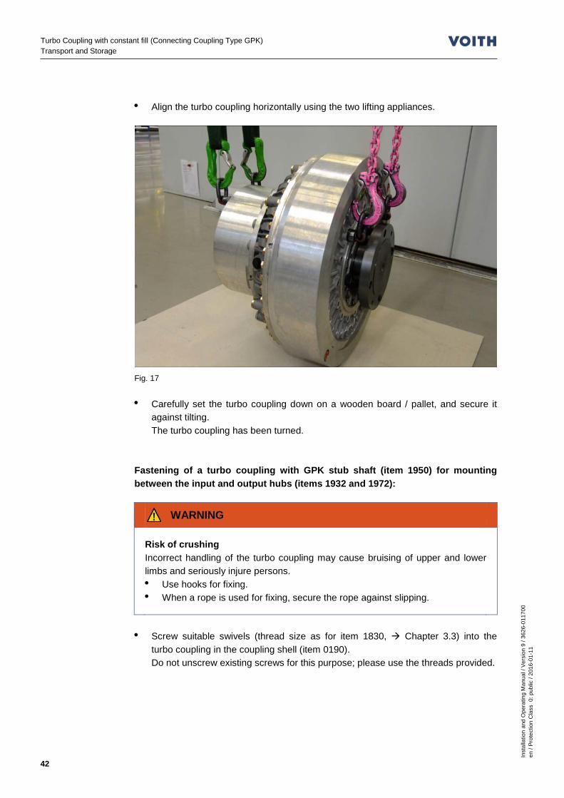
• Align the turbo coupling horizontally using the two lifting appliances.
Fig. 17 • Carefully set the turbo coupling down on a wooden board / pallet, and secure it
against tilting. The turbo coupling has been turned.
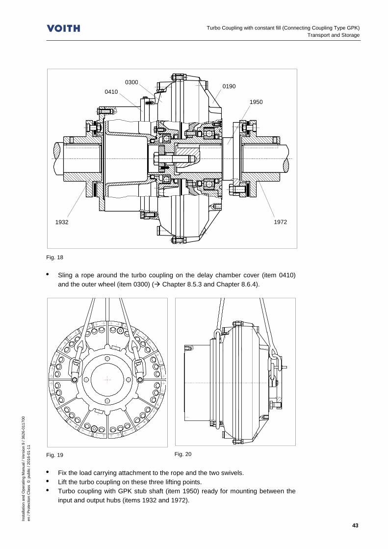
Fastening of a turbo coupling with GPK stub shaft (item 1950) for mounting between the input and output hubs (items 1932 and 1972):
WARNING
Risk of crushing Incorrect handling of the turbo coupling may cause bruising of upper and lower limbs and seriously injure persons. • Use hooks for fixing. • When a rope is used for fixing, secure the rope against slipping.
• Screw suitable swivels (thread size as for item 1830, Chapter 3.3) into the
turbo coupling in the coupling shell (item 0190). Do not unscrew existing screws for this purpose; please use the threads provided.
Inst
alla
tion
and
Ope
ratin
g M
anua
l / V
ersi
on 9
/ 36
26-0
1170
0 en
/ Pr
otec
tion
Cla
ss 0
: pub
lic /
2016
-01-
11
43
Turbo Coupling with constant fill (Connecting Coupling Type GPK) Transport and Storage
Fig. 18 • Sling a rope around the turbo coupling on the delay chamber cover (item 0410)
and the outer wheel (item 0300) ( Chapter 8.5.3 and Chapter 8.6.4).
Fig. 19
Fig. 20
• Fix the load carrying attachment to the rope and the two swivels. • Lift the turbo coupling on these three lifting points. • Turbo coupling with GPK stub shaft (item 1950) ready for mounting between the
input and output hubs (items 1932 and 1972).
0300 0410
1932 1972
1950
0190

Inst
alla
tion
and
Ope
ratin
g M
anua
l / V
ersi
on 9
/ 36
26-0
1170
0 en
/ Pr
otec
tion
Cla
ss 0
: pub
lic /
2016
-01-
11
44
Turbo Coupling with constant fill (Connecting Coupling Type GPK) Transport and Storage
7.5 Storage / Packing / Preservation As delivered condition The as delivered condition of the Voith Turbo Couplings depends on the mode of transport and the storage period: Condition No. 1 represents the delivered standard, for deviations, ordering documents.
Condition No.
- Transport - Admissible storage period
Packing / Measures taken
1 - Overland / air transport - Storage up to 6 months indoors (building)
- Device to suit transportation - Weather protection provided by the means of transport - Packed in PE foil
2 - Sea transport - Storage up to 6 months indoors (building)
- Device to suit transportation - Sharp edges protected - Shrink-wrapped in PE foil - Desiccant according to DIN 55473 / 55474 - Water-proof cardboard or wooden box/crate - Line the inside of the crate lid with sealed ribbed
PE sheets (Akylux). Put PVC foil underneath at butt joints
3 - Sea transport - Storage up to 12 months indoors (building)
- As for Condition No. 2 - Improved preservation
4 - Sea transport - Storage up to 24 months indoors (building)
- As for Condition No. 2 - Shrink-wrapped in aluminum sandwich foil instead of PE foil
Table 7 Opening of the packaging Foils that have been opened for inspection upon receipt are to be re-closed airtight for further storage. Use a new desiccant, if necessary. Disposal of the packaging Dispose of packaging material according to the local regulations. Extension of storage period The allowable storage period may be extended maximal three times according to the following descriptions. To do so, it is necessary to check the packaging and to possibly replace it. After replacing the desiccant, close the foil packings airtight. External preservation / re-preservation Renew the external preservation according to the allowable storage period. Spray bright metal parts (hub bores, brake disks, etc.) with Houghton Ensis DWG2462.
Notes on disposal Chapter 16

Inst
alla
tion
and
Ope
ratin
g M
anua
l / V
ersi
on 9
/ 36
26-0
1170
0 en
/ Pr
otec
tion
Cla
ss 0
: pub
lic /
2016
-01-
11
45
Turbo Coupling with constant fill (Connecting Coupling Type GPK) Transport and Storage
Internal preservation / re-preservation: Renew the internal preservation annually (for Condition No. 4: every 2 years). Wet the turbo coupling inside with an oil selected from the selection list. Selection list for internal preservation agents
Producer Designation
ARAL Aral Oil KONIT SAE 20W-20
Mobil Mobilarma 524 (SAE 30)
Houghton Ensis Engine Oil 20
Wintershall Wintershall Antikorrol 20W-20
The recommended operating fluids may also be used for preservation.
Table 8 Turbo coupling on bearings or mounted (turnable) For re-preservation, fill the turbo coupling with oil above the axis of rotation center and rotate the turbo coupling input and output at least once. Turbo coupling mounted (not turnable) Fill the turbo coupling up to the upper fusible plug. Then drain the oil and close the plug on the turbo coupling according to the specified procedure. The oil may remain in the turbo coupling for another scheduled re-preservation if it is ensured that prior to commissioning, the turbo coupling is filled with fresh oil (oil quantity according to design documents). Protect the turbo coupling against weather and environmental influences if it is installed in a machine that is not set into operation. Renew the external re-preservation every 6 months, internal re-preservation once a year. If necessary, clean the turbo coupling outside before performing re-preservation. Proceed for external and internal re-preservation as described above.
NOTICE
Damage to property Danger of frost • When storing turbo couplings of type "TW" below 1°C, drain the water.
Outside cleaning Chapter 13.1

Inst
alla
tion
and
Ope
ratin
g M
anua
l / V
ersi
on 9
/ 36
26-0
1170
0 en
/ Pr
otec
tion
Cla
ss 0
: pub
lic /
2016
-01-
11
46
Turbo Coupling with constant fill (Connecting Coupling Type GPK) Installation and alignment
8 Installation and alignment WARNING
Risk of injury Please observe, in particular, Chapter 6 (Safety) when working on the turbo coupling!
NOTICE
Damage to property Disk pack is damaged due to improper fixing of the turbo coupling. • If one or both hubs are removed, the weight of the turbo coupling needs to be
borne by suitable slings (ropes, chains, etc.).
8.1 Functioning of GPK (all-metal disk pack coupling) Type GPK (without clamping hub):
Fig. 21
Disk pack Disk pack
Input shaft
Input hub
Turbo coupling Stub shaft
Output hub
Output shaft

Inst
alla
tion
and
Ope
ratin
g M
anua
l / V
ersi
on 9
/ 36
26-0
1170
0 en
/ Pr
otec
tion
Cla
ss 0
: pub
lic /
2016
-01-
11
47
Turbo Coupling with constant fill (Connecting Coupling Type GPK) Installation and alignment
Type GPK-XP (with clamping hub):
Fig. 22 General – In case of horizontal installation, the turbo coupling weight is distributed on the
input and output shaft by means of two disk packs. – Permissible inclination of the turbo coupling without taking special measures is 7°
(consult Voith Turbo, if necessary). – The completely mounted disk packs form together with the hubs the GPK (all-
metal disk pack coupling). – The disk packs act torsionally stiff in circumferential direction, are flexible in
angular and axial direction. – Shaft displacements are compensated by this flexibility. 8.2 Tools
WARNING
Explosion hazard There is the risk of explosion when using unsuitable tools. • When using or assembling an Ex-coupling, use only tools approved for appli-
cation in potentially explosive atmospheres. • Observe the locally applicable regulations. • Avoid formation of sparks.
Brake disk (brake drum)
Plug-in shaft
Clamping hub
Inst
alla
tion
and
Ope
ratin
g M
anua
l / V
ersi
on 9
/ 36
26-0
1170
0 en
/ Pr
otec
tion
Cla
ss 0
: pub
lic /
2016
-01-
11
48
Turbo Coupling with constant fill (Connecting Coupling Type GPK) Installation and alignment
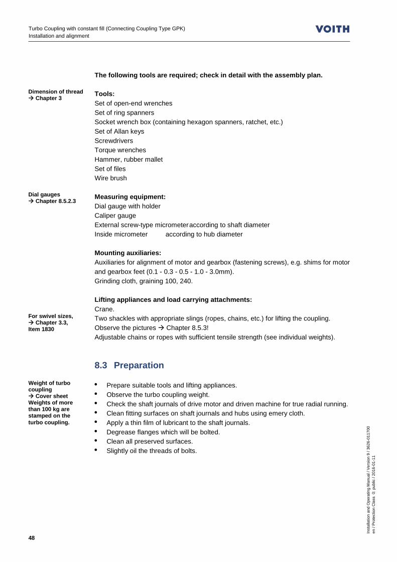
The following tools are required; check in detail with the assembly plan. Tools: Set of open-end wrenches Set of ring spanners Socket wrench box (containing hexagon spanners, ratchet, etc.) Set of Allan keys Screwdrivers Torque wrenches Hammer, rubber mallet Set of files Wire brush Measuring equipment: Dial gauge with holder Caliper gauge External screw-type micrometer according to shaft diameter Inside micrometer according to hub diameter Mounting auxiliaries: Auxiliaries for alignment of motor and gearbox (fastening screws), e.g. shims for motor and gearbox feet (0.1 - 0.3 - 0.5 - 1.0 - 3.0mm). Grinding cloth, graining 100, 240. Lifting appliances and load carrying attachments: Crane. Two shackles with appropriate slings (ropes, chains, etc.) for lifting the coupling. Observe the pictures Chapter 8.5.3! Adjustable chains or ropes with sufficient tensile strength (see individual weights). 8.3 Preparation • Prepare suitable tools and lifting appliances. • Observe the turbo coupling weight. • Check the shaft journals of drive motor and driven machine for true radial running. • Clean fitting surfaces on shaft journals and hubs using emery cloth. • Apply a thin film of lubricant to the shaft journals. • Degrease flanges which will be bolted. • Clean all preserved surfaces. • Slightly oil the threads of bolts.
Dimension of thread Chapter 3
Dial gauges Chapter 8.5.2.3
For swivel sizes, Chapter 3.3, Item 1830
Weight of turbo coupling Cover sheet Weights of more than 100 kg are stamped on the turbo coupling.

Inst
alla
tion
and
Ope
ratin
g M
anua
l / V
ersi
on 9
/ 36
26-0
1170
0 en
/ Pr
otec
tion
Cla
ss 0
: pub
lic /
2016
-01-
11
49
Turbo Coupling with constant fill (Connecting Coupling Type GPK) Installation and alignment
SAFETY INFORMATION
Use a lubricant with the following characteristics: • Operating temperature range: -20 °C…180 °C, • Water- and wash-out-resistant • Protection against fretting corrosion and corrosion
Proposed lubricants:
Producer Designation Note
Dow Corning Molykote G-N Plus Paste Molykote G-Rapid Plus Paste Molykote TP 42
Fuchs Gleitmo 815
Liqui Moly LM 48 Montagepaste
Dow Corning Molykote D 321 R Anti-Friction Coating Hazardous substance! Observe the data sheet for hazardous substances!
Castrol Optimol Molub-Alloy Paste White T Molub-Alloy Paste MP 3
Table 9 8.3.1 Keys Requirement Keys must – have sufficient back clearance, – be axially fixed and – move easily in the grooves. Marking When using a shaft-hub connection with key, the hub is marked at the face side according to DIN ISO 8821: – H: Half-key convention – F: Full-key convention This mark should comply with the mark on the shaft.

Inst
alla
tion
and
Ope
ratin
g M
anua
l / V
ersi
on 9
/ 36
26-0
1170
0 en
/ Pr
otec
tion
Cla
ss 0
: pub
lic /
2016
-01-
11
50
Turbo Coupling with constant fill (Connecting Coupling Type GPK) Installation and alignment
Inserting keys
SAFETY INFORMATION
Remove the key to avoid an unbalance in case of a shaft-hub connection with: • one key • balancing according to half-key convention • and if the key is longer than the hub.
• Clean the keyway. • Insert the key straight into the keyway. • Do not cant the key. • If necessary, secure the inserted key against falling out. 8.4 Mounting the input hub and output hub The mounting process of the input hub and of the output hub is the same.
WARNING
Risk of crushing, injuries by cuts During mounting and assembly, manual turning and positioning the turbo coupling, persons could bruise fingers or cut themselves on sharp edges thus getting seriously injured! • Sufficiently qualified, instructed and authorized persons only are allowed to
mount the turbo coupling! • Proceed carefully.
NOTICE
Damage to property The use of unsuitable working means or methods may cause damage to property. • Only use tools suitable for mounting:
- Mounting spindle, screw - thrust plate
• For mounting, do not use: - hammers - welding torches
Qualification Chapter 6.9

Inst
alla
tion
and
Ope
ratin
g M
anua
l / V
ersi
on 9
/ 36
26-0
1170
0 en
/ Pr
otec
tion
Cla
ss 0
: pub
lic /
2016
-01-
11
51
Turbo Coupling with constant fill (Connecting Coupling Type GPK) Installation and alignment
SAFETY INFORMATION
Record the mounting process For use in areas with potentially explosive atmosphere, it is mandatory to record the mounting process of the turbo coupling. We recommend recording the process also for all other applications. • For required records, Chapter 14.
8.4.1 Preconditions If designed with brake drum, the brake drum has to be mounted on the output hub.
Fig. 23 Bolt the brake drum using hexagon screws (item 1660).
Cleaning of external preservation Chapter 13.1
Tightening torque Chapter 3.3
Disk pack
Upper half: Output hub without brake drum
Lower half: Output hub with brake drum (brake disk)
Output hub
Hex. screw
Brake drum (brake disk)

Inst
alla
tion
and
Ope
ratin
g M
anua
l / V
ersi
on 9
/ 36
26-0
1170
0 en
/ Pr
otec
tion
Cla
ss 0
: pub
lic /
2016
-01-
11
52
Turbo Coupling with constant fill (Connecting Coupling Type GPK) Installation and alignment
8.5 Mounting and alignment of GPK, version without clamping hub
8.5.1 Mounting the input hub and output hub
Fig. 24
– Do not release the disk packs from the hubs!
– Remove the spacer sleeves (item 1943)*) and the warning labels
– (4x each on the input and output side).
– Keep the spacer sleeves for later use.
– Pretension the disk packs to the reference dimension X using the hex. screws (Pos. 1942)*) ( Chapter 8.5.2.1).
– When mounting the hub, do not introduce any forces through the disk pack.
*) Transport protector consists of hex. screw
(1942) and spacer sleeve (1943).
• Fix the hub to a suitable lifting appliance.
WARNING
Risk of burning The surface is hot due to getting warm. • Do not touch the hub.
• Warm up carefully the hub to approx. 80 °C (facilitates mounting). • Mount the hub on the relevant shaft journal. • Ensure that shaft journals do not protrude. • Secure the hub using the set screw.
Remove the spacer sleeve (1943)!
Hex. screw (1942)
Reference dimension X
Inst
alla
tion
and
Ope
ratin
g M
anua
l / V
ersi
on 9
/ 36
26-0
1170
0 en
/ Pr
otec
tion
Cla
ss 0
: pub
lic /
2016
-01-
11
53
Turbo Coupling with constant fill (Connecting Coupling Type GPK) Installation and alignment
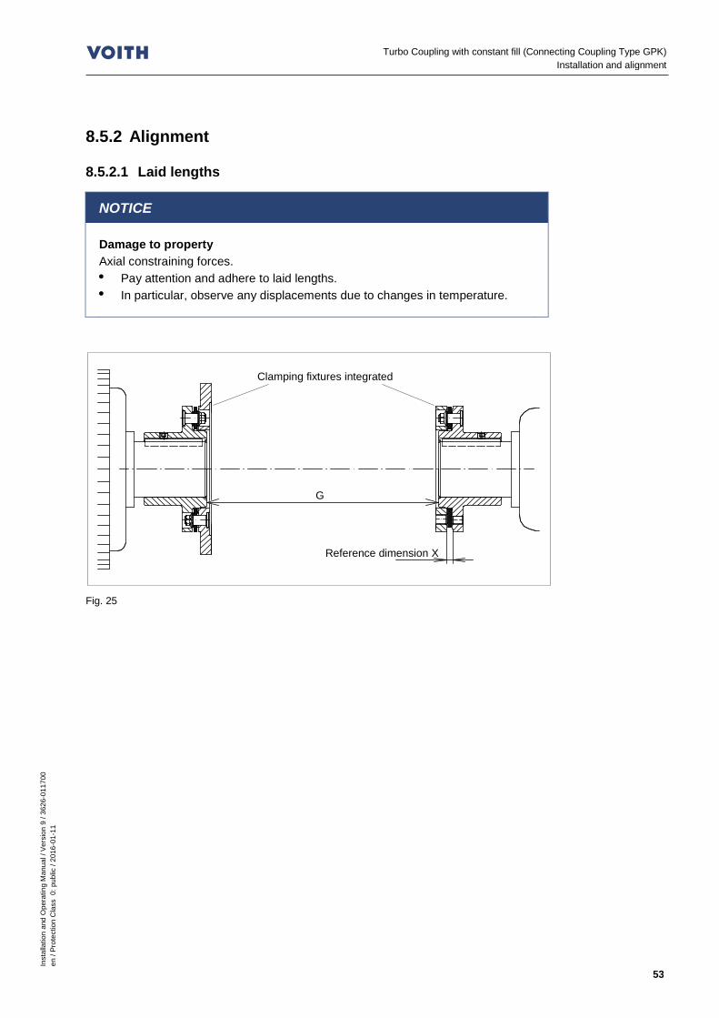
8.5.2 Alignment 8.5.2.1 Laid lengths
NOTICE
Damage to property Axial constraining forces. • Pay attention and adhere to laid lengths. • In particular, observe any displacements due to changes in temperature.
Fig. 25
G
Clamping fixtures integrated
Reference dimension X
Inst
alla
tion
and
Ope
ratin
g M
anua
l / V
ersi
on 9
/ 36
26-0
1170
0 en
/ Pr
otec
tion
Cla
ss 0
: pub
lic /
2016
-01-
11
54
Turbo Coupling with constant fill (Connecting Coupling Type GPK) Installation and alignment
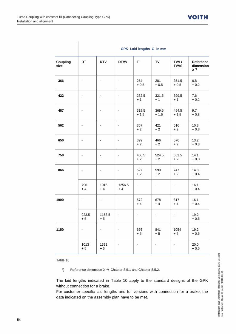
GPK Laid lengths G in mm
Coupling size
DT DTV DTVV T TV TVV / TVVS
Reference dimension X *)
366 - - - 254 + 0.5
281 + 0.5
351.5 + 0.5
6.8 + 0.2
422 - - - 282.5 + 1
321.5 + 1
399.5 + 1
7.6 + 0.2
487 - - - 318.5 + 1.5
369.5 + 1.5
454.5 + 1.5
9.7 + 0.3
562 - - - 357 + 2
421 + 2
516 + 2
10.3 + 0.3
650 - - - 399 + 2
466 + 2
576 + 2
13.2 + 0.3
750 - - - 450.5 + 2
524.5 + 2
651.5 + 2
14.1 + 0.3
866 - - - 527 + 2
599 + 2
747 + 2
14.8 + 0.4
796 + 4
1016 + 4
1256.5 + 4
- - - 16.1 + 0.4
1000 - - - 572 + 4
678 + 4
817 + 4
16.1 + 0.4
923.5 + 5
1168.5 + 5
- - - - 19.2 + 0.5
1150 - - - 676 + 5
841 + 5
1054 + 5
19.2 + 0.5
1013 + 5
1391 + 5
- - - - 20.0 + 0.5
Table 10
*) Reference dimension X Chapter 8.5.1 and Chapter 8.5.2. The laid lengths indicated in Table 10 apply to the standard designs of the GPK without connection for a brake. For customer-specific laid lengths and for versions with connection for a brake, the data indicated on the assembly plan have to be met.

Inst
alla
tion
and
Ope
ratin
g M
anua
l / V
ersi
on 9
/ 36
26-0
1170
0 en
/ Pr
otec
tion
Cla
ss 0
: pub
lic /
2016
-01-
11
55
Turbo Coupling with constant fill (Connecting Coupling Type GPK) Installation and alignment
8.5.2.2 Displacement values
WARNING
Explosion hazard Explosion hazard due to damage to the material caused by excessive misalignments. • Keep within the permissible tolerances for true radial and axial running during
all operating conditions. • In particular, observe any displacements due to changes in temperature.
SAFETY INFORMATION
Misalignments The smaller the alignment error, the • the higher the lifetime and reliability of the machine. • the smoother the operation.
The maximum permissible displacement values apply to: – the radial run-out according to the illustration in Chapter 8.5.2.3
(maximum permissible radial dial gauge deflection!). – the axial run-out according to the illustration in Chapter 8.5.2.3
(maximum permissible axial dial gauge deflection!).
GPK - maximum permissible displacement values in mm
Coupling size Radial dial gauge deflection Axial dial gauge deflection
366, 422 0.6 0.1
487 0.8 0.4
562 1.2 0.6
650, 750, 866 2.0 0.8
1000 2.0 0.8
1150 2.0 0.8
Table 11

Inst
alla
tion
and
Ope
ratin
g M
anua
l / V
ersi
on 9
/ 36
26-0
1170
0 en
/ Pr
otec
tion
Cla
ss 0
: pub
lic /
2016
-01-
11
56
Turbo Coupling with constant fill (Connecting Coupling Type GPK) Installation and alignment
8.5.2.3 Alignment
Alignment can be performed using the LASER-optical methods or manually using dial gauges ( schematic sketch below). More precise results are normally obtained using the LASER-optical methods. For alignment, support the motor feet using shims or foil sheets. It is advantageous to use claws for the adjusting screws on the foundation for lateral movement of the drive unit.
Fig. 26 • Pretension the disk packs to the reference dimension X using the hex. screws
(item 1942) ( Table 10, page 54). Do not fall below the reference dimension X.
• Provide the correct distance G between the input and output unit. • Align the input and output shaft with each other according to the above schematic
sketch (above). The displacement values of Chapter 8.5.2.2 apply.
• Securely fix the motor and gearbox (input and output unit) to the foundation. Stability depends on the whole unit and has to be guaranteed!
• Tighten all screws. • Check the alignment, and correct, if necessary.
Disk pack For illustration Page 51
Radially
Axially
Rotate the input shaft together with the fixed dial gauges!
G

Inst
alla
tion
and
Ope
ratin
g M
anua
l / V
ersi
on 9
/ 36
26-0
1170
0 en
/ Pr
otec
tion
Cla
ss 0
: pub
lic /
2016
-01-
11
57
Turbo Coupling with constant fill (Connecting Coupling Type GPK) Installation and alignment
8.5.3 Turbo coupling installation
Fig. 27
There is sufficient space for radial installation due to the axially preten-sioned disk packs.
Fig. 28
Fig. 29
• Ensure that the spacer sleeves (item 1943) of the transport protector and the
warning labels have been removed. • Fix the turbo coupling with suitable slings to a respective appliance and move it to
the input unit ( Chapter 7.4).

Inst
alla
tion
and
Ope
ratin
g M
anua
l / V
ersi
on 9
/ 36
26-0
1170
0 en
/ Pr
otec
tion
Cla
ss 0
: pub
lic /
2016
-01-
11
58
Turbo Coupling with constant fill (Connecting Coupling Type GPK) Installation and alignment
Fig. 30
NOTICE
Damage to property Fits A / B could be damaged in case of improper assembly. • Do not tilt/cant the turbo coupling when mounting it.
Fig. 31
Hex. screw for input end
A B 1955
1830
Hex. screw for output end
Correct!
1. No gap!
Do not cant!
Incorrect!
2. Bolt!

Inst
alla
tion
and
Ope
ratin
g M
anua
l / V
ersi
on 9
/ 36
26-0
1170
0 en
/ Pr
otec
tion
Cla
ss 0
: pub
lic /
2016
-01-
11
59
Turbo Coupling with constant fill (Connecting Coupling Type GPK) Installation and alignment
• Position the turbo coupling carefully between the disk packs. Pay attention to fits A and B when inserting.
• Loosen the hex. screws (item 1942) to release the disk packs. • Insert the screws (items 1830 and 1955), but do not tighten them. • Completely remove all 4 hex. screws (item 1942) on each side. • Keep the hex. screws (item 1942) for later use (disassembly). • Tighten the screws (items 1830 and 1955) uniformly, and observe the tightening
torques! 8.5.4 Check of alignment
Fig. 32 a: Distance between the flanges of the input side disk pack. b: Distance between the flanges of the output side disk packs. amin , bmin : minimum value of a or b. amax , bmax : maximum value of a or b. ∆a: amax - amin . ∆b: bmax - bmin .
Tightening torques Chapter 3.3
a b

Inst
alla
tion
and
Ope
ratin
g M
anua
l / V
ersi
on 9
/ 36
26-0
1170
0 en
/ Pr
otec
tion
Cla
ss 0
: pub
lic /
2016
-01-
11
60
Turbo Coupling with constant fill (Connecting Coupling Type GPK) Installation and alignment
• Measure a and b going around the whole periphery of the respective disk pack in 45° steps, without rotating the shafts or the turbo coupling.
• Compare the measured values with the following table:
GPK - dimensions to check the alignment in mm
Coupling size and type
a = b ∆a = ∆b
366 T… 9.50 ... 10.15 ≤ 0.4
422 T… 10.40 ... 11.30 ≤ 0.4
487 T… 12.75 ... 14.65 ≤ 1.2
562 T… 13.25 ... 15.95 ≤ 1.7
650 T… 16.20 ... 19.70 ≤ 2.5
750 T… 17.50 ... 21.00 ≤ 2.5
866 T… 19.00 ... 22.50 ≤ 2.5
866 DT… 20.50 ... 24.80 ≤ 2.3
1000 T… 20.50 ... 25.00 ≤ 2.5
1000 DT… 24.00 ... 29.00 ≤ 2.5
1150 T… 24.00 ... 29.10 ≤ 2.6
1150 DT… 25.00 ... 30.00 ≤ 2.5
Table 12 Observe the dimensions a, ∆a, b and ∆b for all operating conditions! • Fill in the assembly check report.
Protocols/reports Chapter 14
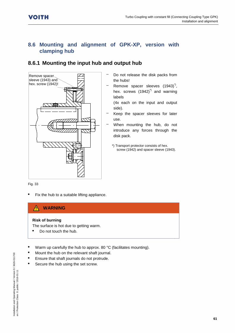
Inst
alla
tion
and
Ope
ratin
g M
anua
l / V
ersi
on 9
/ 36
26-0
1170
0 en
/ Pr
otec
tion
Cla
ss 0
: pub
lic /
2016
-01-
11
61
Turbo Coupling with constant fill (Connecting Coupling Type GPK) Installation and alignment
8.6 Mounting and alignment of GPK-XP, version with clamping hub
8.6.1 Mounting the input hub and output hub
Fig. 33
– Do not release the disk packs from the hubs!
– Remove spacer sleeves (1943)*), hex. screws (1942)*) and warning labels (4x each on the input and output side).
– Keep the spacer sleeves for later use.
– When mounting the hub, do not introduce any forces through the disk pack.
*) Transport protector consists of hex.
screw (1942) and spacer sleeve (1943).
• Fix the hub to a suitable lifting appliance.
WARNING
Risk of burning The surface is hot due to getting warm. • Do not touch the hub.
• Warm up carefully the hub to approx. 80 °C (facilitates mounting). • Mount the hub on the relevant shaft journal. • Ensure that shaft journals do not protrude. • Secure the hub using the set screw.
Remove spacer sleeve (1943) and hex. screw (1942)!

Inst
alla
tion
and
Ope
ratin
g M
anua
l / V
ersi
on 9
/ 36
26-0
1170
0 en
/ Pr
otec
tion
Cla
ss 0
: pub
lic /
2016
-01-
11
62
Turbo Coupling with constant fill (Connecting Coupling Type GPK) Installation and alignment
8.6.2 Alignment 8.6.2.1 Laid lengths
NOTICE
Damage to property Axial constraining forces. • Pay attention and adhere to laid lengths. • In particular, observe any displacements due to changes in temperature.
Fig. 34
G
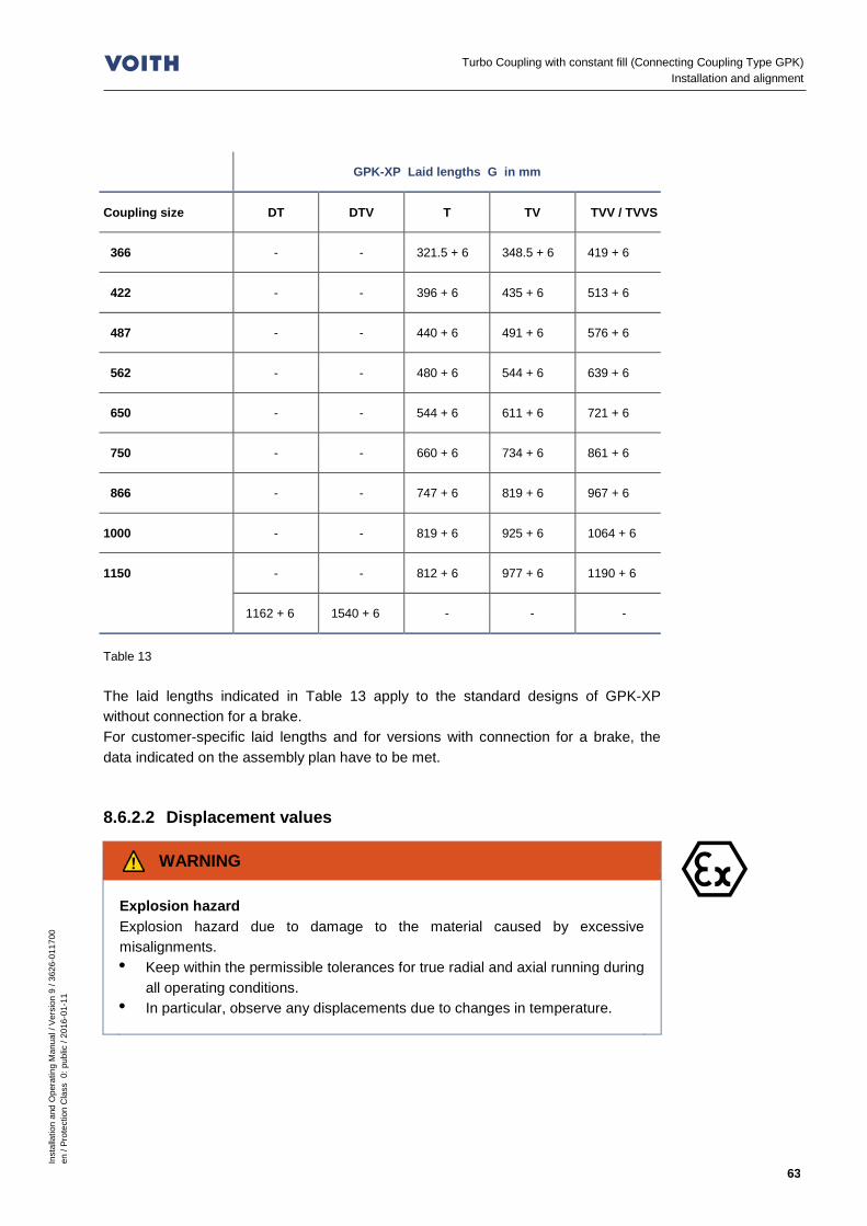
Inst
alla
tion
and
Ope
ratin
g M
anua
l / V
ersi
on 9
/ 36
26-0
1170
0 en
/ Pr
otec
tion
Cla
ss 0
: pub
lic /
2016
-01-
11
63
Turbo Coupling with constant fill (Connecting Coupling Type GPK) Installation and alignment
GPK-XP Laid lengths G in mm
Coupling size DT DTV T TV TVV / TVVS
366 - - 321.5 + 6 348.5 + 6 419 + 6
422 - - 396 + 6 435 + 6 513 + 6
487 - - 440 + 6 491 + 6 576 + 6
562 - - 480 + 6 544 + 6 639 + 6
650 - - 544 + 6 611 + 6 721 + 6
750 - - 660 + 6 734 + 6 861 + 6
866 - - 747 + 6 819 + 6 967 + 6
1000 - - 819 + 6 925 + 6 1064 + 6
1150 - - 812 + 6 977 + 6 1190 + 6
1162 + 6 1540 + 6 - - -
Table 13 The laid lengths indicated in Table 13 apply to the standard designs of GPK-XP without connection for a brake. For customer-specific laid lengths and for versions with connection for a brake, the data indicated on the assembly plan have to be met. 8.6.2.2 Displacement values
WARNING
Explosion hazard Explosion hazard due to damage to the material caused by excessive misalignments. • Keep within the permissible tolerances for true radial and axial running during
all operating conditions. • In particular, observe any displacements due to changes in temperature.

Inst
alla
tion
and
Ope
ratin
g M
anua
l / V
ersi
on 9
/ 36
26-0
1170
0 en
/ Pr
otec
tion
Cla
ss 0
: pub
lic /
2016
-01-
11
64
Turbo Coupling with constant fill (Connecting Coupling Type GPK) Installation and alignment
NOTICE
Misalignments The smaller the alignment error, the • the higher the lifetime and reliability of the machine. • the smoother the operation.
The maximum permissible displacement values apply to: – the radial run-out according to the illustration in Chapter 8.6.2.3
(maximum permissible radial dial gauge deflection!). – the axial run-out according to the illustration in Chapter 8.6.2.3
(maximum permissible axial dial gauge deflection!).
GPK-XP - maximum permissible displacement values in mm
Coupling size Radial dial gauge deflection Axial dial gauge deflection
366, 422 1.0 0.4
487 2.0 0.4
562 2.0 0.6
650, 750, 866 2.0 0.8
1000 2.0 0.8
1150 2.0 0.8
Table 14
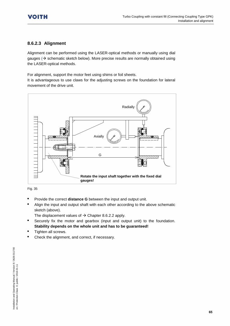
Inst
alla
tion
and
Ope
ratin
g M
anua
l / V
ersi
on 9
/ 36
26-0
1170
0 en
/ Pr
otec
tion
Cla
ss 0
: pub
lic /
2016
-01-
11
65
Turbo Coupling with constant fill (Connecting Coupling Type GPK) Installation and alignment
8.6.2.3 Alignment
Alignment can be performed using the LASER-optical methods or manually using dial gauges ( schematic sketch below). More precise results are normally obtained using the LASER-optical methods. For alignment, support the motor feet using shims or foil sheets. It is advantageous to use claws for the adjusting screws on the foundation for lateral movement of the drive unit.
Fig. 35 • Provide the correct distance G between the input and output unit. • Align the input and output shaft with each other according to the above schematic
sketch (above). The displacement values of Chapter 8.6.2.2 apply.
• Securely fix the motor and gearbox (input and output unit) to the foundation. Stability depends on the whole unit and has to be guaranteed!
• Tighten all screws. • Check the alignment, and correct, if necessary.
Radially
Axially
Rotate the input shaft together with the fixed dial gauges!
G
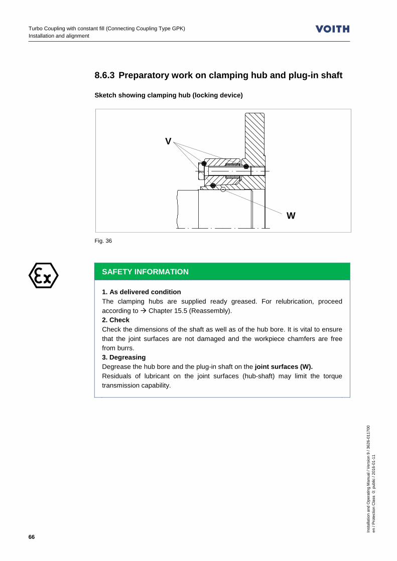
Inst
alla
tion
and
Ope
ratin
g M
anua
l / V
ersi
on 9
/ 36
26-0
1170
0 en
/ Pr
otec
tion
Cla
ss 0
: pub
lic /
2016
-01-
11
66
Turbo Coupling with constant fill (Connecting Coupling Type GPK) Installation and alignment
8.6.3 Preparatory work on clamping hub and plug-in shaft Sketch showing clamping hub (locking device)
Fig. 36
SAFETY INFORMATION
1. As delivered condition The clamping hubs are supplied ready greased. For relubrication, proceed according to Chapter 15.5 (Reassembly). 2. Check Check the dimensions of the shaft as well as of the hub bore. It is vital to ensure that the joint surfaces are not damaged and the workpiece chamfers are free from burrs. 3. Degreasing Degrease the hub bore and the plug-in shaft on the joint surfaces (W). Residuals of lubricant on the joint surfaces (hub-shaft) may limit the torque transmission capability.
W
V

Inst
alla
tion
and
Ope
ratin
g M
anua
l / V
ersi
on 9
/ 36
26-0
1170
0 en
/ Pr
otec
tion
Cla
ss 0
: pub
lic /
2016
-01-
11
67
Turbo Coupling with constant fill (Connecting Coupling Type GPK) Installation and alignment
8.6.4 Turbo coupling installation Prior to mounting, slide the clamping hub on the plug-in shaft.
Fig. 37
There is sufficient space for radial installation by the axially put back clamping hub.
Fig. 38
Fig. 39
• Ensure that all hex. screws (1942), spacer sleeves (item 1943) of the transport
protector and the warning labels have been removed. • Fix the turbo coupling with suitable slings to a respective appliance and move it to
the input unit ( Chapter 7.4).

Inst
alla
tion
and
Ope
ratin
g M
anua
l / V
ersi
on 9
/ 36
26-0
1170
0 en
/ Pr
otec
tion
Cla
ss 0
: pub
lic /
2016
-01-
11
68
Turbo Coupling with constant fill (Connecting Coupling Type GPK) Installation and alignment
Fig. 40
NOTICE
Damage to property Fits A / B could be damaged in case of improper assembly. • Do not tilt/cant the turbo coupling when mounting it.
Fig. 41
B
1946
A
1955
1830
1945
Hex. screw and spacer sleeve for input side
Do not cant!
1. No gap!
2. Bolt!
Correct! Incorrect!
Hex. screw and spacer sleeve for output side

Inst
alla
tion
and
Ope
ratin
g M
anua
l / V
ersi
on 9
/ 36
26-0
1170
0 en
/ Pr
otec
tion
Cla
ss 0
: pub
lic /
2016
-01-
11
69
Turbo Coupling with constant fill (Connecting Coupling Type GPK) Installation and alignment
• Carefully position the turbo coupling between the input and output hubs. When doing so, pay attention to fit A.
• Insert the screws (item 1830), but do not tighten. • Axially displace the clamping hub (item 1945) and pay attention to fit B on the
flange. • Ensure that the clamping hub is in the right position on the shaft. • Insert the screws (item 1955), but do not tighten. • Tighten the screws (items 1830 and 1955) uniformly, and observe the tightening
torques!
WARNING
Explosion hazard Friction heat occurs when the clamping hub slips. Please observe the following instructions: • Tighten the tensioning screws (item 1946) using a torque wrench to about
10% of the tightening torque specified in the table until the clamping hub is centered.
• Use a torque wrench to tighten the tensioning screws one after the other - NOT criss-crossing - with increasing torque, starting with about 10% of the tightening torque specified in the table, until all screws were tightened with 10% of the torque.
• Then repeat the procedure applying the 20%, 40%, 60%, 80% tightening torque.
• The tightening procedure is finished when all screws were tightened with the torque specified in the table.
8.6.5 Check of alignment
Fig. 42
Tightening torques Chapter 3.3
a b

Inst
alla
tion
and
Ope
ratin
g M
anua
l / V
ersi
on 9
/ 36
26-0
1170
0 en
/ Pr
otec
tion
Cla
ss 0
: pub
lic /
2016
-01-
11
70
Turbo Coupling with constant fill (Connecting Coupling Type GPK) Installation and alignment
a: Distance between the flanges of the input side disk pack. b: Distance between the flanges of the output side disk packs. amin , bmin : minimum value of a or b. amax , bmax : maximum value of a or b. ∆a: amax - amin . ∆b: bmax - bmin . • Measure a and b going around the whole periphery of the respective disk pack in
45° steps, without rotating the shafts or the turbo coupling. • Compare the measured values with the following table:
GPK-XP - dimensions to check the alignment in mm
Coupling size and type
a = b ∆a = ∆b
366 T… 8.50 ... 9.60 ≤ 1.1
422 T… 9.50 ... 10.60 ≤ 1.1
487 T… 12.00 ... 13.40 ≤ 1.4
562 T… 13.00 ... 14.80 ≤ 1.8
650 T… 16.20 ... 18.50 ≤ 2.3
750 T… 17.50 ... 19.80 ≤ 2.3
866 T… 18.50 ... 20.80 ≤ 2.3
1000 T… 20.50 ... 22.80 ≤ 2.3
1150 T… 24.00 ... 26.60 ≤ 2.6
1150 DT… 25.00 ... 27.40 ≤ 2.4
Table 15 Observe the dimensions a and b, ∆a and ∆b for all operating conditions! • Fill in the assembly check report.
Protocols/reports Chapter 14
Inst
alla
tion
and
Ope
ratin
g M
anua
l / V
ersi
on 9
/ 36
26-0
1170
0 en
/ Pr
otec
tion
Cla
ss 0
: pub
lic /
2016
-01-
11
71
Turbo Coupling with constant fill (Connecting Coupling Type GPK) Operating fluids
9 Operating fluids WARNING
Risk of injury Hot operating fluid could spray off from defective components or fusible plugs, seriously injuring persons! • Maintain the turbo coupling regularly! • Experts only are allowed to work on the turbo coupling!
NOTICE
Damage to property Use only the operating fluid for the turbo coupling which is indicated on the cover sheet! • Unsuitable operating fluids may damage the turbo coupling permanently! • Consult Voith Turbo if you want to use an operating fluid not mentioned.
NOTICE
Environmental pollution Operating fluids are detrimental to health and may pollute the environment. • Dispose of used operating fluid via an authorized collecting station in
accordance with the national statutory provisions. • Make sure that no operating fluid gets into the ground or water!
SAFETY INFORMATION
The values mentioned for the pour point, flash and fire point are approximate values and data originating from the oil suppliers. These may vary and Voith Turbo does not assume any warranty! Country-specific production of the basic oil may result in different values. • We recommend comparing the data with out specifications at any rate. • In case of deviations, we urgently recommend consulting the respective oil
producer.

Inst
alla
tion
and
Ope
ratin
g M
anua
l / V
ersi
on 9
/ 36
26-0
1170
0 en
/ Pr
otec
tion
Cla
ss 0
: pub
lic /
2016
-01-
11
72
Turbo Coupling with constant fill (Connecting Coupling Type GPK) Operating fluids
9.1 Requirements to be fulfilled by the operating fluid 'mineral oil'
Requirement to
Viscosity class ISO VG 32 acc. to DIN ISO 3448 *)
Viscosity on start-up less than 15000 mm2/s (cSt)
Pour point 4 °C below the minimum ambient temperature or lower
Flash point greater than 180 °C and at least 40 °C above the nominal response temperature of the fusible plugs
Resistance to aging aging-resistant refined product
Cleanliness grade Minimum requirements: 21/19/16 acc. to ISO 4406
Sealing compatibility NBR (Nitril-Butadien caoutchouc) and FPM/FKM (fluor caoutchouc)
Fire point at least 50 °C above the max. surface temperature ( Chapter 2)
*) In special cases, ISO VG 10 - 46 can be used
Advantageous additional qualities Check for Abrasion of rolling elements < 30 mg FE 8: D7,5 / 80-80 Abrasion of cage <100 mg 9.1.1 Usable operating fluids – Hydraulic oils HLP 32 to DIN 51524, Part 2 *) – Lubricating oils CLP 32 to DIN 51517, Part 3 – Steam turbine oils LTD 32 to DIN 51515, Part 1 *) – HD engine oils SAE 10 W – ATF type A Suffix A (TASA) and type Dexron II, IID, IIE, III, MERCON – M 891205 and M 921253
*) In special cases, ISO VG 10 - 46 can be used 9.1.2 Operating temperature frequently above 100 °C FPM/FKM is recommended as sealing material; when selecting the mineral oil, ensure that it provides excellent oxidation resistance. This is ensured if original Voith sealings are used.

Inst
alla
tion
and
Ope
ratin
g M
anua
l / V
ersi
on 9
/ 36
26-0
1170
0 en
/ Pr
otec
tion
Cla
ss 0
: pub
lic /
2016
-01-
11
73
Turbo Coupling with constant fill (Connecting Coupling Type GPK) Operating fluids
9.1.3 Proposed operating fluids
Producer Designation Pour point in °C
Flash point in °C
Fire point in °C
Class FE8 Test fulfilled
Addinol Hydraulic oil HLP 32 -21 195 - HLP -
Agip Agip Oso 32 Agip Blasia 32
-30 -29
204 215
260 265
HLP CLP
-
Avia Avia Fluid RSL 32 Gear RSX 32 S
-27 -33
214 210
237 231
HLP CLP
-
Castrol Alpha EP 32 Alpha VT 32 Hyspin ZZ 32 Hyspin AWS 32
-27 -42 -30 -27
218 234 216 200
250 252 238 -
CLP CLP HLP HLP
JA JA JA -
Cepsa HIDROSIC HLP 32 EP 125
-24 -30
204 206
316 316
HLP HLP
- -
Exxon Mobil
DTE 24 Mobilfluid 125 Mobil SHC 524
-27 -30 -54
220 225 234
- - 234
HLP CLP/HLP HLP
- - -
Fuchs Renolin MR10 Renolin B10
-30 -24
210 205
- -
HLP HLP
- -
Klüber Lamora HLP 32 -18 200 - HLP -
Kuwait Petroleum
Q8 Haydn 32 Q8 Holst 32
-30 -30
208 208
232 234
HLP HLP
- -
Ravenol Hydr. oil TS32 -24 220 - HLP -
Shell Tegula V32 Tellus S3 M 32 Tellus S4 ME 32
-33 -39 -54
211 236 240
- - -
HLP HLP HLP
JA - -
SRS – Salzbergen
Wintershall Wiolan HS 32 Wintershall Wiolan HF 32
-24 -27
220 200
240 240
HLP HLP
- JA
Texaco Rando HD 32 -30 196 246 HLP -
Total Azolla ZS 32 Azolla VTR 32 Preslia GT
-27 -36 -15
210 230 225
220 - -
HLP CLPD LTD
- JA JA
Table 16 The above oil list is a recommendation and does not claim to be complete.
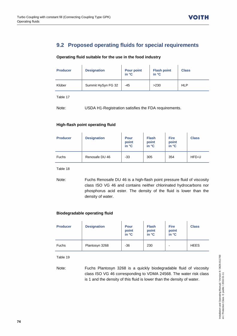
Inst
alla
tion
and
Ope
ratin
g M
anua
l / V
ersi
on 9
/ 36
26-0
1170
0 en
/ Pr
otec
tion
Cla
ss 0
: pub
lic /
2016
-01-
11
74
Turbo Coupling with constant fill (Connecting Coupling Type GPK) Operating fluids
9.2 Proposed operating fluids for special requirements Operating fluid suitable for the use in the food industry
Producer Designation Pour point in °C
Flash point in °C
Class
Klüber Summit HySyn FG 32 -45 >230 HLP
Table 17 Note: USDA H1-Registration satisfies the FDA requirements. High-flash point operating fluid
Producer Designation Pour point in °C
Flash point in °C
Fire point in °C
Class
Fuchs Renosafe DU 46 -33 305 354 HFD-U
Table 18 Note: Fuchs Renosafe DU 46 is a high-flash point pressure fluid of viscosity
class ISO VG 46 and contains neither chlorinated hydrocarbons nor phosphorus acid ester. The density of the fluid is lower than the density of water.
Biodegradable operating fluid
Producer Designation Pour point in °C
Flash point in °C
Fire point in °C
Class
Fuchs Plantosyn 3268 -36 230 - HEES
Table 19 Note: Fuchs Plantosyn 3268 is a quickly biodegradable fluid of viscosity
class ISO VG 46 corresponding to VDMA 24568. The water risk class is 1 and the density of this fluid is lower than the density of water.

Inst
alla
tion
and
Ope
ratin
g M
anua
l / V
ersi
on 9
/ 36
26-0
1170
0 en
/ Pr
otec
tion
Cla
ss 0
: pub
lic /
2016
-01-
11
75
Turbo Coupling with constant fill (Connecting Coupling Type GPK) Operating fluids
9.3 Requirements to be fulfilled by the operating fluid 'water'
Requirement to
Sealing compatibility NBR (Nitril-Butadien caoutchouc)
ph value 5…8
The water used should – to the greatest possible extent, be free from solid matters, – contain only a low amount of salt, – contain only a low concentration of other additives. 9.3.1 Usable operating fluids Normally, drinking water satisfies these requirements.
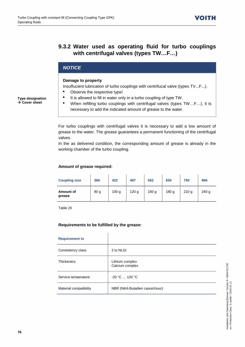
Inst
alla
tion
and
Ope
ratin
g M
anua
l / V
ersi
on 9
/ 36
26-0
1170
0 en
/ Pr
otec
tion
Cla
ss 0
: pub
lic /
2016
-01-
11
76
Turbo Coupling with constant fill (Connecting Coupling Type GPK) Operating fluids
9.3.2 Water used as operating fluid for turbo couplings with centrifugal valves (types TW…F…)
NOTICE
Damage to property Insuffucient lubrication of turbo couplings with centrifucal valve (types TV...F...). • Observe the respective type! • It is allowed to fill in water only in a turbo coupling of type TW. • When refilling turbo couplings with centrifugal valves (types TW…F…), it is
necessary to add the indicated amount of grease to the water.
For turbo couplings with centrifugal valves it is necessary to add a low amount of grease to the water. The grease guarantees a permanent functioning of the centrifugal valves. In the as delivered condition, the corresponding amount of grease is already in the working chamber of the turbo coupling. Amount of grease required:
Coupling size 366 422 487 562 650 750 866
Amount of grease
80 g 100 g 120 g 150 g 180 g 210 g 240 g
Table 20 Requirements to be fulfilled by the grease:
Requirement to
Consistency class 2 to NLGI
Thickeners Lithium complex Calcium complex
Service temperature -20 °C … 120 °C
Material compatibility NBR (Nitril-Butadien caoutchouc)
Type designation Cover sheet
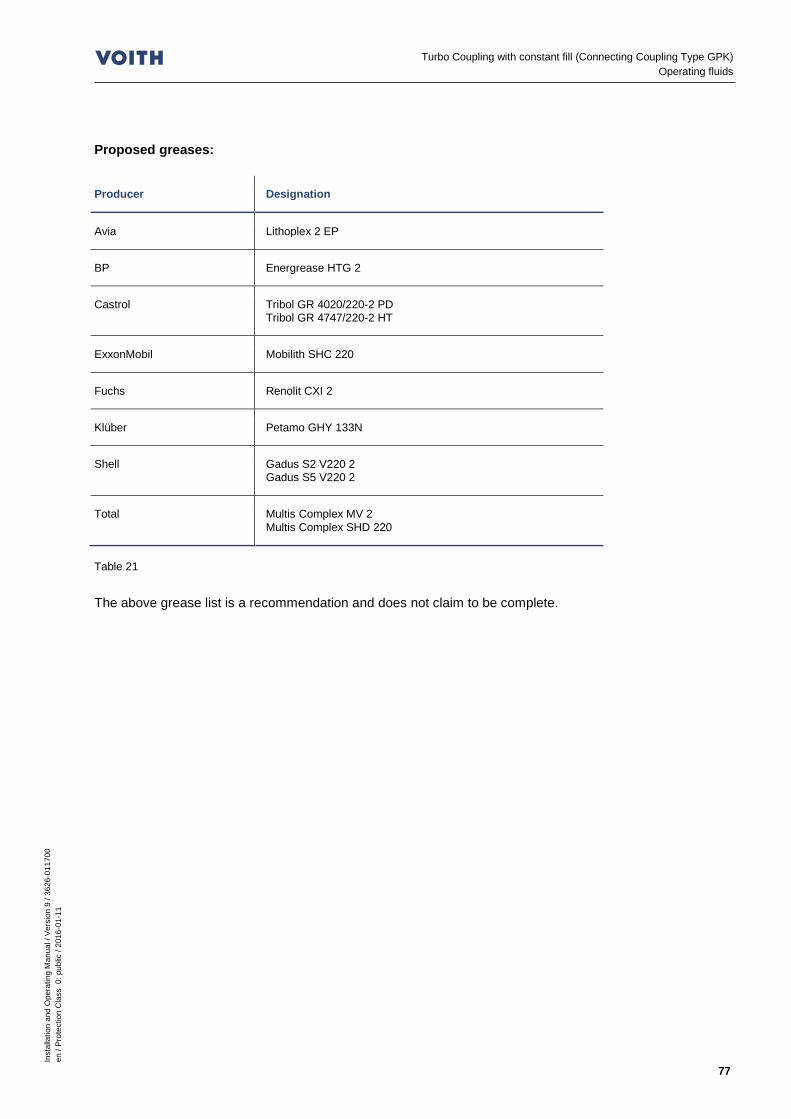
Inst
alla
tion
and
Ope
ratin
g M
anua
l / V
ersi
on 9
/ 36
26-0
1170
0 en
/ Pr
otec
tion
Cla
ss 0
: pub
lic /
2016
-01-
11
77
Turbo Coupling with constant fill (Connecting Coupling Type GPK) Operating fluids
Proposed greases:
Producer Designation
Avia Lithoplex 2 EP
BP Energrease HTG 2
Castrol Tribol GR 4020/220-2 PD Tribol GR 4747/220-2 HT
ExxonMobil Mobilith SHC 220
Fuchs Renolit CXI 2
Klüber Petamo GHY 133N
Shell Gadus S2 V220 2 Gadus S5 V220 2
Total Multis Complex MV 2 Multis Complex SHD 220
Table 21 The above grease list is a recommendation and does not claim to be complete.

Inst
alla
tion
and
Ope
ratin
g M
anua
l / V
ersi
on 9
/ 36
26-0
1170
0 en
/ Pr
otec
tion
Cla
ss 0
: pub
lic /
2016
-01-
11
78
Turbo Coupling with constant fill (Connecting Coupling Type GPK) Filling, Filling Check and Draining
10 Filling, Filling Check and Draining
The quantity and type of operating fluid used substantially determines the performance of the turbo coupling. – A too high quantity stresses the drive motor more on start-up and results in a
higher stall torque. – A too low quantity thermally loads the turbo coupling more and results in a lower
stall torque.
WARNING
Risk of burning The turbo coupling gets warm during operation. • Please observe, in particular, Chapter 6 (Safety) when working on the
turbo coupling! • Start to work on the turbo coupling only after it has cooled down to below
44 °C.
CAUTION
Danger to health Operating fluids may cause irritations or inflammation if coming into contact with skin and mucous membranes. • Please pay attention to the information contained in the safety data sheets. • Please always wear safety goggles when working with the operating fluid! • Should you get any operating fluid in your eyes, rinse them immediately
using plenty of water and consult a physician without delay! • After finishing work, carefully clean your hands with soap.
NOTICE
Damage to property Insufficient lubrication • When refilling turbo couplings with centrifugal valves (types TW…F…), it is
necessary to add the indicated amount of grease to the water.

Inst
alla
tion
and
Ope
ratin
g M
anua
l / V
ersi
on 9
/ 36
26-0
1170
0 en
/ Pr
otec
tion
Cla
ss 0
: pub
lic /
2016
-01-
11
79
Turbo Coupling with constant fill (Connecting Coupling Type GPK) Filling, Filling Check and Draining
Impurities in the operating fluid cause higher wear on the coupling as well as damages to bearings so that explosion protection can no longer be guaranteed. – Make sure that any containers, funnels, filling tubes, etc. used for filling the
coupling, are clean.
NOTICE
Damage to property Non-compliance with specifications. • Observe the quantity to be filled in that is indicated on the cover sheet of this
operating manual. • An overfilling is not permitted! This would lead to an undue high internal
pressure in the coupling, which may destroy the coupling. • An underfilling is not permitted! This will result in an improper operation of the
coupling. • Do not mix different types of operating fluids. • Use only the operating fluid indicated on the cover sheet of this manual. • Ensure that the original sealing rings used are in sound condition.
10.1 Filling the turbo coupling
SAFETY INFORMATION
Turbo couplings are shipped unfilled. • If operating fluid is included in the scope of supply, it is shipped in a separate
container.
• Turn the turbo coupling until the filler plug (item 0390) that is closest to the sight
glass (item 0396) is on top. • Remove the filler plug. • Remove the top fusible plug (item 0395 or item 0260) for pressure compensation. • For turbo couplings with centrifugal valves (type TW...F...), fill in the specified
amount of grease into the working chamber of the turbo coupling. • Fill in the specified quantity of operating fluid ( Chapter 9) through a fine strainer
- mesh size ≤ 25 µm for turbo couplings using oil and operating medium (type T...)
- mesh size ≤ 50 µm for turbo couplings using water as operating medium (type TW…)
via the opening in the filler plug. • Tighten the filler plug. • Tighten the fusible plug.
Amount of grease Chapter 9.3.2 Operating fluid and filling volume Cover sheet
Tightening torques Chapter 3.2
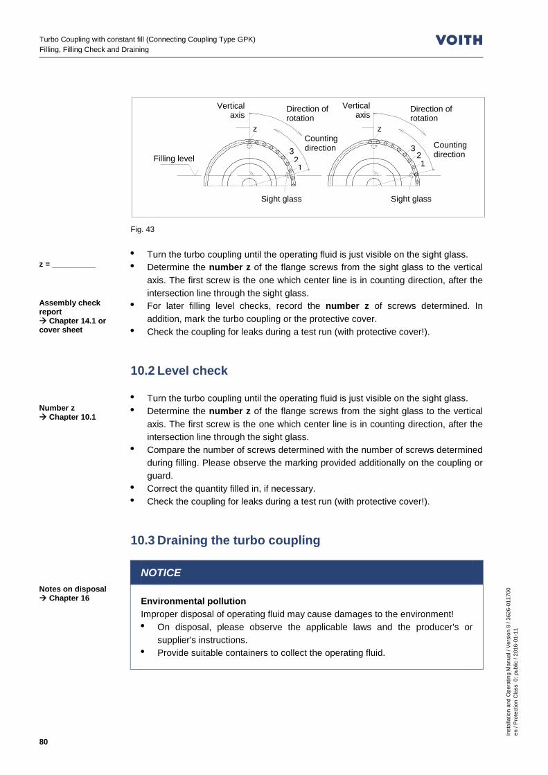
Inst
alla
tion
and
Ope
ratin
g M
anua
l / V
ersi
on 9
/ 36
26-0
1170
0 en
/ Pr
otec
tion
Cla
ss 0
: pub
lic /
2016
-01-
11
80
Turbo Coupling with constant fill (Connecting Coupling Type GPK) Filling, Filling Check and Draining
Fig. 43 • Turn the turbo coupling until the operating fluid is just visible on the sight glass. • Determine the number z of the flange screws from the sight glass to the vertical
axis. The first screw is the one which center line is in counting direction, after the intersection line through the sight glass.
• For later filling level checks, record the number z of screws determined. In addition, mark the turbo coupling or the protective cover.
• Check the coupling for leaks during a test run (with protective cover!). 10.2 Level check • Turn the turbo coupling until the operating fluid is just visible on the sight glass. • Determine the number z of the flange screws from the sight glass to the vertical
axis. The first screw is the one which center line is in counting direction, after the intersection line through the sight glass.
• Compare the number of screws determined with the number of screws determined during filling. Please observe the marking provided additionally on the coupling or guard.
• Correct the quantity filled in, if necessary. • Check the coupling for leaks during a test run (with protective cover!). 10.3 Draining the turbo coupling
NOTICE
Environmental pollution Improper disposal of operating fluid may cause damages to the environment! • On disposal, please observe the applicable laws and the producer's or
supplier's instructions. • Provide suitable containers to collect the operating fluid.
z = __________
Assembly check report Chapter 14.1 or cover sheet
Number z Chapter 10.1
Notes on disposal Chapter 16
Sight glass Sight glass
Vertical axis
Vertical axis
Counting direction
Counting direction
Direction of rotation
1
z z
3 3 2 2
1
Direction of rotation
Filling level

Inst
alla
tion
and
Ope
ratin
g M
anua
l / V
ersi
on 9
/ 36
26-0
1170
0 en
/ Pr
otec
tion
Cla
ss 0
: pub
lic /
2016
-01-
11
81
Turbo Coupling with constant fill (Connecting Coupling Type GPK) Filling, Filling Check and Draining
10.3.1 Draining of turbo couplings without delay chamber installed in horizontal position
• Put a catch pan underneath. • Turn the turbo coupling until one fusible plug it at the bottom. • Remove this fusible plug. • For aeration, remove one opposite fillter of fusible plug. • The operating fluids flows out from the turbo coupling. • Wait until no more operating fluid comes out. • Only use original seals. • Re-tighten all screws. 10.3.2 Draining of turbo couplings with delay chamber
installed in horizontal position • Put a catch pan underneath. • Turn the turbo coupling until one fusible plug it at the bottom. • Remove this fusible plug. • For aeration, remove one opposite fillter of fusible plug. • The operating fluid flows out from the working chamber of the turbo coupling. • Wait until no more operating fluid comes out. • Remove the nozzle screw (item 0455 / 0456). • Turn the turbo coupling until the opening of the nozzle screw is at the bottom. • The operating fluid flows out from the delay chamber of the turbo coupling. • Wait until no more operating fluid comes out. • Only use original seals. • Tighten the nozzle screw. • Turn the turbo coupling until the opening of the fusible plug is at the bottom. • The remaining operating fluid flows out from the working chamber of the turbo
coupling. • Wait until no more operating fluid comes out. • Only use original seals. • Re-tighten all screws.
Tightening torques Chapter 3.2
Tightening torques Chapter 3.2

Inst
alla
tion
and
Ope
ratin
g M
anua
l / V
ersi
on 9
/ 36
26-0
1170
0 en
/ Pr
otec
tion
Cla
ss 0
: pub
lic /
2016
-01-
11
82
Turbo Coupling with constant fill (Connecting Coupling Type GPK) Commissioning
11 Commissioning WARNING
Risk of injury Please observe, in particular, Chapter 6 (Safety) when working on the turbo coupling! • Before beginning with commissioning, ensure that the transport protectors
(hex. screw (1942) and spacer sleeve (1943)) have been removed! • A commissioning not performed properly could cause injury to persons, or
harm to property and the environment! • Experts only are allowed to perform commissioning, in particular, first starting
of the turbo coupling! • Secure the machine against unintentional switching on!
Explosion hazard – Please check with reference to the marking whether the turbo coupling is
approved for use in potentially explosive atmospheres. – Provide the turbo coupling with a protective cover (e.g. perforated sheet, size of
holes approx. 10 – 12 mm). This protective cover has to • prevent intrusion of damaging foreign particles (stones, corrosive steels, etc.). • withstand expected impacts without any major damages, thus preventing
contact of the turbo coupling with the protective cover. Especially turbo couplings with outer parts made of aluminum must not get in contact with corrosive steel or iron.
• collect spraying solder of fusible plugs. • collect any operating fluid leaking out to prevent contact with parts (motor, belt)
that might ignite or catch fire. • provide sufficient ventilation to maintain the maximum surface temperature
specified. A perforated sheet with 65% hole cross section enclosing the coupling on all sides does not reduce the ventilation (consult Voith Turbo, if necessary).
• guarantee safety distances to prevent hazard zones from being reached (DIN EN ISO 13857).
For constructional proposals for protective covers, please contact Voith Turbo.
Marking Chapter 6.2

Inst
alla
tion
and
Ope
ratin
g M
anua
l / V
ersi
on 9
/ 36
26-0
1170
0 en
/ Pr
otec
tion
Cla
ss 0
: pub
lic /
2016
-01-
11
83
Turbo Coupling with constant fill (Connecting Coupling Type GPK) Commissioning
– The turbo coupling is not equipped with insulated ball and roller bearings! The passage of current and stray currents may come from connected machines (e.g. VFD motor).
– In order to avoid electrostatic charging, it is not allowed to install the turbo coupling with an insulation on both sides.
– Provide an equipotential bonding between the input and output end. – Provide machines on which overspeed is possible, with a device preventing
reliably overspeed (e.g. brake or backstop).
WARNING
Hazard by being pulled in Slack clothing, long hair, necklaces, rings or loose parts may get caught and be drawn in or wound up causing serious injuries or damage to the turbo coupling and the environment. • Only wear close-fitting clothes when working! • Cover long hair with a hair net! • Do not wear any jewelry (e.g. necklaces, rings, etc.)! • Never operate the turbo coupling without protective cover!
WARNING
Explosion hazard Explosion hazard due to frictional heat or overheating. • Ensure that the disks of the connecting coupling (type GPK) do not touch the
flanges. • If you use a BTS-Ex to limit the maximum surface temperature, make sure
not to exceed the maximum permissible temperature of the turbo coupling when switching on the motor.
Technical data Chapter 2
Inst
alla
tion
and
Ope
ratin
g M
anua
l / V
ersi
on 9
/ 36
26-0
1170
0 en
/ Pr
otec
tion
Cla
ss 0
: pub
lic /
2016
-01-
11
84
Turbo Coupling with constant fill (Connecting Coupling Type GPK) Commissioning
Information with regard to commissioning – The turbo coupling may be used for any direction of rotation. – The direction of rotation of the driven machine may be specified! The direction of
rotation of the motor must be in accordance with the specified direction of rotation of the driven machine!
– If the motor is started with star/delta connection, switch over from star to delta after 2...5 seconds at the latest.
– In case of a multi-motor drive, you should determine the load of the individual motors. Great differences regarding motor load may be balanced by an appropriate adjustment of the respective coupling filling volumes. However, do not exceed the maximum permissible coupling filling level!
Commissioning • Perform all commissioning work according to the commissioning report.
Pay special attention to: - a normal machine operation - normal noise
• Record the commissioning process.
Operating fluid and filling volume Cover sheet
Commissioning report Chapter 14.2

Inst
alla
tion
and
Ope
ratin
g M
anua
l / V
ersi
on 9
/ 36
26-0
1170
0 en
/ Pr
otec
tion
Cla
ss 0
: pub
lic /
2016
-01-
11
85
Turbo Coupling with constant fill (Connecting Coupling Type GPK) Operation
12 Operation WARNING
Risk of injury Please observe, in particular, Chapter 6 (Safety) when working on the turbo coupling! • An operation presupposes the successful commissioning according to Chapter 11.
Information with regard to operation – Never operate the turbo coupling without operating fluid! – On account of the type of bearings used for standard turbo couplings, at least one
standstill is required within three months. During normal operation, no operator actions on the turbo coupling are required. Perform the necessary maintenance work time-/operating time-based according to Chapter 13. If malfunctions occur, eliminate such according to Chapter 17.

Inst
alla
tion
and
Ope
ratin
g M
anua
l / V
ersi
on 9
/ 36
26-0
1170
0 en
/ Pr
otec
tion
Cla
ss 0
: pub
lic /
2016
-01-
11
86
Turbo Coupling with constant fill (Connecting Coupling Type GPK) Maintenance, Servicing
13 Maintenance, Servicing Definition of the maintenance work described in the following (as per IEC 60079): Maintenance and Servicing: A combination of all activities conducted in order to maintain an object in a condition or to re-store it to such a condition which meets the requirements of the respective specification and ensures performance of the required functions. Inspection: An activity involving the thorough examination of an object in order to provide a reliable statement as to the condition of said object, performed without disassembly or, if necessary, with only partial disassembly, supplemented by measures such as the taking of measurements. Visual inspection: A visual inspection is an inspection in which visible defects, such as missing screws or bolts, are identified without the use of access equipment or tools. Close-up inspection: An inspection in which, in addition to the areas covered by the visual inspection, defects such as loose bolts, that can only be detected by using access equipment, e.g. mobile stair steps (if required) and tools are identified. For close-up inspections, usually a housing does not need to be opened or the power to the equipment be cut off. Detailed inspection: An inspection in which, in addition to the areas covered by the close-up inspection, defects such as loose connections, that can only be detected by opening housings and/or using tools and test equipment (if required) are identified.

Inst
alla
tion
and
Ope
ratin
g M
anua
l / V
ersi
on 9
/ 36
26-0
1170
0 en
/ Pr
otec
tion
Cla
ss 0
: pub
lic /
2016
-01-
11
87
Turbo Coupling with constant fill (Connecting Coupling Type GPK) Maintenance, Servicing
WARNING
Risk of injury Please observe, in particular, Chapter 6 (Safety) when working on the turbo coupling! • Please always keep access paths free to the turbo coupling!
– Skilled and authorized persons only are allowed to carry out maintenance and
repair work! Qualification is ensured by performing training and giving instructions on the turbo coupling.
– Possible consequences of improper servicing and maintenance could be death, serious or minor injuries, damage to property and harm to the environment.
– Switch off the unit in which the turbo coupling is installed and secure the switch against inadvertent switch-on.
– For all work performed on the turbo coupling ensure that both the drive motor and the driven machine have stopped running and that a re-start is absolutely impossible!
– Components may only be replaced by original spare parts. Re-mount all protective covers and safety devices in their original position immediately after completion of the servicing and maintenance work. Check them for proper functioning. Maintenance schedule:
Time Maintenance work
About 1 hour after commissioning Check the tightening torques of fastening screws, items 1830 and 1955.
After the first 500 operating hours Check the tightening torques of fastening screws, items 1830 and 1955. Check the steel disks of the connecting coupling ( Chapter 13.2). Check the reference dimensions a and b ( Chapters 8.5.4 and 8.6.5), compare them with the commissioning report and re-align them in case of deviations and impermissible values. For type GPK-XP (with clamping hub): Check the tightening torques of the tensioning screws, item 1946.
Qualification Chapter 6.9
Tightening torques Chapter 3.3

Inst
alla
tion
and
Ope
ratin
g M
anua
l / V
ersi
on 9
/ 36
26-0
1170
0 en
/ Pr
otec
tion
Cla
ss 0
: pub
lic /
2016
-01-
11
88
Turbo Coupling with constant fill (Connecting Coupling Type GPK) Maintenance, Servicing
Time Maintenance work
Routine inspection after 500 operating hours, every 3 months at the latest.
Inspect the machine for irregularities (visual inspection: for leaks, noise, vibrations). Check the foundation bolts of the machine, and if necessary, re-tighten them with the specified torque.
3 months after commissioning, at the latest, then every year
Check the electrical system for sound condition if temperature monitoring is required in Chapter 2 (detailed inspection).
Every 12 / 6 / 4 months for 1 / 2 / 3-shift operation
Check of disks for deformation, fractures and cracks as well as for flatness, freedom from distortion, homogeneity of pack.
When mineral oil is used as operating fluid: After every 15000 operating hous
- Change the operating fluid or check it for aging and
- determine the remaining service life (see records Chapter 14)!
Consult the operating fluid supplier with regard to the permissible values (see Chapters 9 and 10).
On response of a fusible plug Replace all fusible plugs and change the operating fluid ( Chapter 13.4). Check the operating conditions ( Chapter 2). Check the devices provided for temperature monitoring (see Chapter 19: MTS, BTS(ex), BTM).
In case of leaks On the occasion of an overhaul of the turbo coupling, have shaft sealing rings, sealing rings and flat seals replaced by skilled persons authorized by Voith.
In case of noise, vibrations Have the cause determined and eliminated by skilled persons authorized by Voith.
In case of impurities Cleaning ( Chapter 13.1).
Table 22 • Carry out any maintenance work and routine inspections according to the report. • Record the maintenance work carried out.
Report samples Chapter 14.3
Inst
alla
tion
and
Ope
ratin
g M
anua
l / V
ersi
on 9
/ 36
26-0
1170
0 en
/ Pr
otec
tion
Cla
ss 0
: pub
lic /
2016
-01-
11
89
Turbo Coupling with constant fill (Connecting Coupling Type GPK) Maintenance, Servicing
For explosion-proof turbo couplings, the following maintenance work needs to be carried out in addition:
Maintenance intervals Maintenance work
In case of impurities or dusting: Clean the turbo coupling when used in potentially explosive atmospheres in regular intervals. The intervals are specified by the operator according to the environmental impact to which the equipment is exposed on the jobsite, e.g. in case of a dust accumulation of approx. 0.2 ... 0.5 mm or more.
Cleaning ( Chapter 13.1).
Maintenance interval Chapter 2 Replacement of ball and roller bearings ( Chapter 13.3.3).
Table 23
WARNING
Explosion hazard Explosion hazard due to maintenance work not performed according to schedule. It is vital to carry out all maintenance work according to the schedule in order to guarantee proper operation within the meaning of explosion-protection. • Immediately remove any combustible layers of dust on the turbo couplings. • To ensure a good aeration of the turbo coupling, it is vital to check and clean
the protective cover in regular intervals. • If a fusible plug has responded, immediately cover or close the opening that
occurred in order to prevent the ingress of combustible dust into the turbo coupling.
13.1 Outside cleaning
NOTICE
Damage to property Damage to the turbo coupling due to an improper, unsuitable outside cleaning. • Please ensure that the cleaning agent is compatible with the sealing
materials used, NBR and FPM/FKM! • Do not use high-pressure cleaning equipment! • Be careful with gaskets. Do not apply a water and compressed-air jet.
• Clean the turbo coupling with a grease solvent, as and when required.

Inst
alla
tion
and
Ope
ratin
g M
anua
l / V
ersi
on 9
/ 36
26-0
1170
0 en
/ Pr
otec
tion
Cla
ss 0
: pub
lic /
2016
-01-
11
90
Turbo Coupling with constant fill (Connecting Coupling Type GPK) Maintenance, Servicing
13.2 Connecting coupling types GPK and GPK-XP • When inspecting the machine, check the connecting coupling for heavily deformed
disks compared to the initial installation condition, for disk fractures or signs of corrosion on disks.
• The sum of all gaps (between individual disks) must not exceed 50% of the air gap between the flange or hub and the disk pack (without torque application). Measure the gap between the flange or hub and disk pack around the washers and without torque application.
WARNING
Explosion hazard Explosion hazard due to overload or faulty alignment. Disks deformed compared to the initial installation condition, disk fractures or signs of corrosion may be an indication for overload or faulty alignment! • Replace the complete coupling half (item 1932 or 1972)! • It is not allowed to replace individual disks. Professional maintenance or
repair can only be guaranteed by the manufacturer!
13.3 Bearings 13.3.1 Bearing lubrication when mineral oil is used as
operating fluid Please observe the following in order to guarantee lubrication of the bearings:
NOTICE
Damage to property Danger of bearing damage. • On account of the type of bearings used for standard turbo couplings, at least
one standstill is required within three months.
SAFETY INFORMATION
Lifetime grease filling • Turbo couplings can be provided with special bearings that allow continuous
operation and contain a lifetime grease filling.

Inst
alla
tion
and
Ope
ratin
g M
anua
l / V
ersi
on 9
/ 36
26-0
1170
0 en
/ Pr
otec
tion
Cla
ss 0
: pub
lic /
2016
-01-
11
91
Turbo Coupling with constant fill (Connecting Coupling Type GPK) Maintenance, Servicing
13.3.2 Bearing lubrication when water is used as operating fluid
The turbo coupling bearings are filled with lifetime grease when water is used as operating fluid. Re-lubrication is not necessary. 13.3.3 Replacement of bearings / re-lubrication
SAFETY INFORMATION
On the occasion of an overhaul of the turbo couplings, have the bearings replaced / re-lubricated by skilled persons authorized by Voith.
13.4 Fusible plugs – The fusible plugs protect the turbo coupling against damage due to thermal
overload. – When the nominal response temperature is reached, the solder core of the fusible
plugs melts and the operating fluid leaks out. Fusible plugs are identified by – the engraved nominal response temperature in °C, – a color coding:
Nominal response temperature
Color coding Operating fluid Oil
Operating fluid Water
95 °C without (tinned) X X
110 °C yellow X X
125 °C brown X -
140 °C red X -
160 °C green X -
180 °C blue X -
Table 24
Replacement interval of ball and roller bearings Chapter 2
Nominal response temperature of fu-sible plugs Cover sheet

Inst
alla
tion
and
Ope
ratin
g M
anua
l / V
ersi
on 9
/ 36
26-0
1170
0 en
/ Pr
otec
tion
Cla
ss 0
: pub
lic /
2016
-01-
11
92
Turbo Coupling with constant fill (Connecting Coupling Type GPK) Maintenance, Servicing
SAFETY INFORMATION
• Use only original fusible plugs SSS-X with the required nominal response temperature!
• Do not replace any fusible plugs by blind screws! • Do not alter the arrangement of the fusible plugs. • When water is used as operating fluid, only fusible plugs with a max. nominal
response temperature of 110 °C are permitted! • Never operate the turbo coupling without fusible plugs!
SAFETY INFORMATION
Switching elements, unbalance • There is a MTS and/or BTS switching element or a blind screw opposite the
sight glass (position is marked by an arrow). • Insert a weight-tolerated BTM blind screw opposite the BTM switching
element. Do not insert the BTM switching element opposite a sight glass, blind screw or fusible plug having a lighter weight.
On response of a fusible plug: • Replace all fusible plugs. • Change the operating fluid. 13.4.1 Fusible plugs in turbo couplings not suitable for use
in potentially explosive atmospheres
SAFETY INFORMATION
• The fusible plugs for turbo couplings of type “TW“ and sizes 422, 487, 562, 650, 750, 866 and 1150 are arranged in the outer wheel.
• If a brake is used, select the position of the fusible plugs so that they do not spray onto the brake. Please check that and, if necessary, change the fusible plugs for the opposite blind screws.
Design Chapter 2
Tightening torques Chapter 3.2

Inst
alla
tion
and
Ope
ratin
g M
anua
l / V
ersi
on 9
/ 36
26-0
1170
0 en
/ Pr
otec
tion
Cla
ss 0
: pub
lic /
2016
-01-
11
93
Turbo Coupling with constant fill (Connecting Coupling Type GPK) Maintenance, Servicing
Number and position of fusible plugs, blind screws and switching elements:
Shell (item 0190)
Coupling size and type
Fusible plug Item 0260
Blind screw Item 0265
MTS, BTS switching element 1)
366 T… 1 1 - 366 TW… - 2 - 422 T… 2 - - 487 T… 2 - - 562 T… 2 - - 650 T… 3 1 4) - 750 T… 2 2 - 866 T… 3 1 4) - 866 DT… - - - 1000 T… 4 - - 1000 TW… - 4 1 1000 DT… - - - 1150 T… 4 - - 1150 DT… - - -
Outer wheel (item 0300)
Coupling size and type
Fusible plug item 0395
Blind screw item 0394
MTS, BTS, BTM 2) - switching element 1)
Sight glass 3)
Item 0396
366 T… - 5 1 1 366 TW… 2 3 1 1 422 T… - 7 1 1 487 T… - 7 1 1 562 T… - 7 1 1 650 T… - 5 1 1 750 T… - 5 1 1 866 T… - 5 1 1 866 DT… 6 5 1 1 1000 T… - 3 1 1 1000 TW… 3 - - 1 1000 DT… 6 1 1 1 1150 T… - 5 1 1 1150 DT… 8 3 1 1
Table 25
1) The MTS, BTS or BTM switching element is inserted instead of a blind screw. 2) The blind screw opposite the BTM has to be replaced by the counterweight. 3) Position is marked by an arrow. 4) Only for annular chamber (type T…S…).

Inst
alla
tion
and
Ope
ratin
g M
anua
l / V
ersi
on 9
/ 36
26-0
1170
0 en
/ Pr
otec
tion
Cla
ss 0
: pub
lic /
2016
-01-
11
94
Turbo Coupling with constant fill (Connecting Coupling Type GPK) Maintenance, Servicing
13.4.2 Fusible plugs in turbo couplings suitable for use in potentially explosive atmospheres
SAFETY INFORMATION
Thermal monitoring devices • A thermal monitoring system can prevent that operating fluid is sprayed off
( Chapter 19). • Thermal monitoring systems are available at Voith Turbo as accessories.
WARNING
Fire hazard If a brake is used, select the position of the fusible plugs so that they do not spray onto the brake. • This needs to be checked. In case of any deviation, please consult Voith
Turbo.
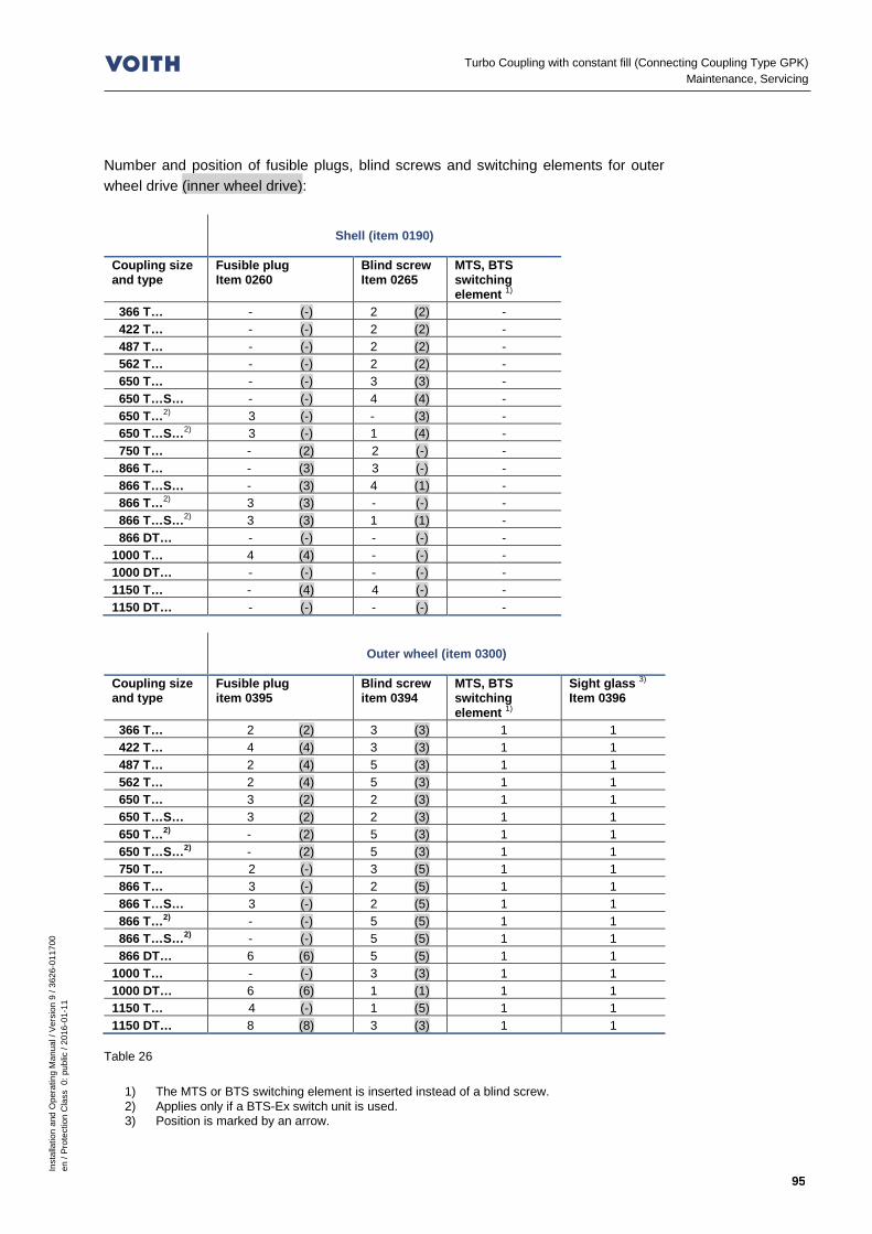
Inst
alla
tion
and
Ope
ratin
g M
anua
l / V
ersi
on 9
/ 36
26-0
1170
0 en
/ Pr
otec
tion
Cla
ss 0
: pub
lic /
2016
-01-
11
95
Turbo Coupling with constant fill (Connecting Coupling Type GPK) Maintenance, Servicing
Number and position of fusible plugs, blind screws and switching elements for outer wheel drive (inner wheel drive):
Shell (item 0190)
Coupling size and type
Fusible plug Item 0260
Blind screw Item 0265
MTS, BTS switching element 1)
366 T… - (-) 2 (2) - 422 T… - (-) 2 (2) - 487 T… - (-) 2 (2) - 562 T… - (-) 2 (2) - 650 T… - (-) 3 (3) - 650 T…S… - (-) 4 (4) - 650 T…2) 3 (-) - (3) - 650 T…S…2) 3 (-) 1 (4) - 750 T… - (2) 2 (-) - 866 T… - (3) 3 (-) - 866 T…S… - (3) 4 (1) - 866 T…2) 3 (3) - (-) - 866 T…S…2) 3 (3) 1 (1) - 866 DT… - (-) - (-) - 1000 T… 4 (4) - (-) - 1000 DT… - (-) - (-) - 1150 T… - (4) 4 (-) - 1150 DT… - (-) - (-) -
Outer wheel (item 0300)
Coupling size and type
Fusible plug item 0395
Blind screw item 0394
MTS, BTS switching element 1)
Sight glass 3)
Item 0396
366 T… 2 (2) 3 (3) 1 1 422 T… 4 (4) 3 (3) 1 1 487 T… 2 (4) 5 (3) 1 1 562 T… 2 (4) 5 (3) 1 1 650 T… 3 (2) 2 (3) 1 1 650 T…S… 3 (2) 2 (3) 1 1 650 T…2) - (2) 5 (3) 1 1 650 T…S…2) - (2) 5 (3) 1 1 750 T… 2 (-) 3 (5) 1 1 866 T… 3 (-) 2 (5) 1 1 866 T…S… 3 (-) 2 (5) 1 1 866 T…2) - (-) 5 (5) 1 1 866 T…S…2) - (-) 5 (5) 1 1 866 DT… 6 (6) 5 (5) 1 1 1000 T… - (-) 3 (3) 1 1 1000 DT… 6 (6) 1 (1) 1 1 1150 T… 4 (-) 1 (5) 1 1 1150 DT… 8 (8) 3 (3) 1 1
Table 26
1) The MTS or BTS switching element is inserted instead of a blind screw. 2) Applies only if a BTS-Ex switch unit is used. 3) Position is marked by an arrow.
Inst
alla
tion
and
Ope
ratin
g M
anua
l / V
ersi
on 9
/ 36
26-0
1170
0 en
/ Pr
otec
tion
Cla
ss 0
: pub
lic /
2016
-01-
11
96
Turbo Coupling with constant fill (Connecting Coupling Type GPK) Assembly Check-, Commissioning and Maintenance Report
14 Assembly Check-, Commission-ing and Maintenance Report
WARNING
Risk of injury Please observe, in particular, Chapter 6 (Safety) when working on the turbo coupling!
Document all assembly work performed in the assembly check report ( Chapter 14.1). Document the commissioning process in the commissioning report ( Chapter 14.2).
SAFETY INFORMATION
Document all maintenance work performed on the – GPK type connecting coupling and – the turbo coupling in the maintenance report for the general maintenance ( Chapter 14.3).
Use copies of the samples, if necessary.
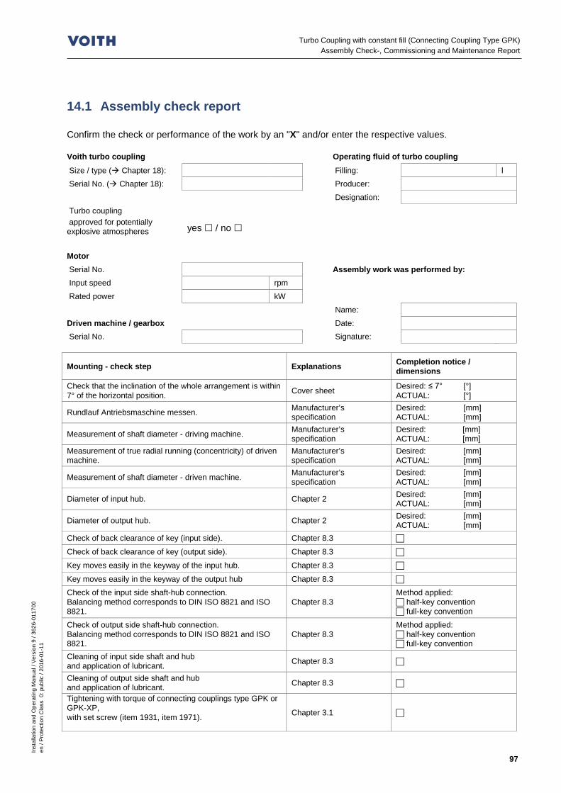
Inst
alla
tion
and
Ope
ratin
g M
anua
l / V
ersi
on 9
/ 36
26-0
1170
0 en
/ Pr
otec
tion
Cla
ss 0
: pub
lic /
2016
-01-
11
97
Turbo Coupling with constant fill (Connecting Coupling Type GPK) Assembly Check-, Commissioning and Maintenance Report
14.1 Assembly check report Confirm the check or performance of the work by an "X" and/or enter the respective values. Voith turbo coupling Operating fluid of turbo coupling Size / type ( Chapter 18): Filling: l Serial No. ( Chapter 18): Producer:
Designation:
Turbo coupling approved for potentially explosive atmospheres yes / no
Motor Serial No. Assembly work was performed by: Input speed rpm Rated power kW
Name: Driven machine / gearbox Date: Serial No. Signature:
Mounting - check step Explanations Completion notice / dimensions
Check that the inclination of the whole arrangement is within 7° of the horizontal position. Cover sheet Desired: ≤ 7° [°]
ACTUAL: [°]
Rundlauf Antriebsmaschine messen. Manufacturer’s specification
Desired: [mm] ACTUAL: [mm]
Measurement of shaft diameter - driving machine. Manufacturer’s specification
Desired: [mm] ACTUAL: [mm]
Measurement of true radial running (concentricity) of driven machine.
Manufacturer’s specification
Desired: [mm] ACTUAL: [mm]
Measurement of shaft diameter - driven machine. Manufacturer’s specification
Desired: [mm] ACTUAL: [mm]
Diameter of input hub. Chapter 2 Desired: [mm] ACTUAL: [mm]
Diameter of output hub. Chapter 2 Desired: [mm] ACTUAL: [mm]
Check of back clearance of key (input side). Chapter 8.3
Check of back clearance of key (output side). Chapter 8.3
Key moves easily in the keyway of the input hub. Chapter 8.3
Key moves easily in the keyway of the output hub Chapter 8.3 Check of the input side shaft-hub connection. Balancing method corresponds to DIN ISO 8821 and ISO 8821.
Chapter 8.3 Method applied: half-key convention full-key convention
Check of output side shaft-hub connection. Balancing method corresponds to DIN ISO 8821 and ISO 8821.
Chapter 8.3 Method applied: half-key convention full-key convention
Cleaning of input side shaft and hub and application of lubricant. Chapter 8.3
Cleaning of output side shaft and hub and application of lubricant. Chapter 8.3
Tightening with torque of connecting couplings type GPK or GPK-XP, with set screw (item 1931, item 1971).
Chapter 3.1

Inst
alla
tion
and
Ope
ratin
g M
anua
l / V
ersi
on 9
/ 36
26-0
1170
0 en
/ Pr
otec
tion
Cla
ss 0
: pub
lic /
2016
-01-
11
98
Turbo Coupling with constant fill (Connecting Coupling Type GPK) Assembly Check-, Commissioning and Maintenance Report
Mounting - check step Explanations Completion notice / dimensions
Measurement of installation dimension “G“. Chapters 8.5.2.1 and 8.6.2.1
Desired: [mm] ACTUAL: [mm]
Measurement of reference dimension "X" (for type GPK only). Chapter 8.5.2.1 Desired: [mm] ACTUAL: [mm]
Check of connecting coupling type GPK or GPK-XP for true radial and axial running.
Chapters 8.5.2.2 and 8.6.2.2
Foundation bolts were tightened. Chapter 8.5.2.3 or 8.6.2.3
Mounting of coupling Tightening of screws (item 1830, item 1955).
Chapters 3.3, 8.5.3 and 8.6.4
Removal of hex. screw (item 1942) and spacer sleeve (item 1943)
Chapter 8.5 and 8.6
For type GPK-KP (with clamping hub) only: Degrease of hub bore and shaft at point ", tightening with torque of the tensioning screws (1946) of the clamping hub
Chapter 8.6.3
Check of reference dimension of distance a / b. Chapters 8.5.4 and 8.6.5
a min. b min. a max. b max. ∆ a ∆ b
MTS / BTS / BTM (if required) Installation position was checked according to operating manual.
Chapter 2 Chapter 19
MTS / BTS / BTM (if required) Electrical functioning was checked.
Chapter 2 Chapter 19
A guard was mounted as recommended. Chapter 11 Equipotential bonding between input and output was realized. Chapter 11 Operating fluid was filled into the coupling. Chapter 10 Number of screws "z" for filling was determined. Chapter 10.1 z = screws
Alignment of turbo coupling was checked. Enter alignment values
Radial running of motor shaft is OK
Entry of displacement values ( Chapters 8.5.2.2 and 8.6.2.2):
Viewing from the motor towards driven machine RADIAL (true radial running) AXIAL (true axial running)
Please tick where applicable - Data from dial gauge - Data from shaft center offset - AXIAL values measured on Ø: . . . . . . . . . .mm
Check of alignment ( Chapters 8.5.4 and 8.6.5) Values within
measuring range Values
a min. yes no ACTUAL: [mm]
a max. yes no ACTUAL: [mm]
b min. yes no ACTUAL: [mm]
b max. yes no ACTUAL: [mm]
∆a yes no ACTUAL: [mm]
∆b yes no ACTUAL: [mm] Displacements during operation (are to be indicated by the machine manufacturer): Observe displacements resulting from an increase in temperature or from mechanical movements. Enter only those values that change the above-ascertained alignment values.
- Radially (e.g. different thermal expansion of input / output) . . . . . . . . . . mm - Axially (e.g. through angular displacements) . . . . . . . . . mm - Längenwachstum (für Einbautoleranz Maß “G“, z. Bsp. Wellenausdehnung . . . . . . . . . . mm

Inst
alla
tion
and
Ope
ratin
g M
anua
l / V
ersi
on 9
/ 36
26-0
1170
0 en
/ Pr
otec
tion
Cla
ss 0
: pub
lic /
2016
-01-
11
99
Turbo Coupling with constant fill (Connecting Coupling Type GPK) Assembly Check-, Commissioning and Maintenance Report
14.2 Commissioning report Confirm the check or performance of the work by an "X" and/or enter the respective values. Voith turbo coupling Commissioning was performed by: Size / type ( Chapter 18): after Oper. hrs.
Serial No. ( Chapter 18): Name:
Turbo coupling Date: approved for potentially explosive atmospheres yes / no Signature:
Commissioning - check step Explanations Completion notice
Checks prior to switching on the drive motor: Assembly/mounting check steps were carried out. Fill in the assembly check report. Chapter 14.1
Removal of hex. screws (item 1942) and spacer sleeves (items 1943)
Chapters 8.5.3 and 8.6.4
Applies only to turbo couplings that are used in potentially explosive atmospheres: Check according to the marking whether the turbo coupling is approved for the use in potentially explosive atmospheres.
Chapter 6.2
Check of filling level / determination of number of screws “z“ for filling Chapter 10.2 / z = screws
Fix a guard over the turbo coupling (for design, Chapter 11). Chapter 11
Check whether the machine was earthed with a grounding cable (16mm²).
Applies only to installations where overspeed is possible: Provide the unit with a device that reliably prevents overspeeds (e.g. brake or backstop).
Chapter 8.1
Determine the next standstill of coupling for maintenance services. Chapter 13
Applies only when a BTS-Ex is used as temperature monitoring system: Make sure that the maximum permissible turbo coupling temperature is not exceeded when switching on the motor!
Chapter 2
Check of disks for deformation, fractures and cracks, as well as for flatness, freedom from distortion, homogeneity of pack.
Chapter 8.4.1, Chapter 13.2
Check of reference dimension of distance a / b. a min. a max. ∆ a
b min. b max. ∆ b
Check of foundation bolts.

Inst
alla
tion
and
Ope
ratin
g M
anua
l / V
ersi
on 9
/ 36
26-0
1170
0 en
/ Pr
otec
tion
Cla
ss 0
: pub
lic /
2016
-01-
11
100
Turbo Coupling with constant fill (Connecting Coupling Type GPK) Assembly Check-, Commissioning and Maintenance Report
Commissioning - check step Explanations Completion notice
Checks during the test run:
Motor run-up is normal.
Turbo coupling is tight. Check of floor and environment for oil moistening, oil did not leak out.
Machine operation is normal.
Noises are normal.
Checks after switching off the drive motor: Turbo coupling is tight. Check of floor and environment for oil moistening, oil did not leak out.
Check of disks for deformation, fractures and cracks, as well as for flatness, freedom from distortion, homogeneity of pack.
Chapter 8.4.1, Chapter 13.2
Check of switch units for temperature monitoring 1), if applicable:
Performance of a visual inspection. 1)
Removal of dust deposits. 1)
Check of electrical system. 1)
1) See separate operating manual / Chapter 19

Inst
alla
tion
and
Ope
ratin
g M
anua
l / V
ersi
on 9
/ 36
26-0
1170
0 en
/ Pr
otec
tion
Cla
ss 0
: pub
lic /
2016
-01-
11
101
Turbo Coupling with constant fill (Connecting Coupling Type GPK) Assembly Check-, Commissioning and Maintenance Report
14.3 Maintenance report for general maintenance Confirm the check or performance of the work by an "X" and/or enter the respective values. Voith turbo coupling The maintenance work was performed by: Size / type ( Chapter 18): after Oper. hrs.
Serial No. ( Chapter 18):
Name:
Turbo coupling Date: approved for potentially explosive atmospheres yes / no Signature:
Maintenance - check step Explanations Completion notice
Check for irregularities (every 500 h, every 3 months at the latest) - Turbo coupling is tight. Check of floor and environment for oil moistening, oil did not leak out.
- Machine operation is normal. - Noises are normal - Check of protective cover. Chapter 11 - Check of foundation bolts.
Check for irregularities (every 12 / 6 / 4 months for 1 / 2 / 3-shift operation) - Check of disks for deformation, fractures and cracks, as well as for flatness, freedom from distortion, homogeneity of pack.
Chapter 8.4.1, Chapter 13.2
- Check of reference dimension of distance a / b. a min. a max. ∆ a
b min. b max. ∆ b
Only for type GPK-XP (with clamping hub): (every 12 / 6 / 4 months for 1 / 2 / 3-shift operation) - Check of tightening torque of tensioning screws (item 1946). Chapter 3.3
Check of switch units for temperature monitoring 1), if applicable (every 3 months) - Performance of a visual inspection. 1) - Removal of dust deposits. 1) - Check of electrical system (after 3 months, then every year).
1)
Operating fluid (every 15000 h) - Check of operating fluid. - Determination of remaining operating time. / hours - Change of operating fluid. Chapter 10
Ball and roller bearings (for the intervals, Chapter 2) - Replacement of ball and roller bearings. Chapter 13.3.3
Cleaning of turbo coupling (after every contamination) - Cleaning was performed. Chapter 13.1
1) See separate operating manual / Chapter 19
Turbo Coupling with constant fill (Connecting Coupling Type GPK) Disassembly of Turbo Coupling
Inst
alla
tion
and
Ope
ratin
g M
anua
l / V
ersi
on 9
/ 36
26-0
1170
0 en
/ Pr
otec
tion
Cla
ss 0
: pub
lic /
2016
-01-
11
102
15 Disassembly of Turbo Coupling WARNING
Risk of injury Please observe, in particular, Chapter 6 (Safety) when working on the turbo coupling! • Before beginning to work on the turbo coupling, switch off the main switch of
the drive motor and secure it against being switched on! • For all work performed on the turbo coupling ensure that both the drive motor
and the driven machine have stopped running and that a re-start is absolutely impossible!
NOTICE
Damage to property Disk pack is damaged due to improper fixing of the turbo coupling. • If one or both hubs are removed, the weight of the turbo coupling needs to be
borne by suitable slings (ropes, chains, etc.).
15.1 Preparation • Prepare suitable tools and lifting appliances.
Observe the turbo coupling weight!
WARNING
Risk of injury Damaged load carrying attachments or those with insufficient carrying capacity may break under load, with the consequence of serious or even fatal injuries! • Check the lifting appliances and load carrying attachments for
- sufficient carrying capacity (for weight, cover sheet), - sound condition.
Weight of turbo coupling Cover sheet Weights of more than 100 kg are stamped on the turbo coupling.

Inst
alla
tion
and
Ope
ratin
g M
anua
l / V
ersi
on 9
/ 36
26-0
1170
0 en
/ Pr
otec
tion
Cla
ss 0
: pub
lic /
2016
-01-
11
103
Turbo Coupling with constant fill (Connecting Coupling Type GPK) Disassembly of Turbo Coupling
WARNING
Risk of injury Falling parts may seriously injure or kill you. • Do not walk under suspended loads.
• Fix the turbo coupling to a suitable lifting appliance. 15.2 Disassembly of type GPK (without clamping hub) For disassembly, proceed according to Chapter 0, in reverse order. Removal devices are not required as the turbo coupling can be installed and removed radially. 15.3 Reassembly of type GPK (without clamping hub) Procedure for reassembly of the turbo coupling is described in Chapter 8.5. 15.4 Disassembly of type GPK-XP (with clamping hub) On account of the constructional features of the clamping hub system, the tensioning screws (item 1946) also serve a puller spindles. Apply the respective torque to the initial loosening. Then turn back all screws until there is a resistance. Following that, apply increasing torque to the screws, one after the other, as described in Chapter 8.6.4, until the clamping ring looses. 15.5 Reassembly of type GPK-XP (with clamping hub) Procedure for reassembly of the clamping hub is described in Chapter 8.6. If a lack of lubricant is found on one of the surfaces marked with (V), relubrication with grease (for grease type Chapter 8.3) becomes necessary.
SAFETY INFORMATION
Make sure that the joint surfaces (W) on the shaft and hub bore are clean (free from grease). If there is a grease film on the joint surfaces, there is the risk of slipping with the consequence of friction heat.
Lifting appliances Chapter 7.4
Surface/point V Chapter 8.6.3

Turbo Coupling with constant fill (Connecting Coupling Type GPK) Disposal
Inst
alla
tion
and
Ope
ratin
g M
anua
l / V
ersi
on 9
/ 36
26-0
1170
0 en
/ Pr
otec
tion
Cla
ss 0
: pub
lic /
2016
-01-
11
104
16 Disposal Disposal of the packaging Dispose of packaging material according to the local regulations. How to dispose of operating fluids On disposal, please observe the applicable laws and the producer's or supplier's instructions. How to dispose of the turbo coupling Clean the turbo coupling carefully to ensure a purity of material. Dismantle the turbo coupling, if necessary. Dispose of the turbo coupling according to the local regulations. For special information on the disposal of the substances and materials used, please see the following table:
Kind of disposal
Material / substance Reuse Residual waste Special waste
Metals x - -
Cables x - -
Seals - x -
Plastics x 1) (x) -
Operating media - - x 1), 2)
Packaging x - -
Table 27
1) If possible 2) Disposal according to the safety data sheet or the manufacturer's instructions

Inst
alla
tion
and
Ope
ratin
g M
anua
l / V
ersi
on 9
/ 36
26-0
1170
0 en
/ Pr
otec
tion
Cla
ss 0
: pub
lic /
2016
-01-
11
105
Turbo Coupling with constant fill (Connecting Coupling Type GPK) Malfunctions - Remedial Actions
17 Malfunctions - Remedial Actions WARNING
Risk of injury Please observe, in particular, Chapter 6 (Safety) when working on the turbo coupling!
The following table is intended to help finding the cause of malfunctions or problems quickly and to take remedial action, if necessary.
Malfunction Possible cause(s)
Remedial action See
Starting behavior of driven machine is not as expected.
Turbo coupling is not filled with the correct quantity of operating fluid.
Check and correct the quantity filled in.
Chapter 10.1
The operating conditions have changed.
Please consult Voith Turbo. Chapter 18
Driven machine does not reach the specified speed.
Driven machine is blocked or overloaded.
Eliminate blocking or the cause of overload.
Turbo coupling is not filled with the correct quantity of operating fluid.
Check and correct the quantity filled in.
Chapter 10.1
Drive motor does not reach normal operation within the expected time.
Changeover from star to delta too late.
Changeover from star to delta should be made after 2...5s at the latest.
Drive motor is electrically or mechanically not in order.
Have the drive motor checked by authorized personnel.
Operating fluid leaks out of the turbo coupling.
A fusible plug responded due to overload (excess temperature).
Clarify the cause for the overload. Replace all fusible plugs and change the operating fluid.
Chapter 13.4

Turbo Coupling with constant fill (Connecting Coupling Type GPK) Malfunctions - Remedial Actions
Inst
alla
tion
and
Ope
ratin
g M
anua
l / V
ersi
on 9
/ 36
26-0
1170
0 en
/ Pr
otec
tion
Cla
ss 0
: pub
lic /
2016
-01-
11
106
Malfunction Possible cause(s)
Remedial action See
Operating fluid leaks out of the turbo coupling.
The turbo coupling is leaky.
Eliminate the leak, check, in particular, tightening torques and seal rings of fusible and filler plugs as well as sight glasses and, if necessary, check the switching element of the thermal switch unit. If the leak cannot be eliminated, please consult Voith Turbo.
Chapter 3 Chapter 18
An existing thermal monitoring unit (MTS, BTS or BTM) has responded.
The turbo coupling was overloaded.
Clarify the cause for the overload, and avoid another overload. Check and correct the quantity filled in.
Chapter 19 Chapter 10.2
Thermal monitoring unit (MTS, BTS or BTM) is defective.
Check the monitoring unit. Chapter 19
Uneven running of the machine (increased vibration).
Foundation fixing is loose.
Retighten the foundation fixing. Align the machine.
The machine is not aligned.
Align the machine. Chapter 8.5.2 and 8.6.2
Machine is not balanced.
Clarify the cause and eliminate the unbalance.
The disk packs of the connecting coupling are defective.
Replace the disk packs, consult Voith Turbo.
Chapter 13.2 Chapter 18
Bearings are damaged.
Eliminate the bearing damage; consult Voith Turbo in case of a bearing damage on the turbo coupling.
Chapter 18
Loose screw connections.
Check the coupling components for damages, and replace the same, if necessary. Check the alignment of the machine. Tighten the screws and bolts with the specified tightening torque.
Chapter 3
Please consult Voith Turbo ( Chapter 18), in case of a malfunction which is not included in this table.
Table 28

Inst
alla
tion
and
Ope
ratin
g M
anua
l / V
ersi
on 9
/ 36
26-0
1170
0 en
/ Pr
otec
tion
Cla
ss 0
: pub
lic /
2016
-01-
11
107
Turbo Coupling with constant fill (Connecting Coupling Type GPK) Queries, Orders Placed for Service Engineers and Spare Parts
18 Queries, Orders Placed for Service Engineers and Spare Parts
For – Queries – Ordering a service engineer – Spare parts orders – Commissionings we need:
Fig. 44
the serial number and type designation of the turbo coupling. You will find the serial number and
type designation either on the outer wheel / coupling shell (A) or on the turbo coupling periphery (B).
The serial number is stamped in with figure stamps.
For turbo couplings, intended for the use in potentially explosive atmospheres, you will find the CE-Ex marking on the turbo coupling periphery.
When placing an order for a service engineer, commissioning or a service, we need, in addition – the turbo coupling installation site, – the name and address of a contact person, – details of the malfunction/problem occurred. When placing a spare parts order, we need, in addition, – the destination for the spare parts shipment. Please contact the local Voith representative (outside business hours: the emergency hotline).
Representatives Chapter 21
Type designation CE-Ex marking
Serial No. A B

Turbo Coupling with constant fill (Connecting Coupling Type GPK) Temperature monitoring
Inst
alla
tion
and
Ope
ratin
g M
anua
l / V
ersi
on 9
/ 36
26-0
1170
0 en
/ Pr
otec
tion
Cla
ss 0
: pub
lic /
2016
-01-
11
108
19 Temperature monitoring SAFETY INFORMATION
The thermal switch units MTS and BTS can be used in potentially explosive atmospheres to monitor the temperature. The signals serve for pre-warning. The MTS or BTS do not limit the maximum surface temperature. The BTS-Ex is available as safety device to limit the maximum surface tem-perature, and it can be used as thermal switch-off device. Also in this case, it is not allowed to replace the existing fusible plugs by fusible plugs with different nominal response temperatures or by blind screws. Never bypass safety devices!
DANGER
Electric shock Electric voltage may kill or severely injure you • A qualified electrician has to properly carry out the connection to the electric
supply network considering the system voltage and the maximum power con-sumption!
• The system voltage has to be in conformity with the system voltage indicated on the nameplate!
• There has to be a corresponding electrical protection by a fuse on the network side.
The temperature in the turbo coupling can be monitored by means of a limit switch or a temperature instrument. The following systems are available as limit switch: – a mechanical MTS system – an electronic BTS system . These limit switches serve to monitor the temporarily permissible peak temperature, and to prevent a response of the fusible plugs provided the overload is eliminated promptly (e.g. by switching off the drive). The BTM can be used as temperature measuring device. This way, not only the temporarily permissible peak temperature can be monitored, but also the nominal operation.
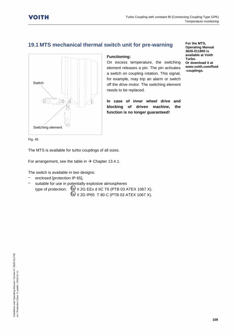
Inst
alla
tion
and
Ope
ratin
g M
anua
l / V
ersi
on 9
/ 36
26-0
1170
0 en
/ Pr
otec
tion
Cla
ss 0
: pub
lic /
2016
-01-
11
109
Turbo Coupling with constant fill (Connecting Coupling Type GPK) Temperature monitoring
19.1 MTS mechanical thermal switch unit for pre-warning
Fig. 45
Functioning: On excess temperature, the switching element releases a pin. The pin activates a switch on coupling rotation. This signal, for example, may trip an alarm or switch off the drive motor. The switching element needs to be replaced. In case of inner wheel drive and blocking of driven machine, the function is no longer guaranteed!
The MTS is available for turbo couplings of all sizes. For arrangement, see the table in Chapter 13.4.1. The switch is available in two designs: – enclosed [protection IP 65], – suitable for use in potentially explosive atmospheres
type of protection: II 2G EEx d IIC T6 (PTB 03 ATEX 1067 X). II 2D IP65 T 80 C (PTB 03 ATEX 1067 X).
For the MTS, Operating Manual 3626-011800 is available at Voith Turbo. Or download it at www.voith.com/fluid-couplings.
Switch
Switching element

Turbo Coupling with constant fill (Connecting Coupling Type GPK) Temperature monitoring
Inst
alla
tion
and
Ope
ratin
g M
anua
l / V
ersi
on 9
/ 36
26-0
1170
0 en
/ Pr
otec
tion
Cla
ss 0
: pub
lic /
2016
-01-
11
110
19.2 BTS non-contacting thermal switch unit 19.2.1 BTS non-contacting thermal switch unit for pre-
warning
Fig. 46
Functioning: On excess temperature, the switching element gives a specific signal to the initiator. This signal is transferred to an evaluator and may, for example, – trigger an alarm – or switch off the drive motor. After the turbo coupling has cooled down, the switching element is again ready for service; it does not have to be replaced.
The BTS is provided for turbo couplings of all sizes. For arrangement, see the table in Chapter 13.4.1. Switching element and initiator are – cast in plastic, – insensitive to dirt, – suitable for use in potentially explosive atmospheres
type of protection: II 2G EEx ia IIC T6 (PTB 00 ATEX 2048 X). II 1D Ex iaD 20 T... C (ZELM 03 ATEX 0128 X).
SAFETY INFORMATION
As the control circuit of the evaluator is not intrinsically safe, provide an appro-priate isolating switch amplifier between evaluator and initiator!
– Isolating switch amplifier type KFD2-SOT2-Ex2 (24 V DC)
type of protection: II (1) GD [EEx ia] IIC (PTB 00 ATEX 2035).
– Isolating switch amplifier type KFA6-SOT2-Ex2 (230 V AC) type of protection: II (1) G [EEx ia] IIC (PTB 98 ATEX 2164).
For the BTS, Operating Manual 3626-011500 is available at Voith Turbo. Or download it at www.voith.com/fluid-couplings
Initiator
Switching element

Inst
alla
tion
and
Ope
ratin
g M
anua
l / V
ersi
on 9
/ 36
26-0
1170
0 en
/ Pr
otec
tion
Cla
ss 0
: pub
lic /
2016
-01-
11
111
Turbo Coupling with constant fill (Connecting Coupling Type GPK) Temperature monitoring
19.2.2 BTS-Ex non-contacting thermal switch unit for limiting the maximum surface temperature
Fig. 47
Functioning: On excess temperature, the switching element gives a specific signal to the initiator. This signal is sent to an isolating switch amplifier and has to enforce the switch-off of the drive motor. Use a BTS-Ex approved by Voith for this application. After the turbo coupling has cooled down, the switching element is again ready for service; it does not have to be replaced.
The BTS-Ex is provided for turbo couplings of all sizes. For arrangement, see the table in Chapter 13.4.2. The BTS-Ex is provided for use in potentially explosive atmospheres as per ATEX Directive in Equipment Group II, Equipment Category 2G and 2D ( II 2GD).
SAFETY INFORMATION
The BTS-Ex for limiting the maximum surface temperature is approved only in connection with the components supplied by Voith according to BTS-Ex operating manual. Use of original Voith spare parts is imperative in case of a replacement demand. The evaluator serves to transmit control commands from potentially explosive atmospheres into non-explosive areas and to safely isolate intrinsically safe and non-intrinsically safe circuits. • Make sure not to exceed the maximum permissible temperature of the turbo
coupling when switching on the motor.
For the BTS-Ex, Operating Manual 3626-019600 is available at Voith Turbo. Or download it at www.voith.com/fluid-couplings
Technical data Chapter 2
Initiator
Switching element

Turbo Coupling with constant fill (Connecting Coupling Type GPK) Temperature monitoring
Inst
alla
tion
and
Ope
ratin
g M
anua
l / V
ersi
on 9
/ 36
26-0
1170
0 en
/ Pr
otec
tion
Cla
ss 0
: pub
lic /
2016
-01-
11
112
19.3 BTM non-contacting thermal measuring device for pre-warning
Fig. 48
Functioning: The temperature sensor permanently transmits a measuring signal to the an-tenna. This signal is sent to an evaluator with 4 channels. The measured temperatures of every channel are indicated on the evaluator. In addition, the measured temperatu-res are output as 4-20 mA signals. Furthermore, two relay outputs are available per measuring channel with switching thresholds (e.g. pre-warning, switch-off) adjustable via the keyboard on the evaluator.
The BTM is provided for turbo couplings of all sizes. For arrangement, see the table in Chapter 13.4.1.
SAFETY INFORMATION
The BTM is not provided for use in potentially explosive areas as per ATEX Directive.
For the BTM, Operating Manual 3626-019800 is available at Voith Turbo. Or download it at www.voith.com/fluid-couplings
Antenna Temperature sensor
BTM blind screw
Inst
alla
tion
and
Ope
ratin
g M
anua
l / V
ersi
on 9
/ 36
26-0
1170
0 en
/ Pr
otec
tion
Cla
ss 0
: pub
lic /
2016
-01-
11
113
Turbo Coupling with constant fill (Connecting Coupling Type GPK) Spare parts information
20 Spare parts information SAFETY INFORMATION
Variety of variants Considering the great variety, please find in the following only the basic design of turbo couplings with constant fill (connecting coupling type GPK).
– Spare parts must comply with the technical requirements determined by Voith.
This is guaranteed when original spare parts are used. Installation and/or use of non-original spare parts may negatively change the mechanical properties of the Voith turbo couplings, and may thus impair safety. Voith is not liable for any damages resulting from the use of non-original spare parts.
– You will find the type of your turbo coupling on the cover sheet of this operating manual.
– Observe Chapter 1.2 (type designation) and Chapter 18 (Queries, Orders places for Service Engineers and Spare Parts).
– The customer is only allowed to perform the following work: - Replacement of fusible pluts (item 0395 / 0260) ( Chapter 13.4). - Work according to maintenance report ( Chapter 14.3). - Change of operating fluid ( Chapter 10). - Mounting of parts for which tightening torques are indicated ( Chapter 3). All remaining work may be performed by Voith staff only.
NOTICE
Unauthorized changes or retrofits are not allowed to be performed on the coupling! Do not retrofit accessories or equipment originating from other manufacturers! Any changes or conversions performed without the prior written consent of Voith Turbo will result in the loss of any warranty! Any claims will forfeit! • Professional maintenance or repair can only be guaranteed by the
manufacturer!
SAFETY INFORMATION
If the turbo coupling is used in potentially explosive atmospheres (as per ATEX Directive), the use of original parts that have been released for use in hazardous areas is allowed only.

Turbo Coupling with constant fill (Connecting Coupling Type GPK) Spare parts information
Inst
alla
tion
and
Ope
ratin
g M
anua
l / V
ersi
on 9
/ 36
26-0
1170
0 en
/ Pr
otec
tion
Cla
ss 0
: pub
lic /
2016
-01-
11
114
20.1 Components overview - Voith turbo coupling 366 – 1150
Fig. 49
Item No. Description Item No. Description
0040 Coupling hub 0190 Coupling shell
0050 Fixing bolt 0210 Tolerance ring
0080 Holding disk 0300 Outer wheel
0090 Inner wheel 0320 Tolerance ring
0100 Riveting ring/threaded ring/clamping ring
0410 Delay chamber cover
0130 Grooved ball bearing 0800 Bearing support cover
0140 Grooved ball bearing 0830 Sealing ring cover
0160 Radial shaft sealing ring 0990 Connecting cover
0170 Radial shaft sealing ring
Table 29 Spare parts for Voith turbo copupling, Chapter 20.2.
0190
0300
0800
0170
0130
0990
0040/0090/0100
0190
0080
0050
0830
0210
0140
0160
0410
0320

Inst
alla
tion
and
Ope
ratin
g M
anua
l / V
ersi
on 9
/ 36
26-0
1170
0 en
/ Pr
otec
tion
Cla
ss 0
: pub
lic /
2016
-01-
11
115
Turbo Coupling with constant fill (Connecting Coupling Type GPK) Spare parts information
20.2 Spare parts for Voith turbo coupling 366 – 1150
Fig. 50
1) For arrangement and quantity, see the tables Chapter 13.4 2) Only for continuous operation or operating fluid 'water' (TW…). 3) For sizes 366 and 422 inserted in the delay chamber groove.
xxxx Nonrepairable items ( the following table) xxxx Repair parts / wearing parts (V) ( the following table)
0260/0265/0270 1)
The example shows turbo coupling type TVV
0320
0165 2)
0140
0160
0210
0175 2)
0994
0545
0394/0395/0396/0405 1)
0170
0510 3)
0820
0130
0455/0465
0390/0400
0050
0070
0080
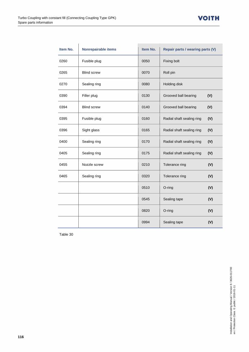
Turbo Coupling with constant fill (Connecting Coupling Type GPK) Spare parts information
Inst
alla
tion
and
Ope
ratin
g M
anua
l / V
ersi
on 9
/ 36
26-0
1170
0 en
/ Pr
otec
tion
Cla
ss 0
: pub
lic /
2016
-01-
11
116
Item No. Nonrepairable items Item No. Repair parts / wearing parts (V)
0260 Fusible plug 0050 Fixing bolt
0265 Blind screw 0070 Roll pin
0270 Sealing ring 0080 Holding disk
0390 Filler plug 0130 Grooved ball bearing (V)
0394 Blind screw 0140 Grooved ball bearing (V)
0395 Fusible plug 0160 Radial shaft sealing ring (V)
0396 Sight glass 0165 Radial shaft sealing ring (V)
0400 Sealing ring 0170 Radial shaft sealing ring (V)
0405 Sealing ring 0175 Radial shaft sealing ring (V)
0455 Nozzle screw 0210 Tolerance ring (V)
0465 Sealing ring 0320 Tolerance ring (V)
0510 O-ring (V)
0545 Sealing tape (V)
0820 O-ring (V)
0994 Sealing tape (V)
Table 30

Inst
alla
tion
and
Ope
ratin
g M
anua
l / V
ersi
on 9
/ 36
26-0
1170
0 en
/ Pr
otec
tion
Cla
ss 0
: pub
lic /
2016
-01-
11
117
Turbo Coupling with constant fill (Connecting Coupling Type GPK) Spare parts information
20.3 Spare parts for connecting coupling type GPK (without clamping hub)
Fig. 51
Item No. Screws and standard parts Item No. Connecting coupling parts
0050 Fixing bolt 0080 Holding disk
0070 Roll pin 1932 Input, assembly
1830 Hex. screw 1950 GPK stub shaft
1931 Set screw 1972 Output, assembly
1951 Key
1955 Set of screws
1971 Set screw
Table 31
Item No. Transport protector
1942 Hex. screw for transport protector
1943 Spacer sleeve for transport protector
Table 32
Transport protector Chapter 8.5, Chapter 8.5.3
1951
1971
1972
1950
1955
0070
0050
1932
1830
0080
1931
Transport protector not illustrated.

Turbo Coupling with constant fill (Connecting Coupling Type GPK) Spare parts information
Inst
alla
tion
and
Ope
ratin
g M
anua
l / V
ersi
on 9
/ 36
26-0
1170
0 en
/ Pr
otec
tion
Cla
ss 0
: pub
lic /
2016
-01-
11
118
20.4 Spare parts for connecting coupling type GPK-XP (with clamping hub)
Fig. 52
Item No. Screws and standard parts Item No. Connecting coupling parts
0050 Fixing bolt 0080 Holding disk
0070 Roll pin 1932 Input, assembly
1830 Hex. screw 1945 Clamping hub
1931 Set screw 1950 GPK stub shaft
1951 Key 1972 Output, assembly
1955 Set of screws
1971 Set screw
Table 33
Item No. Transport protector
1942 Hex. screw for transport protector
1943 Spacer sleeve for transport protector
Table 34
Transport protector Chapter 8.6, Chapter 8.6.4
1972
1955
1945
1950
1971
1830
0080
1931
0050 0070
1932
Transport protector not illustrated.
1951

Inst
alla
tion
and
Ope
ratin
g M
anua
l / V
ersi
on 9
/ 36
26-0
1170
0 en
/ Pr
otec
tion
Cla
ss 0
: pub
lic /
2016
-01-
11
119
Turbo Coupling with constant fill (Connecting Coupling Type GPK) Representatives - Voith Turbo GmbH & Co. KG
21 Representatives - Voith Turbo GmbH & Co. KG
Westeuropa: Deutschland ( VTCR ): Voith Turbo GmbH & Co. KG Division Mining & Metals Voithstr. 1 74564 CRAILSHEIM GERMANY Tel.: +49-7951 32-409 Fax: +49-7951 32-480 e-mail: [email protected] www.voith.com/fluid-couplings
Service: Tel.: +49 7951 32-1020 Fax: +49 7951 32-554 e-mail: [email protected]
Notfall Hotline (24/7): Tel.: +49 7951 32-599 Belgien ( VTBV ): Voith Turbo S. A. / N. V. Square Louisa 36 1150 BRÜSSEL BELGIUM Tel.: +32-2-7626100 Fax: +32-2-7626159 e-mail: [email protected] Dänemark ( VTDK ): Voith Turbo A/S Egegårdsvej 5 4621 GADSTRUP DENMARK Tel.: +45-46 141550 Fax: +45-46 141551 e-mail: [email protected] Färöer Inseln: siehe Dänemark ( VTDK ) Finnland ( Masino ): Masino Oy Kärkikuja 3 01740 VANTAA FINLAND Tel.: +358-10-8345 500 Fax: +358-10-8345 501 e-mail: [email protected]
Frankreich ( VTFV ): Voith Turbo S. A. S. 21 Boulevard du Champy-Richardets 93166 NOISY-LE-GRAND CEDEX FRANCE Tel.: +33-1-4815 6903 Fax: +33-1-4815 6901 e-mail: [email protected] Griechenland: siehe Deutschland (VTCR) Grönland: siehe Dänemark ( VTDK ) Großbritannien ( VTGB ): Voith Turbo Limited 6, Beddington Farm Road CRO 4XB CROYDON, SURREY GREAT BRITAIN Tel.: +44-20-8667 0333 Fax: +44-20-8667 0403 e-mail: [email protected]
Notfall Hotline (24/7): Tel.: +44-20-8667 0333 Irland: siehe Großbritannien ( VTGB ) Italien ( VTIV ): Voith Turbo s.r.l. Via G. Lambrakis 2 42122 REGGIO EMILIA ITALY Tel.: +39-05-2235-6714 Fax: +39-05-2235-6790 e-mail: [email protected] Liechtenstein: siehe Deutschland ( VTCR ) Luxemburg: siehe Belgien ( VTBV )
Niederlande ( VTNT ): Voith Turbo B.V. Koppelstraat 3 7391 AK TWELLO THE NETHERLANDS Tel.: +31-571-2796-00 Fax: +31-571-2764-45 e-mail: [email protected] Norwegen ( VTNO ): Voith Turbo AS Lahaugmoveien 30A 2013 SKJETTEN NORWAY Tel.: +47 6384 7020 Fax: +47 6384 7021 e-mail: [email protected] Österreich: Indukont Antriebstechnik GmbH Badenerstraße 40 2514 TRAISKIRCHEN AUSTRIA Tel.: +43-2252-81118-22 Fax: +43-2252-81118-99 e-mail: [email protected] Portugal: siehe Spanien ( VTEV ) Schweden ( VTSN ): Voith Turbo AB Finspångsgatan 46 16353 SPÅNGA-STOCKHOLM SWEDEN Tel.: +46-8-564-755-50 Fax: +46-8-564-755-60 e-mail: [email protected] Schweiz: siehe Deutschland ( VTCR ) Spanien ( VTEV ): Voith Turbo S. A. Avenida de Suiza 3 P.A.L. Coslada 28820 COSLADA (MADRID) SPAIN Tel.: +34-91-6707816 Fax: +34-91-6707841 e-mail: [email protected]

Turbo Coupling with constant fill (Connecting Coupling Type GPK) Representatives - Voith Turbo GmbH & Co. KG
Inst
alla
tion
and
Ope
ratin
g M
anua
l / V
ersi
on 9
/ 36
26-0
1170
0 en
/ Pr
otec
tion
Cla
ss 0
: pub
lic /
2016
-01-
11
120
Osteuropa: Albanien: siehe Ungarn ( VTHU ) Bosnien-Herzegowina: siehe Ungarn ( VTHU ) Bulgarien: siehe Ungarn ( VTHU ) Estland: siehe Polen ( VTPL ) Kosovo: siehe Ungarn ( VTHU ) Kroatien: siehe Ungarn ( VTHU ) Lettland: siehe Polen ( VTPL ) Litauen: siehe Polen ( VTPL ) Mazedonien: siehe Ungarn ( VTHU ) Polen ( VTPL ): Voith Turbo sp.z o.o. Majków Duży 74 97-371 WOLA KRZYSZTOPORSKA POLAND Tel.: +48-44 646 8848 Fax: +48-44-646 8520 e-mail: [email protected]
Notfall Hotline (24/7): Tel.: +48-44 646 8519 Rumänien ( VTRO ): Voith Turbo S.R.L. Strada Barbu Vacarescu nr. 13 etaj 3 si 4 020271 BUCHAREST ROMANIA Tel.: +40-31-22 36100 Fax: +40-31-22 36210 e-mail: [email protected]
Russland ( VTRU ): Voith Turbo O.O.O. Branch Office Moskau Nikolo Yamskaya ul. 21/7, str. 3 109240 MOSKAU RUSSIA Tel.: +7 495 915-3296 ext. 122 Fax: +7 495 915-3816 Mobil Herr Bulanzev: +7 919 108 2468 e-mail: [email protected] Voith Turbo Branch Office Novokusnetsk ( Shcherbinin, Anatoliy ) Skorosnaya ul. 41, Liter B1 654025 NOVOKUSNETSK Kemerovskaya oblast RUSSIA Tel./Fax: +7 3843 311 109 Mobil: +7 9132 802 110 e-mail: [email protected] Serbien: siehe Ungarn ( VTHU ) Slowakische Rep.: siehe Tschechien ( VTCZ ) Slowenien: siehe Ungarn ( VTHU ) Tschechien ( VTCZ ): Voith Turbo s.r.o. Hviezdoslavova 1a 62700 BRNO CZECH REPUBLIC Tel.: +420-543-176163 Fax: +420-548-226051 e-mail: [email protected] Ukraine ( VTUA ): Voith Turbo Ltd. Degtyarivska Str. 25, Building 1 04119 KIEV UKRAINE Tel.: +380-44-581 4760 Fax: +380-44-581 4761 e-mail: [email protected] siehe auch Polen ( VTPL ) Ungarn ( VTHU ): Voith Turbo Kft. Felvég Útca 4 2051 BIATORBÁGY HUNGARY Tel.: +36-23-312 431 Fax: +36-23-310 441 e-mail: [email protected]
Nordamerika: Kanada ( VTC ): Voith Turbo Inc. 171 Ambassador Drive, Unit 1 L5T 2J1 MISSISSAUGA, ONTARIO CANADA Tel.: +1-905-670-3122 Fax: +1-905-670-8067 e-mail: [email protected]
Notfall Hotline (24/7): Tel.: +1-905-738-1829 Mexico ( VTX ): Voith Turbo S.A. de C.V. Alabama No.34 Col. Nápoles Delg. Benito Juarez C.P. 03810 MÉXICO, D.F. MÉXICO Tel.: +52-55-5340 6970 Fax: +52-55-5543 2885 e-mail: [email protected] USA ( VTI ): Voith Turbo Inc. 25 Winship Road YORK, PA 17406-8419 UNITED STATES Tel.: +1-717-767 3200 Fax: +1-717-767 3210 e-mail: [email protected]
Notfall Hotline (24/7): Tel.: +1-717-767 3200 e-mail: [email protected]

Inst
alla
tion
and
Ope
ratin
g M
anua
l / V
ersi
on 9
/ 36
26-0
1170
0 en
/ Pr
otec
tion
Cla
ss 0
: pub
lic /
2016
-01-
11
121
Turbo Coupling with constant fill (Connecting Coupling Type GPK) Representatives - Voith Turbo GmbH & Co. KG
Süd- + Mittelamerika: Brasilien ( VTPA ): Voith Turbo Ltda. Rua Friedrich von Voith 825 02995-000 JARAGUÁ, SÃO PAULO - SP BRAZIL Tel.: +55-11-3944 4393 Fax: +55-11-3941 1447 e-mail: [email protected]
Notfall Hotline (24/7): Tel.: +55-11-3944 4646 Chile ( VTCI ): Voith Turbo S. A. Av. Pdte.Eduardo Frei Montalva 6115 8550189 SANTIAGO DE CHILE (CONCHALI) CHILE Tel.: +56-2-944-6900 Fax: +56-2-944-6950 e-mail: [email protected] Ecuador: siehe Kolumbien ( VTKB ) Kolumbien ( VTKB ): Voith Turbo Colombia Ltda. Calle 17 No. 69-26 Centro Empresarial Montevideo 110931 BOGOTÁ, D.C. COLOMBIA Tel.: +57 141-17664 Fax: +57 141-20590 e-mail: [email protected] Peru ( VTPE ): Voith Turbo S.A.C. Av. Argentina 2415 LIMA 1 PERU Tel.: +51-1-6523014 e-mail: [email protected] siehe auch Brasilien ( VTPA ) Venezuela: siehe Kolumbien ( VTKB )
Afrika: Ägypten: Copam Egypt 33 El Hegaz Street, W. Heliopolis 11771 CAIRO EGYPT Tel.: +202-22566 299 Fax: +202-22594 757 e-mail: [email protected] Algerien: siehe Frankreich ( VTFV ) Botswana: siehe Südafrika ( VTZA ) Elfenbeinküste: siehe Frankreich ( VTFV ) Gabun: siehe Frankreich ( VTFV ) Guinea: siehe Frankreich ( VTFV ) Lesotho: siehe Südafrika ( VTZA ) Marokko ( VTCA ): Voith Turbo S.A. Rue Ibnou El Koutia, No. 30 Lot Attawfiq - Quartier Oukacha 20250 CASABLANCA MOROCCO Tel:. +212 522 34 04 41 Fax. +212 522 34 04 45 e-mail: [email protected] Mauretanien: siehe Spanien ( VTEV ) Mozambique: siehe Südafrika ( VTZA ) Namibia: siehe Südafrika ( VTZA ) Niger: siehe Frankreich ( VTFV ) Senegal: siehe Frankreich ( VTFV )
Südafrika ( VTZA ): Voith Turbo Pty. Ltd. 16 Saligna Street Hughes Business Park 1459 WITFIELD, BOKSBURG SOUTH AFRICA Tel.: +27-11-418-4000 Fax: +27-11-418-4080 e-mail: [email protected]
Notfall Hotline (24/7): Tel.: +27-11-418-4060 Swaziland: siehe Südafrika ( VTZA ) Tunesien: siehe Frankreich ( VTFV ) Zambia: siehe Südafrika ( VTZA ) Zimbabwe: siehe Südafrika ( VTZA )
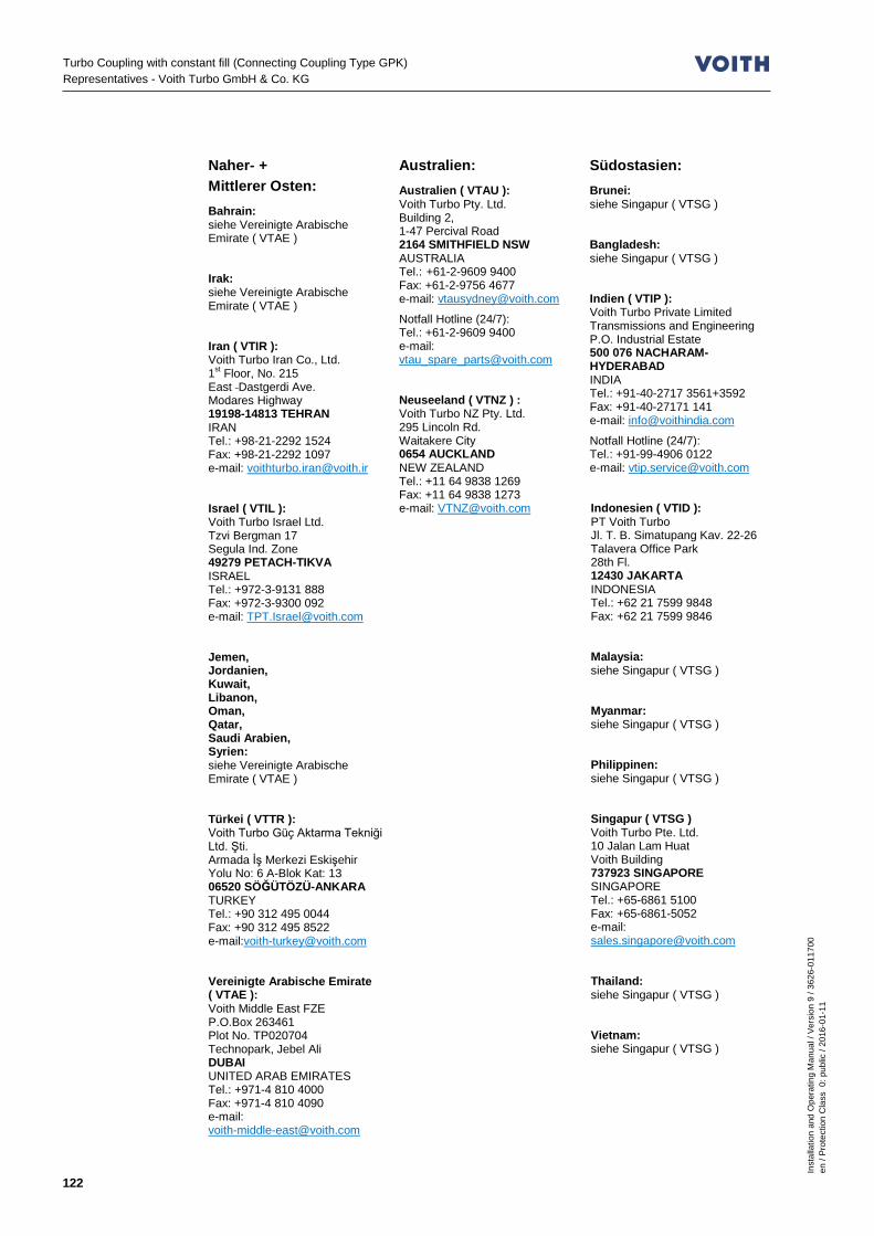
Turbo Coupling with constant fill (Connecting Coupling Type GPK) Representatives - Voith Turbo GmbH & Co. KG
Inst
alla
tion
and
Ope
ratin
g M
anua
l / V
ersi
on 9
/ 36
26-0
1170
0 en
/ Pr
otec
tion
Cla
ss 0
: pub
lic /
2016
-01-
11
122
Naher- + Mittlerer Osten: Bahrain: siehe Vereinigte Arabische Emirate ( VTAE ) Irak: siehe Vereinigte Arabische Emirate ( VTAE ) Iran ( VTIR ): Voith Turbo Iran Co., Ltd. 1st Floor, No. 215 East Dastgerdi Ave. Modares Highway 19198-14813 TEHRAN IRAN Tel.: +98-21-2292 1524 Fax: +98-21-2292 1097 e-mail: [email protected] Israel ( VTIL ): Voith Turbo Israel Ltd. Tzvi Bergman 17 Segula Ind. Zone 49279 PETACH-TIKVA ISRAEL Tel.: +972-3-9131 888 Fax: +972-3-9300 092 e-mail: [email protected] Jemen, Jordanien, Kuwait, Libanon, Oman, Qatar, Saudi Arabien, Syrien: siehe Vereinigte Arabische Emirate ( VTAE ) Türkei ( VTTR ): Voith Turbo Güç Aktarma Tekniği Ltd. Şti. Armada İş Merkezi Eskişehir Yolu No: 6 A-Blok Kat: 13 06520 SÖĞÜTÖZÜ-ANKARA TURKEY Tel.: +90 312 495 0044 Fax: +90 312 495 8522 e-mail:[email protected] Vereinigte Arabische Emirate ( VTAE ): Voith Middle East FZE P.O.Box 263461 Plot No. TP020704 Technopark, Jebel Ali DUBAI UNITED ARAB EMIRATES Tel.: +971-4 810 4000 Fax: +971-4 810 4090 e-mail: [email protected]
Australien: Australien ( VTAU ): Voith Turbo Pty. Ltd. Building 2, 1-47 Percival Road 2164 SMITHFIELD NSW AUSTRALIA Tel.: +61-2-9609 9400 Fax: +61-2-9756 4677 e-mail: [email protected]
Notfall Hotline (24/7): Tel.: +61-2-9609 9400 e-mail: [email protected] Neuseeland ( VTNZ ) : Voith Turbo NZ Pty. Ltd. 295 Lincoln Rd. Waitakere City 0654 AUCKLAND NEW ZEALAND Tel.: +11 64 9838 1269 Fax: +11 64 9838 1273 e-mail: [email protected]
Südostasien: Brunei: siehe Singapur ( VTSG ) Bangladesh: siehe Singapur ( VTSG ) Indien ( VTIP ): Voith Turbo Private Limited Transmissions and Engineering P.O. Industrial Estate 500 076 NACHARAM-HYDERABAD INDIA Tel.: +91-40-2717 3561+3592 Fax: +91-40-27171 141 e-mail: [email protected]
Notfall Hotline (24/7): Tel.: +91-99-4906 0122 e-mail: [email protected] Indonesien ( VTID ): PT Voith Turbo Jl. T. B. Simatupang Kav. 22-26 Talavera Office Park 28th Fl. 12430 JAKARTA INDONESIA Tel.: +62 21 7599 9848 Fax: +62 21 7599 9846 Malaysia: siehe Singapur ( VTSG ) Myanmar: siehe Singapur ( VTSG ) Philippinen: siehe Singapur ( VTSG ) Singapur ( VTSG ) Voith Turbo Pte. Ltd. 10 Jalan Lam Huat Voith Building 737923 SINGAPORE SINGAPORE Tel.: +65-6861 5100 Fax: +65-6861-5052 e-mail: [email protected] Thailand: siehe Singapur ( VTSG ) Vietnam: siehe Singapur ( VTSG )

Inst
alla
tion
and
Ope
ratin
g M
anua
l / V
ersi
on 9
/ 36
26-0
1170
0 en
/ Pr
otec
tion
Cla
ss 0
: pub
lic /
2016
-01-
11
123
Turbo Coupling with constant fill (Connecting Coupling Type GPK) Representatives - Voith Turbo GmbH & Co. KG
Ostasien: China: siehe Hongkong ( VTEA ) Voith Turbo Power Transmission (Shanghai) Co., Ltd. ( VTCB ) Beijing Branch 18 Floor, Tower F, Phoenix Place 5A Shuguang Xili, Chaoyang District 100028 BEIJING P.R. CHINA Tel.: +86-10-5665 3388 Fax: +86-10-5665 3333 e-mail: [email protected] Voith Turbo Power Transmission (Shanghai) Co. Ltd. ( VTCN ) Representative Office Shanghai No. 265, Hua Jin Road Xinzhuang Industry Park 201108 SHANGHAI P.R. CHINA Tel.: +86-21-644 286 86 Fax: +86-21-644 286 10 e-mail: [email protected] Service Center ( VTCT ): Voith Turbo Power Transmission (Shanghai) Co. Ltd. Taiyuan Branch No. 36 Workshop, TISCO, No. 73, Gangyuan Road 030008 TAIYUAN, SHANXI P.R. CHINA Tel.: +86 351 526 8890 Fax: +86 351 526 8891 e-mail: [email protected]
Notfall Hotline (24/7): Tel.: +86 21 4087 688 e-mail: [email protected] Hongkong ( VTEA ): Voith Turbo Ltd. 908, Guardforce Centre, 3 Hok Yuen Street East, HUNGHOM, KOWLOON HONG KONG Tel.: +85-2-2774 4083 Fax: +85-2-2362 5676 e-mail: [email protected]
Japan ( VTFC ): Voith Turbo Co., Ltd. 9F, Sumitomo Seimei Kawasaki Bldg. 11-27 Higashida-chou, Kawasaki-Ku, Kawasaki-Shi, 210-0005 KANAGAWA JAPAN Tel.: +81-44 246 0555 Fax: +81-44 246 0660 e-mail:[email protected] Korea ( VTKV ): Voith Turbo Co., Ltd. Room No. 1717, Golden Tower Officetel 191 Chungjung-Ro 2-Ka Seodaemoon-Ku 120-722 SEOUL SOUTH KOREA Tel.: +82-2-365 0131 Fax: +82-2-365 0130 e-mail: [email protected] Macau: siehe Hongkong ( VTEA ) Mongolei ( VTA-MON ): Voith Turbo GmbH & Co. KG 2nd Floor Serkh Bogd Co. Ltd. Office Building United Nations Street 4, Khoroo Chingeltei District ULAANBAATAR MONGOLIA Tel.: +976 7010 8869 e-mail: [email protected] Taiwan ( VTTI ): Voith Turbo Co. Ltd. Taiwan Branch No. 3 Taitang Road, Xiaogang District. 81246 KAOHSIUNG TAIWAN, R.O.C. Tel.: +886-7-806 1806 Fax: +886-7-806 1515 e-mail: [email protected]

Turbo Coupling with constant fill (Connecting Coupling Type GPK) Index
Inst
alla
tion
and
Ope
ratin
g M
anua
l / V
ersi
on 9
/ 36
26-0
1170
0 en
/ Pr
otec
tion
Cla
ss 0
: pub
lic /
2016
-01-
11
124
22 Index A
Accident, What to do in case of an accident 31
Alignment 56 As delivered condition 36 B
Bearing lubrication 90 Bearings 90 Blocking 34 BTM 112 BTS 110 BTS-Ex 111 C
Catch pan 30 Check of alignment 69 Check report 97 Clamping hub 52, 61 Commissioning 82 Commissioning report 99 Components overview 114 Connecting coupling types GPK
and GPK-XP 90 Constructional examples 10 D
Data, additional 15 Declaration of incorporation 20, 21 Direction of rotation 84 Disassembly 102 Displacement values 55, 64 Draining
Horizontal position with delay chamber 81 Horizontal position without delay chamber 81
E
Electrical components 28 F
Fastening screw 19 Filling the turbo coupling 79 Fire hazard 30 Fire point 72
Flash point 72 Function 7 Functioning of GPK 46 Fusible plugs 33, 36, 91 Fusible plugs for normal use 93 Fusible plugs suitable for use in
potentially explosive atmospheres 94
G
Grease, Requirements 76 Greases, proposed greases 77 I
Information as to dangerous situations 26
Installation and alignment 46, 85, 87, 96, 102, 105
Intended use 25 K
Keys 49 L
Laid lengths 62 Level check 80 Lifting 38 Lifting appliances 38 M
Maintenance 86 Bearings 90 Fusible plugs 91
Maintenance report 101 Maintenance schedule 87 Malfunction - remedy 105 Manufacturer's declaration 20, 21 Methane content, Check of
methane content 30 Mineral oils 72 Monitoring devices 34
BTM 112 BTS 110 BTS-Ex 111 MTS 109
Mounting 51

Inst
alla
tion
and
Ope
ratin
g M
anua
l / V
ersi
on 9
/ 36
26-0
1170
0 en
/ Pr
otec
tion
Cla
ss 0
: pub
lic /
2016
-01-
11
125
Turbo Coupling with constant fill (Connecting Coupling Type GPK) Index
Mounting and alignment for
version without clamping hub 52 Mounting and alignment of
version with clamping hub 61 MTS 109 Multi-motor drive 84 N
Noise 27 O
Oil list 73 Operating fluid 32 Operating fluids 36
Proposed operating fluids 73 Requirements 72, 74 water 75
Operation 85, 96, 102 Order 107 Ordering a service engineer 107 Overload 34 P
Packaging 44 Pour point 72 Power transmission 31 Preparation 48, 102 Preservation 44 Product monitoring 35 Q
Qualification 35 Queries 107 R
Re-lubrication 91 Remaining risks 31 Repair 113 Replacement of bearings 91 Report / Protocol 97, 99, 101 Representatives 119
S
Safety 24 Safety information 24 Scope of supply 36 Sealing material for an operating
temperature above 100 °C 72 Selection and qualification of staff 35 Serial No. 107 Servicing, Maintenance 86 Sound pressure level 27 Spare parts 22 Spare parts for connecting
coupling type GPK (without clamping hub) 117
Spare parts for connecting coupling type GPK-XP (with clamping hub) 118
Spare parts for Voith turbo coupling 115
Spare parts information 113 Spare parts orders 107 Star / delta connection 84 Starting characteristic 32 Storage 36 Structural modifications 26, 29 Switching off in case of turbo
coupling overload 34 T
Technical data 14 Temperature monitoring 14 Tightening torques 18, 19 Tools 47 Transport 36, 37 Transport protectors 117, 118 Turbo coupling installation 57, 67 Type designation 9 U
Unintended use 26 W
Warming up 27, 32 What to do in case of accidents 31 Working on the turbo coupling 26

Voith Turbo GmbH & Co. KG Division Mining & Metals Voithstr. 1 74564 Crailsheim, GERMANY Tel. + 49 7951 32 409 Fax + 49 7951 32 480 [email protected] www.voith.com/fluid-couplings