Installation and Operating Instructions · PARTS CATALOG2H Mitre Band Saw Installation and...
10
P ARTS C ATALOG 2H Mitre Band Saw Installation and Operating Instructions Note: Not all saw parts are shown in this booklet 107 W. Railroad Street • P.O. Box 930219 • Verona, WI 53593-0219 Phone: (608) 845-6472 • Fax: (608) 845-5199 • www.ellissaw.com M FG . C OMPANY , I NC . PARTS CATALOG 1-800-383-5547 Adjustable Legs Chip Tray Cart Wheel Compensating Spring Assembly Speed Reducer Head Weight Adjustment Pulley Box Drive Wheel End Motor Hydraulic Feed Control Replaceable Aluminum Saw Table Moveable Guide Arm Automatic Shut-Off Switch Idler Wheel End T-Handle Blade Tension Adjustment Idler Spindle Adjusting Plate Blade Guide Assembly-Idler Vise Telescoping Handle with Grip Bearing Carrier Assembly
Transcript of Installation and Operating Instructions · PARTS CATALOG2H Mitre Band Saw Installation and...

P A R T S C A T A L O G 2 H
Mitre Band SawInstallation and Operating Instructions
Note: Not all saw parts are shown in this booklet
107 W. Railroad Street • P.O. Box 930219 • Verona, WI 53593-0219Phone: (608) 845-6472 • Fax: (608) 845-5199 • www.ellissaw.com
M F G . C O M P A N Y , I N C .
PA
RT
S C
AT
ALO
G
1 - 8 0 0 - 3 8 3 - 5 5 4 7
Adjustable Legs
Chip Tray
Cart Wheel
CompensatingSpring Assembly
SpeedReducer
Head WeightAdjustment
Pulley Box
Drive WheelEnd
MotorHydraulic Feed
Control
Replaceable Aluminum Saw Table
Moveable Guide Arm
Automatic Shut-Off SwitchIdler Wheel End
T-HandleBlade TensionAdjustment
Idler SpindleAdjusting Plate
Blade GuideAssembly-Idler
Vise
Telescoping Handlewith Grip
Bearing Carrier Assembly

B L A D E G U I D EPage 2
*On all saws, except for the Model 4000, the stationary and adjustable kits are the same except for items 6, 16, and 15 which are included withthe adjustable kits. On the Model 4000 there is no adjustable kit. Therefore, use part number 6747 for both bearing kits on the Model 4000.
Part Number For Models
90010001200
90H1100
14401500
1600180020003000 4000Item No. Description
Complete Assy. 9016DC 5370 5539 5720 5732 Blade Guide Assembly, Drive EndComplete Assy. 9016IC 5371 5519 5721 5733 Blade Guide Assembly, Idler End
1 9016I 5391 5588 5588 5981 Housing Assembly, Idler2 5541 5541 5541 5541 5541 Adjustment Stud, Bearing Plate3 4260 4260 4260 4260 4260 1/4-20 Hex. Nut4 6066 6066 6066 6066 5999 Spindle, Pressure Bearing5 4499 4499 4499 4499 4522 Ball Bearing, Pressure6 4260 4260 4266 4266 4279 Nut, Hex.7 4336 4336 4337 4337 4343 Lock Washer, Spring8 4310 4310 4310 4310 4311 Flat Washer, SAE9 4271 4271 4271 4271 4270 Wing Nut or Stop Nut10 5389 5389 5587 6074 6073 Spindle, Guide Bearing11 4522 4522 4502 4502 4515 Ball Bearing, Guide12 4140 4140 4140 4140 8-32 x 3/8 Set Screw13 4258 4258 4258 4258 4260 Hex. Nut14 4155 4155 4155 4155 4137 Socket Head Cap Screw15 4304 Flat Washer, 3/16 or 1/4 Std.16 4355 4355 4356 4356 4343 Lock Washer17 5374 5374 5542 5542 6056 Guide Clamping Bolt18 9016D 5390 5540 5540 5982 Housing Assembly, Drive19 9012 9012 9012 9012 5996 Pressure Bearing Assembly20 5406 5406 6730 6742 6747 Stationary Guide Bearing Kit21 5407 5407 6732 6743 6747 Adjustable Guide Bearing Kit
Blade Guide Assembly
CompleteAssembly
CompleteAssembly
Bearing Only
Admin
Admin
Admin
Admin
Admin
Admin
Admin
Admin
Admin
Admin
Admin
Admin
Admin
Admin
Admin
Admin
Admin
Admin
Admin
Admin
Admin
Admin
Admin
Admin
Admin
Admin
Admin
Admin
Breakdown of Bearing Assy. (only)Not recommended For ordering Separately
For New Set of Guide Bearing Assemblies Order: 2 Each of Parts: 19, 20, 21
- See page 2b for more info -
Important Note Re. Bearings
admin
Line
admin
Line
admin
Line
admin
Typewritten Text
For ordering, see assemblies
admin
Typewritten Text
admin
Typewritten Text
admin
Typewritten Text
admin
Typewritten Text
admin
Typewritten Text
*
admin
Typewritten Text
*
admin
Typewritten Text
admin
Typewritten Text
admin
Typewritten Text
*
admin
Typewritten Text
*
admin
Line
admin
Line
admin
Typewritten Text
admin
Line

Stationary and Adjustable Guide Bearing Assemblies
Pressure Bearing Assembly
For Replacing Bearings in Blade Guides, Order 2 Each of Parts 19, 20, 21
# 19
# 20 # 21
Idler End
Idler End
Drive End
*
*Not part of Assy. kit
Drive End
Saw Models Part #
1600, 1800, 2000, 3000 9012
4000 5996
Saw Models Part #
1600, 1800, 2000, 3000 6742
4000 6747 Saw Models Part #
1600, 1800, 2000, 3000 6743
4000 6747
Stationary Bearing Assy.
Adjustable Bearing Assy.
For other models, See page 2
Page 2b
admin
Typewritten Text

Drive EndIdler End
1-800-383-5547
Page 2c
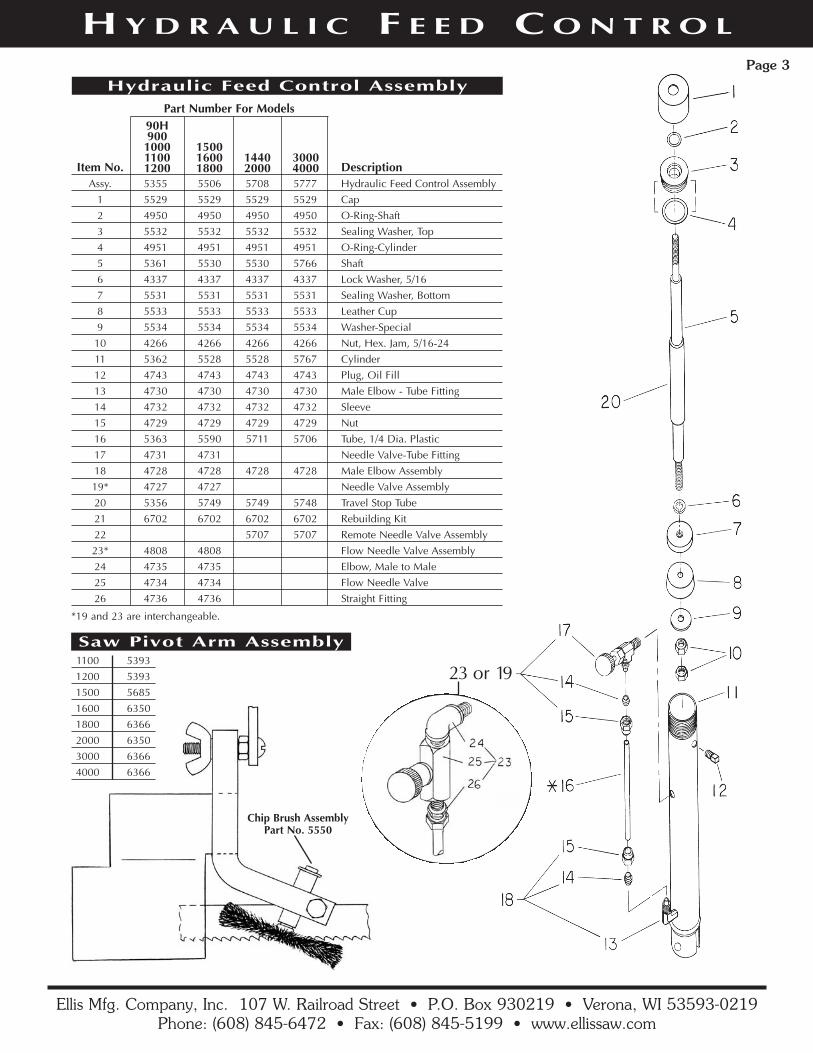
H Y D R A U L I C F E E D C O N T R O LPage 3
Ellis Mfg. Company, Inc. 107 W. Railroad Street • P.O. Box 930219 • Verona, WI 53593-0219Phone: (608) 845-6472 • Fax: (608) 845-5199 • www.ellissaw.com
Part Number For Models
150016001800
90H900100011001200
14402000
30004000Item No. Description
Assy. 5355 5506 5708 5777 Hydraulic Feed Control Assembly1 5529 5529 5529 5529 Cap2 4950 4950 4950 4950 O-Ring-Shaft3 5532 5532 5532 5532 Sealing Washer, Top4 4951 4951 4951 4951 O-Ring-Cylinder5 5361 5530 5530 5766 Shaft6 4337 4337 4337 4337 Lock Washer, 5/167 5531 5531 5531 5531 Sealing Washer, Bottom8 5533 5533 5533 5533 Leather Cup9 5534 5534 5534 5534 Washer-Special10 4266 4266 4266 4266 Nut, Hex. Jam, 5/16-2411 5362 5528 5528 5767 Cylinder12 4743 4743 4743 4743 Plug, Oil Fill13 4730 4730 4730 4730 Male Elbow - Tube Fitting14 4732 4732 4732 4732 Sleeve15 4729 4729 4729 4729 Nut16 5363 5590 5711 5706 Tube, 1/4 Dia. Plastic17 4731 4731 Needle Valve-Tube Fitting18 4728 4728 4728 4728 Male Elbow Assembly19* 4727 4727 Needle Valve Assembly20 5356 5749 5749 5748 Travel Stop Tube21 6702 6702 6702 6702 Rebuilding Kit22 5707 5707 Remote Needle Valve Assembly23* 4808 4808 Flow Needle Valve Assembly24 4735 4735 Elbow, Male to Male25 4734 4734 Flow Needle Valve26 4736 4736 Straight Fitting
Hydraulic Feed Control Assembly
Saw Pivot Arm Assembly
Chip Brush AssemblyPart No. 5550
1100 53931200 53931500 56851600 63501800 63662000 63503000 63664000 6366
*19 and 23 are interchangeable.
23 or 19

Description5367 5740 5775 Drive Wheel With Rubber
Page 4
Item PartNo. No. Description
1 4966 Mitre Head Locking Handle2 4311 Flat Washer
Press center button to reset ratchet in Handle
Mitre Head Locking HandleALL MODEL SAWS
Part Number For Models14401500160018002000
30004000
90H900
100011001200 Description5365 5788 5849 Idler Wheel & Bearing Assy.
Idler Wheel and Bearing Assy.With Vulcanized Rubber
Part Number For Models14401500160018002000
30004000
90H900
100011001200
Drive Wheel WithVulcanized Rubber
Part Number For Models1100120015001600
1800200030004000
90H1000
ItemNo. Description
1 4500 4510 4514 Carrier Guide, 4 Reqd.2 4499 4522 4522 Thrust Ball Bearing, 2 Reqd.
Bearing Carrier Assembly
1
2

I N S T A L L A T I O N & O P E R A T I O NPage 5
Installation Instructions1. Visually inspect machine for hidden shipping damage.
2. As part of the receiving inspection, check for broken ballbearings on the bearing carrier assembly. This is the assem-
bly that the saw swivels on for miter cuts. CHECK ALL SIXBEARINGS. Two are located in the groove under thedegree plate. See illustration on page 4.
Vertical Sawing PositionNOTE: Model 1800 only – before raising the head on theModel 1800, remove the head weight adjustment hand-wheel and install the 6021 T-Nut. Attach the threadedvertical support bar (6022) tightly to the rear of the drivehousing. See the chart on page 8. Adjust, if needed, tosquare blade with the vertical table.
1. Pull hydraulic pin at bottom of hydraulic. Disengage com-pensating spring assembly. Head is now free to raise to ver-tical position. Raise head up and over center. Hold headand gently let it move up to vertical position. DON’T LETTHE HEAD DROP! See illustration on page 8, or video.
2. Slide the vertical saw table into the blade and against theback of the horizontal table. Secure with the screwless viseor C-clamps. Adjust the drive end of the blade guide assem-bly, if necessary, to provide support for that end of the ver-tical table.
3. Attach the vertical blade guard on the moveable guide armand secure with wing nut supplied.
4. Position moveable arm as close to work as possible.
Removing and Replacing BladeCall 1-800-383-5547 for experienced help in selecting theproper saw blades for your application.
1. Disconnect power supply cord from power source.
2. Raise saw head assembly until blade clears the back of thetable. Close hydraulic valve to lock in position.
3. Open the covers of the idler and drive wheels.
4. Pivot the chip brush to horizontal position and lock in place.
5. Loosen blade tension T-handle sufficient to release the bladearound the wheels. Pull blade out of the blade guide bearings.
6. Brush chips from blade guide bearings and housings. Wipebearing surfaces clean. Check that all bearings are running free.
7. Check that the guide bearings are set correctly for the newblade thickness. Use a feeler gauge that is one thousandth ofan inch thicker than the blade. This is the best method becauseit does not rely on judgement.
A saw blade can also be used as a gauge, but it must be new.After the blade has been installed and under proper tension,check for proper spacing. Twist the blade at the idler and drivewheel side of the respective guide bearing housings. Thereshould not be any noticeable motion of the blade on the otherside of the guide bearings. Reset the gap to correct fit.
8. Place the new blade over the idler and drive wheels with theteeth facing toward you. The blade should run under theguides. The teeth should point out toward you and the tips ofthe teeth should point toward the motor end of the saw.
A fast check is to compare the blade (as you place it over theidler wheel) with the decal on the top of the saw head. Checkto make sure the blade is on both orange wheels.
9. By turning the T-Handle, apply tension to the blade until allslack is removed from the blade or the blade is pulled in astraight line across the top of the saw from wheel to wheel.Grasp the blade on each side of the guides and twist theblade. Push down on the teeth with your thumbs and roll theback of the blade between the guide bearings. Proper tensionis 1-1/2 to 2 full turns (360) of the T-Handle.
10. Proper blade tension is reached by grasping the T-Handle andapplying one full turn (360) on the tension handle. You canuse the casting number on the handle as a reference point.Reconnect the power supply. Turn the saw on for a couple ofrevolutions to square the blade on the wheels. Turn the sawoff. Now put the second full turn of tension on the T-Handle.
Turn the saw on again for a few revolutions. Turn the sawoff. Check the tracking of the blade on the wheels. On sawswith a 9" wheel the blade runs centered on the wheels. Onsaws with 12" and 14" wheels the teeth of the blade shouldbe sticking out past the edge of the wheel. The teeth shouldnot be on the rubber of the idler or drive wheels. If the bladeis not tracking properly then the idle wheel needs to beadjusted. If you think the idle wheel needs to be adjusted, callthe factory at 1-800-383-5547 for assistance.
11. Check the blade tension by setting the guide housings about8" apart then grasp the blade between the fingers and thumbhalfway between the guide housings. With a rotating or twisting motion of the hand the blade should deflect no morethan 1/8".
A video is available showing the proper procedure forremoving and replacing blades, saw adjustments, trou-bleshooting and maintenance. If you did not receive avideo with this machine or would like another copy, callthe factory.
Disconnect power supply cord from power source beforechanging the blade or making any other repair or adjustment to the saw.
IMPORTANT Model 2000, 3000 and 4000 owners note: The shut off rail was removedfor shipping. You must mount the rail on the machine table before using the saw.

I N S T A L L A T I O N & O P E R A T I O NPage 6
Troubleshooting Crooked Cuts1. Check blade for worn or broken teeth and replace if needed.
2. Check to make sure that the number of teeth per inch on theblade fit the application. As a rule, only 6 to 12 teeth shouldbe in contact with the workpiece.
3. Check the head pressure on the saw. The compensatingspring tension should be 8 pounds with the blade 1" abovethe table, coming down with the hydraulic valve open.
4. Check the blade tension. Review the proper blade tensionprocedure under “Removing and Replacing Blade” on page5, item 10.
5. Check the space between bearings of both guide bearingassemblies. It should be only .001" over the thickness of a
new blade. As an example, a .033" feeler gauge would beused to set the guides for a .032" thick blade.
6. Check the blade tracking on the idler and drive wheels.
9" solid wheels: blade in center of wheels
12" spoked wheels: 3/4" wide blade should have teethprotruding from the side of the wheel about 1/8", andthe 1" wide blade about 1/4".
14" spoked wheels: 1" and 1-1/4" wide blades shouldhave teeth protruding 1/4" to 5/16" from side of wheel.
7. Check to make sure that the blade guide assemblies are nottoo far apart. Set the idler blade guide closer to the work toprovide greater support for the blade.
Saw Adjustments
1. Squaring blade with back of saw table.
Raise the head up 1/8" and hold in place with the hydraulicvalve. Place a 6" square against the table back and move thehead until the blade is exactly 90 degrees from the tableback. Lock the head in position. Check that the POINTERpoints to zero (0 degrees) on the degree plate. If the pointerdoes not point to zero, bend the pointer so that it lines up to0 degrees. The saw is now adjusted to cut from front to backaccurately at 90 degrees and at all angles.
2. Square blade with top of saw table.
Use a blade aligning tool of the “clip on” or magnetic type toattach to the blade. Set a 6" square on the table top with theblade vertical and touching the aligning tool. These test
measurements should be made with the tools kept as close aspossible to the guide bodies. If the blade is not square withthe table, the guide bearing plate needs to be adjusted tobring the blade into alignment. See illustration of BladeGuide Assembly on page 2.
First the wing nut, Item 9 in the illustration, must be loos-ened. Next, loosen nut, Item 13. The adjustment to the bear-ing plate is set using the cap screw, Item 14. If the adjust-ment requires that the cap screw be backed out, the adjust-ment stud, Item 2, must be manually pushed so it is in con-tact with the cap screw. When the blade is aligned parallelwith the square, tighten the wing nut to lock the bearingplate in position. Hold the cap screw from turning and locknut, Item 13, against the guide clamping bolt.
Blade Speeds
The V-belt must be changed on the pulleys to change speeds.For HIGH speed, place the belt in the largest pulley on themotor shaft and the smallest on the reducer shaft.
For MEDIUM speed, the middle pulley is used on both shafts.For LOW speed, the smallest pulley on the motor shaft is usedwith the largest on the reducer.
Replacement of Hydraulic Oil
The hydraulic cylinder can be filled on the saw or in a benchvise.
THE SHAFT MUST BE FULLY PUSHED IN BEFORE STARTING TO FILL.
1. Remove pipe plug from near top of cylinder.
2. Fill with light weight hydraulic oil until oil flows back out ofhole. Replace pipe plug.
Maintenance
A good clean machine is easy to operate and promotes safety.
1. Keep areas clean by brushing chips from table grooves,guide bodies, idler and drive wheels, pivot shaft hinge areaand turntable grooves.
2. Oilite bushings in pivot shaft should be oiled annually.
3. Check oil level in hydraulic. Proper level is at pipe plug hole.
4. Oil in wormgear should be checked every 90 days. FILL TOPROPER LEVEL AT PLUG, BELOW THE BREATHERVENT, using 80 to 140 weight gear oil.
(If above steps did not eliminate crooked cuts)

A I R C O O L I N GPage 7
Part NumberFor Voltage Rating
230120Item No. DescriptionSys. 5922 5932 Air Cooling System-Complete1 5925 5925 Valve and Nozzle Assembly2 4730 4730 Elbow Fitting3 4733 4733 Needle Valve4 4744 4744 Nipple5 5923 5923 Mounting Bar*6 5924 5924 Nozzle Cap7 4970 4970 Blow Gun8 4969 4969 Air Hose Assembly9 5903 5912 Solenoid Valve Assembly-Complete10 5904 5913 Solenoid and Cord Assembly Only11 5926 5926 Tubing, .25 OD, 5 Feet12 4015 4015 Bolt, Hex. Head 5/16-18 x 1-1/4
Air Cooling System
* For saw Model 4000 use mounting bar 5928
ENLARGEMENTOF AIR NOZZLE
Air Supply Tube
Connect To Shop Air
Power Cord ToReceptacle On Band Saw
Air Tube BetweenSolenoid AndAir Nozzle
Saw Blade
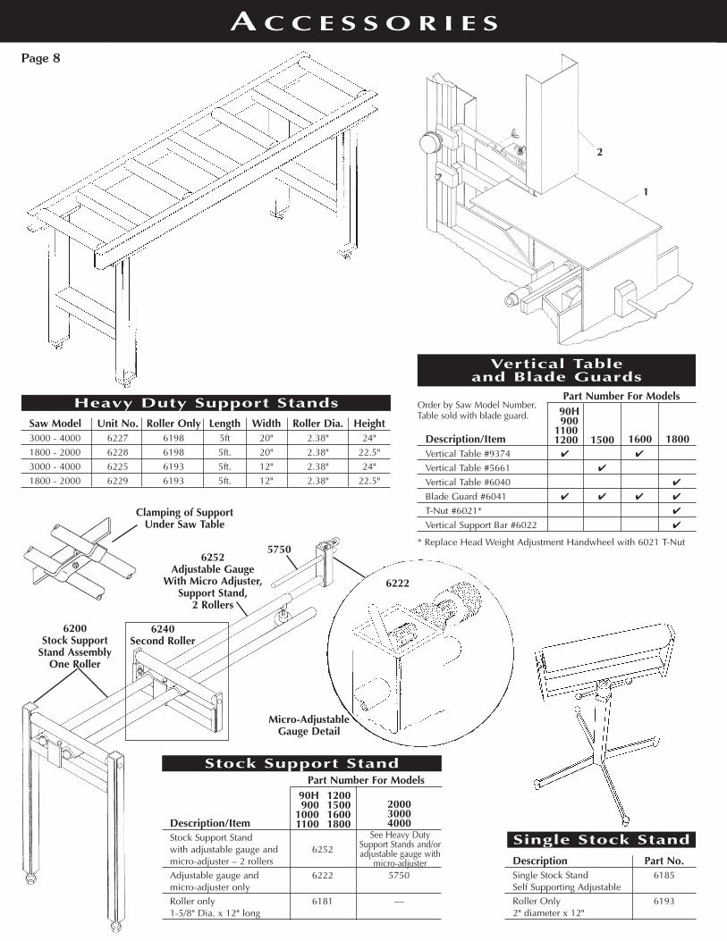
A C C E S S O R I E SPage 8
Part Number For Models
1500
90H900
11001200 1600 1800Description/Item
Vertical Table #9374 ✔ ✔
Vertical Table #5661 ✔
Vertical Table #6040 ✔
Blade Guard #6041 ✔ ✔ ✔ ✔
T-Nut #6021* ✔
Vertical Support Bar #6022 ✔
Vertical Table and Blade Guards
Order by Saw Model Number.Table sold with blade guard.
* Replace Head Weight Adjustment Handwheel with 6021 T-Nut
Part Number For Models90H 1200900 1500
1000 16001100 1800
200030004000Description/Item
Stock Support Standwith adjustable gauge and 6252micro-adjuster – 2 rollersAdjustable gauge and 6222 5750micro-adjuster onlyRoller only 6181 —1-5/8" Dia. x 12" long
Stock Support Stand
Description Part No.Single Stock Stand 6185Self Supporting AdjustableRoller Only 61932" diameter x 12"
Single Stock Stand
Saw Model Unit No. Roller Only Length Width Roller Dia. Height3000 - 4000 6227 6198 5ft 20" 2.38" 24"1800 - 2000 6228 6198 5ft. 20" 2.38" 22.5"3000 - 4000 6225 6193 5ft. 12" 2.38" 24"1800 - 2000 6229 6193 5ft. 12" 2.38" 22.5"
Heavy Duty Support Stands
1
2
6252 Adjustable Gauge
With Micro Adjuster,Support Stand,
2 Rollers
Micro-AdjustableGauge Detail
6200 Stock Support
Stand AssemblyOne Roller
6240 Second Roller
5750
6222
See Heavy DutySupport Stands and/oradjustable gauge with
micro-adjuster
Clamping of SupportUnder Saw Table