Installation and Operating Instructions - Franklin · PDF fileInstallation and Operating...
8
Installation and Operating Instructions Congratulations on your purchase of a Franklin Electric pump protection system. Pumptec-Plus is the most sophisticated pump protection system on market today. It is designed to work on any 230 VAC single phase induction motor (PSC, CSCR, CSIR and split phase) ranging in size from 0.37 to 3.7kW. Your pump protection unit uses a microcomputer to continuously monitor power and line voltage to pro- vide protection agains dry well conditions, waterlogged tank, high or low line voltage, and mud or sand clogging. Indicator lights provide complete system status and are easily viewed without removing the cover. A 3.7kW rated contactor is included with the unit. The control box provides large terminal blocks and plenty of room for wiring, even when using 25mm wire. Our unique Snapshot calibration feature pro- vides simple, reliable push-button calibration. PLEASE READ THESE INSTRUCTIONS CAREFULLY BEFORE INSTALLING THE UNIT. FEATURES ■ Over/Underload Protection ■ Over/Under Voltage Protection ■ Rapid Cycle Detection ■ Fault Indicator Lights ■ Run Indicator Light ■ 3.7kW Contactor ■ Heavy Duty Terminal Blocks ■ Adjustable Automatic Restart Timer ■ Snapshot Calibration ■ Continuous Calibration Memory ■ Works With All Single Phase Motors ■ Transient Surge Protection ■ Patent Pending ■ Toll-Free Customer Support (1300 FRANKLIN)
-
Upload
duongkhanh -
Category
Documents
-
view
219 -
download
2
Transcript of Installation and Operating Instructions - Franklin · PDF fileInstallation and Operating...

PUMP PROTECTION SYSTEM
Installation and Operating InstructionsCongratulations on your purchase of a Franklin Electric pump protection system. Pumptec-Plus is the mostsophisticated pump protection system on market today. It is designed to work on any 230 VAC single phase induction motor (PSC, CSCR, CSIR and split phase) ranging in size from 1/2 to 5 horsepower.
Your pump protection unit uses a microcomputer to continuously monitor power and line voltage to provide protection agains dry well conditions, waterlogged tank, high or low line voltage, and mud or sand clogging. Indicator lights provide complete system status and are easily viewed without removing the cover. A 5 horsepower rated contactor is included with the unit. The control box provides large terminal blocks and plenty of room for wiring, even when using #2 wire. Our unique Snapshot calibration feature provides simple, reliable push-button calibration.
PLEASE READ THESE INSTRUCTIONS CAREFULLY BEFORE INSTALLING THE UNIT.
FEATURES
� Over/Underload Protection� Over/Under Voltage Protection� Rapid Cycle Detection� Fault Indicator Lights� Run Indicator Light� 5 hp Contactor� Heavy Duty Terminal Blocks� Adjustable Automatic Restart Timer� Snapshot Calibration� Continuous Calibration Memory� Works With All Single Phase Motors� Transient Surge Protection� Patent Pending� UL Listed (E104778)� Toll-Free Customer Support (800 348 2420)
400 East Spring StreetBluffton, Indiana 46714Tel: 260 824 2900, Fax: 260 824 2909www.franklin-electric.com
Installation and Operating InstructionsCongratulations on your purchase of a Franklin Electric pump protection system. Pumptec-Plus is the most sophisticated pump protection system on market today. It is designed to work on any 230 VAC single phase induction motor (PSC, CSCR, CSIR and split phase) ranging in size from 0.37 to 3.7kW.
Your pump protection unit uses a microcomputer to continuously monitor power and line voltage to pro-vide protection agains dry well conditions, waterlogged tank, high or low line voltage, and mud or sand clogging. Indicator lights provide complete system status and are easily viewed without removing the cover. A 3.7kW rated contactor is included with the unit. The control box provides large terminal blocks and plenty of room for wiring, even when using 25mm wire. Our unique Snapshot calibration feature pro-vides simple, reliable push-button calibration.
PLEASE READ THESE INSTRUCTIONS CAREFULLY BEFORE INSTALLING THE UNIT.
FEATURES■ Over/Underload Protection
■ Over/Under Voltage Protection
■ Rapid Cycle Detection
■ Fault Indicator Lights
■ Run Indicator Light
■ 3.7kW Contactor
■ Heavy Duty Terminal Blocks
■ Adjustable Automatic Restart Timer
■ Snapshot Calibration
■ Continuous Calibration Memory
■ Works With All Single Phase Motors
■ Transient Surge Protection
■ Patent Pending
■ Toll-Free Customer Support (1300 FRANKLIN)

INSTALLATION INFORMATION
INSTALLATION
WARNING: To avoid possible fatal shock, disconnect power at the main power panel before installing, wiring, or servicing Pumptec-Plus.
Horsepower Rating ........................... 0.37 to 3.7kW
Operating Voltage .................................... 230 VAC
Operating Frequency ......................................50 Hz
Power Consumption .....................................5 Watts
Operating Temperature Range ......... -26 °C to 60°C
Over/Under Voltage Trip ................................± 10%
Over/Under Load Trip ...................................± 25%*
Rapid Cycle Trip .....................................4 starts/min
Trip Response Time ...................................... 2.5 sec
Automatic Restart Time ........ 1 min to 4 hr 15 min
Over/Under Voltage Retry ..............................2 min
Calibration Abort Time ...................................3 min
Calibration Memory .....................................10 years
Contactor Rating .............................................3.7kW* Percent of load time of calibration SNAPSHOTTE
CHNI
CAL
SPEC
IFIC
ATIO
NS
2
CAUTION: This product does not replace a motor control box or the need for motor overload protection. Motor overload protection should be in accordance with National Electrical Code Article 430 or in accordance with motor manufacturer’s recommendations.
NOTE: This unit requires calibration before operation. Calibration is described in step 7 of the installation instructions.
7 8
90
13 2
45
6
FRONT COVER SCREW
7 8
90
13 2
45
6
FRONT COVER SCREW
1. REMOVE COVERRemove the Pumptec-Plus cover by removing the cover screw and sliding the cover up. Place cover in a safe location.
2. SET THE TIMER SWITCHSet the automatic timer switch to the desired reset time. This will reset the time after an underload trip condition (dry well condition) has occurred until the Pumptec-Plus will try to restart the motor.
TIMER SWITCH SETTINGS
0) Manual Reset 5) 16 Minutes1) 1 Minute 6) 32 Minutes2) 2 Minutes 7) 1 Hour 4 Minutes3) 4 Minutes 8) 2 Hours 8 Minutes4) 8 Minutes 9) 4 Hours 16 Minutes
3
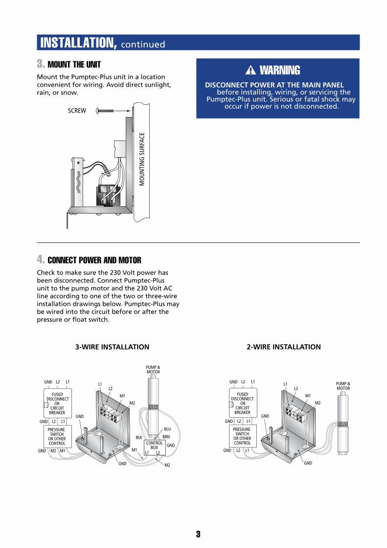
3. MOUNT THE UNITMount the Pumptec-Plus unit in a location convenient for wiring. Avoid direct sunlight, rain, or snow.
4. CONNECT POWER AND MOTORCheck to make sure the 230 Volt power has been disconnected. Connect Pumptec-Plus unit to the pump motor and the 230 Volt AC line according to one of the two or three-wire installation drawings below. Pumptec-Plus may be wired into the circuit before or after the pressure or float switch.
INSTALLATION, continued
MO
UNTI
NG
SUR
FACE
SCREW
PRESSURESWITCH
OR OTHERCONTROL
FUSEDDISCONNECT
ORCIRCUIT
BREAKER
GND
GND
GND
GND
L2
L2
M1
M2
M2
L1 L1
GND
GND M2 M1 M1
L2 L1
BLK
PUMP &MOTOR
BLU
BRNCONTROL
BOXL1 L2
PRESSURESWITCH
OR OTHERCONTROL
FUSEDDISCONNECT
ORCIRCUIT
BREAKER
GND
GND
GND
L2
L2
M1
M2
L1 L1
GND
GND L2 L1
L2 L1
PUMP &MOTOR
3-WIRE INSTALLATION 2-WIRE INSTALLATION
INSTALLATION, continued
OPERATION
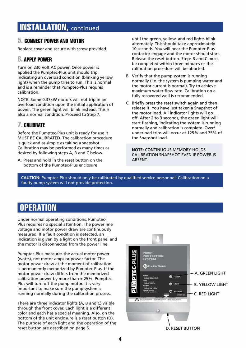
5. CONNECT POWER AND MOTORReplace cover and secure with screw provided.
6. APPLY POWERTurn on 230 Volt AC power. Once power is applied the Pumptec-Plus unit should trip, indicating an overload condition (blinking yellow light) when the pump tries to run. This is normal and is a reminder that Pumptec-Plus requres calibration.
NOTE: Some 0.37kW motors will not trip in an overload condition upon the initial application of power. The green light will blink instead. This is also a normal condition. Proceed to Step 7.
7. CALIBRATEBefore the Pumptec-Plus unit is ready for use it MUST BE CALIBRATED. The calibration procedure is quick and as simple as taking a snapshot. Calibration may be performed as many times as desired by following steps A, B and C below.
A. Press and hold in the reset button on the bottom of the Pumptec-Plus enclosure
until the green, yellow, and red lights blink alternately. This should take approximately 10 seconds. You will hear the Pumptec-Plus contactor engage and the motor should start. Release the reset button. Steps B and C must be completed within three minutes or the calibration procedure will be aborted.
B. Verify that the pump system is running normally (i.e. the system is pumping water and the motor current is normal). Try to achieve maximum water flow rate. Calibration on a fully recovered well is recommended.
C. Briefly press the reset switch again and then release it. You have just taken a Snapshot of the motor load. All indicator lights will go off. After 2 to 3 seconds, the green light will start flashing, indicating the system is running normally and calibration is complete. Over/underload trips will occur at 125% and 75% of the Snapshot load.
NOTE: CONTINUOUS MEMORY HOLDS CALIBRATION SNAPSHOT EVEN IF POWER IS ABSENT.
Under normal operating conditions, Pumptec-Plus requires no special attention. The power line voltage and motor power draw are continuously measured. If a fault condition is detected, an indication is given by a light on the front panel and the motor is disconnected from the power line.
Pumptec-Plus measures the actual motor power (watts), not motor amps or power factor. The motor power draw at the moment of calibration is permanently memorized by Pumptec-Plus. If the motor power draw differs from the memorized calibration power by more than ± 25%, Pumptec-Plus will turn off the pump motor. It is very important to make sure the pump system is running normally during the calibration process.
There are three indicator lights (A, B and C) visible through the front cover. Each light is a different color and each has a special meaning. Also, on the bottom of the unit enclosure is a reset button (D). The purpose of each light and the operation of the reset button are described on page 5.
4
CAUTION: Pumptec-Plus should only be calibrated by qualified service personnel. Calibration on a faulty pump system will not provide protection.
ed service personnel. Calibration on a
A. GREEN LIGHT
B. YELLOW LIGHT
C. RED LIGHT
D. RESET BUTTON

OPERATION, continued
A. GREEN LIGHTThe green light (A) indicates that the status of the pump system is normal.
A SOLID GREEN LIGHT indicates that Pumptec-Plus has power and the contactor to the motor is closed but the motor is not running. This may happen when the pressure switch is wired in down-line from Pumptec-Plus and the switch is open. Pumptec-Plus is waiting for the pressure switch to close.
A FLASHING GREEN LIGHT indicates the pump motor is running normally and drawing the correct amount of power.
B. YELLOW LIGHTThe yellow light (B) indicates that a load fault has occurred.
A SOLID YELLOW LIGHT indcates an underload fault occurred. The Pumptec-Plus automatic restart timer will restart the motor in accordance with the position of the automatic restart timer switch setting. The switch should be set at the time of installation (refer to Step 2). If set in the manual position, Pumptec-Plus must be reset manually by pushing the RESET BUTTON (D).
A FLASHING YELLOW LIGHT indicates an overload condition occurred. This means that the pump system power draw was greater than the normal operating power (calibration) by more than 25% for more than 2.5 seconds. Pumptec-Plus will not run the pump system again until the RESET BUTTON (D) is pressed.
C. RED LIGHTThe red light (C) indicates a line voltage fault occurred and Pumptec-Plus has turned off the pump motor.
A SOLID RED LIGHT indicates an under voltage condition (line< 207 VAC) existed for more than 2.5 seconds. Pumptec-Plus will automatically try to reset the motor within two minutes. The RESET BUTTON (D) may also be pressed to clear this condition.
A FLASHING RED LIGHT indicates an over voltage condition (line> 253 VAC) has existed more than 2.5 seconds. Pumptec-Plus will automatically try to reset the motor within two minutes. The RESET BUTTON (D) may also be pressed to clear this condition.
B&C. RED AND YELLOW FLASHING LIGHTSIf the RED and YELLOW lights (B&C) are flashing on and off together, a rapid cycle condition was detected. A rapid cycle condition is defined as more than four motor starts per minute.
D. RESET BUTTONThe reset button is used to restart the Pumptec-Plus from a tripped condition. Pressing the reset button for less than ten seconds has no effect on the calibration. Simply press and release the button. The unit will reset.
Pressing the reset button for more than 10 seconds will cause the unit to go into the calibration mode. A rotating light sequence from green to yellow to red will begin. At this point, the contactor closes and the motor will start to run. The unit will stay in the calibration mode for 3 minutes or until the reset button is pressed again.
If after three minutes the reset button is not pressed, the unit will revert back to its normal running mode, making no changes to the calibration.
Pressing the reset button before the three minute period expires, will cause the unit to recalibrate to the motor load present at the time the reset button is pressed the second time.
5
OPERATION, continued
RESET BUTTON
OPERATION, continued
RESET BUTTON
OPERATION, continued
RESET BUTTON
OPERATION, continued
RESET BUTTON
OPERATION, continued
RESET BUTTON
6
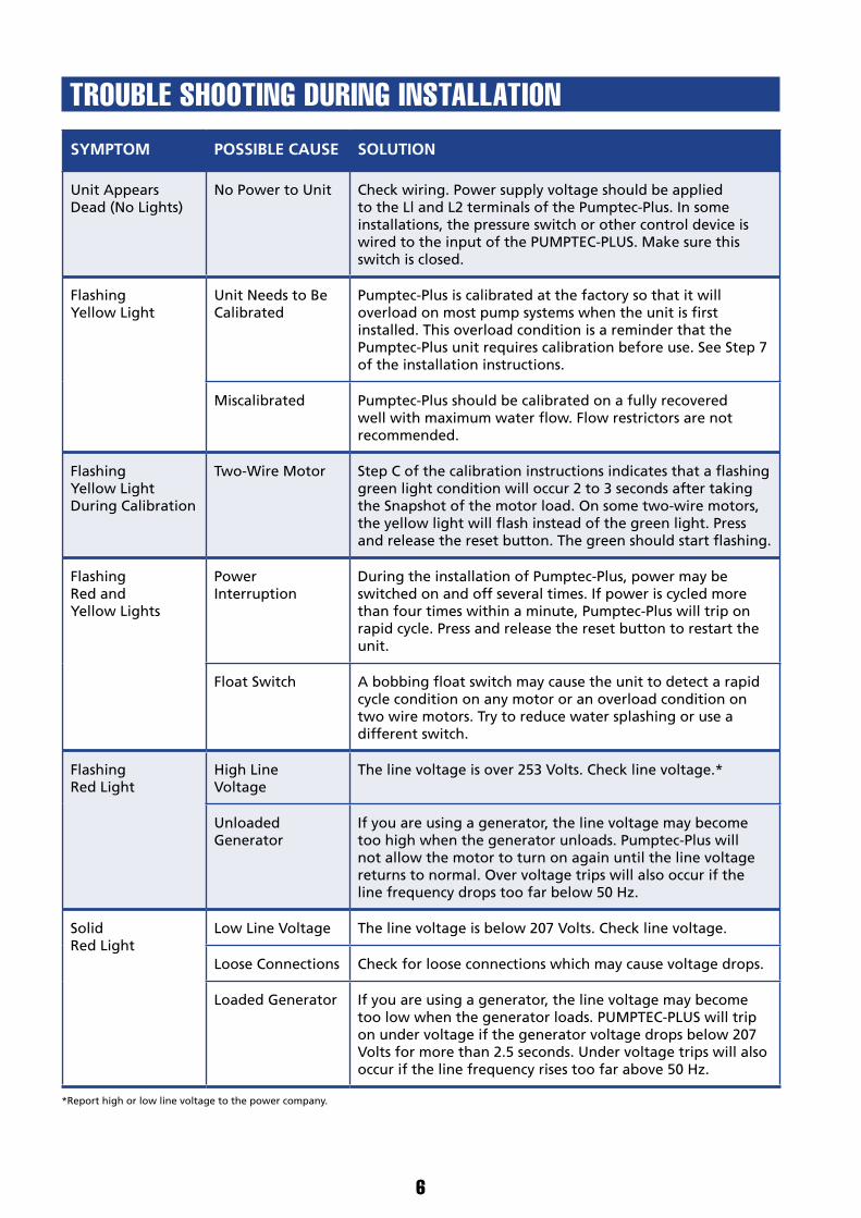
TROUBLE SHOOTING DURING INSTALLATIONSYMPTOM POSSIBLE CAUSE SOLUTION
Unit Appears Dead (No Lights)
No Power to Unit Check wiring. Power supply voltage should be applied to the Ll and L2 terminals of the Pumptec-Plus. In some installations, the pressure switch or other control device is wired to the input of the PUMPTEC-PLUS. Make sure this switch is closed.
Flashing Yellow Light
Unit Needs to Be Calibrated
Pumptec-Plus is calibrated at the factory so that it will overload on most pump systems when the unit is first installed. This overload condition is a reminder that the Pumptec-Plus unit requires calibration before use. See Step 7 of the installation instructions.
Miscalibrated Pumptec-Plus should be calibrated on a fully recovered well with maximum water flow. Flow restrictors are not recommended.
Flashing Yellow Light During Calibration
Two-Wire Motor Step C of the calibration instructions indicates that a flashing green light condition will occur 2 to 3 seconds after taking the Snapshot of the motor load. On some two-wire motors, the yellow light will flash instead of the green light. Press and release the reset button. The green should start flashing.
Flashing Red and Yellow Lights
Power Interruption
During the installation of Pumptec-Plus, power may be switched on and off several times. If power is cycled more than four times within a minute, Pumptec-Plus will trip on rapid cycle. Press and release the reset button to restart the unit.
Float Switch A bobbing float switch may cause the unit to detect a rapid cycle condition on any motor or an overload condition on two wire motors. Try to reduce water splashing or use a different switch.
Flashing Red Light
High Line Voltage
The line voltage is over 253 Volts. Check line voltage.*
Unloaded Generator
If you are using a generator, the line voltage may become too high when the generator unloads. Pumptec-Plus will not allow the motor to turn on again until the line voltage returns to normal. Over voltage trips will also occur if the line frequency drops too far below 50 Hz.
Solid Red Light
Low Line Voltage The line voltage is below 207 Volts. Check line voltage.
Loose Connections Check for loose connections which may cause voltage drops.
Loaded Generator If you are using a generator, the line voltage may become too low when the generator loads. PUMPTEC-PLUS will trip on under voltage if the generator voltage drops below 207 Volts for more than 2.5 seconds. Under voltage trips will also occur if the line frequency rises too far above 50 Hz.
*Report high or low line voltage to the power company.
7
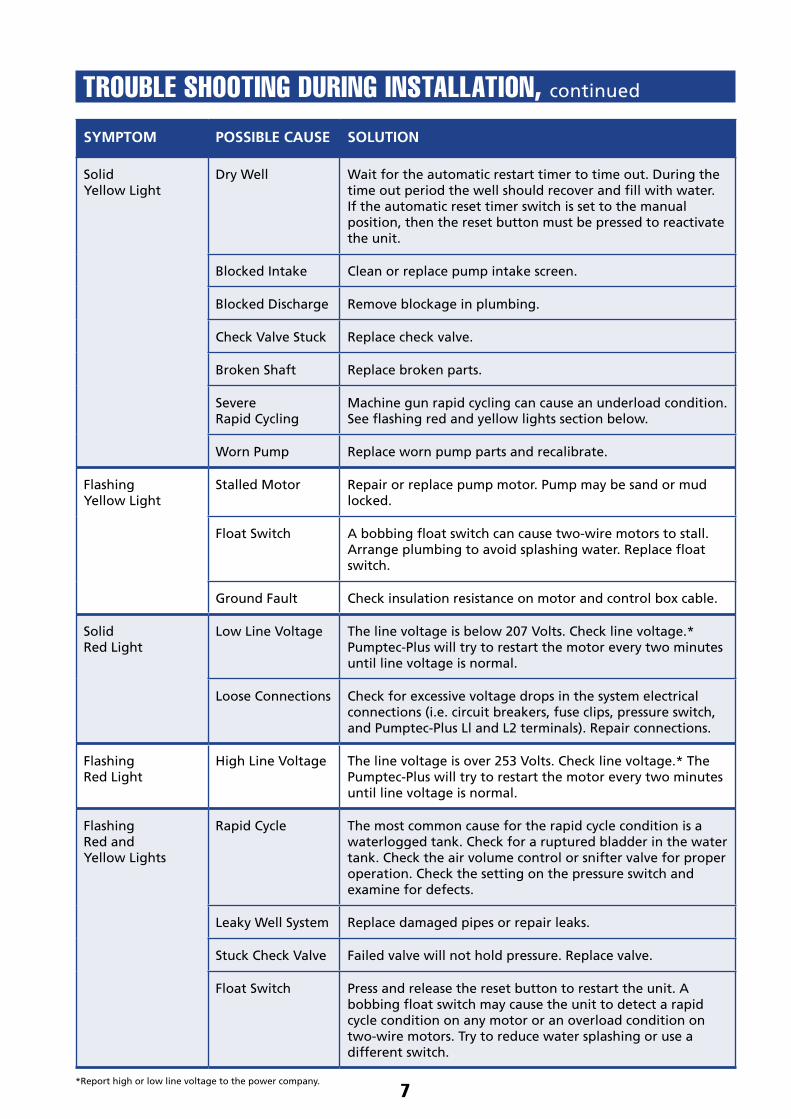
TROUBLE SHOOTING DURING INSTALLATION, continued
SYMPTOM POSSIBLE CAUSE SOLUTION
Solid Yellow Light
Dry Well Wait for the automatic restart timer to time out. During the time out period the well should recover and fill with water. If the automatic reset timer switch is set to the manual position, then the reset button must be pressed to reactivate the unit.
Blocked Intake Clean or replace pump intake screen.
Blocked Discharge Remove blockage in plumbing.
Check Valve Stuck Replace check valve.
Broken Shaft Replace broken parts.
Severe Rapid Cycling
Machine gun rapid cycling can cause an underload condition. See flashing red and yellow lights section below.
Worn Pump Replace worn pump parts and recalibrate.
Flashing Yellow Light
Stalled Motor Repair or replace pump motor. Pump may be sand or mud locked.
Float Switch A bobbing float switch can cause two-wire motors to stall. Arrange plumbing to avoid splashing water. Replace float switch.
Ground Fault Check insulation resistance on motor and control box cable.
Solid Red Light
Low Line Voltage The line voltage is below 207 Volts. Check line voltage.* Pumptec-Plus will try to restart the motor every two minutes until line voltage is normal.
Loose Connections Check for excessive voltage drops in the system electrical connections (i.e. circuit breakers, fuse clips, pressure switch, and Pumptec-Plus Ll and L2 terminals). Repair connections.
Flashing Red Light
High Line Voltage The line voltage is over 253 Volts. Check line voltage.* The Pumptec-Plus will try to restart the motor every two minutes until line voltage is normal.
Flashing Red and Yellow Lights
Rapid Cycle The most common cause for the rapid cycle condition is a waterlogged tank. Check for a ruptured bladder in the water tank. Check the air volume control or snifter valve for proper operation. Check the setting on the pressure switch and examine for defects.
Leaky Well System Replace damaged pipes or repair leaks.
Stuck Check Valve Failed valve will not hold pressure. Replace valve.
Float Switch Press and release the reset button to restart the unit. A bobbing float switch may cause the unit to detect a rapid cycle condition on any motor or an overload condition on two-wire motors. Try to reduce water splashing or use a different switch.
*Report high or low line voltage to the power company.

FE258 05/08
Franklin Electric (Aust) Pty Ltd
106-110 Micro Circuit
Dandenong South, Vic 3175
Tel: +61 3 9799 5000
Toll Free: 1300 FRANKLINfranklin-electric.com.au
TOLL FREE HELP FROM A FRIEND
Phone Franklin’s toll-free Submersible SERVICE HOTLINE for answers to your installation questions. When you call, a Franklin expert will offer assistance in troubleshooting your pump protection system and provide immediate answers to your motor application questions.