Installation and Evaluation of RFID Readers on Moving...
10
Installation and Evaluation of RFID Readers on Moving Vehicles * Eun-Kyu Lee University of California, LA Los Angeles, CA 90095 [email protected] Young Min Yoo Seoul National University, Seoul, Korea [email protected] Chan Gook Park Seoul National University, Seoul, Korea [email protected] Minsoo Kim Electronics and Telecomm. Research Institute, Daejeon, Korea [email protected] Mario Gerla University of California, LA Los Angeles, CA 90095 [email protected] ABSTRACT Due to recent technology advancements, RFID readers have been proposed for several vehicular applications ranging from safe navigation to intelligent transport. However, one ob- stacle to deployment is the unpredictable read performance. An RFID reader occasionally fails to read an RFID tag even in static circumstances, mostly due to collisions. In a mo- bile vehicular environment, latency becomes the key perfor- mance factor because of the high speed of vehicles. This is particularly true when the RFID reader is on the moving vehicle. In this paper, we investigate RFID read latency and thus effectiveness of on-vehicles reader installations for a wide range of speeds. First, we experimentally study the impact of reader and tag relative positions on read errors and read rates. Then we conduct road experiments at varying speeds. The results reveal the critical factors that influence on-vehicle RFID read performance, and give us guidance to identify and pursue directions for improvement. Categories and Subject Descriptors C.4 [Performance of Systems]: Measurement techniques; C.2.1 [Network Architecture and Design]: Wireless com- munication—Vehicular communication General Terms Measurement, Performance, Design, Experimentation Keywords RFID, VANET, Vehicular application, RFID read rate * This research was supported by Ministry of Information and Communication, Republic of Korea. Permission to make digital or hard copies of all or part of this work for personal or classroom use is granted without fee provided that copies are not made or distributed for profit or commercial advantage and that copies bear this notice and the full citation on the first page. To copy otherwise, to republish, to post on servers or to redistribute to lists, requires prior specific permission and/or a fee. VANET’09, September 25, 2009, Beijing, China. Copyright 2009 ACM 978-1-60558-737-0/09/09 ...$10.00. 1. INTRODUCTION Mass production has enabled low cost RFID systems to be distributed over large areas. In production and distribution systems, RFIDs manage products and follow them through- out the delivery route. Data mining is one of the most active research areas where a large number of RFID tags are up- loaded to a server to extract hidden patterns of conveyance. The RFID system is also used in passports for national secu- rity. Norway, Korea, and Germany already produce ePass- port containing the biometric information of the traveler. Healthcare applications make use of RFID systems in vari- ous ways; in a hospital, RFID tags are used to track drugs and assure that patients are given the correct dosages of drugs. To monitor elderly people behavior at home, he/she wears a bracelet equipped with a small RFID reader that reads RFID tags installed everywhere in the apartment, for example toothbrush, faucet, sofa, and bed. In vehicular applications, the RFID tag is generally mounted on the vehicle and the reader on the roadside unit. An Au- tomatic Toll Collection (ATC) system with roadside RFID readers identifies passing vehicles by reading their tags and then charges the fare. The European Union is spending 8.1 million Euros on RFID tracking systems to issue automated tickets for minor traffic violations [1] after reading the Elec- tronic License Plates (ELP) [5]. In these applications, the RFID reader is (almost) stationary while the RFID tags are moving at vehicle speed. This keeps costs low due to cheap price of the RFID tags. In our study, we turn the situa- tion around and ask the question of what happens if the RFID reader is free to move and the tag is fixed. For exam- ple, a vehicle equipped with an RFID reader acquires data from fixed RFID tags while driving. If this is possible, then the driver can collect useful information, e.g. position data, during the trip. A Detailed description of RFID enabled vehicular applications is presented in Section 2. The most significant challenge in the new system is that the fast moving RFID reader accesses RFID tags data with success. RFID read performance is not an issue in a static environment since most read failure at the reader occurs due to collision. Considerable research was spent recently on RFID anti-collision algorithm [13] [15] [22]. Moreover, RFID read performance is not critical in existing fixed read RFID systems since RFID communications occur under highly con-
Transcript of Installation and Evaluation of RFID Readers on Moving...

Installation and Evaluation of RFID Readers on MovingVehicles ∗
Eun-Kyu LeeUniversity of California, LA
Los Angeles, CA [email protected]
Young Min YooSeoul National University,
Seoul, [email protected]
Chan Gook ParkSeoul National University,
Seoul, [email protected]
Minsoo KimElectronics and Telecomm.
Research Institute, Daejeon,Korea
Mario GerlaUniversity of California, LA
Los Angeles, CA [email protected]
ABSTRACTDue to recent technology advancements, RFID readers havebeen proposed for several vehicular applications ranging fromsafe navigation to intelligent transport. However, one ob-stacle to deployment is the unpredictable read performance.An RFID reader occasionally fails to read an RFID tag evenin static circumstances, mostly due to collisions. In a mo-bile vehicular environment, latency becomes the key perfor-mance factor because of the high speed of vehicles. This isparticularly true when the RFID reader is on the movingvehicle. In this paper, we investigate RFID read latencyand thus effectiveness of on-vehicles reader installations fora wide range of speeds. First, we experimentally study theimpact of reader and tag relative positions on read errors andread rates. Then we conduct road experiments at varyingspeeds. The results reveal the critical factors that influenceon-vehicle RFID read performance, and give us guidance toidentify and pursue directions for improvement.
Categories and Subject DescriptorsC.4 [Performance of Systems]: Measurement techniques;C.2.1 [Network Architecture and Design]: Wireless com-munication—Vehicular communication
General TermsMeasurement, Performance, Design, Experimentation
KeywordsRFID, VANET, Vehicular application, RFID read rate
∗This research was supported by Ministry of Informationand Communication, Republic of Korea.
Permission to make digital or hard copies of all or part of this work forpersonal or classroom use is granted without fee provided that copies arenot made or distributed for profit or commercial advantage and that copiesbear this notice and the full citation on the first page. To copy otherwise, torepublish, to post on servers or to redistribute to lists, requires prior specificpermission and/or a fee.VANET’09, September 25, 2009, Beijing, China.Copyright 2009 ACM 978-1-60558-737-0/09/09 ...$10.00.
1. INTRODUCTIONMass production has enabled low cost RFID systems to be
distributed over large areas. In production and distributionsystems, RFIDs manage products and follow them through-out the delivery route. Data mining is one of the most activeresearch areas where a large number of RFID tags are up-loaded to a server to extract hidden patterns of conveyance.The RFID system is also used in passports for national secu-rity. Norway, Korea, and Germany already produce ePass-port containing the biometric information of the traveler.Healthcare applications make use of RFID systems in vari-ous ways; in a hospital, RFID tags are used to track drugsand assure that patients are given the correct dosages ofdrugs. To monitor elderly people behavior at home, he/shewears a bracelet equipped with a small RFID reader thatreads RFID tags installed everywhere in the apartment, forexample toothbrush, faucet, sofa, and bed.
In vehicular applications, the RFID tag is generally mountedon the vehicle and the reader on the roadside unit. An Au-tomatic Toll Collection (ATC) system with roadside RFIDreaders identifies passing vehicles by reading their tags andthen charges the fare. The European Union is spending 8.1million Euros on RFID tracking systems to issue automatedtickets for minor traffic violations [1] after reading the Elec-tronic License Plates (ELP) [5]. In these applications, theRFID reader is (almost) stationary while the RFID tags aremoving at vehicle speed. This keeps costs low due to cheapprice of the RFID tags. In our study, we turn the situa-tion around and ask the question of what happens if theRFID reader is free to move and the tag is fixed. For exam-ple, a vehicle equipped with an RFID reader acquires datafrom fixed RFID tags while driving. If this is possible, thenthe driver can collect useful information, e.g. position data,during the trip. A Detailed description of RFID enabledvehicular applications is presented in Section 2.
The most significant challenge in the new system is thatthe fast moving RFID reader accesses RFID tags data withsuccess. RFID read performance is not an issue in a staticenvironment since most read failure at the reader occursdue to collision. Considerable research was spent recently onRFID anti-collision algorithm [13] [15] [22]. Moreover, RFIDread performance is not critical in existing fixed read RFIDsystems since RFID communications occur under highly con-

trolled conditions. For example, in the ATC system, a vehi-cle must pass through a designated gateway and in ELP sys-tem, RFID tag data is examined only when the car stops. Inthe new system, the reader moves at vehicular speed. Thus,RFID read performance at high speeds must be studied be-fore proposing new RFID applications. To our knowledge,this is the first study that evaluates RFID read performancein a road testbed. Our contributions in this paper are thefollowing. First, we investigate RFID device in terms ofdata rate and pause time. These parameters are expectedto directly affect RFID read performance. Next, the phys-ical configuration and installation of the RFID system isevaluated in a real scenario. We run multiple experimentswith RFID reader and antenna installations on the vehiclein different positions and directions. Also, we place RFIDtags on the road at different interval and directions. Lastly,we propose a dual RFID reader antenna and an RFID tagcluster to improve performance based on previous experi-ment results. We verify the performance enhancements ofdual antenna and tag cluster system by comparing with readlatency and read rate in a single antenna RFID system forspeed ranging from 10km/h to 100km/h.
The rest of the paper is organized as follows. In Sec-tion 2, we discuss new vehicular applications enabled by theproposed RFID system. Section 3 reviews the RFID systemfrom the performance viewpoint. Section 4 introduces andexamines the RFID system used in the experiments and itsfactors affecting RFID read performance. In Section 5 lab-oratory experiments are conducted to develop an effectivestrategy for RFID installations on the vehicle and on theroad. RFID read Performance is estimated in a testbed inSection 6. Finally, Section 7 concludes the paper.
2. VEHICULAR RFID APPLICATIONUHF RFID systems have attracted considerable attention
in recent years due to ubiquitous computing applications.Buettner et al. [8] studied the physical and MAC layer of anUHF RFID system to develop a detailed model of RFID pro-tocol operation. They specified factors affecting the RFIDread rate in a static laboratory scenario. In this study, weconsider the UHF RFID system in a vehicular scenario. Inorder to appreciate RFID-enabled vehicular applications, weborrow the taxonomy introduced in [14], namely consumerand producer. An RFID tag provides data to an RFIDreader, thus becomes a data producer, while the reader ob-tains data and utilizes for further applications, i.e. actingas a data consumer. If a server equipped with RFID readercollects data from tags installed on the vehicles and pro-vides traffic information via the Internet, then each vehicleplays a data producer role. More general categorization forvehicular applications can be found in [10].
In the first, more traditional RFID vehicular scenario,the RFID tag is placed on the vehicle. RFID readers aredeployed on roadside units. This architecture reminds usof traditional RFID applications where RFID tags are at-tached on products and stationary RFID readers monitortheir movement. The vehicle, in this case, is a data pro-ducer. The ATC system is the classic example. An RFIDtag on the vehicle is read by Automatic Toll Readers as thevehicle passes by the gateway. The tolling system identifiesthe vehicle and charges the driver accordingly. Many cities,e.g. London and Seoul, operate ATC systems. Pala et al.propose an automatic payment system of parking-fees [16].
The city of Vejle, Denmark, introduced RFID AutomaticVehicle Location (AVI) system in order to enhance the ca-pacity of bus terminals. RFID tags are installed to the frontbumper of buses and RFID readers are embedded in theroad surface along the routes in order to read the uniqueID of passing bus. Passengers are informed of expected busarrival and departure times thus significantly improving thepassenger convenience. Edinburgh Council adopted a bustraffic-light priority system for easing traffic congestion andreducing road accidents. When a bus (or an emergency ve-hicle) equipped with an RFID tag approaches the intersec-tion, a roadside RFID reader captures the bus informationand sends it to the traffic signaling system to control trafficlight. For example, the system can trigger green light foremergency vehicles, e.g. ambulances and fire trucks.
The second, more challenging scenario assumes that thevehicle is equipped with an RFID reader while the RFIDtags are distributed along the road. The vehicle now playsthe data consumer role. Our proposed system falls into thiscategory. In the previously proposed Road Beacon System(RBS), RFID tags are buried in the pavement and an RFIDreader on a vehicle gets road information [4]. The RBSscheme is close to our proposal, but it does not show anyexperimental results. An RFID-based accurate positioningsystem for vehicles was proposed in [9] where an RFID tagis assumed to have accurate position. A vehicle with RFIDreader travels over the RFID tags embedded in the roadand can update its location. If a vehicle gets accurate po-sition from RFID tags deployed on each lane, then a lane-level navigation can be achieved on a freeway. For instance,by reviewing the RFID vehicle readings, one can easily tellwhen vehicles change lanes abruptly near a freeway exit.This happens because a driver does not have sufficient for-warding from vertical and horizontal direction signs. Thisinformation can be helpful to the transportation departmentto design better and more effective signs. Additional inte-gration of lane RFID readings with existing car navigatorfunctionality, i.e. voice warning if the vehicle has declared(through the navigator) the intention to take a particularexit, can greatly enhance driving safety.
A collision avoidance system in urban intersections canalso be effectively supported by vehicle RFID readers andlane RFID tags. A driver entering the 4-way intersectionmay not have noticed a vehicle executing a left turn. Inpoor visibility (eg, foggy night), this can easily lead to anaccident. If vehicles are aware of their accurate positionfrom tags deployed near the intersection and have announcedtheir position via a beacon, the accident can be avoided. An-other promising application of passive lane tags is a wrongway warning. There are many one-way streets in downtownareas. It is important to warn drivers before a head on col-lision occurs. Particularly deadly are the freeway off ramps.It is unfortunately very common for drivers at night to enterthe freeway from the off ramp and drive on the wrong way inthe fast lane with consequences that are easy to imagine. Asthe car reads the lane RFIDs, it immediately realizes thatthey are coming in the wrong sequence, that is, it is goingthe wrong way! Advance wrong way warning will preventthe driver from entering the freeway. Moreover if a vehi-cle notices a wrong way from RFID tag data after entry, itcan automatically broadcast an alarm messages to neighborvehicles to alert them of the possible collision danger.
The increasing penetration of RFID equipped mobile de-

vices in general also facilitates the deployment of RFID ve-hicular applications. In this context, Mobile RFID is definedas a service that provides web based information about ob-jects equipped with an RFID tag [17]. Consider a smartphone with an embedded RFID reader. If the smart phonereads the RFID tag on the bus station billboard, the userreceives information about the bus route via Internet orSMS. Along these lines, authors in [19] and [12] investigatedadaptation of an RFID system into CDMA and WiBro net-works. Nokia offers a Mobile RFID Kit allowing users toaccess phone functions by touching an RFID tag. Anotherimportant safety application is a pedestrian positioning sys-tem [18]. RFID tags, i.e. location markers, are deployedalong a sidewalk. A pedestrian, say, with laptop includingan RFID reader passes by an RFID tag and immediatelygets the accurate position.
In the last scenario, a vehicle is equipped with both anRFID reader (behind the front bumper, say) and RFID tag(on the license plates, say). A vehicle discloses its identityto RFID readers on other vehicles or roadside units, at thesame time acquiring data from them. The ELP (ElectronicLicense Plate) RFID extension is an interesting feature thatlends itself to several applications. For example, consider anautomatic vehicle enforcement system that oversees car lanepriority scheduling and driver compliance. Say, drivers payfor the right to drive on priority lanes. An RFID tag em-bedded in the rear plate contains the plate number. Withthe RFID reader mounted on the front bumper, a vehiclereads the license number of the car in front and reports itto the transport authority. If the car is not authorized, itgets a fine. This peer enforcement becomes more effectiveduring rush hour since traffic is bumper to bumper and anyviolator is detected (and fined) with probability one! As aby-product, peer localization can be achieved when a vehicleannounces its accurate position on the beacon. The bea-con ID and position data (received from neighbors over theradio channel) is correlated to the ELP RFID tag of the ve-hicle in front and the accurate position is then computed.In particular, suppose two vehicles travel in the same direc-tion following one another. Given up to 10-20m of RFIDrange, the position can be computed by the follower withreasonable accuracy.
The above examples have motivated the use of RFID read-ers on vehicles, showing the benefits to safe navigation, ac-cident prevention and even intelligent priority lane manage-ment. The concept of on-board RFID readers is new (cur-rently, the RFID readers are on roadside units only). Thus,it is important to evaluate the feasibility and efficiency ofRFID readers on fast moving platforms. One critical issueis latency induced by high speed. In the following sectionswe address this issue and propose solutions for latency mit-igation.
3. RFID SYSTEMA passive RFID system is composed of a passive RFID
tag storing data and an RFID reader that accesses the tagand collects data. The RFID reader continuously emits RFradio waves and waits for signals back from the tag. Whenthe tag receives the radio waves, it absorbs energy from thewaves, modulates ID data, and sends information back to thereader. This section reviews properties of an RFID systemthat are closely related to RFID communication.
The necessity of external power classifies the RFID sys-
tem; an active RFID tag contains a power module, whereas apassive tag is powered by a radio wave beamed from a reader.An operating frequency determines how energy and data istransmitted; through an inductive coupling or a backscatter-ing coupling. The inductive coupling uses an inductor coil inHF and LF communication. The antenna coil in the readergenerates a magnetic field in a nearby area which gives riseto inductive power in the tag antenna. Current in the tagis so weak, creating a very short transmission range, i.e.around several centimeters. The modulated backscatteringcoupling in UHF bandwidth makes use of the fact that a mi-crowave is reflected by an object whose size is greater thanhalf of the wave length. This enables longer radio range, i.e.approximately up to 10m.
An RFID system suffers from two types of collision, namelya reader and tag collision. The reader collision occurs whenmore than two RFID readers try to access one RFID tag si-multaneously. With Time Division Multiple Access (TDMA),a reader is able to transmit a wave only within the assignedslot [21]. Concurrent transmission of tag data toward asingle RFID reader causes the tag collision. TDMA hasalso provides an anti-collision algorithm in two approaches;ALOHA-based and binary tree-based. In a pure ALOHA al-gorithm, a tag, after receiving a wave, waits for a randomly-generated time period before sending data back [7]. Frameslotted ALOHA (FSA) divides a frame into a fixed numberof slots [22] [15]. Here, one frame is a time period when areader waits for receiving data back from tags after sendinga wave out. The wave contains information on the num-ber of slots, S, in one frame. A tag, when receiving thewave, arbitrarily picks up a random number less than S andtransmits data only during the selected slot period. If twodifferent tags pick the same slot by chance, a collision oc-curs. Then, they try to transmit data again in the nextframe. The binary tree-based algorithm allows a reader tosend a command to a tag [6] [13]. When a collision occurs,the reader selects a number by looking at tag IDs causing thecollision and sends the number to tags. Then, tags whose IDis greater than the number are allowed to send data back tothe reader. The rest tags transmit data in the next round.
This paper studies feasibility of a commercial RFID sys-tem in vehicular environment because of its cost benefit.When exploiting the on-board RFID reader system, i.e. thesecond scenario in Section 2, several questions come up. Thefirst constraint is vehicles’ high speed; can an RFID readeraccess an RFID tag while driving fast? In a freeway, vehi-cles usually drive at faster than 100km/h. This is differentfrom the ATC case because vehicles get slower for safetywhen passing through the toll gateway. In the new system,a vehicle should be allowed to obtain tag data without de-creasing its speed. Therefore, it is fundamental to examinethat an RFID communication can occur in fast moving situ-ation. Chon et al. in [9] studied this issue by dropping RFIDtags down in front of a fixed RFID reader in a laboratory.They estimated that an RFID communication can occur atthe maximum speed of 165km/h. However, real world datais completely different from the laboratory results and weinvestigate it in the later section.
Another constraint comes from a very short communica-tion distance. Unlike the ATC case, i.e. 3m∼4m, the com-munication distance between a reader and a tag could de-crease to less than 30cm since a reader on the front bumperof a vehicle is very close to tags on the road surface. When

Figure 1: An application scenario for measurementof the RFID read rate: a point localization.
considering cone-shaped wave propagation, the short dis-tance creates a small radio area, reducing probability ofsuccessful RFID communication. In addition, the commu-nication area moves fast along with the on-board reader,which also increase uncertainty of communication. In orderto enhance RFID read performance, this paper considers tagmultiplicity and antenna diversity [20].
Erratic mobility of the on-board reader also makes theRFID communication unstable. In the case that a reader isfixed on a roadside, it can be easily calibrated. This con-cept is important because the reader plays an active rolein RFID communication. Therefore, maximizing the RFIDread performance can be achieved. However, a reader in mo-tion is highly likely to access tag data in an arbitrary way.This means that RFID communication could fail at someunpredictable points. For this reason, initial arrangement ofRFID systems is to be inspected carefully to minimize per-formance degradation. In this paper, we explore strategy ofhow to install an RFID system on a vehicle and a roadside.
4. UNDERSTAND RFID READ RATEThis section introduces the RFID system used in our ex-
periments and examines factors affecting the RFID read per-formance. Based on this, we establish a target performanceof the read latency in a vehicular environment. For exper-iments, we draw a simple scenario. We assume that RFIDtags are placed on the road surface along each lane. Eachtag is assumed to have one meaningful data. A vehicle isequipped with a reader and associated antenna(s) and ob-tains RFID data by passing over the tags. For a targetapplication, we consider a point localization, where a vehi-cle acquires its coordinate data by reading tag data whenencountering the tag. Figure 1 illustrates the concept.
The number of tags to be deployed depends on the vehicu-lar application. The tag price (around 10 cents per one tag)and tag intervals could be also taken into account when de-ploying the tags. The RFID tags would not be distributedover all the roads, but we believe that a number of tagsunder an appropriate strategy can be deployed in some spe-cific roads where accidents frequently occur. For example,when we consider ’lane level navigation’ guiding a freewayexit to a driver in this paper, the tags can be placed onlynear the exit. Based on assumption of regional deploymentscenario, this study examines 2m and 5m tag intervals in a3km-length test road for evaluation. If we can assume thateach vehicle is equipped with a GPS device, the number oftags to be deployed is reduced dramatically. In fact, the de-ployment strategy, e.g. deciding the tag numbers, is one ofthe biggest issues in the vehicular RFID applications sinceeach application demands different specification.
Table 1: Hardware specification of the used RFIDsystem.
RFID reader
Frequency 910∼914MHzRF power 4W EIRPRead distance ∼5mModulation ASKRadio access FHSS
RFID readerantenna
Angle 60◦(3dB)Gain 6dBiSize 215(W)×420(L)×55(H)
RFID tagData 64bitData rate 256kbps
Figure 2: RFID system: reader, reader antenna, andtag.
4.1 Hardware of the RFID systemWe select UHF RFID system because of its long read
range and low cost. Table 1 summarizes specification of theRFID system. The RFID reader is KIS900RE [3] operat-ing in 900MHz-914MHz. It supports an anti-collision algo-rithm with Frequency-Hopping Spread Spectrum (FHSS) in200kHz bandwidth. The RFID reader antenna, KIS900AE [3],has 60◦ of angle and 6dBi of gain. The EM4222 chip used inthe RFID tag transmits 64bit data at 256kbps. For anti-collision, each tag waits for a random delay time, pausetime, before sending data out. The maximum pause timeis 62.5ms. Figure 2 shows the RFID system including acomputer collecting and processing RFID data.
4.2 Software Aspect of Specification
4.2.1 Read AreaA previous research revealed that the angle of the used
RFID reader antenna is 68◦, which is a little bit wider thanspecification [9]. Based on this information, we depict aRFID read area, where a reader antenna can communicatea tag to obtain data, as shown in Figure 3. The width (x1)and length (x2) of the area are calculated by Equation 1.
x1 = 2× h× tan 34◦
x2 =h
tan(56◦ + θ◦)+
h
tan(56◦ − θ◦)
(1)
,where h and θ are the height and the pitch angle of thereader antenna (-56◦<θ<56◦). For example, if h = 37.5cmand θ = 45◦, then x1 = 58.58cm and x2 = 185.63cm.

Figure 3: RFID read area.
Table 2: Moving speed of RFID read area (time topass over a RFID tag with h = 37.5cm and θ = 45◦).
Speed [km/h] Computed [sec] Measured [sec]10 0.665 0.36020 0.332 0.18030 0.222 0.12040 0.166 0.09050 0.133 0.07260 0.111 0.06070 0.095 0.05180 0.083 0.04590 0.074 0.040100 0.067 0.036
4.2.2 RFID CommunicationAn RFID communication is a process where an RFID
reader transmits wave to an RFID tag and then receivesdata back from the tag. In order to obtain RFID data, onecommunication, at least, must occur between the reader andthe tag in the read area. Because the reader antenna is at-tached to a vehicle traveling at a high speed, the read areaalso travels and encounters the fixed tags during a shorttime period. One communication should occur at least oncewithin this time period. We define RFID read latency asa time period when one communication occurs and thus areader successfully obtains RFID data from a tag. The readlatency is upper-bounded by vehicles’ speed. In Table 2, wecompute how fast the read area moves from Equation 1. Forcomparison, the third column, i.e. measured [sec], shows re-sults from our experiments. The gap between ’computed’and ’measured’ values is due to the reduced length (x2) ofthe RFID read area in a real situation, which is around 1minstead of 1.85m. The table also indicates that the readlatency should be less than 36ms at the speed of 100km/h.
4.2.3 Data Rate256kbps of data rate of the RFID tag means that it takes
0.22ms to transmit 64bit tag data. Our experiment, how-ever, reveals that the average read latency is 38.89ms. Thisslow communication mainly results from the pause time atthe selected tag whose maximum value is 62.5ms. This im-plies that there might be no RFID communication when avehicle travels at a higher speed than 60km/h since the mov-ing speed of the read area becomes 60ms or shorter (Table 2).
4.2.4 Memory and PacketThe tag chip contains 64bit data memory. The most sig-
nificant 2 bits are reserved, the next 8 bits identify a com-pany producing the tag, and the rest 54 bits including a CRCcode represent the RFID tag ID. The tag initiates a packetcontaining all memory data. Memory size can increase up to2,048 bits if the memory is user-programmable. Therefore,advanced data manipulation can be achieved.
4.3 RFID Read RateIn order to utilize the RFID system on roads, it must
demonstrate reliable performance at a high speed. In orderto appreciate reliability of the RFID system, this paper de-fines RFID read rate as a fraction of RFID tags successfullyread over the total number of tags deployed over a desig-nated test road. When the test road is a 500m-long singlelane and tags are placed every 2m, i.e. 250 tags, 50% ofread rate says that the reader obtains data from 125 tagswhile driving the road. Reliability (or accuracy) is a rela-tive value whose requirement depends on each application.Through experiments, the paper figures out what level ofreliability the commercial RFID system can provide to thetarget application, i.e. point localization.
It is clear that the RFID read rate decreases as speedbecomes faster. As shown in the previous subsections, themoving speed of the read area (36ms at 100km/h) is fasterthan the average read latency measured (38.89ms). Thismeans that the reader is likely to pass by one tag withouthaving one RFID communication, which would degrade re-liability of the RFID system. This is one constraint givenfrom the selected commercial RFID system due to 62.5msof its maximum pause time. One solution is to shorten theaverage read latency to less than 36ms at 100Km/h and theother way is to enlarge the read area to decrease its mov-ing speed. The next section studies such enhancement. Forfine-grained laboratory experiment, we establish, withoutloss of generality, a target performance; an RFID systemshould provide 0.5m of read distance in which one commu-nication occurs within 18ms. This is based on the measuredmoving speed and size of the read area. In the paper, twotechniques are experimentally investigated to satisfy the per-formance, which would overcome the limitation of the com-modity RFID system for better RFID performance.
It may be possible to select another RFID system pro-viding shorter maximum pause time for the performance is-sue. Unfortunately, however, the selected tag was the onehaving the shortest maximum random access time availableon the market at the moment of experiments. A non-zeromaximum access time of an RFID tag is fixed at the factory.Having a long random access time in a commercial RFID tagis to avoid tag collision, which is the most significant issue inexisting RFID applications. Recent researches have tried toadvance specification of RFID systems including the pausetime in a tag for various applications. We expect that fur-ther interdisciplinary researches enable an experiment withvery short random access times.
5. LABORATORY EXPERIMENT FOR IN-STALLATION OF RFID SYSTEM
This section discusses installation of the RFID system ina vehicular environment. At first, we adjust the reader an-tenna to be mounted on a vehicle. Then, we examine an

Figure 4: Installation the RFID reader antenna usedfor the laboratory experiment. The reader antennais fixed on the left end of a 30cm-height iron frameplaced on top of two boxes, which imitates the sce-nario where the antenna is mounted on the frontbumper of a test vehicle. The frame allows the an-tenna to have various pitch angles.
Figure 5: Measured RFID read area (18ms read la-tency).
RFID tag; in particular, tag multiplicity is taken into ac-count for performance improvement.
When mounting a reader antenna on a vehicle, we deliber-ate its horizontal and vertical position. We affix the antennaat the center of the front bumper since this position showsthe minimum error rate. With respect to the vertical posi-tion, we set h=30cm, because our experiment indicates that20∼40cm of height shows similar performance and the heightof the front bumper of the test vehicle is 30cm. RFID tagsare placed at the center of each lane and on the road sur-face. We build a static test set for laboratory experimentslike Figure 4. The reader antenna is fixed on a 30cm-heightframe and tags are aligned near the antenna on the floor.The reader, connected to the antenna via the cable but notshown in this figure, identifies the tags accessed within 18ms,which helps determine the read area with different pitch an-gles of the antenna. The read latency to access the tags0.5m away from the antenna is measured. The figure repre-sents one of the experiment settings that evaluates the yawangle of a tag. The antenna is adjusted to have 30◦ of pitchangle, and the tag, inside the black square line, has 30◦ ofyaw angle.
5.1 RFID Reader Antenna
5.1.1 Antenna DiversityA dual RFID reader antenna is investigated to increase the
RFID read rate. Figure 5 depicts the read areas with 18msof read latency when one or two RFID reader antenna(s) is
Figure 6: Influence of dual RFID reader antennas.
Figure 7: Average read latency with varying pitchangles of RFID reader antennas.
mounted at the height of 30cm and the angle of 30◦. Whenone reader antenna is mounted, the read area is 86cm inwidth, which is acceptable if a user drives in the middleof a lane all the time. Otherwise, the read area may notpass over the tags, which will make worse the RFID readrate as drawn in Figure 6. When mounting an additionalreader antenna, the width is extended to 130cm with smalldecrease of the length from 80cm to 78cm. In this case, avehicle is able to obtain RFID data unless it changes a lane.Experiments in this paper use dual RFID reader antennas,otherwise explicitly stated.
5.1.2 Posture (Pitch Angle)
Figure 8: Length of RFID read area with varyingpitch angles of RFID reader antennas.
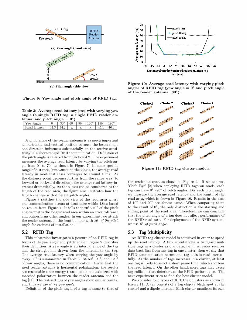
Figure 9: Yaw angle and pitch angle of RFID tag.
Table 3: Average read latency [ms] with varying yawangle (a single RFID tag, a single RFID reader an-tenna, and pitch angle = 0◦).
Yaw Angle 0◦ 30◦ 60◦ 90◦ 120◦ 150◦ 180◦
Read latency 44.3 44.2 x x x 45.1 46.9
A pitch angle of the reader antenna is as much importantas horizontal and vertical position because the beam shapeand direction influences substantially on the receive sensi-tivity in a short-ranged RFID communication. Definition ofthe pitch angle is referred from Section 4.2. The experimentmeasures the average read latency by varying the pitch an-gle from 0◦ to 70◦ as shown in Figure 7. In some specificrange of distance, 0cm∼30cm on the x-axis, the average readlatency in most test cases converges to around 13ms. Asthe distance point becomes further from the range area (toforward or backward direction), the average read latency in-creases dramatically. As the x-axis can be considered as thelength of the read area, the figure also illustrates how thelength changes with different pitch angles.
Figure 8 sketches the side view of the read area whereone communication occurs at least once within 18ms basedon results from Figure 7. It tells that 20◦∼40◦ of the pitchangles creates the longest read area within an error toleranceand outperforms other angles. In our experiment, we attachthe reader antenna on the front bumper with 30◦ of the pitchangle for easiness of installation.
5.2 RFID TagThis subsection investigates a posture of an RFID tag in
terms of its yaw angle and pitch angle. Figure 9 describestheir definition. A yaw angle is an internal angle of the tagand the straight line drawn from the antenna to the tag.The average read latency when varying the yaw angle byevery 30◦ is summarized in Table 3. At 60◦, 90◦, and 120◦
of yaw angles, there is no communication. Given that theused reader antenna is horizontal polarization, the resultsare reasonable since energy transmission is maximized withmatched polarization between the reader antenna and thetag [11]. The rest settings of yaw angles show similar results,and thus we use 0◦ of yaw angle.
Definition of the pitch angle of a tag is same to that of
Figure 10: Average read latency with varying pitchangles of RFID tag (yaw angle = 0◦ and pitch angleof the reader antenna=30◦).
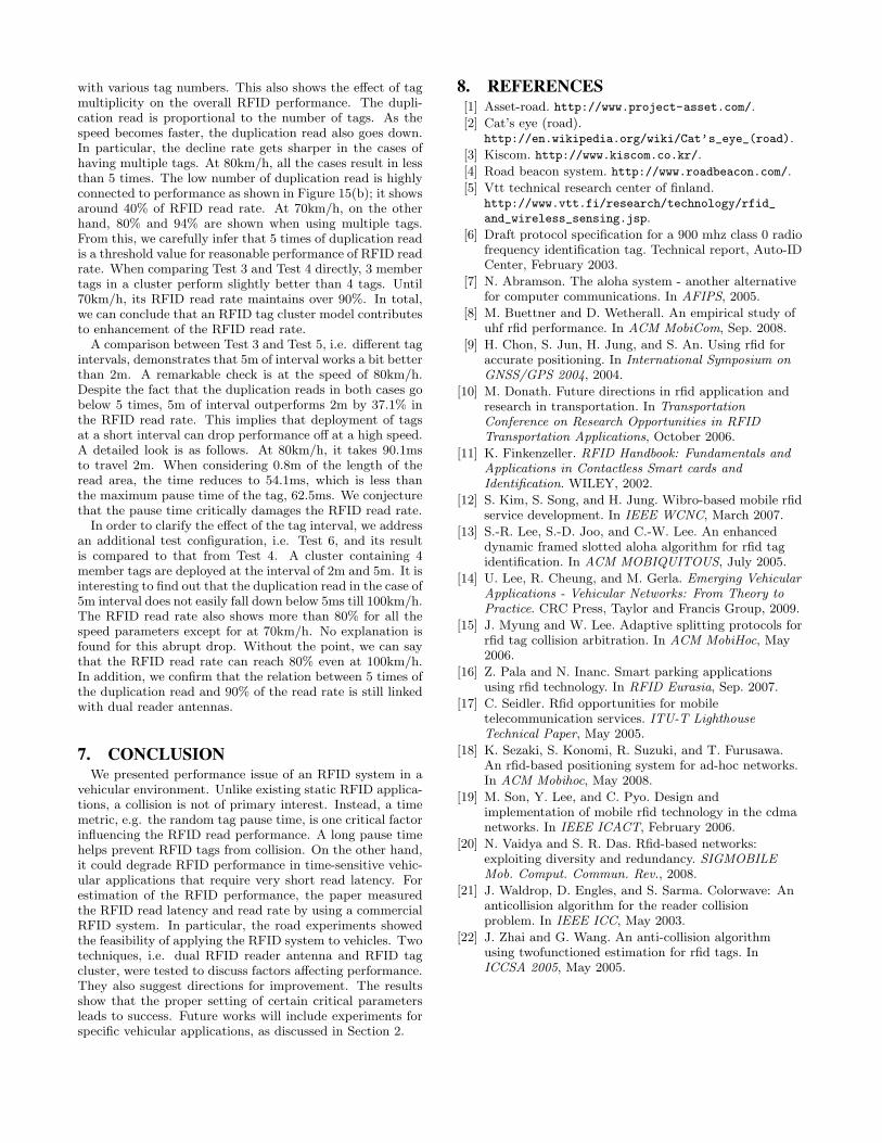
Figure 11: RFID tag cluster models.
the reader antenna as shown in Figure 9. If we can use’Cat’s Eye’ [2] when deploying RFID tags on roads, eachtag can have 0◦∼20◦ of pitch angles. For each pitch angle,we measure the average read latency and the length of theread area, which is shown in Figure 10. Results in the caseof 10◦ and 20◦ are almost same. When comparing themto the result of 0◦, the only distinction is the starting andending point of the read area. Therefore, we can concludethat the pitch angle of a tag does not affect performance ofthe RFID read rate. For deployment of the RFID system,we use 0◦ of pitch angle.
5.3 Tag MultiplicityAn RFID tag cluster model is contrived in order to speed
up the read latency. A fundamental idea is to regard mul-tiple tags in a cluster as one data, i.e. if a reader receivesdata back first from any tag in one cluster, then we say thatRFID communication occurs and tag data is read success-fully. As the number of tags increases in a cluster, at leastone tag is likely to select a short pause time, which shortensthe read latency. On the other hand, more tags may causetag collision that deteriorates the RFID performance. Thenext experiment tries to find the best cluster model.
We consider four types of RFID tag clusters as shown inFigure 11. A tag consists of a tag chip (a black spot at thecenter) and a dipole antenna. Each cluster manifests its own

Figure 12: Average read latency with four RFID tagcluster models.
characteristic in a way how to combine multiple tags in onecluster. Cluster 1 and 2 represent horizontal and vertical in-tegration, respectively. In the next, a space is given betweentwo neighboring member tags, which is expected to enhancethe receive sensitivity. In Cluster 4, the tag chips share onedipole antenna. We randomly place each cluster within thetarget read distance (0.5m) and compute an average readlatency after iterating the experiment.
Figure 12 shows the average read latency with four RFIDtag cluster models with increasing the number of the tagsfrom 1 to 5. At first, it verifies that as a cluster includes moretags the read latency comes to be shorter. In Cluster 2, 3,and 4, the time values go down below 18ms when there are 2,3, and 4 members tags. With 5 member tags, performancegets much worse due to tag collision. Based on results, wedecide to use Cluster 3 having 3 or 4 members of RFID tagssince they show the best performance.
5.4 Preliminary ResultWe have conducted laboratory experiments to study how
to install an RFID system on a road environment. Recallour target performance in Section 4.3, i.e. an RFID systemshould provide 0.5m of read distance in which communica-tion occurs within 18ms. Our laboratory experiments withstationary test sets quantify that the length of the read area(read distance) becomes 0.8m with 18ms of the read latency.The result allows us to calculate the maximum speed atwhich a vehicle can read RFID data while traveling as be-low. This estimation is also equivalent to the estimation inthe previous research [9].
velocity =0.8084
0.018= 44.9[m/s] = 161.7[Km/h]
6. EVALUATION OF RFID READ RATE ONTEST ROAD
In this section, we conduct road experiments in the realtestbed after installing the RFID system.
6.1 Testbed ConfigurationFigure 13 shows our testbed. Figure 13(a) displays a test
vehicle equipped with the RFID system. The RFID readerantenna is mounted on the front bumper, which is connectedto the location determination server via the reader. Theserver allows a user to monitor RFID data read by the an-tennas in real-time while driving. The tags are attached onthe surface of the test road. Figure 13(b) depicts the read
area. The test road is pictured in Figure 13(c). Note thatdue to safety issues, e.g. snow, there were some limitationson experiments such as the maximum speed of the test vehi-cle. Default parameters for both the reader antenna(s) andthe tags are denoted in Table 4, as discussed in the previ-ous sections. We conduct 6 tests by changing 4 variables asrepresented in Table 5.
In the experiments, we measure the average duplicationread and the average read rate. The average read rate repre-sents the overall performance of the RFID system, but can-not tell details. For this end, the average duplication read isused for a metric to assess the impact of the two proposedtechniques on the RFID performance. Due to inherent fea-ture of the RFID system, the reader is highly likely to obtainduplicated data from the same tag. Therefore, adding moretags in a cluster, i.e. tag multiplicity, would clearly increasethe duplication read in a static scenario or at a slow speed.As the speed gets faster, however, higher duplication readvalue due to multiple tags results in better performance. Wealso observed that there is a close relationship between two
Figure 13: Testbed: RFID system, a vehicle, and aroad.

Table 4: Parameters for deployment.Reader antenna value RFID tag value
Numbers 1 or 2 Yaw angle 0◦
Height 30cm Pitch angle 0◦
Pitch angle 30◦ Number of tagsin Cluster 3
1, 3, or 4
Table 5: Test scenarios with variables.Test1 Test2 Test3 Test4 Test5 Test6
Number of RFIDreader antenna
1 2 2 2 2 2
Number of RFIDtags in Cluster 3
1 1 3 4 3 4
Interval of neigh-boring RFID tags
2m 2m 2m 2m 5m 5m
Maximum speed[km/h]
∼100 ∼80 ∼80 ∼80 ∼80 ∼100
experiment metrics. By monitoring the duplication read val-ues, we can look at how the proposed techniques work withvarious speeds.
6.2 Effect of Antenna Diversity
Figure 14: Results from Test 1 and Test 2.
Test 1 is considered to evaluate the RFID read rate in thestraightforward configuration: a single reader antenna anda single tag. The tags are placed at 2m interval and the testvehicle travels at the maximum speed of 100km/h. The re-sult is compared to that from Test 2 to see the effect of dualRFID reader antennas, as summarized in Figure 14. Figure14(a) shows that the duplication read declines to less than 3times at the high speed. In the worst case, the decrease rategoes up to 78.6%, which explicitly reveals that the RFID sys-tem is prone to corruption with fast moving vehicles. Thisexpectation is verified from Figure 14(b). It shows that theread rate drops rapidly as the vehicle speeds up. But, after40km/h of speed, the read rate converges to 40∼50%. Onething to notice is that two measurements, i.e. the average
Figure 15: Experiments with dual RFID reader an-tenna (Test 2 to Test 6).
duplication read and the average read rate are tightly cou-pled. In the next subsection, we will look at how the tagcluster model affects the interconnection. When comparingtwo RFID reader antenna(s), we could not find a huge differ-ence in the results. This is mostly because the test vehicletravels along the center of the lane for the sake of safety.But, as shown in Figure 6, the dual reader antenna widensthe read area, decreasing probability that the reader missesthe tags. Adding one more reader antenna cuts down thelength of the read area, but the result discloses that it doesnot have an effect on performance. If we consider antennamultiplicity, i.e. assuming to install additional antennas inthe rear bumper, it can increase the length and affect theRFID read performance favorably.
6.3 Effect of Tag MultiplicityWith dual RFID reader antennas, we vary the number of
member tags in Cluster 3 and the interval, i.e. Test 2 toTest 6. The results are shown in Figure 15.
In Test 2, 3, and 4, there are different numbers of mem-ber tags in Cluster 3 at a 2m tag interval. In particular, theconfiguration of Test 2 is equivalent to using a single tag,i.e. a primitive tag setting of the commercial RFID system.Therefore, the results immediately compare the performance
with various tag numbers. This also shows the effect of tagmultiplicity on the overall RFID performance. The dupli-cation read is proportional to the number of tags. As thespeed becomes faster, the duplication read also goes down.In particular, the decline rate gets sharper in the cases ofhaving multiple tags. At 80km/h, all the cases result in lessthan 5 times. The low number of duplication read is highlyconnected to performance as shown in Figure 15(b); it showsaround 40% of RFID read rate. At 70km/h, on the otherhand, 80% and 94% are shown when using multiple tags.From this, we carefully infer that 5 times of duplication readis a threshold value for reasonable performance of RFID readrate. When comparing Test 3 and Test 4 directly, 3 membertags in a cluster perform slightly better than 4 tags. Until70km/h, its RFID read rate maintains over 90%. In total,we can conclude that an RFID tag cluster model contributesto enhancement of the RFID read rate.
A comparison between Test 3 and Test 5, i.e. different tagintervals, demonstrates that 5m of interval works a bit betterthan 2m. A remarkable check is at the speed of 80km/h.Despite the fact that the duplication reads in both cases gobelow 5 times, 5m of interval outperforms 2m by 37.1% inthe RFID read rate. This implies that deployment of tagsat a short interval can drop performance off at a high speed.A detailed look is as follows. At 80km/h, it takes 90.1msto travel 2m. When considering 0.8m of the length of theread area, the time reduces to 54.1ms, which is less thanthe maximum pause time of the tag, 62.5ms. We conjecturethat the pause time critically damages the RFID read rate.
In order to clarify the effect of the tag interval, we addressan additional test configuration, i.e. Test 6, and its resultis compared to that from Test 4. A cluster containing 4member tags are deployed at the interval of 2m and 5m. It isinteresting to find out that the duplication read in the case of5m interval does not easily fall down below 5ms till 100km/h.The RFID read rate also shows more than 80% for all thespeed parameters except for at 70km/h. No explanation isfound for this abrupt drop. Without the point, we can saythat the RFID read rate can reach 80% even at 100km/h.In addition, we confirm that the relation between 5 times ofthe duplication read and 90% of the read rate is still linkedwith dual reader antennas.
7. CONCLUSIONWe presented performance issue of an RFID system in a
vehicular environment. Unlike existing static RFID applica-tions, a collision is not of primary interest. Instead, a timemetric, e.g. the random tag pause time, is one critical factorinfluencing the RFID read performance. A long pause timehelps prevent RFID tags from collision. On the other hand,it could degrade RFID performance in time-sensitive vehic-ular applications that require very short read latency. Forestimation of the RFID performance, the paper measuredthe RFID read latency and read rate by using a commercialRFID system. In particular, the road experiments showedthe feasibility of applying the RFID system to vehicles. Twotechniques, i.e. dual RFID reader antenna and RFID tagcluster, were tested to discuss factors affecting performance.They also suggest directions for improvement. The resultsshow that the proper setting of certain critical parametersleads to success. Future works will include experiments forspecific vehicular applications, as discussed in Section 2.
8. REFERENCES[1] Asset-road. http://www.project-asset.com/.
[2] Cat’s eye (road).http://en.wikipedia.org/wiki/Cat’s_eye_(road).
[3] Kiscom. http://www.kiscom.co.kr/.
[4] Road beacon system. http://www.roadbeacon.com/.
[5] Vtt technical research center of finland.http://www.vtt.fi/research/technology/rfid_
and_wireless_sensing.jsp.
[6] Draft protocol specification for a 900 mhz class 0 radiofrequency identification tag. Technical report, Auto-IDCenter, February 2003.
[7] N. Abramson. The aloha system - another alternativefor computer communications. In AFIPS, 2005.
[8] M. Buettner and D. Wetherall. An empirical study ofuhf rfid performance. In ACM MobiCom, Sep. 2008.
[9] H. Chon, S. Jun, H. Jung, and S. An. Using rfid foraccurate positioning. In International Symposium onGNSS/GPS 2004, 2004.
[10] M. Donath. Future directions in rfid application andresearch in transportation. In TransportationConference on Research Opportunities in RFIDTransportation Applications, October 2006.
[11] K. Finkenzeller. RFID Handbook: Fundamentals andApplications in Contactless Smart cards andIdentification. WILEY, 2002.
[12] S. Kim, S. Song, and H. Jung. Wibro-based mobile rfidservice development. In IEEE WCNC, March 2007.
[13] S.-R. Lee, S.-D. Joo, and C.-W. Lee. An enhanceddynamic framed slotted aloha algorithm for rfid tagidentification. In ACM MOBIQUITOUS, July 2005.
[14] U. Lee, R. Cheung, and M. Gerla. Emerging VehicularApplications - Vehicular Networks: From Theory toPractice. CRC Press, Taylor and Francis Group, 2009.
[15] J. Myung and W. Lee. Adaptive splitting protocols forrfid tag collision arbitration. In ACM MobiHoc, May2006.
[16] Z. Pala and N. Inanc. Smart parking applicationsusing rfid technology. In RFID Eurasia, Sep. 2007.
[17] C. Seidler. Rfid opportunities for mobiletelecommunication services. ITU-T LighthouseTechnical Paper, May 2005.
[18] K. Sezaki, S. Konomi, R. Suzuki, and T. Furusawa.An rfid-based positioning system for ad-hoc networks.In ACM Mobihoc, May 2008.
[19] M. Son, Y. Lee, and C. Pyo. Design andimplementation of mobile rfid technology in the cdmanetworks. In IEEE ICACT, February 2006.
[20] N. Vaidya and S. R. Das. Rfid-based networks:exploiting diversity and redundancy. SIGMOBILEMob. Comput. Commun. Rev., 2008.
[21] J. Waldrop, D. Engles, and S. Sarma. Colorwave: Ananticollision algorithm for the reader collisionproblem. In IEEE ICC, May 2003.
[22] J. Zhai and G. Wang. An anti-collision algorithmusing twofunctioned estimation for rfid tags. InICCSA 2005, May 2005.