Installation & Maintenance - Home - Continental Fan
8
Installation & Maintenance TF200 BATHROOM FANS VENTILADORES PARA BAÑOS Instalación & Mantenimiento READ AND SAVE THESE INSTRUCTIONS FOR FUTURE REFERENCE LEA Y GUARDE ESTAS INSTRUCCIONES PARA REFERENCIAS FUTURAS
Transcript of Installation & Maintenance - Home - Continental Fan

Installation & Maintenance
TF200 BATHROOM FANS
VENTILADORES PARA BAÑOS
Instalación & Mantenimiento
READ AND SAVE THESE INSTRUCTIONS FOR FUTURE REFERENCELEA Y GUARDE ESTAS INSTRUCCIONES PARA REFERENCIAS FUTURAS

SAFETY INSTRUCTIONS
TF200 fan is not explosion proof and should not be used when a potentiallyexplosive situation exists.
1. Ensure that the electrical service to the fan is locked in the “OFF” position. Do not re-establishpower supply until fan and activation device are completely installed.
2. Not suitable for use in cooking areas.3. This unit has rotating parts! Safety precautions must be exercised during installation, operation
and maintenance. Turn impeller by hand to make sure it rotates freely. 4. For general ventilation use only. Do not use to exhaust hazardous or explosive materials
and vapors. 5. To reduce the risk of fire, electric shock, or injury to persons — observe the following: a. Use this unit only in the manner intended by the manufacturer. If you have questions, contact
the factory. b. A qualified person(s) must perform installation work and electrical wiring in accordance
with all applicable codes and standards, including fire-rated construction. c. The combustion airflow needed for safe operation of fuel burning equipment may be
affected by this unit’s operation. Follow the heating equipment manufacturer’s guidelinesand safety standards as published by the National Fire Protection Association (NFPA), theAmerican Society of Heating, Refrigeration, and Air Conditioning Engineers (ASHRAE), andlocal code authorities.
d. When cutting or drilling into walls or ceilings, take care not to damage electrical wires orother hidden utilities.
e. Ducted fans must always be vented to the outdoors when used to exhaust moist/humid air.6. Check voltage at the fan to see that it corresponds to the motor nameplate.7. TF fans are suitable for installation over a shower or tub when installed in a GFCI (Ground Fault
Circuit Interrupter) protected branch circuit. This unit must be grounded.8. The fan must not be installed in a ceiling that is thermally insulated to a value greater than R40.9. If fan is mounted at an angle, duct connector must point up.
To reduce the risk of fire or electric shock, do not use this fan with any solid-state speed control device.
TF200 BATHROOm FAN
The delivery set includes:
• Fan• Grille • Hanger Bracket (4)• Hardware Kit for Hanger Bracket:
Screw A (8) Screw B (6) Washer (8)
Vibration Isolator 1 (4) Vibration Isolator 2 (4) Vibration Isolator 3 (4)
NOTICE
2
WARNING

VibrationIsolator 1 Washer
Washer
VibrationIsolator 2
Vibration Isolator 3Screw A
Joist
Screw B
Figure 2Figure 1
Figure 4Figure 3
3
FAN INSTALLATION
Disconnect and lock out power supply before performing any installation work.Working on or near energized equipment could result in death or serious injury.
STEP 1. INSTALL HOUSING (A or B)A) Hanger Brackets
Hanger brackets allow the fan to be suspended when a mounting surface is not available.Assemble vibration isolator 3 and hanger bracket to the housing using screw A. Install vibrationisolators 1 and 2 to the hanger bracket. Use the washers provided and anchor bolt (notincluded) to secure the housing (Figure 1).
B) Fasten to Joist Position the housing so the bottom edge is flush with the finished ceiling. Secure with screws(Figure 2). If necessary, construct a frame around the flange of the housing to provide additionalsupport.
STEP 3. INSTALL DUCT CONNECTOR & DUCTUsing the recommended duct size, connect duct to the damper/duct connector (Figure 3), andrun duct to an exterior roof or wall cap using the shortest, straightest duct routing possible.Ensure all duct connections are airtight.
STEP 4. CONNECT WIRINGRefer to wiring diagram on page 4. Reattach all electrical box covers before applying power.
STEP 5. INSTALL GRILLE Pinch the springs on the sides of grille and insert them into the slots in the housing. Firmlypush the grille against the ceiling to secure (Figure 4).
WARNING
TROUBLESHOOTING
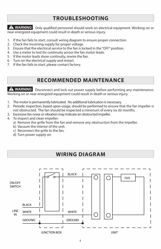
Only qualified personnel should work on electrical equipment. Working on ornear energized equipment could result in death or serious injury.
1. If the fan fails to start, consult wiring diagram to ensure proper connection. 2. Check the incoming supply for proper voltage. 3. Ensure that the electrical service to the fan is locked in the “OFF” position.4. Use a meter to test for continuity across the fan motor leads. 5. If the motor leads show continuity, rewire the fan. 6. Turn on the electrical supply and restart. 7. If the fan fails to start, please contact factory.
RECOmmENDED mAINTENANCE
Disconnect and lock out power supply before performing any maintenance.Working on or near energized equipment could result in death or serious injury.
1. The motor is permanently lubricated. No additional lubrication is necessary.2. Periodic inspection, based upon usage, should be performed to ensure that the fan impeller is
not obstructed. The fan should be inspected a minimum of every six (6) months. 3. Excessive fan noise or vibration may indicate an obstructed impeller.4. To inspect and clean impeller: a) Remove the grille from the fan and remove any obstruction from the impeller. b) Vacuum the interior of the unit. c) Reconnect the grille to the fan. d) Turn power supply on.
WIRING DIAGRAm
WARNING
WARNING
FANON/OFFSWITCH
JUNCTION BOX UNIT
WHITEWHITE
GROUNDGROUND
BLACK
BLACK
LINEIN
4
INSTRUCCIONES DE SEGURIDAD
Los ventiladores TF no están hechos a prueba de explosiones, y no deben usarseen situaciones donde haya riesgo de explosión.
1. Asegúrese que el suministro eléctrico del ventilador esté bloqueado en la posición “OFF”. Norestablezca el suministro de energía hasta que el ventilador y el dispositivo de activación esténcompletamente instalados.
2. Los ventiladores TF no son apropiados para usos en áreas de cocina. 3. ¡Esta unidad tiene partes giratorias! Se deben tomar precauciones de seguridad durante la in-
stalación, la operación, y el mantenimiento. Gire el propulsor manualmente para asegurarsede que gire libremente.
4. Únicamente para usos de ventilación general. No lo utilice para extraer materiales y vaporespeligrosos o explosivos.
5. Tome en cuenta lo siguiente para reducir el riesgo de incendio, descarga eléctrica, o lesionesa personas:
a. Utilice esta unidad solo de la manera prevista por el fabricante. Si tiene preguntas, contacteal fabricante.
b. Sólo personas calificadas deben realizar los trabajos de instalación y cableado eléctrico,siguiendo todos los códigos y normas aplicables, incluyendo los de construcción a pruebade incendios.
c. El funcionamiento de esta unidad puede afectar el flujo de aire de combustión que se nece-sita para la operación segura de equipo que queme combustible. Siga las normas del fab-ricante y los estándares de seguridad para equipo de calefacción, según lo establecen laAsociación Estadounidense de Protección Contra Incendios (NFPA), la Sociedad Americanade Ingenieros en Calefacción, Refrigeración y Aire Acondicionado (ASHRAE), y las agenciasnormativas locales.
d. Al cortar o taladrar paredes o techos, tenga cuidado de no dañar los cables eléctricos u otrosservicios ocultos.
e. Los ventiladores con ductos siempre deben tener salida al exterior cuando se usan para ex-traer aire húmedo.
6. Revise el voltaje del ventilador para ver si corresponde con el de la placa del motor. 7. Los ventiladores TF son adecuados para montar sobre una ducha o bañera cuando están in-
stalados en un ramal del circuito protegido por un interruptor de seguridad GFCI (falla deconexión a tierra). Esta unidad debe estar aterrizada.
8. El ventilador no debe instalarse en un techo que esté térmicamente aislado a más de R40. 9. Si el ventilador está montado en ángulo, el conector del ducto debe apuntar hacia arriba.
Para reducir el riesgo de incendio o descarga eléctrica, no utilice este ventiladorcon ningún dispositivo de control de velocidad de estado sólido.
VENTILADORES TF200 PARA BAñOS
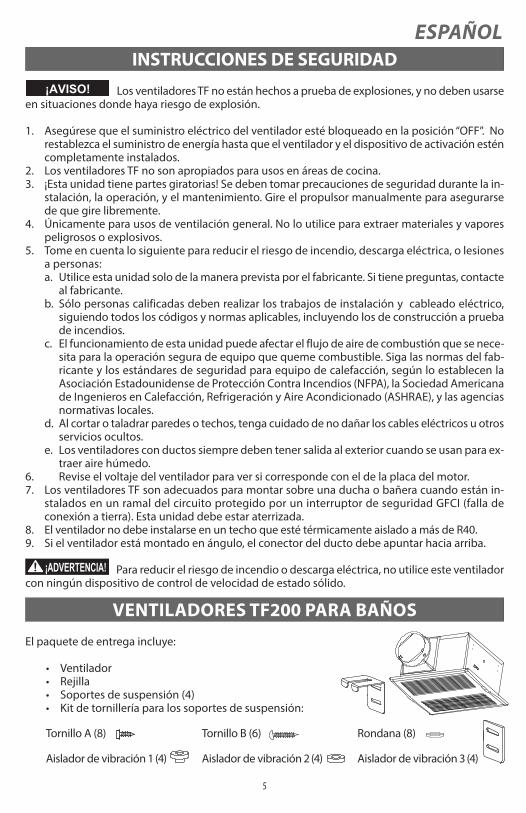
El paquete de entrega incluye:
• Ventilador• Rejilla • Soportes de suspensión (4)• Kit de tornillería para los soportes de suspensión:
Tornillo A (8) Tornillo B (6) Rondana (8)
Aislador de vibración 1 (4) Aislador de vibración 2 (4) Aislador de vibración 3 (4)
¡AVISO!
5
¡ADVERTENCIA!
ESPAÑOL
Aislador de vibración 1 Rondana
Rondana
Aislador devibración 2
Aislador devibración 3Tornillo A
Vigueta
Tornillo B
Fig. 2Fig. 1
Fig. 4Fig. 3
6
INSTALACIÓN DEL VENTILADOR
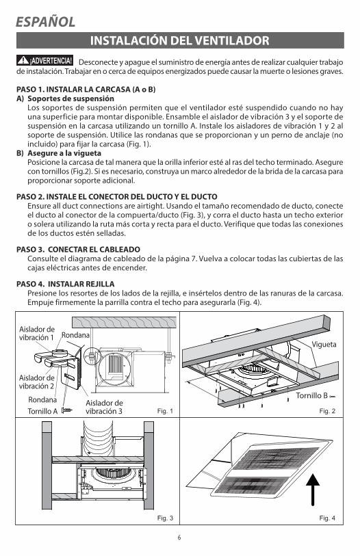
Desconecte y apague el suministro de energía antes de realizar cualquier trabajode instalación. Trabajar en o cerca de equipos energizados puede causar la muerte o lesiones graves.
PASO 1. INSTALAR LA CARCASA (A o B)A) Soportes de suspensión
Los soportes de suspensión permiten que el ventilador esté suspendido cuando no hayuna superficie para montar disponible. Ensamble el aislador de vibración 3 y el soporte desuspensión en la carcasa utilizando un tornillo A. Instale los aisladores de vibración 1 y 2 alsoporte de suspensión. Utilice las rondanas que se proporcionan y un perno de anclaje (noincluido) para fijar la carcasa (Fig. 1).
B) Asegure a la viguetaPosicione la carcasa de tal manera que la orilla inferior esté al ras del techo terminado. Asegurecon tornillos (Fig.2). Si es necesario, construya un marco alrededor de la brida de la carcasa paraproporcionar soporte adicional.
PASO 2. INSTALE EL CONECTOR DEL DUCTO Y EL DUCTOEnsure all duct connections are airtight. Usando el tamaño recomendado de ducto, conecteel ducto al conector de la compuerta/ducto (Fig. 3), y corra el ducto hasta un techo exterioro solera utilizando la ruta más corta y recta para el ducto. Verifique que todas las conexionesde los ductos estén selladas.
PASO 3. CONECTAR EL CABLEADO Consulte el diagrama de cableado de la página 7. Vuelva a colocar todas las cubiertas de lascajas eléctricas antes de encender.
PASO 4. INSTALAR REJILLA Presione los resortes de los lados de la rejilla, e insértelos dentro de las ranuras de la carcasa.Empuje firmemente la parrilla contra el techo para asegurarla (Fig. 4).
¡ADVERTENCIA!
ESPAÑOL

VENTILADOR
CAJA DE CONEXIONES UNIDAD
BLANCOBLANCO
TIERRATIERRA
NEGRO
NEGRO
CONECTOR DE ENTRADA
INTERRUPOR DE ENCENDIDO
Y APAGADO
SOLUCIÓN DE PROBLEmAS
Solo personal calificado debe trabajar con equipo eléctrico. Trabajar en o cercade equipo energizado podría causar la muerte o lesiones graves.
1. Si el ventilador no se enciende, consulte el diagrama de cableado para asegurarse de que estáconectado correctamente.
2. Revise que la electricidad entrante tenga el voltaje apropiado.3. Asegúrese que el servicio eléctrico al ventilador esté bloqueado en la posición de apagado (OFF).4. Use un medidor para probar el flujo de corriente a través de las conexiones del motor del
ventilador.5. Si los cables al motor muestran continuidad, revise el cableado.6. Active el suministro eléctrico y vuelva a encender. 7. Si el ventilador no enciende, por favor contacte al fabricante.
mANTENImIENTO RECOmENDADO
Desconecte y bloquee el suministro de energía antes de llevar a cabo cualquiermantenimiento. Trabajar en o cerca de equipo energizado puede causar la muerte o lesiones serias.
1. El motor está permanentemente lubricado. No se requiere lubricación adicional.2. Se debe hacer una inspección periódica, dependiendo del uso, para asegurar que el propulsor
del ventilador no esté obstruido. Se debe inspeccionar el ventilador al menos cada seis (6) meses. 3. El ruido o vibración excesiva del ventilador puede indicar que el propulsor está obstruido. 4. Para inspeccionar y limpiar el propulsor: a) Quite la rejilla del ventilador, y elimine cualquier obstrucción del propulsor. b) Aspire el interior de la unidad. c) Vuelva a colocar la rejilla en el ventilador. d) Encienda el suministro de energía.
DIAGRAmA DE CABLEADO
¡ADVERTENCIA!
¡ADVERTENCIA!
7
ESPAÑOL

TF200 FAN-I&M-1810
1-800-779-4021 • www.continentalfan.com
Continental Fan Manufacturing Inc.203 Eggert Road
Bu�alo, New York 14215
Continental Fan Manufacturing Inc.6274 Executive Blvd.Dayton, Ohio 45424
Continental Fan Canada Inc.12-205 Matheson Blvd E
Mississauga, Ontario L4Z 3E3
ACCEPTANCE CERTIFICATECERTIFICADO DE ACEPTACIÓN
CONNECTION CERTIFICATE CERTIFICADO DE CONEXIÓN
The TF fan has been duly certified as serviceable.El ventilador TF está debidamente certificado como apto para ser usado.
TF200
Manufactured on (date) /Fabricado el (fecha):
Date of sale / Fecha de venta:
Sold by / Vendido por:(name of trading enterprise, stamp of store / nombre de empresa mercantil, sello de la tienda)
Company name / Nombre de la empresa:
Electrician name / Nombre del electricista:
Date / Fecha:
Signature / Firma:
Due to constant product improvements, some models may differ slightly from those portrayed in this manual. Debido a las constantes mejoras del producto, algunos modelos pueden variar levemente de los que se presentan en estemanual.