Installation 06CC Instructions Compound Cooling … · Failure to follow these instructions will...
8
GENERAL 1. Inspect compressor for shipping damage and file claim with shipping company if damaged or incomplete. 2. Check compressor nameplate for correct model and voltage designation. 3. Before installation, review all Carlyle compressor appli- cation literature to assure yourself that the proper com- pressor has been selected and is being applied in a proper manner. The required application literature is available through Carlyle. SAFETY INSTRUCTIONS Only qualified, authorized, and appropriately trained HVAC or refrigeration personnel, should install, commission, and maintain this equipment. Use appropriate personal safety equipment where required. Safety goggles, gloves, protective clothing, safety boots, and hard hats should be worn where necessary. OPERATING LIMITS: Refer To Application Guide GENERAL INSTALLATION PROCEDURES Holding Charge Compressor is factory supplied with a 7 to 20 lb (0.5 to 1.4 bar) charge of dry air or nitrogen. This internal pressure must be relieved before attempting to remove any compres- sor fitting or part. Relieve holding charge by removing the cap on the inter- stage connection fitting and depressing the internal disc. See Fig. 1A for applicable interstage pressure connection fit- ting location. Service Valves Remove valve pads and attach factory-supplied suction and discharge gaskets and service valves to the compressor. Torque 5 / 16 -in. -18 mounting bolts 20 to 25 lb-ft (27 to 34 Nm) and 1 / 2 -in. -13 mounting bolts 80 to 90 lb-ft (109 to 122 Nm). When brazing piping to valve, wrap the valve in a wet cloth to prevent heat damage. Oil 1. Check to see that oil level is 1 / 4 to 3 / 4 of the way up on compressor sight glass before starting and after 15 to 20 minutes of operation. Compressors may be shipped with or without an oil charge based on model. All com- pressors must contain the specified oil charge prior to start-up as a condition of warranty. 2. To add oil: Relieve internal crankcase pressure, isolate crankcase, and add oil through the oil fill connection (see Fig. 1A and 1B). To remove excess oil: Reduce in- ternal crankcase pressure to 2 psig (1.15 bar), isolate crankcase, then loosen the oil drain plug allowing oil to seep out past the threads of the plug. 3. When additional oil or a complete oil change is re- quired, use only the listed Carlyle approved oils. Manufacturer Brand Name Totaline 150 Witco Suniso 3GS IGI Petroleum Ind. Cryol-150 DANGER Failure to follow these instructions will result in severe personal injury or death. ELECTRIC SHOCK HAZARD. Do not operate compres- sor or provide electric power to it unless the compressor terminal box is installed and the terminal box cover is in place and secured. DO NOT provide power to unit or turn on compressor un- less suction and discharge service valves are open. DO NOT remove the compressor terminal box cover until all electrical sources have been disconnected. DO NOT USE oxygen or other industrial gases for tight- ness/pressure testing. Use nitrogen or inert gas. WARNING Failure to follow these instructions may result in serious injury or death. CONTENTS UNDER PRESSURE. Compressor con- tains oil and refrigerant under pressure. Pressure must be relieved before installation, servicing or opening any connections. HOT and COLD surface temperatures can occur during operation and can result in severe burns or frostbite. USE ONLY approved refrigerants and refrigeration oils. NEVER EXCEED specified test pressures. System strength/tightness test pressure may not exceed the compressor maximum Test pressure on the Nameplate. Close shutoff valves to isolate compressor if necessary. CHECK THE REFRIGERANT TYPE. Charge only with refrigerant that conforms to AHRI Standard 700. CAUTION With the compressor crankcase under slight pressure, do not remove the oil drain plug as the entire oil charge could be lost. Do not reuse drained oil or oil that has been exposed to the atmosphere. CAUTION Do not charge oil through the suction line or through the compressor suction access fittings. See Fig. 1A for the recommended oil charging port. Adding oil into the suc- tion side of the compressor can cause damage to the suction/discharge valves, pistons, and/or connecting rods. Installation Instructions 06CC Compound Cooling Compressor
Transcript of Installation 06CC Instructions Compound Cooling … · Failure to follow these instructions will...
GENERAL1. Inspect compressor for shipping damage and file claim
with shipping company if damaged or incomplete.2. Check compressor nameplate for correct model and
voltage designation.3. Before installation, review all Carlyle compressor appli-
cation literature to assure yourself that the proper com-pressor has been selected and is being applied in aproper manner. The required application literature isavailable through Carlyle.
SAFETY INSTRUCTIONS
Only qualified, authorized, and appropriately trained HVACor refrigeration personnel, should install, commission, andmaintain this equipment.Use appropriate personal safety equipment where required.Safety goggles, gloves, protective clothing, safety boots, andhard hats should be worn where necessary.
OPERATING LIMITS: Refer To ApplicationGuide
GENERAL INSTALLATION PROCEDURES
Holding ChargeCompressor is factory supplied with a 7 to 20 lb (0.5 to1.4 bar) charge of dry air or nitrogen. This internal pressuremust be relieved before attempting to remove any compres-sor fitting or part.Relieve holding charge by removing the cap on the inter-stage connection fitting and depressing the internal disc.See Fig. 1A for applicable interstage pressure connection fit-ting location.
Service ValvesRemove valve pads and attach factory-supplied suction anddischarge gaskets and service valves to the compressor.Torque 5/16-in. -18 mounting bolts 20 to 25 lb-ft (27 to34 Nm) and 1/2-in. -13 mounting bolts 80 to 90 lb-ft (109 to122 Nm). When brazing piping to valve, wrap the valve in awet cloth to prevent heat damage.
Oil1. Check to see that oil level is 1/4 to 3/4 of the way up on
compressor sight glass before starting and after 15 to20 minutes of operation. Compressors may be shippedwith or without an oil charge based on model. All com-pressors must contain the specified oil charge prior tostart-up as a condition of warranty.
2. To add oil: Relieve internal crankcase pressure, isolatecrankcase, and add oil through the oil fill connection(see Fig. 1A and 1B). To remove excess oil: Reduce in-ternal crankcase pressure to 2 psig (1.15 bar), isolatecrankcase, then loosen the oil drain plug allowing oil toseep out past the threads of the plug.
3. When additional oil or a complete oil change is re-quired, use only the listed Carlyle approved oils.
Manufacturer Brand NameTotaline 150Witco Suniso 3GSIGI Petroleum Ind. Cryol-150
DANGER
Failure to follow these instructions will result in severepersonal injury or death.ELECTRIC SHOCK HAZARD. Do not operate compres-sor or provide electric power to it unless the compressorterminal box is installed and the terminal box cover is inplace and secured.DO NOT provide power to unit or turn on compressor un-less suction and discharge service valves are open.DO NOT remove the compressor terminal box cover untilall electrical sources have been disconnected.DO NOT USE oxygen or other industrial gases for tight-ness/pressure testing. Use nitrogen or inert gas.
WARNING
Failure to follow these instructions may result in seriousinjury or death.CONTENTS UNDER PRESSURE. Compressor con-tains oil and refrigerant under pressure. Pressure mustbe relieved before installation, servicing or opening anyconnections.HOT and COLD surface temperatures can occur duringoperation and can result in severe burns or frostbite.USE ONLY approved refrigerants and refrigeration oils.NEVER EXCEED specified test pressures. Systemstrength/tightness test pressure may not exceed thecompressor maximum Test pressure on the Nameplate.Close shutoff valves to isolate compressor if necessary.CHECK THE REFRIGERANT TYPE. Charge only withrefrigerant that conforms to AHRI Standard 700.
CAUTION
With the compressor crankcase under slight pressure, donot remove the oil drain plug as the entire oil chargecould be lost. Do not reuse drained oil or oil that hasbeen exposed to the atmosphere.
CAUTION
Do not charge oil through the suction line or through thecompressor suction access fittings. See Fig. 1A for therecommended oil charging port. Adding oil into the suc-tion side of the compressor can cause damage to thesuction/discharge valves, pistons, and/or connectingrods.
InstallationInstructions
06CCCompound Cooling
Compressor
2
ELECTRICAL
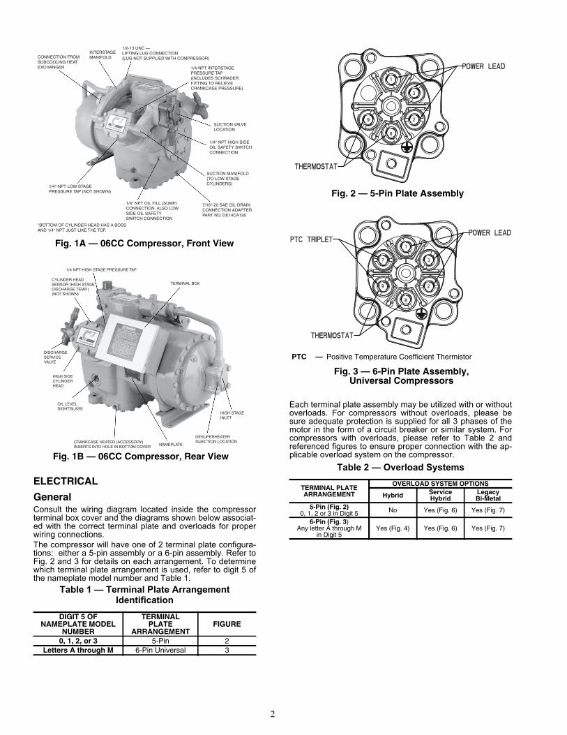
GeneralConsult the wiring diagram located inside the compressorterminal box cover and the diagrams shown below associat-ed with the correct terminal plate and overloads for properwiring connections.The compressor will have one of 2 terminal plate configura-tions: either a 5-pin assembly or a 6-pin assembly. Refer toFig. 2 and 3 for details on each arrangement. To determinewhich terminal plate arrangement is used, refer to digit 5 ofthe nameplate model number and Table 1.
Table 1 — Terminal Plate Arrangement Identification
Each terminal plate assembly may be utilized with or withoutoverloads. For compressors without overloads, please besure adequate protection is supplied for all 3 phases of themotor in the form of a circuit breaker or similar system. Forcompressors with overloads, please refer to Table 2 andreferenced figures to ensure proper connection with the ap-plicable overload system on the compressor.
Table 2 — Overload Systems
DIGIT 5 OFNAMEPLATE MODEL
NUMBER
TERMINALPLATE
ARRANGEMENTFIGURE
0, 1, 2, or 3 5-Pin 2Letters A through M 6-Pin Universal 3
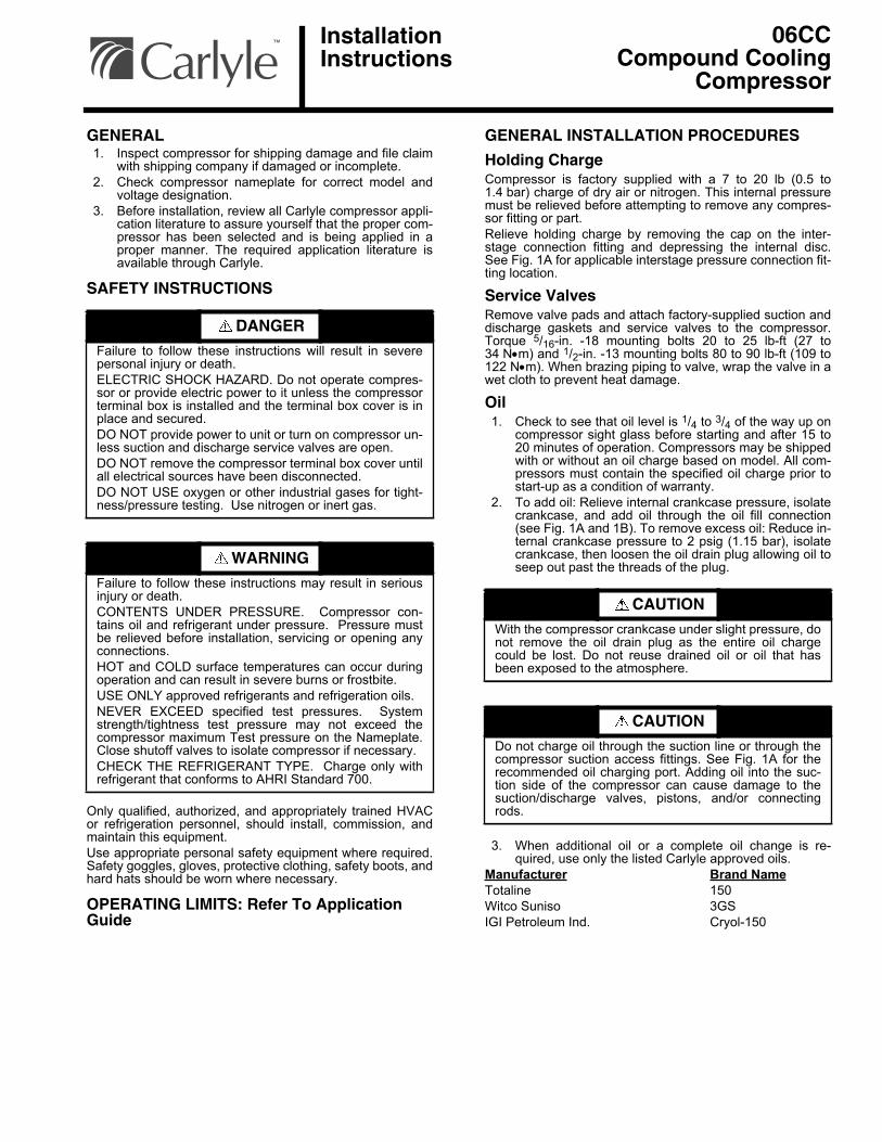
Fig. 1A — 06CC Compressor, Front View
INTERSTAGE MANIFOLD
1/2-13 UNC —LIFTING LUG CONNECTION(LUG NOT SUPPLIED WITH COMPRESSOR)
1/4-NPT INTERSTAGE PRESSURE TAP (INCLUDES SCHRADER FITTING TO RELIEVE CRANKCASE PRESSURE)
SUCTION VALVE LOCATION
1/4” NPT HIGH SIDE OIL SAFETY SWITCH CONNECTION
SUCTION MANIFOLD (TO LOW STAGE CYLINDERS)
7/16”-20 SAE OIL DRAIN CONNECTION ADAPTER PART NO. DE14CA126
1/4” NPT OIL FILL (SUMP) CONNECTION. ALSO LOW SIDE OIL SAFETY SWITCH CONNECTION
*BOTTOM OF CYLINDER HEAD HAS A BOSS AND 1/4” NPT JUST LIKE THE TOP.
1/4”-NPT LOW STAGE PRESSURE TAP (NOT SHOWN)
CONNECTION FROM SUBCOOLING HEAT EXCHANGER
Fig. 1B — 06CC Compressor, Rear View
1/4 NPT HIGH STAGE PRESSURE TAP
TERMINAL BOXCYLINDER HEAD SENSOR (HIGH STAGE DISCHARGE TEMP.) (NOT SHOWN)
DISCHARGE SERVICE VALVE
HIGH SIDE CYLINDER HEAD
OIL LEVEL SIGHTGLASS
CRANKCASE HEATER (ACCESSORY) INSERTS INTO HOLE IN BOTTOM COVER NAMEPLATE
DESUPERHEATER INJECTION LOCATION
HIGH STAGE INLET
TERMINAL PLATEARRANGEMENT
OVERLOAD SYSTEM OPTIONS
Hybrid ServiceHybrid
LegacyBi-Metal
5-Pin (Fig. 2)0, 1, 2 or 3 in Digit 5 No Yes (Fig. 6) Yes (Fig. 7)
6-Pin (Fig. 3)Any letter A through M
in Digit 5Yes (Fig. 4) Yes (Fig. 6) Yes (Fig. 7)
Fig. 2 — 5-Pin Plate Assembly
Fig. 3 — 6-Pin Plate Assembly,Universal Compressors
PTC — Positive Temperature Coefficient Thermistor
3
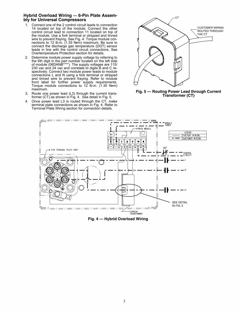
Hybrid Overload Wiring — 6-Pin Plate Assem-bly for Universal Compressors1. Connect one of the 2 control circuit leads to connection
14 located on top of the module. Connect the othercontrol circuit lead to connection 11 located on top ofthe module. Use a fork terminal or stripped and tinnedwire to prevent fraying. See Fig. 4. Torque module con-nections to 12 lb-in. (1.35 Nm) maximum. Be sure toconnect the discharge gas temperature (DGT) sensorleads in line with the control circuit connections. SeeOvertemperature Protection section for details.
2. Determine module power supply voltage by referring tothe 6th digit in the part number located on the left sideof module (06DANB****). The supply voltages are 115/230 vac and 24 vac and correlate to digits B and C re-spectively. Connect two module power leads to moduleconnections L and N using a fork terminal or strippedand tinned wire to prevent fraying. Refer to modulefront label for further power supply requirements.Torque module connections to 12 lb-in. (1.35 Nm)maximum.
3. Route one power lead (L3) through the current trans-former (CT) as shown in Fig. 4. See detail in Fig. 5.
4. Once power lead L3 is routed through the CT, maketerminal plate connections as shown in Fig. 4. Refer toTerminal Plate Wiring section for connection details.
Fig. 5 — Routing Power Lead through CurrentTransformer (CT)
CT
CUSTOMER WIRINGROUTED THROUGHTHE CT
Fig. 4 — Hybrid Overload Wiring
SEE DETAIL IN FIG. 5
4
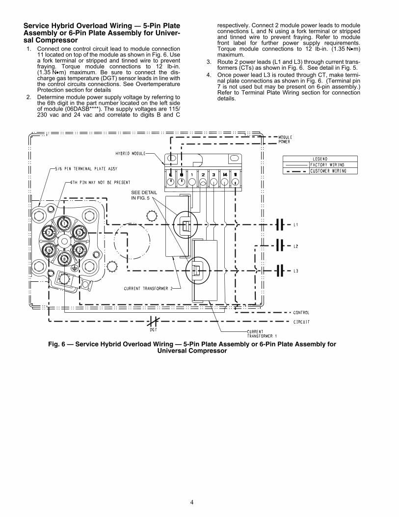
Service Hybrid Overload Wiring — 5-Pin PlateAssembly or 6-Pin Plate Assembly for Univer-sal Compressor1. Connect one control circuit lead to module connection
11 located on top of the module as shown in Fig. 6. Usea fork terminal or stripped and tinned wire to preventfraying. Torque module connections to 12 lb-in.(1.35 Nm) maximum. Be sure to connect the dis-charge gas temperature (DGT) sensor leads in line withthe control circuits connections. See OvertemperatureProtection section for details
2. Determine module power supply voltage by referring tothe 6th digit in the part number located on the left sideof module (06DASB****). The supply voltages are 115/230 vac and 24 vac and correlate to digits B and C
respectively. Connect 2 module power leads to moduleconnections L and N using a fork terminal or strippedand tinned wire to prevent fraying. Refer to modulefront label for further power supply requirements.Torque module connections to 12 lb-in. (1.35 Nm)maximum.
3. Route 2 power leads (L1 and L3) through current trans-formers (CTs) as shown in Fig. 6. See detail in Fig. 5.
4. Once power lead L3 is routed through CT, make termi-nal plate connections as shown in Fig. 6. (Terminal pin7 is not used but may be present on 6-pin assembly.)Refer to Terminal Plate Wiring section for connectiondetails.
Fig. 6 — Service Hybrid Overload Wiring — 5-Pin Plate Assembly or 6-Pin Plate Assembly forUniversal Compressor
SEE DETAIL IN FIG. 5
5
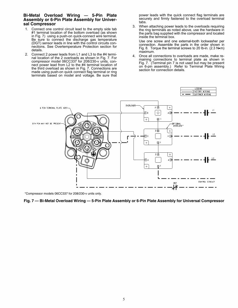
Bi-Metal Overload Wiring — 5-Pin PlateAssembly or 6-Pin Plate Assembly for Univer-sal Compressor1. Connect one control circuit lead to the empty side tab
#1 terminal location of the bottom overload (as shownin Fig. 7) using a push-on quick-connect wire terminal.Be sure to connect the discharge gas temperature(DGT) sensor leads in line with the control circuits con-nections. See Overtemperature Protection section fordetails.
2. Connect 2 power leads from L1 and L3 to the #4 termi-nal location of the 2 overloads as shown in Fig. 7. Forcompressor model 06CC337 for 208/230-v units, con-nect power lead from L2 to the #4 terminal location ofthe third overload as shown in Fig. 7. Connections aremade using push-on quick connect flag terminal or ringterminals based on model and voltage. Be sure that
power leads with the quick connect flag terminals aresecurely and firmly fastened to the overload terminaltabs.
3. When attaching power leads to the overloads requiringthe ring terminals as noted above, use the hardware inthe parts bag supplied with the compressor and locatedinside the terminal box.Use one screw and one external-tooth lockwasher perconnection. Assemble the parts in the order shown inFig. 8. Torque the terminal screws to 20 lb-in. (2.3 Nm)maximum.
4. Once all connections to overloads are made, make re-maining connections to terminal plate as shown inFig. 7. (Terminal pin 7 is not used but may be presenton 6-pin assembly.) Refer to Terminal Plate Wiringsection for connection details.
*Compressor models 06CC337 for 208/230-v units only.
Fig. 7 — Bi-Metal Overload Wiring — 5-Pin Plate Assembly or 6-Pin Plate Assembly for Universal Compressor
*
6
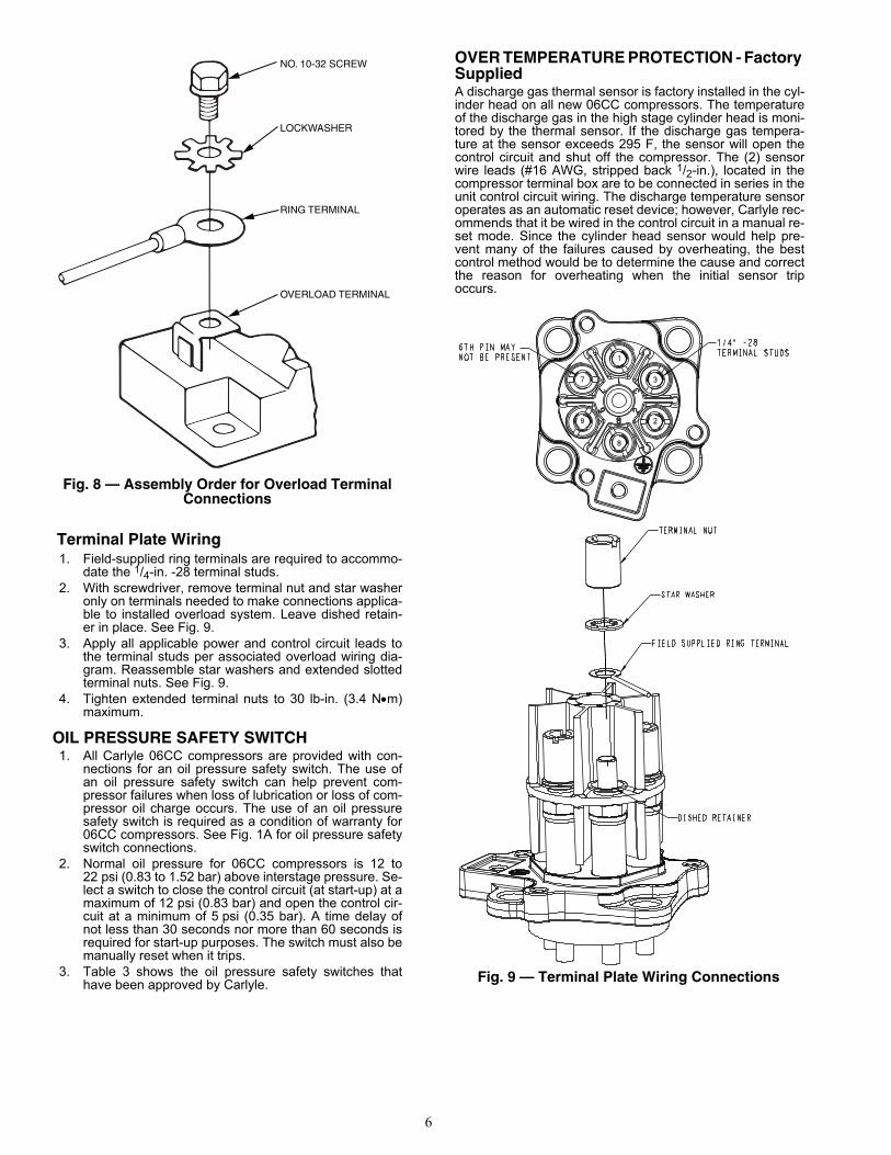
Terminal Plate Wiring1. Field-supplied ring terminals are required to accommo-
date the 1/4-in. -28 terminal studs.2. With screwdriver, remove terminal nut and star washer
only on terminals needed to make connections applica-ble to installed overload system. Leave dished retain-er in place. See Fig. 9.
3. Apply all applicable power and control circuit leads tothe terminal studs per associated overload wiring dia-gram. Reassemble star washers and extended slottedterminal nuts. See Fig. 9.
4. Tighten extended terminal nuts to 30 lb-in. (3.4 Nm)maximum.
OIL PRESSURE SAFETY SWITCH1. All Carlyle 06CC compressors are provided with con-
nections for an oil pressure safety switch. The use ofan oil pressure safety switch can help prevent com-pressor failures when loss of lubrication or loss of com-pressor oil charge occurs. The use of an oil pressuresafety switch is required as a condition of warranty for06CC compressors. See Fig. 1A for oil pressure safetyswitch connections.
2. Normal oil pressure for 06CC compressors is 12 to22 psi (0.83 to 1.52 bar) above interstage pressure. Se-lect a switch to close the control circuit (at start-up) at amaximum of 12 psi (0.83 bar) and open the control cir-cuit at a minimum of 5 psi (0.35 bar). A time delay ofnot less than 30 seconds nor more than 60 seconds isrequired for start-up purposes. The switch must also bemanually reset when it trips.
3. Table 3 shows the oil pressure safety switches thathave been approved by Carlyle.
OVER TEMPERATURE PROTECTION - FactorySuppliedA discharge gas thermal sensor is factory installed in the cyl-inder head on all new 06CC compressors. The temperatureof the discharge gas in the high stage cylinder head is moni-tored by the thermal sensor. If the discharge gas tempera-ture at the sensor exceeds 295 F, the sensor will open thecontrol circuit and shut off the compressor. The (2) sensorwire leads (#16 AWG, stripped back 1/2-in.), located in thecompressor terminal box are to be connected in series in theunit control circuit wiring. The discharge temperature sensoroperates as an automatic reset device; however, Carlyle rec-ommends that it be wired in the control circuit in a manual re-set mode. Since the cylinder head sensor would help pre-vent many of the failures caused by overheating, the bestcontrol method would be to determine the cause and correctthe reason for overheating when the initial sensor tripoccurs.
NO. 10-32 SCREW
LOCKWASHER
RING TERMINAL
OVERLOAD TERMINAL
Fig. 8 — Assembly Order for Overload TerminalConnections
Fig. 9 — Terminal Plate Wiring Connections

7
Table 3 — Oil Pressure Safety SwitchesCARLYLE
ANDCARRIERPART NO.
DANFOSSPART NO. TIME DELAY CONNECTIONS
PRESSURE DIFFERENTIAL —psi (bar) VOLTS
(60 Hz) RESET
REMOTEALARMCIRCUIT
CAPABILITYCut-in Cut-out
634-2008 ORP529-2130 60B2101
45 sec
1/4-in MaleFlares
8-11(0.55-0.76)
4-8(0.28-0.55) 115/230 Manual Yes
634-2050 ORP529-2110 60B2151
36-in Lg. Cap.Tube 1/4-inSAE
Nuts06DA660015Electronic Oil
SwitchN/A 45 sec
Electrical Switchwithout Ext.
Tubing
8-11(0.55-0.76)
4-6(0.28-0.41) 115/230 Manual Yes

CARLYLE COMPRESSOR DIVISION • © CARRIER CORPORATIONP.O. Box 4808 • Syracuse, New York 13221Phone: In U.S. and Puerto Rico: 1-800-GO-CARLYLE
In Canada: 1-800-258-1123In Mexico: 001-800-462-2759www.carlylecompressor.com
Manufacturer reserves the right to discontinue, or changeat any time, specifications or designs without notice andwithout incurring obligations.
Lit. No. 570-849Rev. A 12/15
Replaces: 06CC500011