instabus KNX/EIB System Continuous regulator / Object ... · PDF fileinstabus KNX/EIB System...
82
instabus KNX/EIB System Sensor 07/17 2100-xx/2101 xx Page 1/82 Subject to change without notice Product name: Continuous regulator / Object regulator Design: flush-mounting device (FMD) Article-no.: 2100 xx (Continuous regulator) / 2101 xx (Object regulator) ETS search path: Gira Giersiepen / Input / binary input, 4-fold / continuous-action controller Gira Giersiepen / Input / binary input, 4-fold / object-action controller Gira Giersiepen / ventilation, air conditioning / controller / continuous-action controller Gira Giersiepen / ventilation, air conditioning / controller / object-action controller Functions: Room temperature controller functions: The room temperature controller can be used to control the temperature of individual rooms. Depending on the control option of the current temperature-setpoint and the room temperature, an actuating variable for the heating or cooling control system can be transmitted to the KNX / EIB. The room temperature can optionally be sensed by the internal temperature sensor or by an external temperature sensor connected to the terminal strip of the push-button interface. As a supplement to basic heating or cooling, an additional stage can also be activated. The temperature setpoint difference between the basic and the additional stage can be set in a parameter. For larger deviations between the setpoint and actual temperature value, the room can therefore be heated up or cooled down more quickly by switching on the additional stage. The basic and the additional stage can have different control algorithms assigned to them. The controller can operate in 5 operating modes (comfort, standby, night, frost/ heat protection and controller disable) each having their own temperature setpoints for the heating mode or cooling mode. For the heating and cooling functions continuous-action or switching PI or switching 2-point control characteristics can be selected. Push-button interface functions: The pushbutton interface has four independent channels which – depending on parameterization – can work as inputs or alternatively as outputs (channels 1 or 2 only). Thus, the pushbutton interface can read up to 4 pushbutton/switching states with a common reference potential via its potential-free inputs and transmit the corresponding telegrams to the KNX / EIB. The telegrams can be telegrams for switching or dimming, for blind/shutter control or for value transmitter applications (dimming value transmitter, light-scene extension, temperature or brightness value transmitter). As independent outputs, channels 1 and 2 can alternatively control up to 2 LEDs. To increase the output current capability (cf. technical data), these channels can also be connected in parallel, if they have the same parameterization. The outputs are short-circuit-proof and protected against overload and polarity reversal. Channel 4 can optionally also be used as an external sensor for the room temperature controller or as a temperature limiter when a radiant floor heating system is installed. Connecting 230 V signals or other external voltages to the inputs is not permitted. Illustration: Dimensions: Controls / terminals: A B CD E F G H I J K L Continuous regulator Width: 60 mm Height: 60 mm Depth: 50 mm Overall device dimensions depending on design variant. A: Presence key B: Status LED green, comfort mode C: Status LED green, standby mode D Status LED green, night mode E Status-LED yellow, energy supply F Status LED red, heating G: Status LED blue, cooling H: Status LED red, frost/heat protection I: Status LED red, dew-point J: Control knob for setpoint adjustment K: programming LED under control knob L: programming key, under control knob
Transcript of instabus KNX/EIB System Continuous regulator / Object ... · PDF fileinstabus KNX/EIB System...

instabus KNX/EIB System
Sensor
07/17 2100-xx/2101 xx Page 1/82 Subject to change without notice
Product name: Continuous regulator / Object regulator Design: flush-mounting device (FMD) Article-no.: 2100 xx (Continuous regulator) / 2101 xx (Object regulator) ETS search path: Gira Giersiepen / Input / binary input, 4-fold / continuous-action controller
Gira Giersiepen / Input / binary input, 4-fold / object-action controller Gira Giersiepen / ventilation, air conditioning / controller / continuous-action controller Gira Giersiepen / ventilation, air conditioning / controller / object-action controller
Functions: Room temperature controller functions: The room temperature controller can be used to control the temperature of individual rooms. Depending on the control option of the current temperature-setpoint and the room temperature, an actuating variable for the heating or cooling control system can be transmitted to the KNX / EIB.
The room temperature can optionally be sensed by the internal temperature sensor or by an external temperature sensor connected to the terminal strip of the push-button interface. As a supplement to basic heating or cooling, an additional stage can also be activated. The temperature setpoint difference between the basic and the additional stage can be set in a parameter. For larger deviations between the setpoint and actual temperature value, the room can therefore be heated up or cooled down more quickly by switching on the additional stage. The basic and the additional stage can have different control algorithms assigned to them.
The controller can operate in 5 operating modes (comfort, standby, night, frost/ heat protection and controller disable) each having their own temperature setpoints for the heating mode or cooling mode. For the heating and cooling functions continuous-action or switching PI or switching 2-point control characteristics can be selected. Push-button interface functions: The pushbutton interface has four independent channels which – depending on parameterization – can work as inputs or alternatively as outputs (channels 1 or 2 only). Thus, the pushbutton interface can read up to 4 pushbutton/switching states with a common reference potential via its potential-free inputs and transmit the corresponding telegrams to the KNX / EIB. The telegrams can be telegrams for switching or dimming, for blind/shutter control or for value transmitter applications (dimming value transmitter, light-scene extension, temperature or brightness value transmitter). As independent outputs, channels 1 and 2 can alternatively control up to 2 LEDs. To increase the output current capability (cf. technical data), these channels can also be connected in parallel, if they have the same parameterization. The outputs are short-circuit-proof and protected against overload and polarity reversal.
Channel 4 can optionally also be used as an external sensor for the room temperature controller or as a temperature limiter when a radiant floor heating system is installed.
Connecting 230 V signals or other external voltages to the inputs is not permitted. Illustration: Dimensions: Controls / terminals:
A
B C D
EFGHI J
KL
Continuous regulator
Width: 60 mm Height: 60 mm Depth: 50 mm
Overall device dimensions depending on design variant.
A: Presence key B: Status LED green, comfort mode C: Status LED green, standby mode D Status LED green, night mode E Status-LED yellow, energy supply F Status LED red, heating G: Status LED blue, cooling H: Status LED red, frost/heat protection I: Status LED red, dew-point J: Control knob for setpoint adjustment K: programming LED under control knob L: programming key, under control knob

instabus KNX/EIB System
Sensor
2/82 Page 2100-xx/2101 xx 07/17
Subject to change without notice
Object controller The continuous-action controller is also available without control elements. This variant is called object controller. This means that the object controller has no status LEDs (B - I) no presence key (A) and no control knob (J). The room temperature controller and pushbutton interface functions are however the same as in the continuous-action controller. The room temperature controller function of the object controller is operated exclusively by means of telegrams via the bus. (The object controller has other article nos. and similar ETS search paths.) Illustration: Dimensions: Controls / terminals:
Object controller
Width: 60 mm Height: 60 mm Depth: 50 mm
Overall device dimensions depending on design variant.
–

instabus KNX/EIB System
Sensor
07/17 2100-xx/2101 xx Page 3/82 Subject to change without notice
Technische Daten: Instabus EIB supply
Voltage: 21 – 32 V DC Power consumption: typically 150 mW Connection: bus connecting terminal (KNX type 5.1)
External supply --- room temperature controller (internal temperature sensor):
Measuring range: 0 °C … + 40 °C ±1 % Resolution: 0.1 K Air humidity: 0 % ... 95 % (no condensation)
Response to bus voltage failure Bus voltage only: all object values will be deleted.
room temperature controller: no response, control off pushbutton interface no response (outputs switched off)
Mains voltage only: --- Bus and mains voltage: ---
Response on return of voltage Bus voltage only: room temperature controller: the controller is initialized;
depending on parameterization, different temperature values and the status will be transmitted and the switch-over objects will be updated. pushbutton interface the behaviour of the inputs and outputs can be parameterized.
Mains voltage only: --- Bus and mains voltage: ---
Input: Number: up to 4 (depending on parameterization: channel 1 to 4) Connection screw terminals 0.3 mm² to 1.5 mm² single-wire
max. 1.0 mm² single-wire without ferrule Cable length: binary inputs: max. 5 m
external temperature sensor: 4 m prefabricated, extendible up to 50 m max.
Scanning voltage: continuous signal Loop resistance: 2 kohms max. for safe detection of a "1" signal (rising edge)
Output: Number: up to 2 (depending on parameterization: channel 1 and/or 2) Cable length: max. 5 m Output current: max. 0.8 mA per output channel
(at 1.5 V; typically for red low-current LED) for parallel connection, the maximum total current rises to 1.6 mA For parallel connection it is indispensable that outputs 1 and 2 have exactly the same parameterization (none of the output signal must be a blinking signal!). The outputs are protected against short-circuits, overload and polarity reversal.
Output voltage: typically 1.5 V (e.g. red low-current LED) (5 V output open circuit)
Type of protection: IP 20 Safety class: III Mark of approval: KNX / EIB Ambient temperature: -5 °C ... +45 °C Storage / transport temperature: -25 °C ... +70 °C (storage above +45 °C reduces the lifetime) Mounting position: any Minimum distances: none Type of fastening: The connection insert module with its supporting ring is fastened with
screws in the flush-mounting box. The electronic module is plugged into the insert module.

instabus KNX/EIB System
Sensor
4/82 Page 2100-xx/2101 xx 07/17
Subject to change without notice
Wiring diagram / Terminals: Example 1: implementation of 4 binary inputs recommended cable type:
binary inputs 1 … 4: J-Y(St)Y 2 x 2 x 0.8 mm
1
6
5
4
3
2
Example 2: implementation of 2 binary outputs,. 1 binary input, external temperature sensor recommended cable type:
binary outputs: J-Y(St)Y 2 x 2 x 0.8 mm binary input: J-Y(St)Y 2 x 2 x 0.8 mm temperature sensor: 0.75 mm2 stranded wire without ferrule (prefabricated connecting cable) 1.5 mm2 single-wire (for extension of the prefabricated cable to 50 m max.)
1
6
5
4
3
2
V
Hardware information • With 1.5 mm² cross-section, a deep flush-mounting box is required.
• Connection of sensor wires (terminal 1-5): A suitable cable must be selected if the sensor lines are to be laid under the surface. Recommendation: telephone cable J-Y(St)Y 2 x 2 x 0.8 mm.
• Connection of temperature sensor (terminal 5-6) Use of sensor cable 2 x 0.75 mm² without ferrule. The sensor cable can be extended to 50 m max. by using twisted pair cable, e.g. J-Y(St)Y-2x2x0.8

instabus KNX/EIB System
Sensor
07/17 2100-xx/2101 xx Page 5/82 Subject to change without notice
Software description: ETS search path:
Gira Giersiepen / Input / binary input, 4-fold / continuous-action controller Gira Giersiepen / ventilation, air conditioning / controller / continuous-action controller
Gira Giersiepen / Input / binary input, 4-fold / object-action controller Gira Giersiepen / ventilation, air conditioning / controller / object-action controller
Applications: Short description: Name: Date: Page: Version: Room temperature controller with pushbutton interface
Continuous-action controller with pushbutton interface 4-fold 705C01 (ETS 2)
12.06 6 0.1
Continuous-action controller with pushbutton interface 4-fold 705C10 (ETS 3)

instabus KNX/EIB System
Sensor
6/82 Page 2100-xx/2101 xx 07/17
Subject to change without notice
Application: Continuous-action controller with pushbutton interface, 4-fold 705C Scope of functions
Pushbutton interface functions: General • Switching, dimming, shutter/blind and value transmitter functions freely assignable to the max. 4 inputs • Disable object for disabling of individual inputs (polarity of disable object presettable) • Delay on return of bus voltage and debouncing time centrally adjustable • Response to bus voltage return separately parameterizable for each input • Telegram rate limitation generally parameterizable for all inputs Switching function • Two independent switching objects available for each input (switching commands individually
parameterizable) • Command for rising and falling edge individually adjustable (ON, OFF, TOGGLE, no reaction). • Independent cyclical transmission of switching objects depending on edge or on object value selectable. Dimming function • Single-sided and double-sided actuation • Time between dimming and switching and dimming step width presettable • Telegram repetition and stop telegram transmission possible Shutter/blind function • Command on rising edge adjustable (no function, UP, DOWN, TOGGLE) • Operation concept parameterizable ("step - move – step" resp. "move – step") • Time between short-time and long-time operation presettable (only with "step - move - step") • Slat adjustment time presettable (time during which a "Move" command can be terminated by releasing a
push-button on the input) Dimming value transmitter function • Nature of edge (push-button as make contact, push-button as break contact, switch) and value of edge
parameterizable • Value change in push-button mode possible with long press on the button for value transmitter Light-scene extension function • Nature of edge (push-button as n.o. contact, push-button as n.c. contact, switch) and value of edge
parameterizable • Value adjustment via long key press possible • In light-scene extension with storage function, a light-scene can be stored without preceding recall Temperature and brightness value transmitter • Nature of edge (push-button as n.o. contact, push-button as n.c. contact, switch) and value of edge
parameterizable • Value change in push-button mode possible with long press on the button Temperature sensor function • Channel 4 of the pushbutton interface can be used as external temperature sensor for the room
temperature controller. Outputs: • Independent switching of the maximum of 2 outputs • Optionally output of a 1-bit actuating variable of the room temperature controller or a separate switching
object. • The current switching status of the output can be issued for status indication purposes via a 1-bit object.
instabus KNX/EIB System
Sensor
07/17 2100-xx/2101 xx Page 7/82 Subject to change without notice
Room temperature controller functions: General • 5 operating modes: Comfort, standby, night, frost/heat protection and controller disable • Operating modes switch-over via 1-byte object according to KONNEX or individual 1-bit objects. Heating/cooling system • Control options: heating", "cooling", "heating and cooling" each with or without additional stage. • PI control (continuous or switching PWM) or 2-state control (switching) adjustable as control algorithms. • Continuous (1-byte) or switching (1-bit) actuating variable output. • Control parameter for PI controller (if desired: proportional range, integral-action time) and 2-state
controller (hysteresis) presettable. Setpoint values • Each operating mode can be assigned its own temperature setpoints (for heating and/or cooling). • The setpoints for the additional stage are derived via a parameterizable stage offset from the values of the
basic stage. • Setpoint value shifting by local operation on device or via communication objects. Functions • Automatic or object-oriented switch-over between "heating" and "cooling". • The controller operation can optionally be disabled via an object. • Parameterizable duration of the comfort mode extension. • Complete (1-byte) or partial (1-bit) status information parameterizable and transmissible to the bus via an
object. • Deactivation of the control or of the additional stage via different objects possible. Room temperature measurement • Internal and external room temperature sensor available. • Internal to external determination of measured value with enabled external sensor. • Request interval of external temperature sensor adjustable. • The actual and setpoint temperature can be output to the bus if a parameterizable deviation is detected
(also cyclically). • The room temperature measurement (actual value) can be adjusted separately for the internal and
external sensor via parameter. • Frost/heat protection switch-over depending on window state. • Temperature alarm with upper and lower temperature limit possible. Telegram activation via two separate
objects. Actuating variable output • Separate or combined actuating variable output via one or two objects in "heating and cooling" mode • Normal or inverted actuating variable output parameterizable • Automatic transmission and cycle time for actuating output parameterizable

instabus KNX/EIB System
Sensor
8/82 Page 2100-xx/2101 xx 07/17
Subject to change without notice
Objects for the pushbutton interface: Object Object description
0 – 3 Switching object X.1 1-bit object for transmission of switching telegrams (ON, OFF) (1st switching object)
4 – 7 Switching object X.2 1-bit object for transmission of switching telegrams (ON, OFF) (2nd switching object)
0 – 3 Switching: 1- bit object for transmitting switching telegrams (ON, OFF) for the dimming function
4 – 7 Dimming: 4-bit object for relative brightness variation between 0 and 100 %
0 – 3 Short-time operation 1-bit object for short-time operation of a blind/shutter
4 – 7 Long-time operation 1-bit object for long-time operation of a blind/shutter
0 – 3 Value: 1-byte object for the transmission of value telegrams (0 - 255)
0 – 3 Light-scene extension: 1-byte object for recalling and storing light-scenes (1 - 64)
0 – 3 Temperature value: 2-byte object for adjusting a fixed temperature value (0 - 40 °C)
0 – 3 Brightness value: 2-byte object for adjusting a fixed brightness value between 0 and 1500
8 – 11 Disabling: 1-bit object for disabling individual binary inputs (polarity parameterizable)
8 – 11 Disabling Switching object X.1
1-bit object for disabling individual binary inputs (polarity parameterizable)
12 - 15 Disabling Switching object X.2
1-bit object for disabling individual binary inputs (polarity parameterizable)
3 Floor temperature: 2-byte object for transmitting the current floor temperature when the temperature limiter is operational
4 – 5 External switching object:
1-bit object for control of an (LED) output
0 – 1 Switching: 1-bit object for switching status feedback of an output

instabus KNX/EIB System
Sensor
07/17 2100-xx/2101 xx Page 9/82 Subject to change without notice
Objects for the room temperature controller: Object Object description
23 Actual temperature: 2-byte object for transmission of the actual temperature (room temperature) as measured and varied by a controller or a controller extension. (possible range of values: -99.9 °C ... +99.9 °C / Measuring range of internal temperature sensor: 0 °C ... + 40 °C (1 %)
24 External temperature sensor
2-byte object for connection of an external room temperature sensor or a controller extension (via "actual temperature" object). (possible range of values: -99.9 °C ... +99.9 °C)
26 Basic setpoint: 2-byte object for external preset of basic setpoint. Depending on heating/cooling, the possible range of values is limited by the parameterized frost protection and/or heat protection temperature. The received value is mathematically rounded off to half °C!
28 Operating mode switch-over:
1-byte object for switch-over of the controller’s operating modes acc. to KONNEX.
28 Comfort operation: 1-bit object for switch-over into the "Comfort" operating mode.
29 Standby operation: 1-bit object for switch-over into the "Standby" operating mode.
30 Night-time operation: 1-bit object for switch-over into the "Night" operating mode.
31 Frost/ heat protection: 1-bit object for switch-over into the "Frost/heat protection" operating mode.
32 Forced-control object operating mode:
1-byte object for superordinated forced control of the controller’s operating modes acc. to KONNEX.
33 Presence object: 1-bit object (bi-directional) which transmits the status of the presence key to the bus after pressing or which can be used for connection of a presence detector. (presence detected = "1", presence not detected = "0")
34 Window status: 1-bit object for the connection of window contacts. (window open = "1", window closed = "0")
35 Heating / cooling change-over:
1-bit object for switching over between control options "heating" and "cooling, if not done by the controller automatically (object value 1: heating; object value 0: cooling). In case of automatic switch-over the active control option can be transmitted (parameter-dependent).
36 Controller status: 1-byte object for general status feedback
36 Controller status: 1-bit object for individual status feedback of parameterizable functions of the controller (frost alarm, heating/cooling, comfort mode, night mode, standby mode, controller disabled, controller inactive, frost/heat protection).
instabus KNX/EIB System
Sensor
10/82 Page 2100-xx/2101 xx 07/17
Subject to change without notice
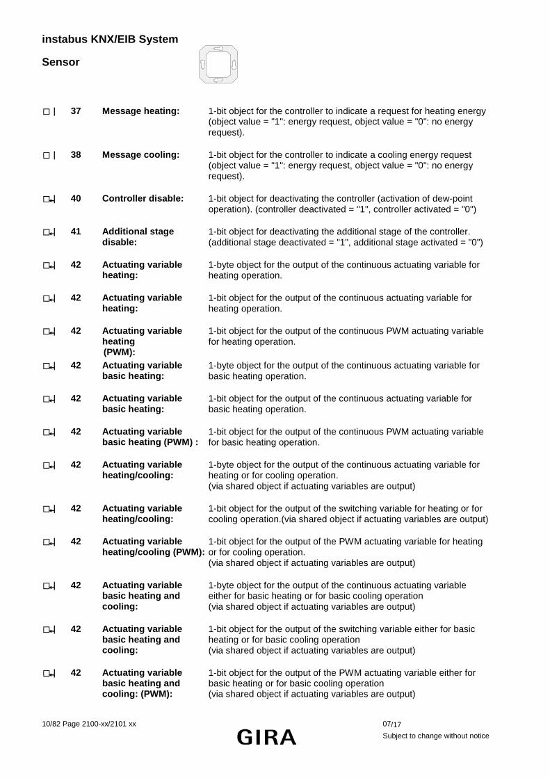
37 Message heating: 1-bit object for the controller to indicate a request for heating energy (object value = "1": energy request, object value = "0": no energy request).
38 Message cooling: 1-bit object for the controller to indicate a cooling energy request (object value = "1": energy request, object value = "0": no energy request).
40 Controller disable: 1-bit object for deactivating the controller (activation of dew-point operation). (controller deactivated = "1", controller activated = "0")
41 Additional stage disable:
1-bit object for deactivating the additional stage of the controller. (additional stage deactivated = "1", additional stage activated = "0")
42 Actuating variable heating:
1-byte object for the output of the continuous actuating variable for heating operation.
42 Actuating variable heating:
1-bit object for the output of the continuous actuating variable for heating operation.
42 Actuating variable heating (PWM):
1-bit object for the output of the continuous PWM actuating variable for heating operation.
42 Actuating variable basic heating:
1-byte object for the output of the continuous actuating variable for basic heating operation.
42 Actuating variable basic heating:
1-bit object for the output of the continuous actuating variable for basic heating operation.
42 Actuating variable basic heating (PWM) :
1-bit object for the output of the continuous PWM actuating variable for basic heating operation.
42 Actuating variable heating/cooling:
1-byte object for the output of the continuous actuating variable for heating or for cooling operation. (via shared object if actuating variables are output)
42 Actuating variable heating/cooling:
1-bit object for the output of the switching variable for heating or for cooling operation.(via shared object if actuating variables are output)
42 Actuating variable heating/cooling (PWM):
1-bit object for the output of the PWM actuating variable for heating or for cooling operation. (via shared object if actuating variables are output)
42 Actuating variable basic heating and cooling:
1-byte object for the output of the continuous actuating variable either for basic heating or for basic cooling operation (via shared object if actuating variables are output)
42 Actuating variable basic heating and cooling:
1-bit object for the output of the switching variable either for basic heating or for basic cooling operation (via shared object if actuating variables are output)
42 Actuating variable basic heating and cooling: (PWM):
1-bit object for the output of the PWM actuating variable either for basic heating or for basic cooling operation (via shared object if actuating variables are output)

instabus KNX/EIB System
Sensor
07/17 2100-xx/2101 xx Page 11/82 Subject to change without notice
43 Actuating variable additional heating:
1-byte object for the output of the continuous actuating variable for additional heating operation.
43 Actuating variable additional heating:
1-bit object for the output of the switching variable for heating operation.
43 Actuating variable additional heating (PWM):
1-bit object for the output of the PWM actuating variable for additional heating operation
43 Actuating variable additional heating and cooling:
1-byte object for the output of the continuous actuating variable either for additional heating or cooling operation (via shared object if actuating variables are output)
43 Actuating variable additional heating and cooling:
1-bit object for the output of the switching variable either for additional heating or cooling operation (via shared object if actuating variables are output)
43 Actuating variable additional heating and cooling: (PWM):
1-bit object for the output of the PWM actuating variable either for additional heating or cooling operation (via shared object if actuating variables are output)
44 Actuating variable cooling:
1-byte object for the output of the continuous actuating variable for cooling operation.
44 Actuating variable cooling:
1-bit object for the output of the switching variable for heating operation.
44 Actuating variable cooling (PWM):
1-bit object for the output of the PWM actuating variable for cooling operation
44 Actuating variable basic cooling:
1-byte object for the output of the continuous actuating variable for basic cooling operation
44 Actuating variable basic cooling:
1-bit object for the output of the switching variable for basic cooling operation
44 Actuating variable basic cooling (PWM):
1-bit object for the output of the PWM actuating variable for basic cooling operation
45 Actuating variable additional cooling:
1-byte object for the output of the continuous actuating variable for additional cooling operation
45 Actuating variable additional cooling:
1-bit object for the output of the switching variable for additional heating operation.
45 Actuating variable additional cooling (PWM):
1-bit object for the output of the PWM actuating variable for additional cooling operation.
46 PWM actuating variable Heating:
1-byte object with PWM actuating variable for status feedback of the actuating variable value for heating operation
46 PWM actuating variable Basic heating:
1-byte object with PWM actuating variable for status feedback of the continuous actuating variable value for basic heating operation

instabus KNX/EIB System
Sensor
12/82 Page 2100-xx/2101 xx 07/17
Subject to change without notice
47 PWM actuating variable Additional heating:
1-byte object with PWM actuating variable for status feedback of the continuous actuating variable value for additional heating..
48 PWM actuating variable Cooling:
1-byte object with PWM actuating variable for status feedback of the continuous actuating variable value for cooling operation
48 PWM actuating variable Basic cooling:
1-byte object with PWM actuating variable for status feedback of the continuous actuating variable value for basic cooling operation
49 PWM actuating variable Additional cooling:
1-byte object with PWM actuating variable for status feedback of the continuous actuating variable value for additional cooling operation
50 Setpoint temperature: 2-byte object for the output of the current temperature. Depending on the control option, the possible range of values is limited by the parameterized frost protection and/or heat protection temperature.
50 Setpoint temperature: 2-byte object for receiving the current temperature setpoint of a controller.
52 Feedback setpoint shift:
1-byte object for current setpoint shift feedback x ≤ 0 ≤ y (0 = no active shifting); integers The possible range of values (x to y) is fixed by the setting of the upper and lower limits for the setpoint (parameterizable) in combination with the step value (0.5 °C).
53 Preset setpoint shift 1-byte object for presetting a basic setpoint shift, e.g. via a controller extension. x ≤ 0 ≤ y (0 = no active shifting); integers The possible range of values (x to y) is fixed by the setting of the upper and lower limits for the setpoint (parameterizable) in combination with the step value (0.5 °C). In case the limits of the value range are exceeded by the preset external value, the controller will automatically reset the received value to the minimum and maximum limits.
57 Additional status feedback
1-byte object for general additional status feedback
58 Actual temperature not adjusted
2-byte object for the output of the actual temperature (room temperature) as measured and not adjusted by the controller. (possible range of values: -99.9 °C ... +99.9 °C / Measuring range of internal temperature sensor: 0 °C to + 40 °C ±1 %)

instabus KNX/EIB System
Sensor
07/17 2100-xx/2101 xx Page 13/82 Subject to change without notice
Number of addresses (max): 120 dynamic table handling Yes No Number of assignments (max): 120 maximum length of table 120 Communication objects:
59
Pushbutton interface functions:
Function: Binary input / switching (for all 4 binary inputs (X = 1 to 4)) disabling function enabled
Object-Nr. Function Name DPT–ID Type Flag
0-3 Switching object X.1 PBI input X 1.001 1 bit C, T
4-7 Switching object X.2 PBI input X 1.001 1 bit C, T
8-11 Disable switching object X.1 PBI input X 1.001 1 bit C, W
12-15 Disable switching object X.2 PBI input X 1.001 1 bit C, W
Function: Binary input / dimming (for all 4 binary inputs (X = 1 to 4)) disabling function enabled
Object-Nr. Function Name DPT–ID Type Flag
0-3 Switching PBI input X 1.001 1 bit C, T
4-7 dimming PBI input X 3.007 4 bit C, T
8-11 Disabling PBI input X 1.001 1 bit C, W
Function: Binary input / blind/shutter (for all 4 binary inputs (X = 1 to 4)) disabling function enabled
Object-Nr. Function Name DPT–ID Type Flag
0-3 Short-time operation PBI input X 1.007 1 bit C, T
4-7 Long-time operation PBI input X 1.008 1 bit C, T
8-11 Disabling PBI input X 1.001 1 bit C, W
Function: Binary input / dimming value transmitter (for all 4 binary inputs (X = 1 to 4)) disabling function enabled
Object-Nr. Function Name DPT–ID Type Flag
0-3 Value PBI input X 5.001 1 byte C, T
8-11 Disabling PBI input X 1.001 1 bit C, W
Function: Binary input / light-scene extension (for all 4 binary inputs (X = 1 to 4)) disabling function enabled
Object-Nr. Function Name DPT–ID Type Flag
0-3 Light-scene extension PBI input X 18.001 1 byte C, T
8-11 Disabling PBI input X 1.001 1 bit C, W
Function: Binary input / brightness value transmitter (for all 4 binary inputs (X = 1 to 4)) disabling function enabled
Object-Nr. Function Name DPT–ID Type Flag
0-3 Brightness value PBI input X 9.004 2 bytes C, T
8-11 Disabling PBI input X 1.001 1 bit C, W

instabus KNX/EIB System
Sensor
14/82 Page 2100-xx/2101 xx 07/17
Subject to change without notice
Function: Binary input / temperature value transmitter (for all 4 binary inputs (X = 1 to 4)) disabling function enabled
Object-Nr. Function Name DPT–ID Type Flag
0-3 Temperature value PBI input X 9.001 2 bytes C, T
8-11 Disabling PBI input X 1.001 1 bit C, W
Function: output / basic stage ... or additional stage ... (for channels 1 and 2 (Y = 1 to 2))
Object-Nr. Function Name DPT–ID Type Flag
0-1 Switching PBI output Y 1.001 1 bit C, T
Function: output / output external switching object ... (for channels 1 and 2 (Y = 1 to 2))
Object-Nr. Function Name DPT–ID Type Flag
0-1 Switching PBI output Y 1.001 1 bit C, T
4-5 external switching object PBI output Y 1.001 1 bit C, W
Function: external temperature sensor (for channel 4)
Object-Nr. Function Name DPT–ID Type Flag If channel 4 is used as an external temperature sensor for the room temperature controller, its measuring value is internally written into communication object 24 "External temperature sensor" of the controller. To avoid malfunctions, it is not permitted to write other values from outside into this object.
Function: temperature limiter (for channel 4)
Object-Nr. Function Name DPT–ID Type Flag
3 floor temperature PBI input 4 9.001 2 bytes C, T

instabus KNX/EIB System
Sensor
07/17 2100-xx/2101 xx Page 15/82 Subject to change without notice
Room temperature controller functions:
Function: Actual temperature
Object-Nr. Function Name DPT–ID Type Flag 23 Actual temperature RTC output 9.001 2 bytes C, R, T
Function: additional temperature sensor
Object-Nr. Function Name DPT–ID Type Flag
24 External temperature sensor RTC input 9.001 2 bytes C, W, T
Function: basic setpoint preset
Object-Nr. Function Name DPT–ID Type Flag
26 Basic setpoint RTC input 9.001 2 bytes C, W
Function: Operating mode switch-over With operating mode switch-over "via value (1 byte)": Object-Nr. Function Name DPT–ID Type Flag
28 Operating mode switch-over RTC input 20.102 1 byte C, W(, T)1
32 Operating mode forcing object RTC input 20.102 1 byte C, W With operating mode switch-over "via switching (4 x 1 bit)": Object-Nr. Function Name DPT–ID Type Flag
28 Comfort mode RTC input 1.001 1 bit C, W(, T)1
29 Standby mode RTC input 1.001 1 bit C, W(, T)1
30 Night mode RTC input 1.001 1 bit C, W(, T)1
31 Frost/ heat protection RTC input 1.001 1 bit C, W(, T)1 Presence object and window status: Object-Nr. Function Name DPT–ID Type Flag
33 Presence object RTC input / output 1.001 1 bit C, W, T
34 Window status RTC input 1.019 1 bit C, W
Function: Control option switch-over
Object-Nr. Function Name DPT–ID Type Flag
35 Heating / cooling switch-over 2 RTC input 1.001 1 bit C, W, (T)

instabus KNX/EIB System
Sensor
16/82 Page 2100-xx/2101 xx 07/17
Subject to change without notice
Function: Status indication
Object-Nr. Function Name DPT–ID Type Flag
36 Controller status RTC output --- 1 byte C, T
36 Controller status, frost alarm RTC output 1.001 1 bit C, T
36 Controller status, heating / cooling
RTC output 1.001 1 bit C, T
36 Controller status, comfort mode
RTC output 1.001 1 bit C, T
36 Controller status, night mode RTC output 1.001 1 bit C, T
36 Controller status, controller disabled
RTC output 1.001 1 bit C, T
36 Controller status, controller inactive
RTC output 1.001 1 bit C, T
36 Controller status, frost / heat protection
RTC output 1.001 1 bit C, T
36 Controller status, standby mode
RTC output 1.001 1 bit C, T
37 Heating message RTC output 1.001 1 bit C, T
38 Cooling message RTC output 1.001 1 bit C, T
Function: Disabling function (room temperature controller)
Object-Nr. Function Name DPT–ID Type Flag
40 Disable controller RTC input 1.001 1 bit C, W
41 Disable additional stage 3 RTC input 1.001 1 bit C, W
Function: Actuating variable heating
no additional stage activated / For mixed operation: Actuating variable output "heating" and "cooling" via separate objects: Object-Nr. Function Name DPT–ID Type Flag
42 Actuating variable heating RTC output 5.001 1 byte C, W, T
42 Actuating variable heating (PWM)
RTC output 1.001 1 bit C, W, T
42 Actuating variable heating RTC output 1.001 1 bit C, W, T no additional stage activated / For mixed operation: Actuating variable output "heating" and "cooling" via shared object: Object-Nr. Function Name DPT–ID Type Flag
42 Actuating variable heating/cooling
RTC output 5.001 1 byte C, W, T
42 Actuating variable heating/cooling (PWM)
RTC output 1.001 1 bit C, W, T
42 Actuating variable heating/cooling
RTC output 1.001 1 bit C, W, T

instabus KNX/EIB System
Sensor
07/17 2100-xx/2101 xx Page 17/82 Subject to change without notice
additional stage activated / For mixed operation: Actuating variable output "heating" and "cooling" via separate objects: Object-Nr. Function Name DPT–ID Type Flag
42 Actuating variable RTC output 5.001 1 byte C, W, T
42 Actuating variable basic heating (PWM)
RTC output 1.001 1 bit C, W, T
42 Actuating variable basic heating
RTC output 1.001 1 bit C, W, T
43 Actuating variable additional heating
RTC output 5.001 1 byte C, W, T
43 Actuating variable additional heating (PWM)
RTC output 1.001 1 bit C, W, T
43 Actuating variable additional heating
RTC output 1.001 1 bit C, W, T
Additional stage activated / For mixed operation: Actuating variable output "heating" and "cooling" via shared object: Object-Nr. Function Name DPT–ID Type Flag
42 Actuating variable basic stage RTC output 5.001 1 byte C, W, T
42 Actuating variable basic stage (PWM)
RTC output 1.001 1 bit C, W, T
42 Actuating variable basic stage RTC output 1.001 1 bit C, W, T
43 Actuating variable additional stage
RTC output 5.001 1 byte C, W, T
43 Actuating variable additional stage (PWM)
RTC output 1.001 1 bit C, W, T
43 Actuating variable additional stage
RTC output 1.001 1 bit C, W, T
Funcion: Actuating variable cooling
no additional stage activated / For mixed-mode: Actuating variable output "heating" and "cooling" via separate objects: Object-Nr. Function Name DPT–ID Type Flag
44 Actuating variable cooling RTC output 5.001 1 byte C, W, T
44 Actuating variable cooling (PWM)
RTC output 1.001 1 bit C, W, T
44 Actuating variable cooling RTC output 1.001 1 bit C, W, T

instabus KNX/EIB System
Sensor
18/82 Page 2100-xx/2101 xx 07/17
Subject to change without notice
additional stage activated / For mixed-mode: Actuating variable output "heating" and "cooling" via separate objects: Object-Nr. Function Name DPT–ID Type Flag
44 Actuating variable basic cooling
RTC output 5.001 1 byte C, W, T
44 Actuating variable basic cooling (PWM)
RTC output 1.001 1 bit C, W, T
44 Actuating variable basic cooling
RTC output 1.001 1 bit C, W, T
45 Actuating variable additional cooling
RTC output 5.001 1 byte C, W, T
45 Actuating variable additional cooling (PWM)
RTC output 1.001 1 bit C, W, T
45 Actuating variable additional cooling
RTC output 1.001 1 bit C, W, T
Function: Actuating variable status indication heating
Object-Nr. Function Name DPT–ID Type Flag
46 PWM actuating variable heating
RTC output 5.001 1 byte C, W, T
46 PWM actuating variable basic heating
RTC output 5.001 1 byte C, W, T
47 PWM actuating variable additional heating
RTC output 5.001 1 byte C, W, T
Function: Actuating variable status information cooling
Object-Nr. Function Name DPT–ID Type Flag
48 PWM actuating variable cooling
RTC output 5.001 1 byte C, W, T
48 PWM actuating variable basic cooling
RTC output 5.001 1 byte C, W, T
49 PWM actuating variable additional cooling
RTC output 5.001 1 byte C, W, T
Function: Setpoint temperature
Object-Nr. Function Name DPT–ID Type Flag 50 Setpoint temperature RTC output 9.001 2 byte C, T, R

instabus KNX/EIB System
Sensor
07/17 2100-xx/2101 xx Page 19/82 Subject to change without notice
Function: Controller extension:
Object-Nr. Function Name DPT–ID Type Flag 52 Setpoint shift feedback RTC output 6.010 1 byte C, T, R
53 Setpoint shift preset RTC input 6.010 1 byte C, W
Function: Controller status indication additional stage
Object-Nr. Function Name DPT–ID Type Flag 57 Status report additional stage RTC output --- 1 byte C, T
Function: Actual temperature not adjusted
Object-Nr. Function Name DPT–ID Type Flag 58 Actual temperature not
adjusted RTC output 9.001 2 byte C, T
Independent of the setting of the parameter "Temperature sensing" (internal sensor, external sensor or internal and external sensor), the function shows the non-adjusted (and non-weighted) actual value of the internal temperature sensor. 1: Optionally, the "T" flags can be set for the operating mode switch-over. Once the flags are set, the object
values which have changed according to the newly set operating mode will be actively transmitted to the bus.
2: This object is only visible in mixed operation "heating and cooling" or "basic / additional heating / cooling". The "T" flag is set for automatic heating / cooling switch-over.
3: This object is only visible when additional stage is activated.

instabus KNX/EIB System
Sensor
20/82 Page 2100-xx/2101 xx 07/17
Subject to change without notice
Table of contenta 1 General room temperature controller functions .................................................... 21 2 Room temperature controller functions ................................................................. 24
2.1 Operating modes ............................................................................................................................ 24 2.1.1 Operating mode switch-over ........................................................................................................ 25 2.1.2 Notes on the operating modes ..................................................................................................... 30 2.1.3 Controller status ........................................................................................................................... 32 2.1.4 Additional controller status ........................................................................................................... 33
2.2 Control options and control option switch-over .............................................................................. 34 2.3 Room temperature control and actuating variables ....................................................................... 36
2.3.1 Control algorithms, control circuits and calculation of actuating variable .................................... 36 2.3.2 Adapting the control algorithms ................................................................................................... 41
2.3.2.1 Adapting the PI control ......................................................................................................... 41 2.3.2.2 Adapting the 2-state control .................................................................................................. 43
2.3.3 Actuating variable output ............................................................................................................. 44 2.3.3.1 Actuating variable objects ..................................................................................................... 44 2.3.3.1 Automatic transmission ......................................................................................................... 45
2.4 Temperature setpoints ................................................................................................................... 46 2.4.1 Setpoint presettings in the ETS ................................................................................................... 46
2.4.1.1 Setpoints for the "heating" control option ............................................................................. 47 2.4.1.2 Setpoints for the "cooling" control option .............................................................................. 48 2.4.1.3 Setpoint for the "heating and cooling" control option: ........................................................... 49
2.4.2 Adjusting the setpoints ................................................................................................................. 51 2.4.2.1 Adjusting basic temperature and setpoint temperatures for comfort, standby and night mode 51 2.4.2.2 Basic setpoint shifting ........................................................................................................... 52
2.4.3 Transmitting the setpoint temperature ......................................................................................... 54 2.5 Room temperature measurement .................................................................................................. 54
2.5.1 Temperature detection and determination of measured value .................................................... 55 2.5.2 Calibrating the measured values ................................................................................................. 56 2.5.3 Transmitting the actual temperature ............................................................................................ 56
2.6 Disable functions of the room temperature controller .................................................................... 57 2.6.1 Disabling the control function ....................................................................................................... 57
2.7 Valve protection ............................................................................................................................. 57 3 Pushbutton interface functions .............................................................................. 58
3.1 Binary input functions ..................................................................................................................... 58 3.1.1 "No function" ................................................................................................................................ 58 3.1.2 "Switching" function ...................................................................................................................... 58 3.1.3 "Dimming" function ....................................................................................................................... 58 3.1.4 "Blind/shutter" function ................................................................................................................. 59 3.1.5 "1-byte value transmitter" and 2-byte value transmitter" function ................................................ 60 3.1.6 "Light-scene extension with / without storage" function ............................................................... 61 3.1.7 External temperature sensor ........................................................................................................ 62 3.1.8 Temperature limiter ...................................................................................................................... 62 3.1.9 Behaviour of the inputs on return of bus voltage ......................................................................... 63 3.1.10 Input disable function ................................................................................................................... 63 3.1.11 Cyclical transmission.................................................................................................................... 63
3.2 Description of output functions ....................................................................................................... 64 Parameters ......................................................................................................................... 65

instabus KNX/EIB System
Sensor
07/17 2100-xx/2101 xx Page 21/82 Subject to change without notice
Functional description 1 General room temperature controller functions The room temperature controller supports the three control options "heating", "cooling" and "heating and cooling". In all three control options, the controller can work in different operating modes to which different setpoint temperatures are assigned. The following diagrams show these setpoint temperatures and their graduations.
"Heating"
Comfortmode
Standbymode
Nightmode
Frost/heat prot.mode
Standbyheating
temp. decrease Nightheating
temp. decrease
Frost protectionsetpoint
Temperature
Comfort temp. = basic setpoint
Standby temperature
Night temp.
"Cooling"
Standbycooling
temp. increase
Night cooling
temp. increase
Heat protectionsetpoint
Comfortmode
Standbymode
Nightmode
Frost/heat prot.mode
Temperature
Comfort temp.
Standby temp.
Night temp.
"Heating and cooling"
Standbycooling
temp. increase
Night cooling
temp. increase
Heat protectionsetpoint
Comfortmode
Standbymode
Nightmode
Frost/heat prot.mode
Standbyheating
temp. decrease Nightheating
temp. decrease
Frost protectionsetpoint
Dead band betweenheating and cooling /
symmetrical dead band
Temperature
Basic setpoint
Comfort temp.
Standby temperature
Night temp.
Comfort temp.
Standby temperature
Night temp.
Standbycooling
temp. increase
Nightcooling
temp. increase
Heat protectionsetpoint
Comfortmode
Standbymode
Nightmode
Frost/heat prot. mode
Standbyheating
temp. decrease Nightheating
temp. decrease
Frost protectionsetpoint
Dead band betweenheating and cooling /
asymmetrical dead band
Temperature
Comfort temp. = basic setpoint
Standby temperature
Night temp.
Comfort temp.
Standby temp.
Night temp.

instabus KNX/EIB System
Sensor
22/82 Page 2100-xx/2101 xx 07/17
Subject to change without notice
Temperature control with additional stage considering as an example "heating and cooling" with symmetrical dead zone…
Standbycooling
temp. increase
Nightcooling
temp. increase
Heat protectionsetpoint
Comfortmode
Standbymode
Nightmode
Frost/heat prot.mode
Standby heating
temp. decr. Nightheating
temp. decrease
Frost protectionsetpoint
Dead band betweenheating and cooling /
symmetrical dead band
Temperature
Basic setpoint
Basic stage comfort temp.
Basic stage standby temp.
Basic stage night temp.
Basic stage comfort temp.
Basic stage standby temp.
Additional stage night temp.
SW
SW
SW
SW
SW
SW
Additional stage comf. temp.
Additional stage standby temp.
Additional stage night temp.
Additional stage comf. temp.
Additional stage standby temp.
Additional stage night temp.
SW : Step width parameterized in the ETS plug-in
If enabled in the ETS, 6 temperature setpoints can be varied in "heating and cooling" control option. Depending on the temperature decrease, increase or dead zone parameterized in the ETS, all temperature setpoints are derived from the basic setpoint temperature. It must be pointed out that changing the setpoint temperature for heating in the comfort mode will also change all other setpoint temperature values!
The dead zone (temperature zone for which there is neither heating nor cooling) is the difference between the setpoint temperatures for "heating" and "cooling" in the comfort mode. The following applies:
Tcomfort setpoint cooling – Tcomfort setpoint heating = Tdead zone; Tcomfort setpoint cooling ≥ Tcomfort setpoint heating Important notes:
- If the dead zone is symmetrical, the basic setpoint is indirectly set via the comfort temperature for heating.
- Changing the comfort setpoint temperature for cooling allows the adjustment of the dead zone. An adjustment of the dead zone with a symmetrical dead zone position will result in a shift of the comfort setpoint temperature for heating and thus of all other temperature setpoints. With an asymmetrical dead zone position, an adjustment of the comfort setpoint temperature for cooling will only shift the temperature setpoints for cooling. It is possible to shift the dead zone to 0 °C via local control (Tcomfort setpoint cooling = Tcomfort
setpoint heating). In this case there is neither heating nor cooling, if the determined room temperature equals the comfort setpoint temperatures.
The setpoint temperatures for "Standby" and "Night" are derived from the comfort setpoint temperatures for heating or cooling. The temperature increase (for cooling) and the temperature decrease (for heating) of both operating modes can be preset in the ETS.
instabus KNX/EIB System
Sensor
07/17 2100-xx/2101 xx Page 23/82 Subject to change without notice
In this case, the standby or night setpoint temperatures will always shift together with the temperature increase/decrease resulting from the local control during the adjustment of the basic setpoint temperature or the dead zone. After the reprogramming with the ETS, the originally parameterized values can be accepted again.
The following applies:
Tstandby setpoint heating ≤ Tcomfort setpoint heating ≤ Tcomfort setpoint cooling ≤ Tstandby setpoint cooling
or
Tnight setpoint heating ≤ Tcomfort setpoint heating ≤ Tcomfort setpoint cooling ≤ Tnight setpoint cooling In case of a two-stage control the setpoints of the additional stage are always derived dynamically from the setpoints of the basic stage. The temperature setpoints of the additional stage are predefined by the stage offset which is parameterized in the ETS. The stage offset cannot be adjusted in the local control mode. As far as a change of the basic setpoint temperature is concerned (when a new comfort setpoint temperature value for heating is being received by communication object no. 26), there basically two cases to be distinguished:
- Case 1: The basic setpoint adjustment is permanently adopted, - Case 2: The basic setpoint adjustment is only temporarily adopted (default). Via the "Adopt basic temperature setpoint permanently" parameter on the "Room temperature controller function /setpoints" parameter page, it is possible to determine whether the changed basic temperature value shall be stored in memory permanently ("Yes") or only temporarily ("No"). Case 1:
If the basic temperature setpoint is changed, it will be permanently stored in the room temperature controller's EEPROM. The newly adjusted value will overwrite the basic temperature originally parameterized with the ETS!
It should be noted, however, that frequent adjustments of the basic temperature (e.g. several times a day) can affect the product life of the device as the non-volatile memory is designed only for less frequent write access.
Thus the basic setpoint received by the object remains in memory even after a bus voltage failure.
Case 2:
The basic setpoint received via the object stays only temporarily active in the current operating mode. In case of a bus voltage failure or following a switch-over into another operating mode (e.g. comfort followed by standby), the basic setpoint set via local control or received via the object will be discarded and replaced by the value which was originally parameterized in the ETS.
Notes:
- Since the setpoint temperatures for the "standby" and "night" operating modes or the setpoints for the "cooling" control option are derived - in consideration of the increase, decrease or dead zone values that are parameterized in the ETS - from the basic setpoint temperature for "heating", these setpoint temperatures will shift linearly by the change of the basic setpoint value. The temperature setpoints for the standby or night mode or "cooling" comfort mode (dead zone) will always be stored in the non-volatile EEPROM.
- It has to be pointed out that temperature setpoints can only be changed or stored via the "Basic setpoint" object, if it was enabled in the ETS.

instabus KNX/EIB System
Sensor
24/82 Page 2100-xx/2101 xx 07/17
Subject to change without notice
2 Room temperature controller functions 2.1 Operating modes The room temperature controller features several operating modes. By selecting theses modes it is possible to activate different temperature setpoints that, for example, depend on the presence of a person, the status of the heating or cooling system, the time of day or day of week.
• Comfort mode:
The comfort mode should be activated if people are present in the room that requires the room temperature to be adjusted to a comfortable and appropriate value. The switch-over into this operating mode can also take place via presence control. The comfort mode when activated is signalled by LED B ( ). • Standby mode
If a room is not in use during the day as people are absent, the standby mode may be activated. This will set the room temperature to a standby value thus saving heating or cooling energy in the process. The standby mode when activated is signalled by LED C ( ). • Night mode
During the night hours or during a longer absence it is often best to adjust the room temperature to cooler temperatures for heating systems (e.g. in bedrooms). In this case cooling systems can be adjusted to higher temperature values, if climate control is not required (e.g. in offices). For this purpose the night mode can be activated. The night mode when activated is signalled by LED D ( ). • Frost / heat protection mode
Frost protection is necessary, if, for example, the room temperature must not fall below critical values when the window is open. Heat protection might be necessary, if the temperature in a mostly warm environment becomes too high due to external influences. In these cases a freezing or overheating of the room can be prevented by activating the frost/heat protection depending on the adjusted "heating" or "cooling" control option by specifying an individual temperature setpoint. A frost/heat protection when activated is signalled by LED H ( ). • Comfort mode extension (temporary comfort mode)
The comfort mode extension is to be activated from the night mode or the frost/heat protection (not triggered by the "window state" object) and can be used to adjust the room temperature to the comfort temperature for a certain amount of time, if, for example the room 'is used' during the night as well. The extension is activated exclusively by a parameterized presence key. The comfort mode extension is automatically deactivated after a settable time has elapsed or by pressing the presence key again or via receiving a presence object value = "0". The extension cannot be retriggered.
An individual temperature setpoint can be preset for each "heating" or "cooling" control option.

instabus KNX/EIB System
Sensor
07/17 2100-xx/2101 xx Page 25/82 Subject to change without notice
2.1.1 Operating mode switch-over
There are several ways to activate or switch-over the operating modes. Activating or switching-over – interdependent in terms of priority – are possible via…
a) local operation of the presence key, if enabled,
c) the 1-bit objects that are available separately for each operating mode or alternatively via the KONNEX objects (1 byte).
Ad a): If the presence key has been selected for presence detection on parameter page "Controller functions", the presence key can be used to switch from the night mode or from the frost/heat protection mode over to the comfort mode for the preset comfort extension time on provision that the above modes have not been activated by the "Window state" object. The comfort mode extension is deactivated after this time has elapsed, after a new press on the presence key or after receiving a presence object value = "0". If the duration of the comfort extension is set to "0", the presence function can be activated, but the operating mode is not changed. During the comfort extension period, the comfort LED is lit up together with the "night mode" or the "frost/heat protection" LED. If the standby mode is active, it is possible to switch into the comfort mode by actuating the presence key or via a presence object value = "1".
Ad b): One distinguishes whether the operating mode is to be switched-over via separate 1-bit objects or, alternatively, via the 1-byte KONNEX objects. The "Operating mode switch-over" parameter on the "Controller General" parameter page predefines how the switch-over will take place. • Operating mode switch-over via "switching (4 x 1 bit):
There is a separate 1-bit switch-over object for each operating mode. Each one of these objects allows to switch-over or to preset the current operating mode by priority.
Taking into consideration the priority, the following switch-over hierarchy results from an operating mode switch-over via the objects. One distinguishes between presence detection by presence key (table 1 / figure 1) and by presence detector (table 2 / figure 2 on next page):
Table 1 "Operating mode switch-over" objects: Window
status Obj.-No. 34
Presence key object
Obj.-No. 33
activated operating mode
Obj.-No. 31
Obj.-No. 28
Obj.-No. 29
Obj.-No. 30
X X X X 1 X Frost /heat protection 1 X X X 0 0 Frost /heat protection 0 1 X X 0 0 Comfort 0 0 1 X 0 0 Standby 0 0 0 1 0 0 Night 1 X X X 0 1 Comfort extension 0 1 X X 0 1 Comfort 0 0 1 X 0 1 Comfort 0 0 0 1 0 1 Comfort extension
0 0 0 0 0 0 last available mode 0 0 0 0 0 1 Comfort / comfort mode
extension *
X = irrelevant *: depends on the last available operating mode.

instabus KNX/EIB System
Sensor
26/82 Page 2100-xx/2101 xx 07/17
Subject to change without notice
Fig 1:
1
0Window status object 34
Comfort
1
0
1
0
1
0
Local presence key/precence object
Comfort prolongation
Night
Comfort prologation
Frost/heat prot.
Comfort
Standby
Switch-over objects/ local operation/operating mode after reset
Frost/heat prot.
Operating mode
(possibly delayed)
Table 2 "Operating mode switch-over" objects: Window
status Obj.-No. 34
Presence detector object
Obj.-No. 33
activated operating mode
Obj.-No. 31
Obj.-No. 28
Obj.-No. 29
Obj.-No. 30
X X X X 1 X Frost /heat protection X X X X 0 1 Comfort 1 X X X 0 0 Frost /heat protection 0 1 X X 0 0 Comfort 0 0 1 X 0 0 Standby
0 0 0 1 0 0 Night 0 0 0 0 0 0 last available mode
X = irrelevant
Fig 2:
1
0Window status object 34
Comfort
Night
Frost/heat prot.
Comfort
Standby
Switch-over objects/ local operation/operating mode after reset
Frost/heat protection
Operating mode1
0Presence detector object object 33 (possibly delayed)
instabus KNX/EIB System
Sensor
07/17 2100-xx/2101 xx Page 27/82 Subject to change without notice
Notes on operating mode switch-over via "Switching" (4 x 1-bit):
• When the operating modes are switched-over, the objects, too, (comfort mode / standby mode / night mode / frost/heat protection) will always be updated and can, if applicable, be read out (set "read" flag!). Once the "transmission" flag is set for these objects, changed values will also be actively transmitted to the bus. Following a return of bus voltage or an initialization, the object corresponding to the set operating mode will be updated and its value actively transmitted to the bus when the "transmission" flag is set.
• When parameterizing a presence key: The presence object is active "1") for the duration of an activated comfort mode extension. The presence object will be automatically deleted ("0"), if the comfort mode extension is terminated after the extension time has elapsed or if the operating mode has been switched by a higher-priority control via the switch-over objects or via local operation.
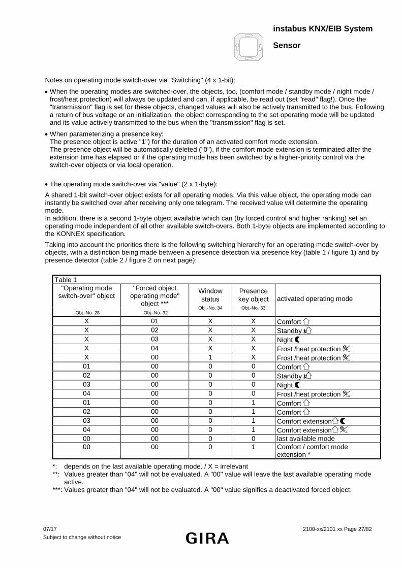
• The operating mode switch-over via "value" (2 x 1-byte):
A shared 1-bit switch-over object exists for all operating modes. Via this value object, the operating mode can instantly be switched over after receiving only one telegram. The received value will determine the operating mode. In addition, there is a second 1-byte object available which can (by forced control and higher ranking) set an operating mode independent of all other available switch-overs. Both 1-byte objects are implemented according to the KONNEX specification.
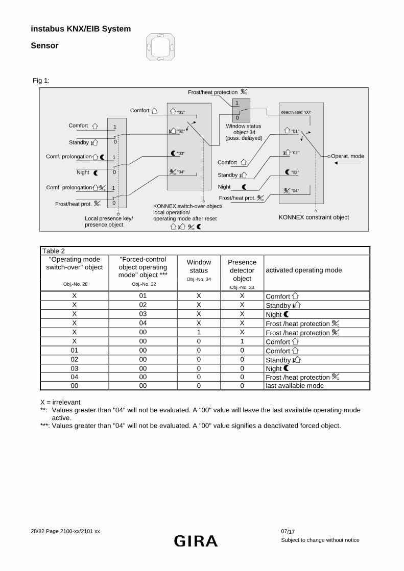
Taking into account the priorities there is the following switching hierarchy for an operating mode switch-over by objects, with a distinction being made between a presence detection via presence key (table 1 / figure 1) and by presence detector (table 2 / figure 2 on next page):
Table 1
"Operating mode switch-over" object
"Forced object operating mode"
object ***
Window status
Obj.-No. 34
Presence key object
Obj.-No. 33
activated operating mode
Obj.-No. 28 Obj.-No. 32 X 01 X X Comfort X 02 X X Standby X 03 X X Night X 04 X X Frost /heat protection X 00 1 X Frost /heat protection 01 00 0 0 Comfort 02 00 0 0 Standby 03 00 0 0 Night 04 00 0 0 Frost /heat protection 01 00 0 1 Comfort 02 00 0 1 Comfort 03 00 0 1 Comfort extension
04 00 0 1 Comfort extension 00 00 0 0 last available mode 00 00 0 1 Comfort / comfort mode
extension *
*: depends on the last available operating mode. / X = irrelevant **: Values greater than "04" will not be evaluated. A "00" value will leave the last available operating mode
active. ***: Values greater than "04" will not be evaluated. A "00" value signifies a deactivated forced object.
instabus KNX/EIB System
Sensor
28/82 Page 2100-xx/2101 xx 07/17
Subject to change without notice
Fig 1:
1
0Window status object 34
Comfort
1
0
1
0
1
0
Local presence key/presence object
Comf. prolongation
Night
Comf. prolongation
Frost/heat prot.
Comfort
Standby
KONNEX switch-over object/ local operation/operating mode after reset
Frost/heat protection
Operat. mode
KONNEX constraint object
deactivated "00"
"01"
"02"
"03"
"04"
Comfort
Standby
Night
Frost/heat prot.
"01"
"02"
"03"
"04"
(poss. delayed)
Table 2
"Operating mode switch-over" object
"Forced-control object operating mode" object ***
Window status
Obj.-No. 34
Presence detector object
Obj.-No. 33
activated operating mode
Obj.-No. 28 Obj.-No. 32
X 01 X X Comfort X 02 X X Standby X 03 X X Night X 04 X X Frost /heat protection X 00 1 X Frost /heat protection X 00 0 1 Comfort 01 00 0 0 Comfort 02 00 0 0 Standby 03 00 0 0 Night
04 00 0 0 Frost /heat protection 00 00 0 0 last available mode X = irrelevant **: Values greater than "04" will not be evaluated. A "00" value will leave the last available operating mode
active. ***: Values greater than "04" will not be evaluated. A "00" value signifies a deactivated forced object.

instabus KNX/EIB System
Sensor
07/17 2100-xx/2101 xx Page 29/82 Subject to change without notice
Fig 2:
1
0Window status object 34
Comfort
KONNEX switch-over object/ local operation/operating mode after reset
Frost/heat protection
Operat. mode
KONNEX constraint object
deactivated "00"
"01"
"02"
"03"
"04"
Comfort
Standby
Night
Frost/heat protection
"01"
"02"
"03"
"04"Frost/heat prot.
Standby
Night
Comfort
1
0Presence detector object object 33
(poss. delayed)
Notes for operating mode switch-over via "switching" (2 x 1-byte):
• Any operating mode switch-over will also update the KONNEX switch-over object and can be, if applicable, read out (set "read" flag!). If the "transmission" flag is set with this object, the current value will actively transmitted to the bus following a change. After a return of bus voltage or an initialization, the value corresponding to the adjusted operating mode will be actively transmitted on the bus if flag is set to "transmission". In case controller extensions are used, the "transmission" flag must also be set!
• When parameterizing a presence key: The presence object is active ("1") for the duration of an activated comfort mode extension. The presence object will automatically be deleted ("0"), if the comfort mode extension is terminated after the elapsed extension time, if the operating mode has been switched by a higher-priority control via the switch-over objects or local operation or if a forced operating mode has been deactivated via the KONNEX forced-control object (forced-control object "00").

instabus KNX/EIB System
Sensor
30/82 Page 2100-xx/2101 xx 07/17
Subject to change without notice
2.1.2 Notes on the operating modes
Presence function / comfort mode extension:
Via a presence detection the room temperature controller can switch into the comfort mode extension for a short time when a key is pressed or into the comfort mode if movement is detected. The "Presence detection" and "Type of presence detection" parameters on the "Room temperature controller function – functions" parameter page determine whether the presence detection is controlled by movement via the presence detector or manually by pressing the presence key: • Presence detection via presence key:
If the presence key is enabled as the type of presence detection, the setting "=Presence key" can be selected under key functions. In addition, the "Presence object" object 33 is enabled.
That way, it is possible to switch into the comfort mode extension during activated night mode or frost/heat protection (not activated via the "window status" object) by actuating the presence key or via a presence object value = "1". The extension is automatically deactivated as soon as the parameterized "Duration of comfort mode extension" has elapsed. A comfort mode extension can be prematurely deactivated, if the presence key is pressed again or if a value = "0" is received by the object. Retriggering of the extension time is not possible. If the duration of the comfort mode extension is set to "0", it will not be possible to activate a comfort mode extension from the night mode or the frost/heat protection. In this case, the operating mode is not changed even though the presence function is activated. If the standby mode is active, it is possible to switch into the comfort mode by actuating the presence key or via a presence object value = "1". This will also be the case, if the duration of the comfort mode extension is parameterized to "0". The active mode remains active for as long as the presence function is activated or until there is another operating mode.
The presence object or the presence function will always be deleted when switching over into another operating mode or after a forced-control operating mode has been deactivated (with KONNEX forced-control switch-over). The presence object is bi-directional ("W" and "T" flags set to default) so that an activation (= "1") or a deactivation (= "0") of the presence function will result in a transmission of telegrams with the corresponding object value. A presence function including the object that was activated before a reset will always be deleted after the reset.
• Presence detection by the presence detector:
If a presence detector is enabled for presence detection purposes, only the "Presence object" object 33 will be visible. This object can be used to incorporate presence detectors in the room temperature control. If any movement is detected ("1" telegram), the controller will switch into the comfort mode. The presettings by the switch-over objects or via local control directly on the touch sensor itself are not relevant. Only a window contact or the KONNEX forced-control object have a higher priority. After the delay time in the presence detector has elapsed ("0" telegram), the controller switches back into the mode which was active before the presence detection or it will track the telegrams of the switch-over objects received during the presence detection. Switching-over of the operating mode on the room temperature controller is not possible while the presence detection is active. A presence function that was activated before a reset will always be deleted after the reset. In this case the presence detector has to transmit a new "1" telegram in order to activate the presence function.

instabus KNX/EIB System
Sensor
07/17 2100-xx/2101 xx Page 31/82 Subject to change without notice
Window status:
The room temperature controller provides different ways of switching into the frost/heat protection . Besides switching by means of the corresponding operating mode switch-over object, the frost/heat protection can be activated by a window contact. Among these options, the window contact has the higher priority.
A telegram with the value = "1" (opened window) to object 34 will activate the frost/heat protection. In this case the operating mode cannot be deactivated by the operating mode switch-over objects (with the exception of the KONNEX forced-control object). Only a telegram with the value = "0" (closed window) will reset the window status and deactivate the frost/heat protection. Subsequently, the operating mode that was set before the opening of the window or tracked via the bus during the time the window was open will be activated.
Operating mode after reset:
In the ETS it is possible to determine via the "Operating mode after reset" parameter on the "Controller General" parameter page which operating mode is to be activated following a return of bus voltage or a programming operation with the ETS. The following settings are possible:
- "Comfort mode": After the initialization phase the comfort mode is activated.
- "Standby mode": After the initialization phase the standby mode is activated.
- "Night mode": After the initialization phase the night mode is activated.
- "Frost/heat protection": After the initialization phase the frost/heat protection is activated.
- Restore operating mode before reset": The mode that was activated before a reset will be readjusted after the initialization phase of the device.
The objects associated with the activated operating mode will be updated after a reset.

instabus KNX/EIB System
Sensor
32/82 Page 2100-xx/2101 xx 07/17
Subject to change without notice
2.1.3 Controller status
The room temperature controller is able to transmit its status. Available is either a general collective status report (1-byte) or alternatively one of up to 8 individual status reports (1-bit). The "Status controller" parameter on the "Actuating variable and status output" parameter page releases the status report and determines the status format: • "Status controller" = "controller general":
The 1-byte status object 36 includes the complete status information. The status - controlled by the control algorithm – is actively transmitted (cyclically every 30 seconds) to the bus (pre-condition: "T" flag is set!)The setting of the “R” flag allows the read-out of the status. Settings Relevance of data Controller general
1-byte Bit 0: 1: comfort mode active Bit 1: 1: standby mode active Bit 2: 1: night mode active Bit 3: 1: frost/heat protection active
Bit 4: 1: controller disabled Bit 5: 1: heating; 0: cooling Bit 6: 1: controller inactive (dead zone) Bit 7: 1: frost alarm (T room ≤ + 5 °C)
• "Status controller" = "Transmit individual status":
The 1-bit status object 36 includes the status information selected by the "Individual status" parameter. The status - controlled by the control algorithm – is actively transmitted (cyclically every 30 seconds) to the bus (pre-condition: "T" flag is set!)). The setting of the "R" flag allows the read-out of the status. Parameterization for
"Individual status" Relevance of data
Comfort mode active 1: comfort mode / extension active 0: no comfort mode Standby mode active 1: standby mode active 0: no standby mode Night mode active 1: Night mode active 0: no night mode Frost/ heat protection active 1: frost/heat protection active 0: no frost/heat protection Controller disabled 1: controller disabled (dew-point mode) 0: controller not disabled Heating/cooling 1: heating operation 0: cooling operation Controller inactive 1: controller inactive (dead zone) 0: controller active Frost alarm 1: frost alarm (T room ≤ + 5 °C) 0: no frost alarm (T room > + 5 °C) Meaning of status reports:
• Comfort operation: Active if the operating mode "comfort ' '" or a comfort mode extension " " or " " is activated.
• Standby operation: active if the "standby ' '" operating mode is activated. • Night-time operation: active if the "night-time ' '" operating mode is activated. • Frost/ heat protection: active if the "frost/heat protection ' '" operating mode is activated. • Controller disabled: active if controller disable is activated (dew-point mode). • Heating/cooling: active if the heating mode is activated and inactive if cooling mode is activated. (inactive
with controller disabled.) • Controller inactive: active with the "heating and cooling" control option when the measured room temperature
lies within the dead zone. This status information is always "0" for the individual "heating" or "cooling" control options! (inactive if controller is disabled.)
• Frost alarm: active if the detected room temperature reaches or drops below + 5 °C. The status report has no significant influence on the controller behaviour.
The status object 36 will be updated following a reset after the initialization phase. Afterwards the status is updated every 30 seconds parallel to the calculation of the controller’s actuating variable.

instabus KNX/EIB System
Sensor
07/17 2100-xx/2101 xx Page 33/82 Subject to change without notice
2.1.4 Additional controller status
The additional controller status is an object in which information already available on the bus is to be collected so that it can be displayed with a suitable device. This 1-byte object is a mere visualization object which does not allow any write access. This status object possesses a KNX-certified (but not standardized) datapoint type. Settings for "Controller
general" Relevance of data for "Additional controller status report"
Bit 0 1: normal operating mode 0: forced-control operating mode Bit 1 1: comfort extension active 0: no comfort extension Bit 2 1: presence (presence detector) 0: no presence (presence detector) Bit 3 1: presence (presence key) 0: no presence (presence key) Bit 4 1: window contact active 0: no window opened Bit 5 1: additional stage active 0: additional stage not active Bit 6 1: heat protection active
(heat protection temp. < actual temp.)
0: no heat protection (heat protection temp. > actual temp.)
Bit 7 1: controller disabled (dew-point mode) 0: controller not disabled The status object 57 will be updated following a reset after the initialization phase. Thereafter, the additional controller status is updated every 30 seconds parallel to the computation of the actuating variable of the controller. In the event of a change, the new status determined will be transmitted to the EIB.
instabus KNX/EIB System
Sensor
34/82 Page 2100-xx/2101 xx 07/17
Subject to change without notice
2.2 Control options and control option switch-over The room temperature controller features up to two control options. These control options determine whether the controller shall address heating systems (individual control option "heating") or cooling systems (individual control option "cooling") via its actuating variable. It is also possible to activate a mixed-mode in which the controller can switch-over automatically or, alternatively, object-controlled between "heating" and "cooling". Moreover, the control operation can be carried out in two stages for addressing an additional heating and cooling device. If controlled in two stages, actuating variables will be calculated separately for the basic and additional stage and transmitted on the bus depending on the deviation between actual and setpoint temperature. The "Control option" parameter on the "Controller General" parameter page determines the control option to be carried out and activates, if applicable, the additional stage(s). For the individual control options "heating" or "cooling" without additional stage, the controller runs with only one actuating variable. Alternatively, it runs with two actuating variables for the parameterized control option, if the additional stage is activated. Depending on the determined room temperature and the preset setpoint temperatures of the operating modes, the room temperature controller decides independently whether heating or cooling energy is required and calculates the actuating variable for the heating or cooling system. Following a reset (return of bus voltage or new ETS programming) in the "heating" or "cooling" mode, the controller will always operate in the control option that was set in the ETS. In the "heating and cooling" mixed-mode the controller is able to address heating and cooling systems. In this case, the switch-over behaviour of the control options can be preset:
• The "Switching-over between heating and cooling" parameter on parameter page "Controller functions" is set to "automatic":
Depending on the determined room temperature and the preset basic temperature setpoint value or the dead zone, the heating or cooling mode is automatically activated . If the room temperature lies within the preset dead zone, neither heating nor cooling will take place (both actuating variables = "0"). The room will be cooled down if the room temperature is higher than the temperature setpoint for cooling. The room will be heated up, if the room temperature is lower than the temperature setpoint for heating. With an automatic switch-over of the control option, the information can be actively transmitted to the bus via the "Control option switch-over" object 35. The "Automatic transmission heating/cooling switch-over" parameter determines when a control option switch-over is transmitted.
- Setting "Changing the control option": In this case, a telegram is transmitted solely when switching-over from heating to cooling (object value = "0") or from cooling to heating (object value = "1).
- Setting "Changing the output variable": With this setting, the current control option will always be transmitted if the output variable has changed. With the actuating variable = "0" the control option that was last active will be transmitted.
If the determined room temperature lies within the dead zone, the control option last activated will be retained in the object value until the controller is switched-over into the other control option.
With an automatic switch-over, the object value can also be transmitted cyclically. The "Cyclical heating/cooling switch-over" parameter enables cyclical transmission (factor setting > "0") and determines the cycle time.
Notes on the automatic switch-over of the control option:
A dead zone that is too narrow might result in continuous switching over between heating and cooling. For this reason the dead zone (temperature difference between the set-temperatures for heating and cooling comfort mode) should preferably not be adjusted below the default value.

instabus KNX/EIB System
Sensor
07/17 2100-xx/2101 xx Page 35/82 Subject to change without notice
• The "Switching-over between heating and cooling" parameter on parameter page "Controller functions" is set to "via object":
Independent of the dead zone, the control option is then controlled via the "Control option switch-over" object 35. This type of switch-over may be required, for example, in case of heating and cooling via a single-duct system (combined heating and cooling system). For this purpose, the temperature of the medium in the single-duct system must be changed beforehand by the system control. Afterwards, the control option is set via the object (often the single-duct system uses cold water for cooling during the summer, hot water for heating during the winter). The "Control option switch-over" object has the following polarity: "1": heating; "0": cooling. After a reset, the object value "0" and the "Control option heating/ cooling after reset" parameter will be activated. The "Control option heating / cooling after reset" parameter determines which control option will be activated after a reset. The "heating" or "cooling" setting causes the controller to activate the parameterized control option directly after the initialization phase. Setting the "Control option before reset" parameter will activate the control option that was selected before the reset. If a switch-over takes place via the control option object, the controller will first switch-over into a control option that was set after the reset. The controller will switch-over, if applicable, into the other control option only after the device has received an object update. Notes on the "control option before reset" setting:
• Frequent adjustments of the control options during ongoing operation (e.g. several times a day) may affect the product life of the device as in this case the non-volatile storage (EEPROM) is only designed for less frequent write access.
Heating / cooling message:
Depending on the selected control option it is possible to output the information via separate objects whether heating or cooling energy is currently required, i.e. whether heating or cooling operation is in progress. As long as the actuating variable for heating (cooling) is > "0", a "1" telegram is transmitted via the "heating" ("cooling") signalling object. The message telegrams will be reset only if the actuating variables = "0" ("0" telegram will be transmitted).
Exception: In case of a 2-state control, the LEDs "heating" or "cooling" will light up or the signalling objects for heating and cooling will already become active as soon as the temperature falls short of the temperature setpoint in case of heating or exceeds the temperature setpoint in case of cooling. In this case, the parameterized hysteresis is not being considered. Heating and cooling at the same time is not possible!
The signalling objects may be enabled via the "Heating message" or the "Cooling message" parameter on the "Actuating variable and status output" parameter page.
The signalling objects are controlled by the control algorithm. It has to be considered that the actuating variable is calculated only every 30 seconds (thus updating the signalling objects every 30 seconds).

instabus KNX/EIB System
Sensor
36/82 Page 2100-xx/2101 xx 07/17
Subject to change without notice
2.3 Room temperature control and actuating variables 2.3.1 Control algorithms, control circuits and calculation of actuating variable
A comfortable temperature control for a living space requires a special control algorithm which controls the installed heating or cooling systems. By considering the setpoint temperatures as well as the actual room temperature, the controller determines the actuating variables controlling the heating or cooling system. The control system (control circuit) consists of the room temperature controller, the servo drive or the switching actuator (for the use of electro-thermal drives), the actual heating or cooling element (e.g. heaters or cooling ceiling) and the room. This results in the following control process:
+-
Room temp. controller
Set valuetemperature
Control algorithm
Actuator/ ETA
Radiator/ cooling ceiling
RoomtemperatureRoom
Sun radiation,outside temperature, ...
The controller measures the actual temperature (determined room temperature) and compares it with the given setpoint temperature. The control algorithm calculates the actuating variable from the difference between actual and setpoint temperature. This enables the controller to compensate for actual/setpoint temperature differences in the control circuit caused by external influences (e.g. strong exposure to sun or varying outside temperatures) by regularly readjusting the actuating variable. In addition, the flow temperature of the heating and cooling circuit affects the control process making it necessary to adapt the actuating variables.
The room temperature controller allows the option between a continuous or switching proportional/integral control (PI) or a switching 2-state control.

instabus KNX/EIB System
Sensor
07/17 2100-xx/2101 xx Page 37/82 Subject to change without notice
The actuating variables calculated by the control algorithm are output via the "Actuating variable heating" or "Actuating variable cooling" communication objects. The control algorithm selected for the heating and/or cooling operation determines, among other things, also the format of the actuating variable object. Thus, it is possible to create 1-bit or 1-byte actuating variable objects.
The control algorithm is determined via the "Type of heating control" or "Type of cooling control" parameters on the "Controller general" parameter page, possibly also for the additional stages. Each of the following three algorithms can be selected:
1. Continuous PI control:
A PI control is an algorithm consisting of a proportional and an integral part. A combination of these control characteristics allows to accurately adjust the room temperature as fast as possible without or with only small control deviations.
This algorithm lets the room temperature controller calculate a new continuous actuating variable periodically every 30 seconds. This one will be output to the bus via a 1-byte value object, if the calculated actuating variable has changed by a predetermined percentage. The "Automatic transmission if value changes by..." parameter on the "Actuating variable and status output" parameter page determines the change interval in percent.
Variable (0 ... 100 %)
Time
Proportional part
Integral part
An additional PI controlled heating or cooling stage works exactly as the PI control of the basic stage. The difference is that the setpoint will shift by taking into account the parameterized stage offset. Characteristic feature of the PI control:
If the setpoint/actual value deviation of the room temperature results in an actuating variable of 100%, the room temperature controller uses the maximum actuating variable until the determined room temperature reaches the setpoint. This special control behaviour is known as 'clipping'. This will quickly heat up or cool down the temperature in chilled or overheated rooms. In two stage heating or cooling systems, this control behaviour also applies to the actuating variables of the additional stages.
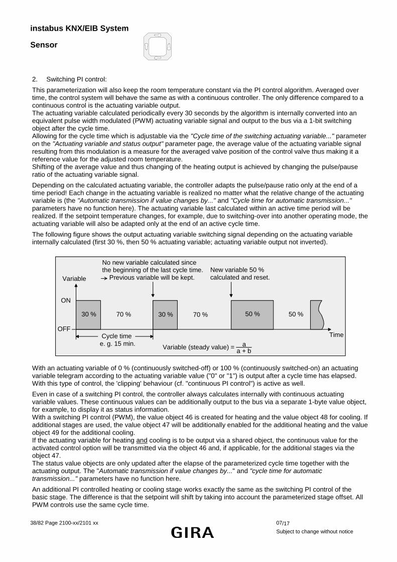
instabus KNX/EIB System
Sensor
38/82 Page 2100-xx/2101 xx 07/17
Subject to change without notice
2. Switching PI control:
This parameterization will also keep the room temperature constant via the PI control algorithm. Averaged over time, the control system will behave the same as with a continuous controller. The only difference compared to a continuous control is the actuating variable output. The actuating variable calculated periodically every 30 seconds by the algorithm is internally converted into an equivalent pulse width modulated (PWM) actuating variable signal and output to the bus via a 1-bit switching object after the cycle time. Allowing for the cycle time which is adjustable via the "Cycle time of the switching actuating variable..." parameter on the "Actuating variable and status output" parameter page, the average value of the actuating variable signal resulting from this modulation is a measure for the averaged valve position of the control valve thus making it a reference value for the adjusted room temperature. Shifting of the average value and thus changing of the heating output is achieved by changing the pulse/pause ratio of the actuating variable signal.
Depending on the calculated actuating variable, the controller adapts the pulse/pause ratio only at the end of a time period! Each change in the actuating variable is realized no matter what the relative change of the actuating variable is (the "Automatic transmission if value changes by..." and "Cycle time for automatic transmission..." parameters have no function here). The actuating variable last calculated within an active time period will be realized. If the setpoint temperature changes, for example, due to switching-over into another operating mode, the actuating variable will also be adapted only at the end of an active cycle time.
The following figure shows the output actuating variable switching signal depending on the actuating variable internally calculated (first 30 %, then 50 % actuating variable; actuating variable output not inverted).
Variable
ON
OFF Cycle time e. g. 15 min.
30 % 70 % 30 % 70 % 50 % 50 %
Time
New variable 50 % calculated and reset.
No new variable calculated sincethe beginning of the last cycle time. Previous variable will be kept.
Variable (steady value) = aa + b
With an actuating variable of 0 % (continuously switched-off) or 100 % (continuously switched-on) an actuating variable telegram according to the actuating variable value ("0" or "1") is output after a cycle time has elapsed. With this type of control, the 'clipping' behaviour (cf. "continuous PI control") is active as well.
Even in case of a switching PI control, the controller always calculates internally with continuous actuating variable values. These continuous values can be additionally output to the bus via a separate 1-byte value object, for example, to display it as status information. With a switching PI control (PWM), the value object 46 is created for heating and the value object 48 for cooling. If additional stages are used, the value object 47 will be additionally enabled for the additional heating and the value object 49 for the additional cooling. If the actuating variable for heating and cooling is to be output via a shared object, the continuous value for the activated control option will be transmitted via the object 46 and, if applicable, for the additional stages via the object 47. The status value objects are only updated after the elapse of the parameterized cycle time together with the actuating output. The "Automatic transmission if value changes by..." and "cycle time for automatic transmission..." parameters have no function here.
An additional PI controlled heating or cooling stage works exactly the same as the switching PI control of the basic stage. The difference is that the setpoint will shift by taking into account the parameterized stage offset. All PWM controls use the same cycle time.

instabus KNX/EIB System
Sensor
07/17 2100-xx/2101 xx Page 39/82 Subject to change without notice
Cycle time:
In most cases, the pulse width modulated actuating variables are used to control electro-thermal drives. The room temperature controller transmits the switching actuating variable telegrams to a switching actuator (preferably with semi-conductor switching elements) which is connected to the drives.
Setting the cycle time for the PWM signal allows to adapt the control to the drives that are being used. The cycle time determines the switching frequency of the pulse modulated signal and allows the adaptation to the adjusting cycle times of the servo drive (traversing time the drive requires to adjust the valve from a completely closed position to a completely opened position). In addition to the adjusting cycle time the dead time (time during which the servo drives show no response when switching on or off) has to be considered. If different drives with different adjusting cycle times are used, the longer time is to be considered. The manufacturer’s specifications for the drive have to be observed.
Two cases for the adjustment of the cycle time can be considered: I. Cycle time 2 x adjusting cycle time of the drives being used, for example 15 minutes (default)
In this case, the pulse/pause times of the PWM signal are long enough for the drives to completely open or close within a time period.
Advantages: The desired average value for the actuating variable and thus the required room temperature is relatively accurately adjusted even with several drives that are simultaneously activated.
Disadvantages: It has to be considered that - due to the constantly 'travelled' full valve lift - the product life of the drives may decrease. The heat transfer to the room in the vicinity of the heater may be non-uniform and may be felt bothering to some people if the cycle times are very long ( > 15 minutes) and if the system has a slower response (for example in case of smaller hot water heaters). Notes:
• This setting for the cycle time is recommended for slower, more inert heating systems (for example underfloor heating).
• This setting is also recommended for a larger number of possibly different drives making it easier to average the valve travel.
II. Cycle time > adjusting cycle time of the drives being used, for example 2 minutes (default)
In this case, the short pulse/pause times of the PWM signal are not sufficient for the drives to completely open or close within a time period.
Advantages: This setting ensures a constant water flow through the heaters with a uniform heat transfer to the room. If only one servo drive is controlled, the controller is able to compensate for the shift of the average value caused by the short cycle time by continuously adapting the actuating variable and is thus able to adjust the desired room temperature.
Disadvantages: If more than one drive is controlled at the same time, the desired average for the actuating variable and thus the required room temperature is adjusted only very poorly or with larger deviations. Important:
• This setting for the cycle time is recommended for fast-responding heating systems (for example hot water heaters with higher flow temperature).

instabus KNX/EIB System
Sensor
40/82 Page 2100-xx/2101 xx 07/17
Subject to change without notice
3. Switching 2-state control:
The 2-state control represents a very simple temperature control. For this type of control, two hysteresis temperature values are predefined. The controller addresses the actuating elements via switch-on and switch-off actuating variable commands (1-bit). A continuous actuating variable will not be calculated with this type of control. The room temperature is evaluated periodically every 30 seconds as well, i.e. the actuating variables, if required, will change only during these times. While the 2-state temperature control is very simple, the fluctuating temperature is a disadvantage. For this reason, no fast responding heating or cooling systems should be controlled via a 2-state control as it may result in very strong temperature overshoot and thus in a loss of comfort.
When defining the hysteresis limit settings, one has to distinguish between the control options: • Individual control options "heating" or "cooling":
While in heating mode the controller will switch-on the heater , if the temperature falls below a preset limit. In the heating mode the controller will switch-off the heater only, if an adjusted temperature limit has been exceeded. In the cooling mode the controller will switch-on the cooling, if the room temperature has exceeded a preset limit. While in the cooling mode, the controller will switch-off the cooling only if the temperature has fallen below an adjusted temperature limit. Depending on the switching state of the actuating variable, a "1" or "0" will be output, if the value exceeds or remains under the hysteresis limits. In case of a 2-step control, the LEDs "heating" or "cooling" will light up or the signalling objects for heating and cooling will already become active as soon as the temperature falls short of the temperature setpoint in case of heating or exceeds the temperature setpoint in case of cooling. In this case, the hysteresis is not being considered. The upper and lower hysteresis limits are to be parameterized in the ETS for both control options.
The following figure shows a 2-state control for the individual control options "heating" or "cooling” (heating on the left, cooling on the right; two temperature setpoints; one-stage heating or cooling; non-inverted actuating variable output):
Room temperature
Setpt. temp. 1
Setpt. temp. 2
ON
OFFTime
Room temperature
Setpt. temp. 1
Setpt. temp. 2
ON
OFFTime
Heating Cooling
Variable Variable TimeTime
An additional 2-state control heating or cooling stage works in exactly the same way as the 2-state control of the basic stage. The difference is that the setpoint and the hysteresis values will shift by taking into account the parameterized stage offset.
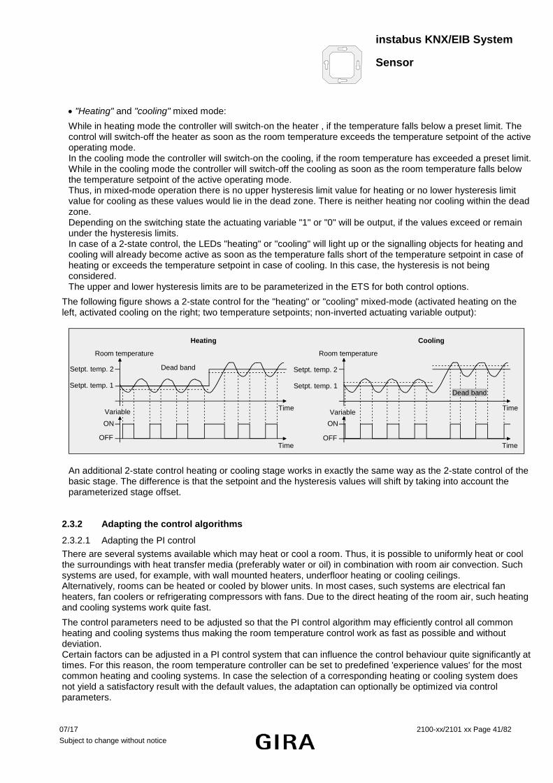
instabus KNX/EIB System
Sensor
07/17 2100-xx/2101 xx Page 41/82 Subject to change without notice
• "Heating" and "cooling" mixed mode:
While in heating mode the controller will switch-on the heater , if the temperature falls below a preset limit. The control will switch-off the heater as soon as the room temperature exceeds the temperature setpoint of the active operating mode. In the cooling mode the controller will switch-on the cooling, if the room temperature has exceeded a preset limit. While in the cooling mode the controller will switch-off the cooling as soon as the room temperature falls below the temperature setpoint of the active operating mode. Thus, in mixed-mode operation there is no upper hysteresis limit value for heating or no lower hysteresis limit value for cooling as these values would lie in the dead zone. There is neither heating nor cooling within the dead zone. Depending on the switching state the actuating variable "1" or "0" will be output, if the values exceed or remain under the hysteresis limits. In case of a 2-state control, the LEDs "heating" or "cooling" will light up or the signalling objects for heating and cooling will already become active as soon as the temperature falls short of the temperature setpoint in case of heating or exceeds the temperature setpoint in case of cooling. In this case, the hysteresis is not being considered. The upper and lower hysteresis limits are to be parameterized in the ETS for both control options.
The following figure shows a 2-state control for the "heating" or "cooling” mixed-mode (activated heating on the left, activated cooling on the right; two temperature setpoints; non-inverted actuating variable output):
Room temperature
Setpt. temp. 1
Setpt. temp. 2
Time
ON
OFFTime
Room temperature
Setpt. temp. 1
Setpt. temp. 2
ON
OFFTime
Heating Cooling
Dead band
Variable Variable
Dead band
Time
An additional 2-state control heating or cooling stage works in exactly the same way as the 2-state control of the basic stage. The difference is that the setpoint and the hysteresis values will shift by taking into account the parameterized stage offset.
2.3.2 Adapting the control algorithms
2.3.2.1 Adapting the PI control There are several systems available which may heat or cool a room. Thus, it is possible to uniformly heat or cool the surroundings with heat transfer media (preferably water or oil) in combination with room air convection. Such systems are used, for example, with wall mounted heaters, underfloor heating or cooling ceilings. Alternatively, rooms can be heated or cooled by blower units. In most cases, such systems are electrical fan heaters, fan coolers or refrigerating compressors with fans. Due to the direct heating of the room air, such heating and cooling systems work quite fast.
The control parameters need to be adjusted so that the PI control algorithm may efficiently control all common heating and cooling systems thus making the room temperature control work as fast as possible and without deviation. Certain factors can be adjusted in a PI control system that can influence the control behaviour quite significantly at times. For this reason, the room temperature controller can be set to predefined 'experience values' for the most common heating and cooling systems. In case the selection of a corresponding heating or cooling system does not yield a satisfactory result with the default values, the adaptation can optionally be optimized via control parameters.

instabus KNX/EIB System
Sensor
42/82 Page 2100-xx/2101 xx 07/17
Subject to change without notice
Predefined control parameters for the heating or cooling stage and, if applicable, also for the additional stages are adjusted via the "Type of heating" or "Type of cooling" parameters These fixed values correspond to the practical values of a properly planned and executed air conditioning system and will result in an ideal behaviour of the temperature control. The following types can be set for heating or cooling.
for heating control
Type of heating default values recommended recommended
Proportional range Reset-time type of PI control: PWM cycle time • Hot-water heating 5 Kelvin 150 minutes continuous / PWM 15 minutes ** • Underfloor heating 5 Kelvin 240 minutes PWM 15 – 20 min. • Electrical heating 4 Kelvin 100 minutes PWM 10 – 15 min. • Blower convector 4 Kelvin 90 minutes continuous --- • Split-unit * 4 Kelvin 90 minutes PWM 10 – 15 min. for cooling control
Type of cooling default values recommended recommended
Proportional range Reset-time type of PI control: PWM cycle time • Cooling ceiling 5 Kelvin 240 minutes PWM 15 – 20 min. • Blower convector 4 Kelvin 90 minutes continuous --- • Split-unit * 4 Kelvin 90 minutes PWM 10 – 15 min.
*: split mobile climate control unit, **: for smaller, fast-working heaters (e.g. higher flow temperature) PWM cycle time 2 – 3 minutes.
If the "Type of heating" or "Type of cooling" parameters are set to "via control parameters" it will be possible to adjust the control parameters manually. The control may be considerably influenced by presetting the proportional range for heating or for cooling ('P' part) and the reset-time for heating or for cooling ('I' part). Notes:
• Even minor adjustments of the control parameters will lead to a noticeably different control behaviour.
The adaptation should start with the control parameter setting for the corresponding heating or cooling system according to the fixed values mentioned above.
Variable
tTN
2 K xd
K xd (Proportional part)
y = K xd [1 + (t / TN)]
PI control algorithm: Actuating variable y = K x d [1 + (t / TN)]; By deactivating the reset-time (setting = "0"):
P control algorithm: Actuating variable y = K x d Parameter setting Effect P small proportional range large overshoot in case of setpoint changes (possibly permanently), quick
adjustment to the setpoint
P large proportional range no (or small) overshoot but slow adjustment T N short reset-time fast compensation of control deviations (ambient conditions), risk of
permanent oscillations
T N long reset-time slow compensation of control deviations
x d : Regeldifferenz x d = x soll - x ist P = 1/K : parametrierbarer Proportionalbereich K = 1/P : Verstärkungsfaktor T N : parametrierbare Nachstellzeit
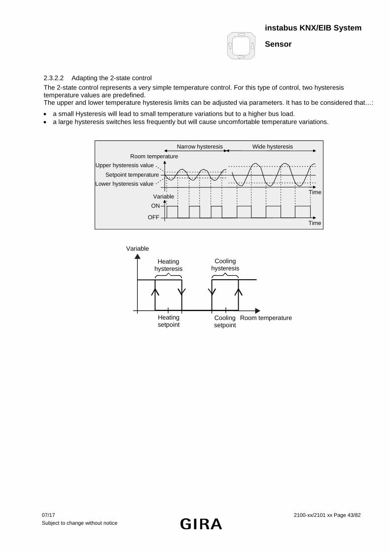
instabus KNX/EIB System
Sensor
07/17 2100-xx/2101 xx Page 43/82 Subject to change without notice
2.3.2.2 Adapting the 2-state control The 2-state control represents a very simple temperature control. For this type of control, two hysteresis temperature values are predefined. The upper and lower temperature hysteresis limits can be adjusted via parameters. It has to be considered that…:
• a small Hysteresis will lead to small temperature variations but to a higher bus load. • a large hysteresis switches less frequently but will cause uncomfortable temperature variations.
Room temperature
Setpoint temperature
ON
OFF
Variable
Time
Time
Upper hysteresis value
Lower hysteresis value
Narrow hysteresis Wide hysteresis
Variable
Room temperatureHeatingsetpoint
Cooling setpoint
Heatinghysteresis
Coolinghysteresis

instabus KNX/EIB System
Sensor
44/82 Page 2100-xx/2101 xx 07/17
Subject to change without notice
2.3.3 Actuating variable output
2.3.3.1 Actuating variable objects The format of the actuating variable objects is determined depending on the control algorithm selected for heating and / or cooling and, if applicable, also for the additional stages. 1-bit or 1-byte actuating variable objects can be created. The control algorithm calculates and outputs the actuating variables in intervals of 30 seconds. With the pulse-width modulated PI control (PWM), the actuating variable is updated, if required, only at the end of a time cycle. Possible object data formats for the actuating variables separately for both control options, for the basic and the additional stage, are…
• the continuous PI control: 1 byte, • the switching PI control: 1 bit + additionally 1 byte (e.g. for status indication in visualization systems), • the switching 2-state control: 1 bit. Depending on the selected control option, the controller is able to address heating and / or cooling systems, to determine actuating variables and to output them via separate objects. One distinguishes between two cases for the mixed mode "heating and cooling:
Case 1: Heating and cooling system are two separate systems. In this case, the "Transmit actuating variable heating and cooling to a shared object" parameter should be set to "no" (default) on the "Controller general" parameter page. Thus there are separate objects available for each actuating variable which can be separately addressed via the individual systems. This setting allows to define separate types of control for heating and cooling.
Case 2: Heating and cooling system are a combined system. In this case the "Transmit actuating variable heating and cooling to a shared object" parameter may be set, if required, to "yes" on the "Controller general" parameter page. This will transmit the actuating variables for heating and cooling to the same object. In case of a two-stage control, another shared object will be enabled for the additional stages for heating and cooling. With this setting, it is only possible to define the same type of control for heating and for cooling as the control and the data format must be identical. The ("Type of heating / cooling") control parameter for cooling and heating still have to be defined separately. A combined actuating variable object may be required, for example, if heating as well as cooling shall take place via a single-duct system (combined heating and cooling system). For this purpose, the temperature of the medium in the single-duct system must be changed beforehand by the system control. Afterwards the control option is set via the object (often the single-duct system uses cold water for cooling during the summer, hot water for heating during the winter).
Important:
Basically, it is not possible to heat and cool at the same time (actuating variables > "0")! If required, the actuating variable can be inverted before the transmission. The actuating variable value will be output in inverted form according to the object data format via the "Output of actuating variable heating" or "Output of actuating variable cooling" parameters or via a combined "Output of actuating variable" object . The parameter for inverting the additional stage(s) are additionally available in the two-stage controlled operation. The following applies…
for continuous actuating variables: not inverted: Actuating variable 0 % ... 100 %, Value 0 … 255, inverted: Actuating variable 0 % ... 100 %, Value 255 … 0, for switching actuating variables: not inverted: Actuating variable on / off, Value 0 / 1, inverted: Actuating variable on / off, Value 1 / 0.

instabus KNX/EIB System
Sensor
07/17 2100-xx/2101 xx Page 45/82 Subject to change without notice
2.3.3.2 Automatic transmission • Continuous PI control: In case of a continuous PI control the room temperature controller calculates a new actuating variable periodically every 30 seconds and outputs them to the bus via a 1-byte value object. The change interval of the actuating variable can be determined in percent according to which a new actuating variable is to be output on the bus via the "Automatic transmission if value changes by..." parameter on the "Actuating variables and status output" parameter page . The change interval can be parameterized to "0" so that a change in the actuating variable will not result in an automatic transmission.
In addition to the actuating variable output following a change, the current actuating variable value can be periodically transmitted to the bus. In addition to the times when changes are to be expected, other actuating variable telegrams will be output according to the active value after a parameterizable cycle time. This ensures that telegrams can be received within the monitoring interval during periodic safety monitoring of the actuating variable in the servo drive or in the addressed switching actuator. The time interval predetermined by the "Cycle time for automatic transmission..." parameter should correspond to the monitoring interval in the actuator (cycle time in the controller is preferably to be parameterized smaller). The "0" setting will deactivate the periodic transmission of the actuating variable.
With the continuous PI control it should be noted that - if periodic and automatic transmission are both deactivated - no more actuating variable telegrams will be transmitted in case of a change!
• Switching PI control PWM): In case of a switching PI control (PWM), the room temperature controller calculates a new actuating variable internally every 30 seconds. With this type of control, however, updating of the actuating variable takes place, if required, only at the end of a cycle. The "Automatic transmission if value changes by..." and "Cycle time for automatic transmission..." parameters are not enabled with this control algorithm.
• 2-state control: In case of a 2-state control, the room temperature and thus the hysteresis values are evaluated periodically every 30 seconds, so that the actuating variables, if required, will change only during these times. The "Automatic transmission if value changes by..." parameter is not enabled as this control algorithm does not calculate continuous actuating variables.
In addition to the actuating variable output following a change, the current actuating variable value can be periodically transmitted to the bus. In addition to the times when changes are to be expected, other actuating variable telegrams will be output according to the active value after a parameterizable cycle time. This ensures that telegrams can be received within the monitoring interval during periodic safety monitoring of the actuating variable in the servo drive or in the addressed switching actuator. The time interval predetermined by the "Cycle time for automatic transmission..." parameter should correspond to the monitoring interval in the actuator (cycle time in the controller is preferably to be parameterized smaller). The "0" setting will deactivate the periodic transmission of the actuating variable.

instabus KNX/EIB System
Sensor
46/82 Page 2100-xx/2101 xx 07/17
Subject to change without notice
2.4 Temperature setpoints 2.4.1 Setpoint presettings in the ETS
Temperature setpoints can be preset independently for each operating mode. The setpoints for the "comfort ", "standby " und "night " modes can be parameterized in the ETS. If desired, the setpoint temperatures can be subsequently adjusted via object control. The "frost/heat protection " operating mode allows the separate parameterization of two temperature setpoints for heating (frost protection) and cooling (heat protection) only in the ETS.
When presetting the setpoint temperatures for comfort, standby and night mode, attention has to be paid to the fact that all setpoints depend on each other as all values are derived from the basic temperature (basic setpoint). The "Basic temperature after reset" parameter on the "Setpoints" parameter page determines the basic setpoint which is loaded when the device is programmed with the ETS. Taking into account the "Decreasing /increasing the setpoint temperature in standby mode" or "Decreasing/ increasing the setpoint temperature in night mode" parameters, the temperature setpoints for the standby and night mode are derived from this value depending on the heating or cooling control option. The dead zone will be additionally considered for the "heating and cooling" mode. In two stage control mode, all setpoint temperatures of the additional stage are derived from the setpoint temperatures of the basic stage. The setpoint temperatures of the additional stage are determined by subtracting the "stage offset" , which is parameterized in the ETS from the setpoints of the basic stage in heating mode or by adding the setpoints in cooling mode. If the temperature setpoints of the basic stage are changed by setting a new basic setpoint, the setpoint temperatures of the additional stage will be indirectly and automatically changed as well. Both stages will heat or cool with the same actuating variable at the same time when the setpoint difference is "0". Depending on the control option, the relationships described on the following pages have to be considered for the setpoint temperatures.

instabus KNX/EIB System
Sensor
07/17 2100-xx/2101 xx Page 47/82 Subject to change without notice
2.4.1.1 Setpoints for the "heating" control option
Comfort mode
Standbymode
Nightmode
Frost/heat prot.mode
Standbyheating
temp. decrease Nightheating
temp. decrease
Frost protectionsetpoint
Temperature
Comfort temp. = basic setpoint
Standby temperature
Night temp.
(Recommended setpoint temperatures)
The setpoint temperatures for comfort, standby and night mode exist for this control option. The frost protection temperature can be preset. The following applies:
Tstandby setpoint heating ≤ Tcomfort setpoint heating or Tnight setpoint heating ≤ Tcomfort setpoint heating
The standby and night setpoint temperatures are derived from the comfort setpoint temperature (basic setpoint) in line with the parameterized decrease-temperatures.
The frost protection is supposed to prevent the heating system from freezing. For this reason the frost protection temperature should be set to a smaller value than the night temperature for heating (default: +7 °C). In principle, however, it is possible to select frost protection temperature values between +7 °C and +40 °C. The possible range of values for a setpoint temperature lies between + 7.0 °C and + 99.9 °C for "heating" and is limited by the frost protection temperature in the lower range.
The stage offset parameterized in the ETS will be additionally considered in a two stage heating mode.
Comfortmode
Standbymode
Nightmode
Frost/heat prot.mode
Temperature
Standbyheating
temp. decr. Nightheating
temp. decrease
Frost protectionsetpoint
Basic stage comf. temp.
Basic stage standby temp.
Basic stage night temp.
SW
SW
SW
Additional stage comf. temp.
Additional stage standby temp.
Additional stage night temp.
SW: Step width parameterized in the ETS plug-in
Tcomfort setpoint additional stage heating ≤ Tcomfort setpoint basic stage heating / Tstandby setpoint additional stage heating ≤ Tstandby setpoint basic
stage heating
Tstandby setpoint heating ≤ Tcomfort setpoint heating or
Tcomfort setpoint additional stage heating ≤ Tcomfort setpoint basic stage heating / Tnight setpoint additional stage heating ≤ Tnight setpoint basic stage
heating
Tnight setpoint value heating ≤ Tcomfort setpoint heating

instabus KNX/EIB System
Sensor
48/82 Page 2100-xx/2101 xx 07/17
Subject to change without notice
2.4.1.2 Setpoints for the "cooling" control option
Standbycooling
temp. increase
Night cooling
temp. increase
Heat protectionsetpoint
Comfortmode
Standbymode
Nightmode
Frost/heat prot.mode
Temperature
Comfort temp.
Standby temp.
Night temp.
(Recommended setpoint temperatures)
The setpoint temperatures for comfort, standby and night mode exist for this control option. The heat protection temperature can be preset. The following applies:
Tcomfort setpoint value cooling ≤ Tstandby setpoint cooling or Tcomfort setpoint cooling ≤ Tnight setpoint cooling
The standby and night setpoint temperatures are derived from the comfort setpoint temperature (basic setpoint) in line with the parameterized increase-temperatures.
The heat protection is supposed to prevent the temperature from exceeding the maximum permissible room temperature in order to protect system components.
For this reason, the heat protection temperature should be set to a larger value than the night temperature (default: +35 °C). In principle, however, it is possible to select heat protection temperature values between +7 °C and +45 °C. The possible range of values for a set-temperature lies between - 99.9 °C and + 45.0 °C for "cooling" and is limited by the heat protection temperature in the upper range.
The stage offset parameterized in the ETS will be additionally considered in a two stage heating mode.
Standbycooling
temp. increase
Nightcooling
temp. increase
Heat protectionsetpoint
Comfortmode
Standbymode
Nightmode
Frost/heat prot.mode
Temperature
Basic stage comfort temp.
Basic stage standby temp.
Additional stage night temp.
SW
SW
SW
Additional stage comf. temp.
Additional stage standby temp.
Additional stage night temp.
SW : Step width parameterized in the ETS plug-in
Tcomfort setpoint basic stage cooling ≤ Tcomfort setpoint additional stage cooling / Tstandby setpoint basic stage cooling ≤ Tstandby setpoint additional
stage cooling
Tcomfort setpoint cooling ≤ Tstandby setpoint cooling or
Tcomfort setpoint basic stage cooling ≤ Tcomfort setpoint additional stage cooling / Tnight setpoint basic stage cooling ≤ Tnight setpoint additional stage
cooling
Tcomfort setpoint cooling ≤ Tnight setpoint cooling

instabus KNX/EIB System
Sensor
07/17 2100-xx/2101 xx Page 49/82 Subject to change without notice
2.4.1.3 Setpoint for the "heating and cooling" control option:
Standbycooling
temp. increase
Night cooling
temp. increase
Heat protectionsetpoint
Comfortmode
Standbymode
Nightmode
Frost/heat prot.mode
Standbyheating
temp. decrease Nightheating
temp. decrease
Frost protectionsetpoint
Dead band betweenheating and cooling /
symmetrical dead band
Temperature
Basic setpoint
Comfort temp.
Standby temp.
Night temp.
Comfort temp.
Standby temperature
Night temp.
Standbycooling
temp. increase
Nightcooling
temp. increase
Heat protectionsetpoint
Comfortmode
Standbymode
Nightmode
Frost/heat prot. mode
Standbyheating
temp. decrease Nightheating
temp. decrease
Frost protectionsetpoint
Dead band betweenheating and cooling /
asymmetrical dead band
Temperature
Comfort temp. = basic setpoint
Standby temp.
Night temp.
Comfort temp.
Standby temp.
Night temp.
(Recommended setpoint temperatures)
For this control option, the setpoint temperatures of both control options exist for comfort, standby and night mode as well as the dead zone. In addition, the frost protection and the heat protection temperatures can be preset. The following applies:
Tstandby setpoint heating ≤ Tcomfort setpoint heating ≤ Tcomfort setpoint cooling ≤ Tstandby setpoint cooling
or
Tnight setpoint heating ≤ Tcomfort setpoint heating ≤ Tcomfort setpoint cooling ≤ Tnight setpoint cooling
The setpoint temperatures for "Standby" and "Night" are derived from the comfort setpoint temperatures for heating or cooling. The temperature increase (for cooling) and the temperature decrease (for heating) of both operating modes can be preset in the ETS. The comfort temperatures themselves are derived from the dead zone and the basic setpoint.
The frost protection is supposed to prevent the heating system from freezing. For this reason, the frost protection temperature should be to a set smaller value than the night temperature for heating (default: +7 °C). In principle, however, it is possible to select frost protection temperature values between +7 °C and +40 °C. The heat protection is supposed to prevent the temperature from exceeding the maximum permissible room temperature in order to protect system components. For this reason the heat protection temperature should be set to a larger value than the night temperature for cooling (default: +35 °C). In principle, however, it is possible to select heat protection temperature values between +7 °C and +45 °C. The possible range of values for a setpoint temperature ("heating and cooling") lies between + 7 °C and + 45.0 °C and is limited by the frost protection temperature in the lower range and by the heat protection temperature in the upper range.

instabus KNX/EIB System
Sensor
50/82 Page 2100-xx/2101 xx 07/17
Subject to change without notice
The stage offset parameterized in the ETS will be additionally considered in a two stage heating or cooling mode.
Standbycooling
temp. increase
Nightcooling
temp. increase
Heat protectionsetpoint
Comfortmode
Standbymode
Nightmode
Frost/heat prot.mode
Standby heating
temp. decr. Nightheating
temp. decrease
Frost protectionsetpoint
Dead band betweenheating and cooling /
symmetrical dead band
Temperature
Basic stage comfort temp. = basic setpoint
Basic stage standby temp.
Basic stage night temp.
Basic stage comfort temp.
Basic stage standby temp.
Basic stage night temp.
SW
SW
SW
SW
SW
SW
Additional stage comf. temp.
Additional stage standby temp.
Additional stage night temp.
Additional stage comf. temp.
Additional stage standby temp.
Additional stage night temp.
SW : Step width parameterized in the ETS plug-in
Tcomfort setpoint additional heating ≤ Tcomfort setpoint basic heating ≤ Tcomfort setpoint basic cooling ≤ Tcomfort setpoint additional cooling Tstandby setpoint additional heating ≤ Tstandby setpoint basic heating ≤ Tstandby setpoint basic cooling ≤ Tstandby setpoint additional cooling
Tstandby setpoint heating ≤ Tcomfort setpoint heating ≤ Tcomfort setpoint cooling ≤ Tstandby setpoint cooling or
Tcomfort setpoint additional heating ≤ Tcomfort setpoint basic heating ≤ Tcomfort setpoint basic cooling ≤ Tcomfort setpoint additional cooling Tnight setpoint additional heating ≤ Tnight setpoint basic heating ≤ Tnight setpoint basic cooling ≤ Tnight setpoint additional cooling
Tnight setpoint heating ≤ Tcomfort setpoint heating ≤ Tcomfort setpoint cooling ≤ Tnight setpoint cooling

instabus KNX/EIB System
Sensor
07/17 2100-xx/2101 xx Page 51/82 Subject to change without notice
Dead zone:
The comfort setpoint temperatures for heating and cooling are derived from the basic setpoint in consideration of the adjusted dead zone. The dead zone (temperature zone for which there is neither heating nor cooling) is the difference between the comfort setpoint temperatures. The "Dead zone between heating and cooling", "Dead zone position" parameters as well as the "Basic temperature after reset" parameter are preset in the ETS. The following settings must be distinguished:
Dead zone = "symmetrical" (default): The dead zone preset in the ETS is divided into two parts at the basic setpoint. The comfort setpoint temperatures are derived directly from the basic setpoint resulting from the half dead zone. The following applies:
Tbasic setpoint – ½Tdead zone = Tcomfort setpoint heating or Tbasic setpoint + ½Tdead zone = Tcomfort setpoint cooling
Tcomfort setpoint cooling – Tcomfort setpoint heating = Tdead zone; Tcomfort setpoint cooling ≥ Tcomfort setpoint heating
Dead zone position = "asymmetrical": With this setting, the comfort setpoint temperature for heating equals the basic setpoint! The dead zone preset in the ETS takes only effect from the basic setpoint in the direction of comfort temperature for cooling. Thus the comfort setpoint temperature for cooling is derived directly from the comfort setpoint for heating. The following applies:
Tbasic setpoint = Tcomfort setpoint heating Tbasic setpoint + Tdead zone = Tcomfort setpoint cooling
Tcomfort setpoint cooling – Tcomfort setpoint heating = Tdead zone; Tcomfort setpoint cooling ≥ Tcomfort setpoint heating
Feedback of setpoint temperature within the dead zone: If the room temperature is within the preset dead zone, the temperature setpoint value last active for heating and cooling will be displayed via object 50 "Setpoint temperature". 2.4.2 Adjusting the setpoints
2.4.2.1 Adjusting basic temperature and setpoint temperatures for comfort, standby and night mode When presetting the setpoint temperatures for comfort, standby and night mode, attention has to be paid to the fact that all setpoints depend on each other as all values are derived from the basic temperature (basic setpoint). The "Basic temperature after reset" parameter on the "Setpoints" parameter page determines the basic setpoint which is loaded when the device is programmed with the ETS.
It is possible to change or adjust the setpoint temperatures 'later' via the "Basic setpoint" object. Any change must always be enabled in the ETS on the "Setpoints" parameter page.
In case the basic setpoint adjustment via the bus is disabled, object 26 will be hidden.

instabus KNX/EIB System
Sensor
52/82 Page 2100-xx/2101 xx 07/17
Subject to change without notice
Adjusting the basic setpoint / comfort temperature for heating:
It is only in the event of a basic setpoint change that two cases must be distinguished:
- Case 1: The basic setpoint change is permanently adopted, - Case 2: The basic setpoint change is adopted only temporarily (default).
Via the "Adopt basic temperature setpoint change permanently" parameter on the "Room temperature controller function /setpoints" parameter page, it is possible to determine whether the changed basic temperature value shall be stored in memory permanently ("yes") or only temporarily ("no").
Case 1:
If the basic temperature setpoint is changed, it will be permanently stored in the room temperature controller's EEPROM. The newly adjusted value will overwrite the basic setpoint temperature originally parameterized in the ETS! This is the only way to keep the changed basic setpoint even after switching-over the operating mode or after a reset. Notes:
• Frequent adjustments of the basic temperature (e.g. several times a day) can affect the product life of the device as the non-volatile storage (EEPROM) is designed only for less frequent write access.
• The stored basic setpoint will still be active after the return of bus voltage. The value of the object 26 or 27 is then however "0". The current basic setpoint can be read out only after an external object update (set "R" flag!).
Case 2:
The basic setpoint received via the object stays only temporarily active in the current operating mode. In case of a bus voltage failure or following a switch-over into another operating mode (e.g. comfort followed by standby), the basic setpoint received via the object will be discarded and replaced by the value which was originally parameterized in the ETS.
Adjusting the setpoints for standby mode, night mode and dead zone (comfort temperature for cooling):
Since the setpoint temperatures for the "standby" and "night" operating modes or the setpoints for the "cooling" control option are derived - in consideration of the increase, decrease or dead zone values that are parameterized in the ETS - from the basic setpoint temperature, these setpoint temperatures will shift linearly by the change of the basic setpoint value. 2.4.2.2 Basic setpoint shifting In addition to the setting of individual temperature setpoints by the ETS by the basic setpoint object, the user is able to shift the basic setpoint anytime with the control wheel within the parameterized limits. It has to be considered that a shift of the setpoint temperature (temperature offset of the basic temperature) will directly affect the basic setpoint and as a result shift all other temperature setpoints. In general, shifting of the basic setpoint affects all operating modes. The shift is maintained even after switching-over the operating mode or the control option or after readjusting the basic setpoint. The adjustable temperature range for a basic setpoint shift is defined via the "Adjusting the basic setpoint temperature upwards" or "Adjusting the basic setpoint temperature downwards" parameters. It is possible to shift the current setpoint by a maximum of +/- 10 K. The stage offset is set to a non-adjustable 0.5 °C. Notes on the basic setpoint shifting:
• A setpoint shift does not affect the temperature setpoints for frost or heat protection.

instabus KNX/EIB System
Sensor
07/17 2100-xx/2101 xx Page 53/82 Subject to change without notice
Communication objects for the basic setpoint shifting: The controller tracks the current setpoint shift in the communication object 52 ("Current setpoint shifting") with a 1-byte counting value (acc. to KNX DPT 6.010 – representation of positive and negative values in a 2's complement). By connecting to this object the controller extensions are also able to display the current setpoint shift.
As soon as there is an adjustment by one temperature step (0.5 °C) in positive direction, the controller counts up the value by one digit. The counting value will be counted down by one digit, if there is a negative adjustment of the temperature. Thus the possible range of values for the object is determined by the setpoint’s adjustment options. A value of "0" means that no setpoint shift has been adjusted. Example:
Initial situation: The temperature step for the setpoint shift is set to 0.5 °K.
Current setpoint temperature = 21.0°C / counting value in object 52 = "0" (no setpoint shift active )
After shifting the setpoint: - A setpoint shift by one temperature step in positive direction will count up the value in object 52 by one = "1".
Current setpoint temperature = 21.5°C. - Another setpoint shift by one temperature step in positive direction will count up the value in object 52 again by
one = "2.. Current setpoint temperature = 22.0°C. - A setpoint shift by one temperature step in negative direction will count down the value in object 52 by one =
"1". Current setpoint temperature = 21.5°C. - Another setpoint shift by one temperature step in negative direction will count down the value in object 52
again by one = "0". Current setpoint temperature = 21.0°C. - Another setpoint shift by one temperature step in negative direction will count down the value in object 52
again by one = "-1". Current setpoint temperature = 20.5°C. etc. The maximum possible range of values for the "Current setpoint shift" communication object depends on the "Adjustment options of the basic setpoint temperature upwards/downwards" parameter. A parameterization of ± 10 K at this point will have the value of the object move within the limits –20 ... +20. In addition, the setpoint shift of the controller can be externally adjusted via communication object 53 ("Setpoint shift preset"). This object has the same datapoint type and range of values as object 52 (see above). By connecting to object 53, the controller extensions are able to directly adjust the current setpoint shift of the controller.
As soon as the controller receives a value, it will adjust the setpoint shift accordingly. Each value increment corresponds to a temperature step of 0.5°C (cf. example above). Values that lie within the possible range of values can be approached directly.
The controller monitors the received value independently. As soon as the external preset value exceeds the limits of the adjustment options for the setpoint shift in positive or negative direction, the controller will correct the received value and adjust the setpoint shift to maximum shift. Depending on the direction of the shift, the value feedback is set to the maximum value via communication object 52 ("Current setpoint shift"). Effect of the control wheel in conjunction with the external setpoint shift preset: An external setpoint shift (preset, for instance, at a controller extension) overrides a temperature shift last adjusted on the controller with the control wheel. The opposite case is equally valid: a change of the control wheel position overrides an externally preset setpoint shift. Thus, the value of the feedback via communication object 52 ("Current setpoint shift") always corresponds to the shift last performed.

instabus KNX/EIB System
Sensor
54/82 Page 2100-xx/2101 xx 07/17
Subject to change without notice
2.4.3 Transmitting the setpoint temperature
The setpoint temperature determined by the current operating mode or subsequently readjusted can be transmitted actively to the bus by means of object 50 "Setpoint temperature". The "Transmission when setpoint temperature changes by..." parameter on the "Room temperature controller functions – setpoints" parameter page determines the temperature value by which the setpoint has to change in order to have the setpoint temperature value transmitted automatically via the object. Temperature value changes between 0.1 C and 25.5°C or 0.1 K and 25.5 K are possible. A setting of "0" at this point will deactivate the automatic transmission of the set temperature. In addition, the setpoint can be transmitted cyclically. The "Cyclical transmission of room temperature" parameter determines the cycle time (1 to 255 minutes). The value "0" (default) will deactivate the cyclical transmission of the setpoint temperature. It should be noted that in case of deactivated cyclical transmission and deactivated automatic transmission, no setpoint temperature telegrams will be transmitted anymore.
Setting the "R" flag on the "Setpoint temperature" object makes it possible to read out the current setpoint. After return of bus voltage or new programming via the ETS, the object value will be updated according to the current setpoint temperature value and actively transmitted on the bus. 2.5 Room temperature measurement The room temperature controller measures the actual temperature cyclically and compares it with the given setpoint temperature. The control algorithm calculates the adjusted actuating variable from the difference between actual and set-temperature. In order to always ensure a fault-free and effective room temperature control, it is very important to determine the exact actual temperature.
The room temperature controller features an intergrated temperature sensor. Alternatively (e.g. if the room temperature controller has been installed in an unfavourable location or operates in difficult conditions, for example, in a moist atmosphere) or additionally (e.g. in large rooms or halls), a second KNX/EIB temperature sensor externally coupled via the bus or an external sensor at channel 4 of the pushbutton interface can be used to determine the actual value. When choosing the installation location of the controller or the external sensor, the following points should be considered:
• The controller sensor should not be used in multiple combinations, especially together with flush-mounted dimmers in the same combination.
• The sensors should not be installed in the vicinity of large electrical consumers (heat radiation). • The sensor should not be installed in the vicinity of heaters or cooling systems. • The temperature sensor should not be exposed to direct sun. • The installation of sensors on the inside of an outside wall might have a negative impact on the temperature
measurement. • Temperature sensors should be installed at least 30 cm away from doors or windows and at least 1.5 m above
the floor.

instabus KNX/EIB System
Sensor
07/17 2100-xx/2101 xx Page 55/82 Subject to change without notice
2.5.1 Temperature detection and determination of measured value
The "Temperature detection" parameter on the "Room temperature controller function – room temperature measurement" parameter page will determine which one of the sensors is used for sensing the actual temperature. The following settings are possible:
• "Internal sensor": The temperature sensor integrated in the room temperature controller is activated. Thus, the actual temperature is determined only locally on the device. When parameterized as such, the control will start directly after a reset.
• "External sensor": The actual temperature is determined only by the external temperature sensor. The internal sensor is deactivated. The external sensor must transmit the detected temperature value to the room temperature controller's 2-byte "External temperature sensor" (DPT-ID 9.001) object 24 . Alternatively or additionally, the room temperature controller can cyclically request the current temperature value (set "R" flag for the external sensor). For this purpose, the "Interrogation interval for external sensor..." parameter has to be set to a value > “0”. The interrogation interval can be set from 1 minute to 255 minutes. This parameterization will cause the room temperature controller to wait for a temperature value telegram from the external temperature sensor after a reset until the control starts and an actuating variable, if applicable, is output.
• "Internal and external sensor": With this setting, the internal as well as the external temperature sensor is active. The external sensor must transmit the detected temperature value to the room temperature controller's 2-byte "External temperature sensor" (DPT-ID 9.001) object 24 . Alternatively or additionally, the room temperature controller can cyclically request the current temperature value (set "R" flag for the external sensor). For this purpose, the "Interrogation interval for external sensor..." parameter has to be set to a value > “0”. The interrogation interval can be set from 1 minute to 255 minutes. This parameterization will cause the room temperature controller to wait for a temperature value telegram from the external temperature sensor after a reset until the control starts and an actuating variable, if applicable, is output.
The actual-temperature is made up from the two measured temperature values. The weighting of the temperature values is determined by the "Calculation of temperature based on internal / external measurement" parameter. Depending on the different locations of the sensors or a possible non-uniform heat distribution inside the room, it is thus possible to adjust the actual temperature measurement. Often, those temperature sensors that are subject to negative external influences (for example, unfavourable location because of exposure to sun or heater or door / window directly next to it) are weighted less heavily.
Example: Room temperature controller installed next to the entrance door (internal sensor). An additional external temperature sensor is installed on an inner wall in the middle of the room below the ceiling.
Internal sensor: 21.5°C (measuring range of internal sensor: 0 C … + 40°C ±1%) External sensor: 22.3 °C Calculation of temperature: 30% to 70 %
Result: Tresult internal = T intern ⋅ 0.3 = 6.45°C, Tresult external = T external = 22.3 °C ⋅0.7 = 15.61 C
Tresult actual = Tresult intern + Tresult extern = 22.06 C Note: If a temperature sensor is connected to channel 4 of the pushbutton interface and if the function "External temperature sensor for the controller" is selected on parameter page "Pushbutton interface – General", the measured values of this sensor will be written automatically into the controller's communication object. To prevent malfunctions, no other values must be written into this communication object via a group address. The parameter "Interrogation interval for external sensor" is then without function.

instabus KNX/EIB System
Sensor
56/82 Page 2100-xx/2101 xx 07/17
Subject to change without notice
2.5.2 Calibrating the measured values
In some cases it may be required to calibrate the temperature measurements of the internal and external sensor. A calibration becomes necessary, if the temperature measured by the sensors stays permanently below or above the actual room temperature in the vicinity of the sensor. The actual room temperature should be determined by a reference measurement with a calibrated temperature measuring device.
The "Calibration of internal sensor..." or "Calibration of external sensor..." parameter on the "Room temperature controller function –room temperature measurement" parameter page allows to parameterize the positive temperature adjustment (increase, factors: 1…127) or the negative adjustment (temperature decrease: factors – 128…-1) in 0.1°C increments. Thus, the calibration is made only once and is the same for all operating modes.
Important: • The measured value has to be increased, if the value measured by the sensor lies below the actual room
temperature. The measured value has to be decreased, if the value measured by the sensor lies above the actual room temperature.
• When the measured values from internal and external sensor are used, the actual value is calculated on the basis of the adjusted value. 2.5.3 Transmitting the actual temperature
The measured actual temperature can be actively transmitted to the bus via the "Actual temperature" object 23. The "Transmission when setpoint temperature changes by..." parameter on the "Room temperature controller functions –room temperature measurement" parameter page determines the temperature value by which the actual value has to change in order to have the actual temperature value transmitted automatically via the object 23. Temperature value changes between 0.1 C and 25.5°C or 0.1 K and 25.5 K are possible. A setting of "0" at this point will deactivate the automatic transmission of the actual temperature. In addition, the actual value can be transmitted cyclically. The "Cyclical transmission of room temperature" parameter determines the cycle time (1 to 255 minutes). The value "0" (default) deactivates the cyclical transmission of the actual temperature value. Setting the "R" flag on the "Actual temperature" object makes it possible to read out the current actual value. It should be noted that in case of deactivated cyclical transmission and deactivated automatic transmission, no setpoint temperature telegrams will be transmitted anymore.
After return of bus voltage or after new programming with the ETS, the object value will be updated according to the actual temperature value and transmitted to the bus. If no temperature value telegram has as yet been received from the external sensor when such an external KNX/EIB sensor is used, only the value provided by the internal sensor will be transmitted. If only the external sensor is used, the value "0" will be in the object after a reset. For this reason, the external KNX/EIB temperature sensor should always transmit the current value after a reset.
instabus KNX/EIB System
Sensor
07/17 2100-xx/2101 xx Page 57/82 Subject to change without notice
2.6 Disable functions of the room temperature controller 2.6.1 Disabling the control function
In certain operating conditions it may be required to deactivate the room temperature control. For example, the control can be switched-off during the dew-point mode of a cooling system or during maintenance work on the heating or cooling system.
The "Switch-off controller (dew-point mode)" parameter on the "Controller functions" parameter page enables the "Disable controller" object 40 when set to "via object". In addition, the controller disable function can be permanently deactivated when set to "no" (default). If a "1" telegram is received via the enabled disable object, the room temperature control is completely deactivated. In this case all actuating variables = "0" and the "dew-point operation" LED is lit up (wait for 30 s actuating variable update interval). The controller, however, can be operated in this case. In the two-stage heating or cooling mode, the additional stage can be separately disabled. The "Disable object additional stage" parameter on the "Controller general" parameter page will enable the "Disable additional stage" object 41 when set to "yes". In addition, the disable function of the additional stage can be permanently deactivated when set to "no" (default). In case a "1" telegram is received via the enabled disable object, the room temperature control is completely deactivated by the additional stage. The actuating variable of the additional stage is "0" while the basic stage continues to operate. A disable is always deleted after a reset (return of bus voltage, ETS programming operation). 2.7 Valve protection A valve protection may be carried out periodically in order to prevent the addressed control valves of the heater or cooling system to become calcified or stuck. The "Valve protection" parameter on the "Controller functions" parameter page will activate the valve protection when set to "yes". This type of protection is generally started not only for non-active actuating variable outputs, i.e. for outputs which have not requested any heating or cooling energy over the past 24 hours. For these outputs, the controller will periodically set the actuating variable to the maximum value once a day for a duration of approx. 5 minutes based on the following parameterization: Actuating variable output not inverted: 1-bit actuating variable: "1", 1-byte actuating variable: "255", Actuating variable inverted: 1-bit actuating variable: "0", 1-byte actuating variable: "0".
Thus, even valves closed for prolonged periods will be shortly opened on a regular basis. After a reset of the controller (ETS programming operation or bus voltage return), the 24-hour counter is automatically set to zero and restarted.

instabus KNX/EIB System
Sensor
58/82 Page 2100-xx/2101 xx 07/17
Subject to change without notice
3 Pushbutton interface functions The pushbutton interface features four channels which can be put to different uses.
- All four inputs allow the connection of potential-free contacts. In this case, the channels work as binary inputs.
- Channel 4 can also be used for connection of an NTC which can then optionally be used as an external temperature sensor for room temperature controller or as a temperature limiter for an underfloor heating.
- Channels 1 and 2 can also be used as outputs. In this case, they can control LEDs. 3.1 Binary input functions If a channel is used as binary input, it can be optionally configured as having no function, for switching, for dimming, for blind/shutter control or as value transmitter. If configured as "value transmitter", the following functions: "dimming value transmitter", "light-scene extension without storage function", "light-scene extension with storage function", "temperature value transmitter" and "brightness value transmitter" are moreover available. 3.1.1 "No function"
If the input function is parameterized for "no function", the pertaining objects are deactivated. 3.1.2 "Switching" function
If the input function is parameterized for "switching", the parameters "Command on rising edge" and "Command on falling edge" are visible for two separate switching objects in each case. Executable switching commands may include "ON", "OFF" or "TOGGLE". In case of "TOGGLE", the value which is stored in the switching object will be switched and transmitted. In addition, the transmission of a switching command can be suppressed (setting "no reaction"). 3.1.3 "Dimming" function
If the input function is parameterized for "dimming", several parameters for the dimming function as well as the "switching" and "dimming" objects will become visible. The parameter "Control" determines whether this channel is used alone (one-surface control) or in combination with another channel (two-surface control) and defines the switching and dimming commands that are output to the bus after a key-press. Executable switching commands may include "Darker (OFF)", "Brighter (ON)" or "TOGGLE". With the "Darker (OFF)" command, a short key-press will trigger an OFF telegram, a long key-press will trigger a dimming telegram (darker). With the "Brighter (ON)" command, a short key-press will trigger an ON telegram, a long key-press will trigger a dimming telegram (brighter). With the "TOGGLE" command, a short key-press will change the switching state internally stored in the switching object. If the stored state is ON (OFF), an OFF (ON) telegram will be triggered. A long key-press will transmit a "darker" telegram followed by a "brighter" telegram and vice versa. In addition, the dimming step width for "increasing and decreasing brightness" and the time "between switching and dimming" can be adjusted. A "stop telegram" can also be released at the end of a dimming operation (telegram transmission when releasing the key). If the "Telegram repetition" parameter is set to "yes", dimming telegrams can be cyclically transmitted during a key-press. The "Time between two dimming telegrams" is adjustable. A new dimming telegram is issued with the parameterized dimming step width every time the period ends.

instabus KNX/EIB System
Sensor
07/17 2100-xx/2101 xx Page 59/82 Subject to change without notice
3.1.4 "Blind/shutter" function
If the input function is parameterized for "Blind/shutter", several parameters for the blind/shutter function as well as the "Short-time operation" and "Long-time operation" objects will be visible. The "Operating concept" parameter predefines the telegram sequence for short and long-time telegrams that are transmitted with or during a key-press. - Short – Long - Short":
T1 T2
Release = STEP No actionSTEP MOVE
Press
Pressing the key will transmit a step command and time T1 is started ("Time between short and long-time operation"). If the key is released within T1, no further telegram will be transmitted. This STEP serves the purpose of stopping a continuous move.
If the key is pressed for more than T1, a MOVE command is automatically transmitted after T1 has elapsed while time T2 ("slat adjustment time") is started. If the key is released again within T2, the binary input will transmit a STEP telegram. This function is used for the adjustment of the slats. T2 should correspond to the time needed for a slat rotation through 180°. - Long - Short":
T1
Release = STEP No actionMOVE
Press
Pressing a key will transmit a MOVE command and time T1 is started ("slat adjustment time"). If the key is released again within T1, the binary input will transmit a STEP telegram. This function is used for the adjustment of the slats. T1 should correspond to the time needed for a slat rotation through 180°. The "Command on rising edge" parameter determines the polarity of the telegrams for long or short-time operation, i.e. their activated direction depending on the actuated (left or right) key. Executable commands may include "UP", "DOWN" or "TOGGLE". Important: A special role is played by the "TOGGLE" key function. For example, in the operation concept: • Step – Move – Step
(on a press of the key, the blind is to move visibly in the direction of the MOVE, before the step-move time has elapsed) - toggling takes place at every move - every step is executed in a direction opposite the one of the last move - several successive steps have the same direction
• Move – Step
- after a move telegram, the step object value of the step telegram is adapted to the move object value.

instabus KNX/EIB System
Sensor
60/82 Page 2100-xx/2101 xx 07/17
Subject to change without notice
3.1.5 "1-byte value transmitter" and 2-byte value transmitter" function
In the event of a value transmitter parameterization (value transmitter, temperature value transmitter or brightness value transmitter), the value to be transmitted can be changed by means of a long key-press (> 5 s) if the value is to be transmitted on the rising or the falling edge. In this case, the programmed value is increased by the parameterized step width and transmitted. After releasing of the contact at the input, the value last transmitted remains stored. On the next long key-press, the direction of value change is reversed. 1-byte dimming value transmitter example
Value (0...255) 17 Step width (1...10) 5
time
edge at input
value change
value variation direction change
5 s
timevalue = 17 17 17 2 0 0 2 7 12 17
time between two telegrams
no further value changeminimum value reached
> 5 s < 5 s
bustelegram
0 12 7
value change
Important:
- During value variation there is no overrun and no underrun. When the maximum (255) resp. the minimum (0) value is reached, no more telegrams are transmitted.
- To ensure that the concerned lighting switches off or on with the max. value during value variation, the limit values (values "0" resp. "255") are always transmitted when the limits of the variation range are reached. This is also the case when the parameterized step width does not directly account for these values (cf. example above: step width = 5; value "2" is transmitted, thereafter value "0"). To ensure that the original starting value can be set again during a new change (change of variation direction), the first value jump will not correspond to the preset step width (cf. example above: step width = 5; value "0" is transmitted, thereafter values "2", "7" etc.).
- When values are changed, the newly set values are stored in the RAM. After a bus voltage failure or a bus reset, the changed values will be replaced by the values originally parameterized in the ETS.

instabus KNX/EIB System
Sensor
07/17 2100-xx/2101 xx Page 61/82 Subject to change without notice
3.1.6 "Light-scene extension with / without storage" function
In a parameterization as light-scene extension without storage function it is possible to recall a light-scene. In case of a rising edge, a falling edge or a rising and a falling edge, the parameterized light-scene number is transmitted immediately.
In a parameterization as light-scene extension with storage function it is possible to generate a storage telegram depending on the light-scene to be transmitted. A long actuation of the n.o. contact (rising edge) or of the n.c. contact (falling edge) causes the corresponding storage telegram to be transmitted. In this case, the time for a long press is parameterizable (however not below 5 s). After a short press < 1 s, the parameterized light-scene number (without storage telegram) is transmitted. If the actuation is longer than 1 s, but shorter than 5 s, no telegram will be transmitted at all. In addition, it is possible to transmit only a storage telegram without preceding light-scene recall. In this case, the "Storage function only" parameter must be set to "YES". Examples for light-scene extension with storage function:
1.) storage function only = NO:
2.) storage function only = YES:
time
time
bustelegram
light-scene storage
storage
< 1 s 1 s to 3 s 5 s
edge at input
undefined input no telegram
light-scene recall
time
bustelegram
light-scene storage
light-scene storage
light-scene storage
light-scene storage
1.)
2.)
light-sene recall
storage function only = NO:
If a rising or a falling edge is detected at the input (depending on parameterization), the timer is started. If the key is released within the first second, the corresponding light-scene is recalled immediately. If the key is pressed longer, the storage telegram is transmitted after 5 s. storage function only = YES:
The storage telegram is transmitted immediately after detection of the corresponding edge.

instabus KNX/EIB System
Sensor
62/82 Page 2100-xx/2101 xx 07/17
Subject to change without notice
3.1.7 External temperature sensor
In combination with an NTC resistor, channel 4 can be used as external temperature sensor for the room temperature controller. Two parameters must be observed. At first, the parameter "Temperature detection" on the "Room temperature measurement" parameter page must be set to "external sensor" or to "internal and external sensor". Secondly, the function of channel 4 on parameter page "Pushbutton interface - General" must be observed. The measured values of the temperature sensor are then written automatically into communication object 24 "External temperature sensor". To prevent malfunctions, no other values must be written into this communication object via a group address. External temperature sensor examples:
Company Article no. / order no.: Gira 1493 00
3.1.8 Temperature limiter
If an underfloor heating is used, it may become necessary to limit the temperature inside the floor. The external temperature sensor at channel 4 can be used for purpose, too. When the parameter "Function of channel 4" on parameter page "Pushbutton interface - General" is set to "temperature limiter (underfloor heating)", the ETS will display three further parameters and a communication object. The parameter "Acting on..." is used to select whether the underfloor heating is controlled via the basic stage or the additional stage of the controller. The parameter "Limit temperature..." determines to which temperature the floor may be heated. As soon as this temperature is exceeded, the parameterized actuating variable output of the controller is internally set to "0". This prevents the temperature from rising any further. The parameter "Hysteresis..." determines how far the temperature must drop below the limit temperature until the actuating variable output is re-enabled. It should be noted that an unfavourable parameterization of the controller in this respect may influence the controller characteristics to such an extent that it will no longer be possible to reach the setpoint temperature. With communication object no. 3 "Floor temperature", the current temperature can be output.

instabus KNX/EIB System
Sensor
07/17 2100-xx/2101 xx Page 63/82 Subject to change without notice
3.1.9 Behaviour of the inputs on return of bus voltage
It is possible to specify separately for each input whether a reaction or what kind of reaction is to take place on return of bus voltage. Thus, a defined telegram can be transmitted to the bus depending on the input signal or by forced control. The defined reaction takes place only after the parameterized "Delay after bus voltage return" has elapsed. Within the delay, any signals or edges present on the inputs are not evaluated and disregarded. The delay is generally parameterized for all inputs and also for the outputs. It is possible to parameterize a general telegram rate limitation. In this case, no telegram is transmitted within the first 17 s after bus voltage return. It should be noted that the parameterized "Delay on return of bus voltage" is active also during this time and that the parameterized reaction on bus voltage return is not executed if the delay elapses within the first 17 seconds. 3.1.10 Input disable function
Each input can be independently configured for a certain reaction at the beginning or at the end of disable. It is also possible to parameterize the input for "No reaction". Only in this case will dimming or shutter control procedures or value changes in progress before activation of the disable function continue to be executed until the end when disable is active. In all other cases, the parameterized command will be transmitted immediately at the beginning of disable. Moreover, edges or signals at the corresponding inputs are not evaluated during an active disable. Updates on disable objects (disable or enable) will always lead to the transmission of the corresponding command parameterized for "the beginning resp. the end of disable". During an active disable, no cyclical transmission takes place via the disabled input. If cyclical transmission did take place before activation of the disable function, no cyclical transmission will take place anymore at the end of disable when "no reaction" is parameterized. In this case, the object value will again be transmitted cyclically only after an update on the switching object. In all other cases, the object value will again be transmitted cyclically after the end of disable. 3.1.11 Cyclical transmission
The object value transmitted is always the object value internally or externally tracked in the switching objects. For this reason, the object value is transmitted cyclically even if "no reaction" is assigned to a rising or a falling edge. Cyclical transmission takes place also directly after the return of bus voltage, if the parameterized value of the telegram after bus voltage return corresponds to the object value parameterization for cyclical transmission. If telegram rate limitation is enabled, cyclical transmission will occur at the earliest after 17 seconds. During an active disable, no cyclical transmission takes place via the disabled input.

instabus KNX/EIB System
Sensor
64/82 Page 2100-xx/2101 xx 07/17
Subject to change without notice
3.2 Description of output functions Channels 1 and 2 of the pushbutton interface can be parameterized as outputs. In this case, they are used to drive LEDs or electronic relays (current consumption < 0.8 mA at 5 V DC). To increase the overall current output (cf. technical data), both switching outputs can be connected in parallel if they have the same parameterization. The parameter "Output function" can be used to define the information to be provided by the output. The user can choose whether a 1-bit actuating variable of the controller or the value of an external switching object is to be output. If an actuating variable is to be output, the controller must either work as a two-stage controller or with pulse-width modulation. If the controller is used as a continuous PI controller with a 1-byte output, the output remains in the off state. If the output works with an external switching object, the ETS will indicate this state with object no. 4 or no. 5. In the event of a change of the switching status of an output, the current switching status is transmitted to the bus via the corresponding feedback object (no. 0 or no. 1). The feedback object value will be updated after the return of the bus voltage when the delay has elapsed and transmitted actively to the bus. With the telegram rate limitation enabled, no telegram will be transmitted via the feedback object within the first 17 s after return of bus voltage. The feedback message is stored and will be transmitted when the 17 s delay has elapsed. If applicable, the object status can be read out by a visualization software (set R-flag).

instabus KNX/EIB System
Sensor
07/17 2100-xx/2101 xx Page 65/82 Subject to change without notice
Parameters Description: Values: Remarks:
Controller general Control option
heating cooling heating and cooling basic and additional heating basic and additional cooling basic and additional heating and cooling
Setting of the control option
Only in two-stage heating or cooling mode Disable object additional stage
no
yes
The additional stages can be separately disabled via the bus. The parameter enables the disable object.
The additional stages cannot be separately disabled.
The additional stages cannot be separately disabled via the disable object.
Only with control options "heating and cooling" or "basic and additional heating and cooling" Transmit actuating variables for heating and cooling to shared object
no yes
If the parameter is set to "yes", the actuating variable will be transmitted to a shared object during heating or cooling. This function is used, if the same heating system is used to cool the room in the summer and used to heat the room in the winter.
Type of heating control (if applicable, for basic and additional stage)
continuous PI control switching PI control PWM) switching 2-state control (ON/OFF)
Selects a control algorithm (PI or 2-point) with data format (1-byte or 1-bit) for the heating system.
Only with continuous or switching PI control: Type of heating (if applicable, for basic and additional stage)
hot-water heating (5 K / 150 min) underfloor heating (5 K / 240min) electric heating (4 K / 100 min) fan convector (4 K / 90 min) split unit (4 K / 90 min) via control parameter
Adapts the PI algorithm to different heating systems using experience values for the proportional range and reset time control parameters. Separate input of control parameter.
Only with separate input of control parameter: Proportional range heating (10 … 127) * 0.1 K
10...127, 50 Separate setting of the "proportional range" control parameter.
Only if "type of heating" = "via control parameter".
Reset time heating (0 ... 255) * 1 min; 0 = inactive
0...250, 150 Separate setting of the "reset time" control parameter.
Only if "type of heating" = "via control parameter".
Only with switching 2-state control:

instabus KNX/EIB System
Sensor
66/82 Page 2100-xx/2101 xx 07/17
Subject to change without notice
Upper hysteresis of the 2-state controller heating (5 ... 127) * 0.1 K
5...127, 5 Definition of switch-on and switch-off temperatures for heating.
Only if "type of heating control" = "2-state".
Lower hysteresis of the 2-state controller heating (-128 ... –5) * 0.1 K
-128...-5, -5 Definition of switch-on and switch-off temperatures for heating.
Only if "type of heating control" = "2-state".
Type of cooling control (if applicable, for basic and additional stage)
Continuous PI control Switching PI control PWM) Switching 2-point control (ON/OFF)
Selects a control algorithm (PI or 2-state) with data format (1 byte or 1 bit) for the cooling system.
Only if "Transmit actuating variables for heating and cooling to shared object" = "no". If "Transmit actuating variables for heating and cooling to shared object" = "yes", the parameter settings for "Type of heating control" will be accepted.
Only with continuous or switching PI control: Type of cooling (if applicable, for basic and additional stage)
Cooling ceiling (5 K / 240 min) Fan convector (4 K / 90 min) Split unit (4 K / 90 min)
Via control parameter
Adapts the PI algorithm to different cooling systems using experience values for the proportional range and reset time control parameters.
Separate input of control parameter.
Only with separate input of control parameter: Proportional range cooling (10 ... 127) * 0.1 K
10...127, 50
Separate setting of the "proportional range" control parameter.
Only if "Type of cooling" = "via control parameter".
Reset time cooling (0 ... 255) * 1 min; 0 = inactive
0...255, 240 Separate setting of the "reset time" control parameter.
Only if "Type of cooling" = "via control parameter".
Only with switching 2-state control: Upper hysteresis of the 2-state controller cooling (5 ... 127) * 0.1 K
5...127, 5 Defines the switch-on and switch-off temperatures for cooling.
Only if "Type of cooling control" = "2-state".
Lower hysteresis of the 2-state controller cooling (-128 ... –5) * 0.1 K
-128...-5, -5 Defines the switch-on and switch-off temperatures for cooling
Only if "Type of cooling control" = "2-state".

instabus KNX/EIB System
Sensor
07/17 2100-xx/2101 xx Page 67/82 Subject to change without notice
Operating mode switch-over via value (1-byte)
Via switching (4 x 1-bit)
The switch-over of the operating modes via the bus takes place according to the KONNEX specification via a 1-byte value object. In addition, a higher-ranking forced-control object is available for this setting.
The 'classic' switch-over of the operating modes via the bus is via separate 1-bit objects.
Operating mode after reset Comfort mode standby mode Night mode Frost /heat protection
Defines the operating mode which is set, for instance after a reset caused by bus voltage return or by new programming.
Only with operating mode switch-over via 1-bit objects: Operating mode when all bit objects = 0 (preferred state)
Comfort mode standby mode Night mode Frost /heat protection last state before change to 0
Defines the operating mode which is activated when all 1-bit operating mode objects have value "0".
Setpoint values Basic temperature after reset (7 ... 4) * 1 °C
7.0 °C … + 40 °C, 21 °C Defines the basic setpoint value after the initialization.
Basic temperature setpoint change
deactivated permit via the bus
Determines whether an adjustment of the basic temperature possible via the bus.
Adopt basic temperature setpoint permanently
NO YES
This parameter determines whether the basic temperature value which has been adjusted via the bus is to be permanently (setting "yes") or only temporarily (setting "no") stored in memory.
When set to "yes" the changed basic value will be retained even after a switch-over of the operating mode and after a reset. Only if "Basic temperature setpoint change" = "permit via the bus"
Frost protection setpoint temperature (7...40) * 1 °C
7 °C … + 40 °C, 7 °C Defines the setpoint temperature with activated frost protection.
Only if "Control option" = "heating" or "heating and cooling", if applicable, with additional stage
Heat protection setpoint temperature (7...45) * 1 °C
7 °C … + 45 °C, 35 °C Defines the setpoint temperature with activated heat protection.
Only if "Control option" = "cooling" or "heating and cooling", if applicable, with additional stage.
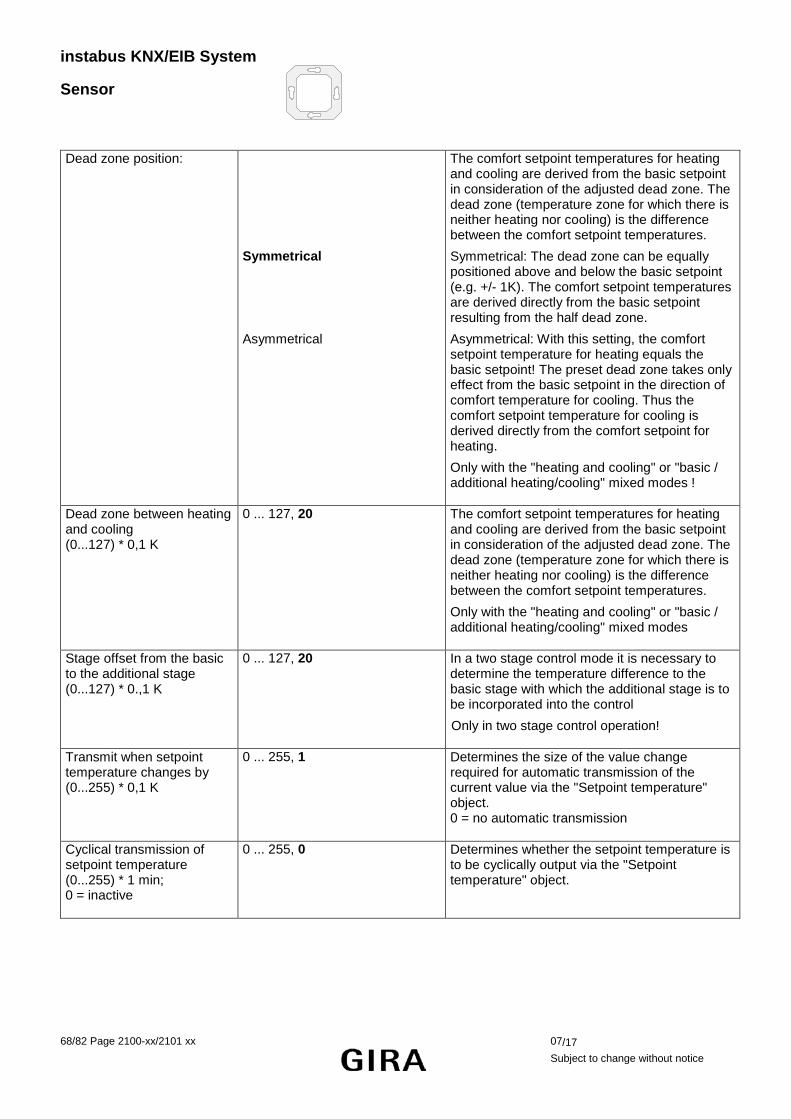
instabus KNX/EIB System
Sensor
68/82 Page 2100-xx/2101 xx 07/17
Subject to change without notice
Dead zone position:
Symmetrical
Asymmetrical
The comfort setpoint temperatures for heating and cooling are derived from the basic setpoint in consideration of the adjusted dead zone. The dead zone (temperature zone for which there is neither heating nor cooling) is the difference between the comfort setpoint temperatures.
Symmetrical: The dead zone can be equally positioned above and below the basic setpoint (e.g. +/- 1K). The comfort setpoint temperatures are derived directly from the basic setpoint resulting from the half dead zone.
Asymmetrical: With this setting, the comfort setpoint temperature for heating equals the basic setpoint! The preset dead zone takes only effect from the basic setpoint in the direction of comfort temperature for cooling. Thus the comfort setpoint temperature for cooling is derived directly from the comfort setpoint for heating.
Only with the "heating and cooling" or "basic / additional heating/cooling" mixed modes !
Dead zone between heating and cooling (0...127) * 0,1 K
0 ... 127, 20 The comfort setpoint temperatures for heating and cooling are derived from the basic setpoint in consideration of the adjusted dead zone. The dead zone (temperature zone for which there is neither heating nor cooling) is the difference between the comfort setpoint temperatures.
Only with the "heating and cooling" or "basic / additional heating/cooling" mixed modes
Stage offset from the basic to the additional stage (0...127) * 0.,1 K
0 ... 127, 20 In a two stage control mode it is necessary to determine the temperature difference to the basic stage with which the additional stage is to be incorporated into the control
Only in two stage control operation!
Transmit when setpoint temperature changes by (0...255) * 0,1 K
0 ... 255, 1 Determines the size of the value change required for automatic transmission of the current value via the "Setpoint temperature" object. 0 = no automatic transmission
Cyclical transmission of setpoint temperature (0...255) * 1 min; 0 = inactive
0 ... 255, 0 Determines whether the setpoint temperature is to be cyclically output via the "Setpoint temperature" object.

instabus KNX/EIB System
Sensor
07/17 2100-xx/2101 xx Page 69/82 Subject to change without notice
Adjustment of setpoint to higher temperatures
0 K +1 K +2 K +3 K +4 K +5 K +6 K +7 K +8 K +9 K +10 K
Determines the maximum adjustment range for the upward adjustment of the basic setpoint temperature.
(cf. "Basic temperature setpoint change" parameter)
Adjustment of setpoint to lower temperatures (-10...0) * 1 K
0 K -1 K -2 K -3 K -4 K -5 K -6 K -7 K -8 K -9 K -10 K
Determines the maximum adjustment range for the downward adjustment of the basic setpoint temperature.
(cf. "Basic temperature setpoint change" parameter)
Decreasing the setpoint temperature in standby mode (heating) (-128...0) * 0.1 K
-128 ... 0, -20 The value by which the standby setpoint temperature for heating is lowered compared to the basic setpoint.
Only if "Control option" = "heating" or "heating and cooling", if applicable, with additional stages.
Increasing the setpoint temperature in night mode (heating) (-128...0) * 0,1 K
-128 ... 0, -40 The value by which the night setpoint temperature for heating is lowered compared to the basic setpoint.
Only if "Control option" = "heating" or "heating and cooling", if applicable, with additional stages.
Decreasing the setpoint temperature in standby mode (cooling) (0...127) * 0.1 K
0 ... 127, 20 The value by which the standby setpoint temperature for cooling is lowered compared to the basic setpoint.
Only if "Control option" = "cooling" or "heating and cooling", if applicable, with additional stages.
Increasing the setpoint temperature in night mode (cooling) (0...127) * 0.1 K
0 ... 127, 40 The value by which the night set-temperature for cooling is lowered compared to the basic setpoint.
Only if "Control option" = "cooling" or "heating and cooling", if applicable, with additional stages.
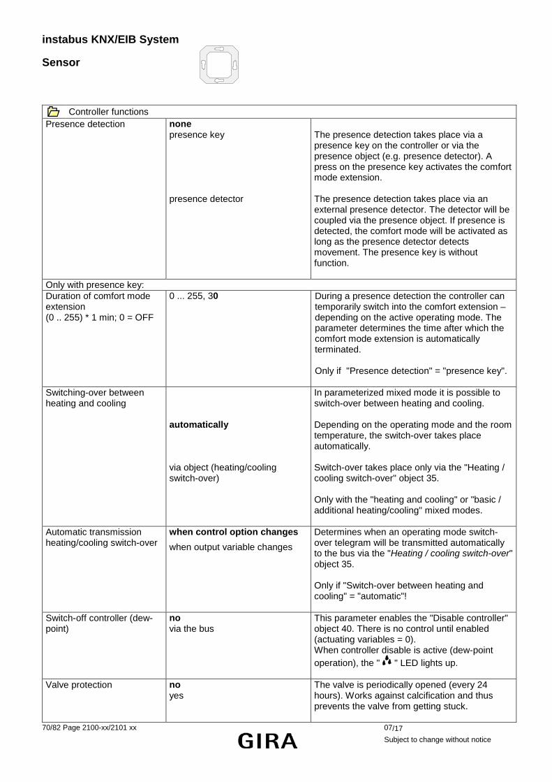
instabus KNX/EIB System
Sensor
70/82 Page 2100-xx/2101 xx 07/17
Subject to change without notice
Controller functions Presence detection none
presence key presence detector
The presence detection takes place via a presence key on the controller or via the presence object (e.g. presence detector). A press on the presence key activates the comfort mode extension. The presence detection takes place via an external presence detector. The detector will be coupled via the presence object. If presence is detected, the comfort mode will be activated as long as the presence detector detects movement. The presence key is without function.
Only with presence key: Duration of comfort mode extension (0 .. 255) * 1 min; 0 = OFF
0 ... 255, 30 During a presence detection the controller can temporarily switch into the comfort extension – depending on the active operating mode. The parameter determines the time after which the comfort mode extension is automatically terminated. Only if "Presence detection" = "presence key".
Switching-over between heating and cooling
automatically via object (heating/cooling switch-over)
In parameterized mixed mode it is possible to switch-over between heating and cooling. Depending on the operating mode and the room temperature, the switch-over takes place automatically. Switch-over takes place only via the "Heating / cooling switch-over" object 35. Only with the "heating and cooling" or "basic / additional heating/cooling" mixed modes.
Automatic transmission heating/cooling switch-over
when control option changes
when output variable changes Determines when an operating mode switch-over telegram will be transmitted automatically to the bus via the "Heating / cooling switch-over" object 35. Only if "Switch-over between heating and cooling" = "automatic"!
Switch-off controller (dew-point)
no via the bus
This parameter enables the "Disable controller" object 40. There is no control until enabled (actuating variables = 0). When controller disable is active (dew-point operation), the " " LED lights up.
Valve protection no yes
The valve is periodically opened (every 24 hours). Works against calcification and thus prevents the valve from getting stuck.

instabus KNX/EIB System
Sensor
07/17 2100-xx/2101 xx Page 71/82 Subject to change without notice
Room temperature measurement Temperature detection
internal sensor external sensor internal and external sensor
Determines which sensor will be used for room temperature measurement. Internal sensor: built-in sensor of the controller External sensor: an external sensor coupled via the bus, e.g. for severe measuring conditions (swimming pools or similar). Internal and external sensor: Both sensors are used, for example, in large rooms.
Determination of measured value from internal / external ratio
10% to 90 % 20% to 80 % 30% to 70 % 40% to 60 % 50% to 50 % 60% to 40 % 70% to 30 % 80% to 20 % 90% to 10 %
Determines the weighting of the measured temperature value for the internal and external sensors. That results in an overall value which will be used for the further evaluation of the room temperature.
Only if "Temperature detection" = "internal and external sensor"
Calibration of internal sensor (-128...127) * 0.1 K
-128 ... 127, 0 Determines the value by which the internal sensor’s room temperature value is calibrated.
Only if "Temperature detection" = "internal sensor" or "internal and external sensor".
Calibration of external sensor (-128...127) * 0.1 K
-128 ... 127, 0 Determines the value by which the external sensor’s room temperature value is calibrated.
Only if "Temperature detection" = "external sensor" or "internal and external sensor".
Interrogation interval for external sensor (0...255) * 1 min; 0 = inactive
0 ... 255, 0 Determines the interrogation interval for the external sensor’s temperature value .
0" = sensor transmits its temperature value automatically.
Only if "Temperature detection" = "external sensor" or "internal and external sensor".
Transmission when room temperature changes by (0..255) * 0,1 K; 0 = no automatic transmission
0 ... 255, 3 Determines the size of the value change of the room temperature after which the current values are automatically transmitted to the bus via "Actual temperature" object 23.
Cyclical transmission of room temperature (0...255) * 1 min; 0 = inactive
0 to 255, 15 Determines whether or when the determined room temperature is to be cyclically output via "Actual temperature" object 23.
Actuating variable and status output
instabus KNX/EIB System
Sensor
72/82 Page 2100-xx/2101 xx 07/17
Subject to change without notice
Automatic transmission if value changes by... (0...100) * 1 %; 0 = inactive
0 to 100, 3
Determines the size of the actuating variable change that will cause the automatic transmission of the continuous actuating variables via the actuating variable objects.
Only if at least one type of control is parameterized to "continuous PI control"!
Cycle time of switching variable (1...255) * 1 min
1 to 255, 15
Determines the cycle time for the pulse-width-modulated actuating variable (PWM).
Only if at least one type of control is parameterized to "switching PI control (PWM)".
Cycle time for automatic transmission (0...255) * 1 min; 0 = inactive
0 to 255, 10
Time interval for the cyclical transmission of the actuating variable via the actuating variable objects.
Only if at least one type of control is parameterized to "continuous PI control" or "switching 2-state control".
Output of actuating variable heating
inverted (closed when sourcing current)
normal (opened when sourcing current)
continuous: Act. var.= 100 % - normal act. var. switching: Act. var. = 1 - normal act. var.
normal actuating variable output heating
Only if "Control option" = "heating" or "heating and cooling".
Output of actuating variable basic stage heating
inverted (closed when sourcing current)
normal (opened when sourcing current)
continuous: Act. var. = 100 % - normal act. var. switching: Act. var. = 1 - normal act. var.
normal actuating variable output basic stage heating
Only if "control option= basic and additional heating" or "basic/additional heating/cooling".
Output of actuating variable additional stage heating
inverted (closed when sourcing current)
normal (opened when sourcing current)
continuous: Act. var. = 100 % - normal act.var. switching: Act. var. = 1 - normal act. var.
normal actuating variable output additional stage heating
Only if "Control option" = "basic and additional heating" or "basic/additional heating/cooling".
Output of actuating variable cooling
inverted (closed when sourcing current)
normal (opened when sourcing current)
continuous: Act. var. = 100 % - normal act. var. switching: Act. var. = 1 - normal act. var.
normal actuating variable output cooling
Only if "Control option" = "cooling" or "heating and cooling".
instabus KNX/EIB System
Sensor
07/17 2100-xx/2101 xx Page 73/82 Subject to change without notice
Output of actuating variable basic stage cooling
inverted (closed when sourcing current)
normal (opened when sourcing current)
continuous: Act. var. = 100 % - normal act. var. switching: Act. var. = 1 - normal act. var.
normal actuating variable output basic stage cooling
Only if "Control option" = "basic and additional cooling" or "basic/additional heating/cooling".
Output of actuating variable additional stage cooling
inverted (closed when sourcing current)
normal (opened when sourcing current)
continuous: Act. var. = 100 % - normal act. var. switching: Act. var. = 1 – normal act. var.
normal actuating variable output additional stage cooling
Only if "Control option" = "basic and additional cooling" or "basic/additional heating/cooling".
Heating message no yes
Enables the "heating" message function and thus the "Heating message" object 37.
Cooling message no yes
Enables the "cooling" message function and thus the "message cooling" object 38.
Controller status no status controller general transmitting individual status
The controller can output its current operating status. No status will be output. The controller status is generally output via the 1-byte object (object 36 "Controller status"). The controller status preset by the "Individual status" parameter will be output via the 1-bit object (Object 36 "Controller status").
Individual status comfort mode active standby mode active night mode active frost/heat protection active controller disabled heating/cooling controller inactive frost alarm
Defines the controller status to be transmitted. Only if "Controller status" = "transmit individual status".
Pushbutton interface - General Function of channel 1 binary input
output for electronic relay and LED
Channel 1 of the pushbutton interface can optionally be used as input for a potential-free contact or as output for an LED or an electronic relay.
Function of channel 2 binary input output for electronic relay and LED
Channel 2 of the pushbutton interface can optionally be used as input for a potential-free contact or as output for an LED or an electronic relay.
Function of channel 3 binary input
Channel 3 is always used as input for a potential-free contact.
instabus KNX/EIB System
Sensor
74/82 Page 2100-xx/2101 xx 07/17
Subject to change without notice
Function of channel 4 binary input input for temperature sensor temperature limiter (underfloor heating)
Channel 4 can optionally be used as input for a potential-free contact, as external temperature sensor of the room temperature controller or as temperature limiter for an underfloor heating. When used as temperature sensor, the parameter "Temperature detection" on parameter page "Room temperature measurement" must at the same time be set to "external sensor" or "internal and external sensor". When used as temperature limiter, the other settings are made on a separate parameter page.
Delay on return of bus voltage, base Delay on return of bus voltage, factor (3 … 127)
130 ms 260 ms 520 ms 1 s 2.1 s … 1.2 h 3 … 127, 17
For all channels of the pushbutton interface it is possible to define a common delay time during which no reactions take place or no telegrams are transmitted after return of bus voltage. The pushbutton interface begins to evaluate the separately parameterized reactions of the channels only after this delay has elapsed. If the delay time is less than 17 seconds and if the telegram rate limitation is additionally active, the defined behaviour of the channels on return of bus voltage will not be executed.
Debouncing time, (factor 10 … 255) (base = 0.5 ms)
10 … 255, 60 Depending on the quality of the contacts connected, this parameter can be used to define how long the contact must be actuated until the pushbutton interface detects a valid press.
Telegram rate limitation disabled enabled
If the telegram rate limitation is enabled, the pushbutton interface does not transmit telegrams in the first 17 seconds after bus voltage return.
Telegrams per 17 s 30 60 100 127
When the telegram rate limitation is activated, this parameter defines the maximum number of telegrams that can be transmitted.
When a channel (X = 1 to 4) of the pushbutton interface is used as binary input Input X
Function of input X no function switching dimming blind/shutter value transmitter
When used as binary input, the available settings are the same for all channels.

instabus KNX/EIB System
Sensor
07/17 2100-xx/2101 xx Page 75/82 Subject to change without notice
Only if function = switching Command on rising edge switching object X.1
no reaction ON OFF TOGGLE
Defines the command transmitted when a make-contact button is pressed.
Command on falling edge switching object X.1
no reaction ON OFF TOGGLE
Defines the command transmitted when a make-contact button is released.
Command on rising edge switching object X.2
no reaction ON OFF TOGGLE
Defines the command transmitted when a make-contact button is pressed.
Command on falling edge switching object X.2
no reaction ON OFF TOGGLE
Defines the command transmitted when a make-contact button is released.
Behaviour on return of bus voltage
no reaction transmission of ON telegram transmission of OFF telegram transmission of current input state
Defines whether and what kind of information will be transmitted after return of bus voltage
Cyclical transmission? no cyclical transmission repeat when ON repeat when OFF repeat when ON and OFF
Defines whether the telegrams are repeated in the event of sustained actuation.
Time base for cyclical transmission switching object X.1
1 s 2.1 s 4.2 s 8.4 s … 35 min no cyclical transmission via switching object X.1
Together with the common factor, this parameter defines the intervals within which the telegrams are repeated.
Time base for cyclical transmission switching object X.2
1 s 2.1 s 4.2 s 8.4 s … 35 min no cyclical transmission via switching object X.2
Together with the common factor, this parameter defines the intervals within which the telegrams are repeated.
Time factor for cyclical transmission switching object X.1 and X.2 (3…127)
3 … 127, 60
Together with the individual bases, this parameter defines the intervals within which the telegrams are repeated.

instabus KNX/EIB System
Sensor
76/82 Page 2100-xx/2101 xx 07/17
Subject to change without notice
Only if function = dimming Control one-surface control
darker/brighter (TOGGLE) two-surface control brighter (ON) two-surface control darker (OFF) two-surface control brighter (TOGGLE) two-surface control darker (TOGGLE)
Defines the reactions in case of a sustained or a brief press. A sustained press sends dimming telegrams whereas a brief press sends switching telegrams. With "brighter/darker" and with "TOGGLE", the internally stored state will be changed and transmitted on the next press.
Time between switching and dimming, base Time between switching and dimming, factor (4 … 127)
130 ms 260 ms 520 ms 1 s 4 … 127, 4
Time after which the function assigned to a long key-press (dimming) is executed.
Behaviour on return of bus voltage
no reaction transmission of ON telegram transmission of OFF telegram
Defines whether and what kind of information will be transmitted after return of bus voltage
Increase brightness by 100 % 50 % … 1.5 %
Determines the maximum step width of a dimming telegram. A dimming telegram can increase the brightness by X % maximum.
Reduce brightness by 100 % 50 % … 1.5 %
Determines the maximum step width of a dimming telegram. A dimming telegram can reduce the brightness by X % maximum.
Transmit stop telegram no yes
A release of the key transmits one or no stop telegram.
Telegram repetition no yes
Cyclical repetition of a dimming telegram during a key-press.
Time between two telegrams, base Time between two telegrams, factor (3 … 127)
130 ms 260 ms 520 ms 1 s 3 … 127, 10
Time between two telegrams when telegram repetition is selected. After this time, a new dimming telegram will be sent. Only if telegram repetition = "yes".
Only if function = blind/shutter Command on rising edge no function
UP DOWN TOGGLE
Defines the command transmitted when a make-contact button is pressed.
Behaviour on return of bus voltage
no reaction UP DOWN
Defines whether and what kind of information will be transmitted after return of bus voltage
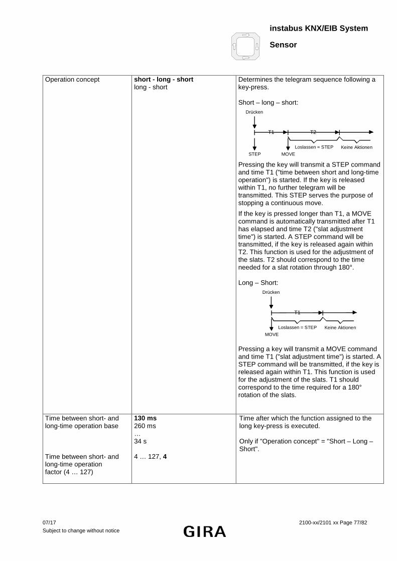
instabus KNX/EIB System
Sensor
07/17 2100-xx/2101 xx Page 77/82 Subject to change without notice
Operation concept short - long - short long - short
Determines the telegram sequence following a key-press. Short – long – short:
T1 T2
Loslassen = STEP Keine AktionenSTEP MOVE
Drücken
Pressing the key will transmit a STEP command and time T1 ("time between short and long-time operation") is started. If the key is released within T1, no further telegram will be transmitted. This STEP serves the purpose of stopping a continuous move.
If the key is pressed longer than T1, a MOVE command is automatically transmitted after T1 has elapsed and time T2 ("slat adjustment time") is started. A STEP command will be transmitted, if the key is released again within T2. This function is used for the adjustment of the slats. T2 should correspond to the time needed for a slat rotation through 180°. Long – Short:
T1
Loslassen = STEP Keine AktionenMOVE
Drücken
Pressing a key will transmit a MOVE command and time T1 ("slat adjustment time") is started. A STEP command will be transmitted, if the key is released again within T1. This function is used for the adjustment of the slats. T1 should correspond to the time required for a 180° rotation of the slats.
Time between short- and long-time operation base Time between short- and long-time operation factor (4 … 127)
130 ms 260 ms … 34 s 4 … 127, 4
Time after which the function assigned to the long key-press is executed. Only if "Operation concept" = "Short – Long – Short".

instabus KNX/EIB System
Sensor
78/82 Page 2100-xx/2101 xx 07/17
Subject to change without notice
Slat adjustment time base Slat adjustment time factor (3 … 127)
130 ms 260 ms … 34 s 3 … 127, 20
Time during which a transmitted MOVE telegram can be terminated by releasing the key (STEP). This function is used for adjusting the slats of a blind.
Only if function = value transmitter Function as dimming value transmitter
light-scene extension without storage function light-scene extension with storage function temperature value transmitter brightness value transmitter
When used as value transmitter, the settings for some applications are predefined.
Only with dimming value transmitter Transmit value on rising edge (key as make
contact) falling edge (key as break contact) rising and falling edge (switch)
Defines whether telegrams are to be transmitted when a key is pressed and / or released
Value on rising edge Value on falling edge
0 … 255, 100 0 … 255, 0
Defines the values transmitted after the above type of actuation.
Behaviour on return of bus voltage
no reaction reaction as with rising edge reaction as with falling edge transmission of current input state
Defines whether and what kind of information will be transmitted after return of bus voltage
Value adjustment by long press
NO YES
Pressing the key for at least 5 s will cause the current value to be cyclically reduced by the parameterized step width and to be transmitted. After release of the key, the previously transmitted value remains stored. This parameter defines whether a value adjustment is possible.
Time between two telegrams, base Time between two telegrams, factor (3 … 127)
130 ms 260 ms 520 ms 1 s 3 … 127, 3
Time between two telegrams when telegram repetition is selected. A new dimming telegram is transmitted whenever this time elapses. Only if "Value adjustment by long press" = "yes"
Step width (1 … 10) 1 … 10, 10 Step width by which the adjusted value is changed on a long key-press.

instabus KNX/EIB System
Sensor
07/17 2100-xx/2101 xx Page 79/82 Subject to change without notice
Only with light-scene extension without storage function Transmit light-scene number on...
rising edge (key as make contact) falling edge (key as break contact) rising and falling edge (switch)
Defines whether telegrams are to be transmitted when a key is pressed and / or released.
Light-scene on rising edge (1 … 64) Light-scene on falling edge (1 … 64)
1 … 64, 1 1 … 64, 1
Defines the values transmitted after the above type of actuation.
Behaviour on return of bus voltage
no reaction reaction as with rising edge reaction as with falling edge transmission of current input state
Defines whether and what kind of information will be transmitted after return of bus voltage
Only with light-scene extension with storage function Transmit light-scene number on...
rising edge (key as make contact) falling edge (key as break contact)
Defines whether telegrams are to be transmitted when a key is pressed and / or released.
Light-scene on rising edge (1 … 64) Light-scene on falling edge (1 … 64)
1 … 64, 1 1 … 64, 1
Defines the values transmitted after the above type of actuation.
Behaviour on return of bus voltage
no reaction reaction as with rising edge reaction as with falling edge transmission of current input state
Defines whether and what kind of information will be transmitted after return of bus voltage
Storage function only? NO YES
In the basic setting, the input distinguishes between a brief press (recall of the scene) and a long press (storage of the scene) If only the storage function is desired, a brief press alone is sufficient to store the scene.
Time of a long press for storage base Time of a long press for storage factor (9 … 127)
130 ms 260 ms 520 ms 1 s 9 … 127, 10
Defines the time the channel must be activated so that the telegram for scene storage will be transmitted. Depending on previous parameter.

instabus KNX/EIB System
Sensor
80/82 Page 2100-xx/2101 xx 07/17
Subject to change without notice
Only with temperature value transmitter Transmit value on rising edge (key as make
contact) falling edge (key as break contact) rising and falling edge (switch)
Defines whether telegrams are to be transmitted when a key is pressed and / or released.
Value on rising edge Value on falling edge
0 °C … 40 °C, 20 °C 0 °C … 40 °C, 18 °C
Defines the values transmitted after the above type of actuation.
Behaviour on return of bus voltage
no reaction reaction as with rising edge reaction as with falling edge transmission of current input state
Defines whether and what kind of information will be transmitted after return of bus voltage
Value change by long press NO YES
Pressing the key for at least 5 s will cause the current value to be cyclically reduced by the fixed step width (1 K) and to be transmitted. After releasing the key, the previously transmitted value remains stored. This parameter defines whether a value adjustment is possible.
Time between two telegrams base Time between two telegrams factor (3 … 127)
130 ms 260 ms 520 ms 1 s 3 … 127, 3
Time between two telegrams when telegram repetition is selected. A new dimming telegram is transmitted whenever this time elapses. Only if "Value adjustment by long press" = "yes"
Only with brightness value transmitter Transmit value on rising edge (key as make
contact) falling edge (key as break contact) rising and falling edge (switch)
Defines whether telegrams are to be transmitted when a key is pressed and / or released.
Value on rising edge Value on falling edge
0 lux, 50 lux, … 1500 lux, 200 lux 0 lux, 50 lux, … 1500 lux, 0 lux
Defines the values transmitted after the above type of actuation.
Behaviour on return of bus voltage
no reaction reaction as with rising edge reaction as with falling edge transmission of current input state
Defines whether and what kind of information will be transmitted after return of bus voltage
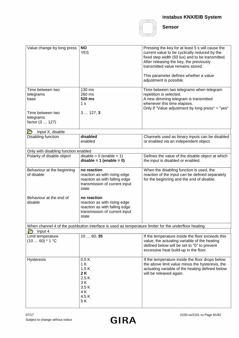
instabus KNX/EIB System
Sensor
07/17 2100-xx/2101 xx Page 81/82 Subject to change without notice
Value change by long press NO YES
Pressing the key for at least 5 s will cause the current value to be cyclically reduced by the fixed step width (50 lux) and to be transmitted. After releasing the key, the previously transmitted value remains stored. This parameter defines whether a value adjustment is possible.
Time between two telegrams base Time between two telegrams factor (3 … 127)
130 ms 260 ms 520 ms 1 s 3 … 127, 3
Time between two telegrams when telegram repetition is selected. A new dimming telegram is transmitted whenever this time elapses. Only if "Value adjustment by long press" = "yes"
Input X, disable Disabling function disabled
enabled Channels used as binary inputs can be disabled or enabled via an independent object.
Only with disabling function enabled Polarity of disable object disable = 0 (enable = 1)
disable = 1 (enable = 0) Defines the value of the disable object at which the input is disabled or enabled.
Behaviour at the beginning of disable Behaviour at the end of disable
no reaction reaction as with rising edge reaction as with falling edge transmission of current input state no reaction reaction as with rising edge reaction as with falling edge transmission of current input state
When the disabling function is used, the reaction of the input can be defined separately for the beginning and the end of disable.
When channel 4 of the pushbutton interface is used as temperature limiter for the underfloor heating Input 4
Limit temperature (10 … 60) * 1 °C
10 … 60, 35 If the temperature inside the floor exceeds this value, the actuating variable of the heating defined below will be set to "0" to prevent excessive heat build-up in the floor.
Hysteresis 0.5 K 1 K 1.5 K 2 K 2.5 K 3 K 3.5 K 4 K 4.5 K 5 K
If the temperature inside the floor drops below the above limit value minus the hysteresis, the actuating variable of the heating defined below will be released again.
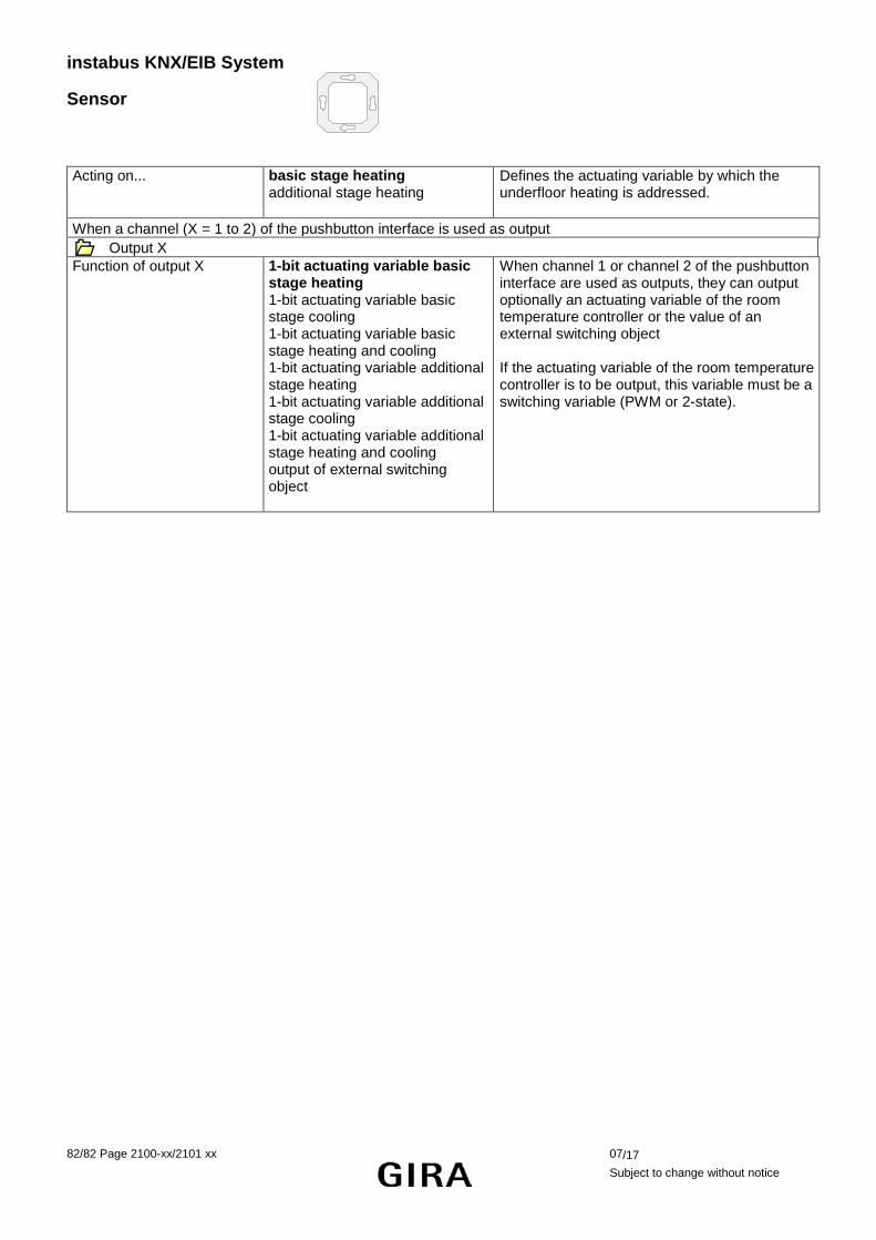
instabus KNX/EIB System
Sensor
82/82 Page 2100-xx/2101 xx 07/17
Subject to change without notice
Acting on... basic stage heating additional stage heating
Defines the actuating variable by which the underfloor heating is addressed.
When a channel (X = 1 to 2) of the pushbutton interface is used as output Output X
Function of output X 1-bit actuating variable basic stage heating 1-bit actuating variable basic stage cooling 1-bit actuating variable basic stage heating and cooling 1-bit actuating variable additional stage heating 1-bit actuating variable additional stage cooling 1-bit actuating variable additional stage heating and cooling output of external switching object
When channel 1 or channel 2 of the pushbutton interface are used as outputs, they can output optionally an actuating variable of the room temperature controller or the value of an external switching object If the actuating variable of the room temperature controller is to be output, this variable must be a switching variable (PWM or 2-state).