INSPECTION RECOMMENDATION LOCATOR - · PDF fileINSPECTION RECOMMENDATION LOCATOR: ......
17
EvapTech, Inc 8331 Nieman Road Lenexa, KS 66214 Phone: 913.322.5165 EvapTech, Inc Fax: 913.322.5166 A wholly owned subsidiary of Evapco, Inc www:evaptech.com INSPECTION RECOMMENDATION LOCATOR: Structure Fan Stacks Casing Distribution System Fill & Drift Eliminators Mechanical Equipment Tower Access Fire Protection System Base Line Status Test
Transcript of INSPECTION RECOMMENDATION LOCATOR - · PDF fileINSPECTION RECOMMENDATION LOCATOR: ......
EvapTech, Inc 8331 Nieman Road Lenexa, KS 66214
Phone: 913.322.5165 EvapTech, Inc Fax: 913.322.5166 A wholly owned subsidiary of Evapco, Inc www:evaptech.com
INSPECTION RECOMMENDATION
LOCATOR:
Structure
Fan Stacks
Casing
Distribution System
Fill & Drift Eliminators
Mechanical Equipment
Tower Access
Fire
Protection System
Base Line
Status Test
EvapTech, Inc
Structure:
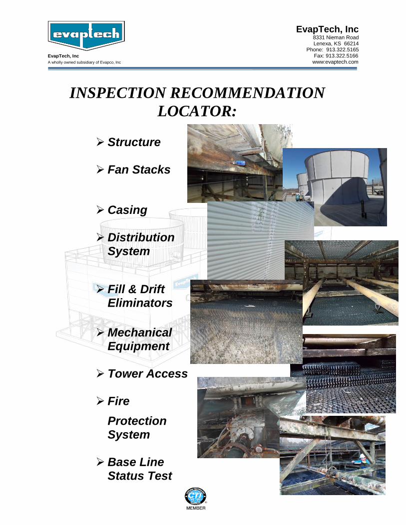
All ties and/or girt lines under the fan area in the plenum area of the tower are in poor and failing condition. The three (3) double 2 x 8 girt lines at C, D and E (in the longitudinal direction – SEE SKETCH BELOW) should be replaced from one end of the tower to the other. All the 2 x 6’s at the fan deck level, above the 2 x8’s in the transverse direction, under the fan area, should be replaced as well. Plenum structure area above the drifts, exposed to direct sunlight, is a major concern for wood deteriorating - areas should be replaced.
EvapTech, Inc
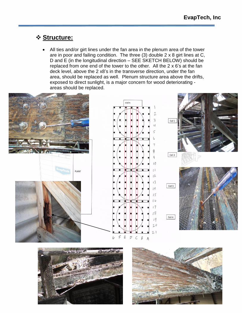
In addition to deteriorating members in the plenum area under the fans, there is sufficient evidence of iron rot from old sprinkler hanger hardware on many of the 2 x 8, 4 x 4, and 2 x 6.
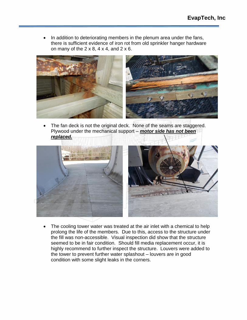
The fan deck is not the original deck. None of the seams are staggered. Plywood under the mechanical support – motor side has not been replaced.
The cooling tower water was treated at the air inlet with a chemical to help prolong the life of the members. Due to this, access to the structure under the fill was non-accessible. Visual inspection did show that the structure seemed to be in fair condition. Should fill media replacement occur, it is highly recommend to further inspect the structure. Louvers were added to the tower to prevent further water splashout – louvers are in good condition with some slight leaks in the corners.
EvapTech, Inc
Fan Stacks:
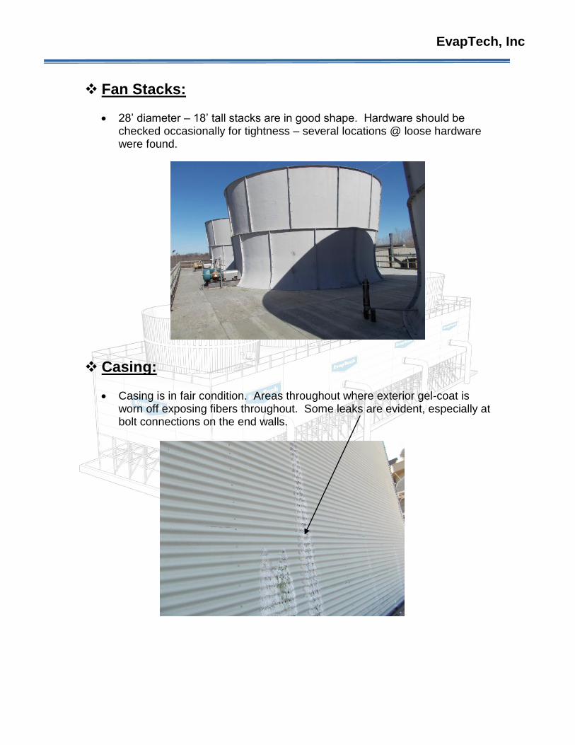
28’ diameter – 18’ tall stacks are in good shape. Hardware should be checked occasionally for tightness – several locations @ loose hardware were found.
Casing:
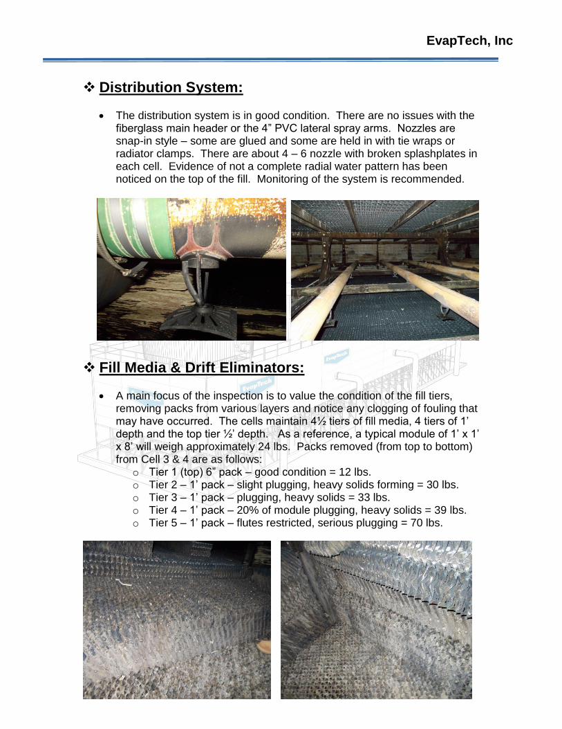
Casing is in fair condition. Areas throughout where exterior gel-coat is worn off exposing fibers throughout. Some leaks are evident, especially at bolt connections on the end walls.
EvapTech, Inc
Distribution System:
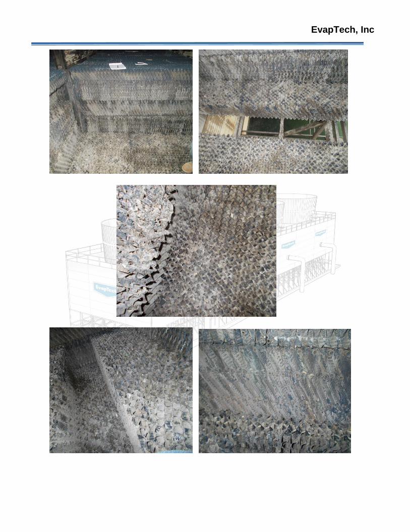
The distribution system is in good condition. There are no issues with the fiberglass main header or the 4” PVC lateral spray arms. Nozzles are snap-in style – some are glued and some are held in with tie wraps or radiator clamps. There are about 4 – 6 nozzle with broken splashplates in each cell. Evidence of not a complete radial water pattern has been noticed on the top of the fill. Monitoring of the system is recommended.
Fill Media & Drift Eliminators:
A main focus of the inspection is to value the condition of the fill tiers, removing packs from various layers and notice any clogging of fouling that may have occurred. The cells maintain 4½ tiers of fill media, 4 tiers of 1’ depth and the top tier ½’ depth. As a reference, a typical module of 1’ x 1’ x 8’ will weigh approximately 24 lbs. Packs removed (from top to bottom) from Cell 3 & 4 are as follows:
o Tier 1 (top) 6” pack – good condition = 12 lbs. o Tier 2 – 1’ pack – slight plugging, heavy solids forming = 30 lbs. o Tier 3 – 1’ pack – plugging, heavy solids = 33 lbs. o Tier 4 – 1’ pack – 20% of module plugging, heavy solids = 39 lbs. o Tier 5 – 1’ pack – flutes restricted, serious plugging = 70 lbs.
EvapTech, Inc
EvapTech, Inc
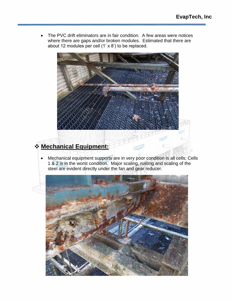
The PVC drift eliminators are in fair condition. A few areas were notices where there are gaps and/or broken modules. Estimated that there are about 12 modules per cell (1’ x 8’) to be replaced.
Mechanical Equipment:
Mechanical equipment supports are in very poor condition is all cells; Cells 1 & 2 is in the worst condition. Major scaling, rusting and scaling of the steel are evident directly under the fan and gear reducer.
EvapTech, Inc
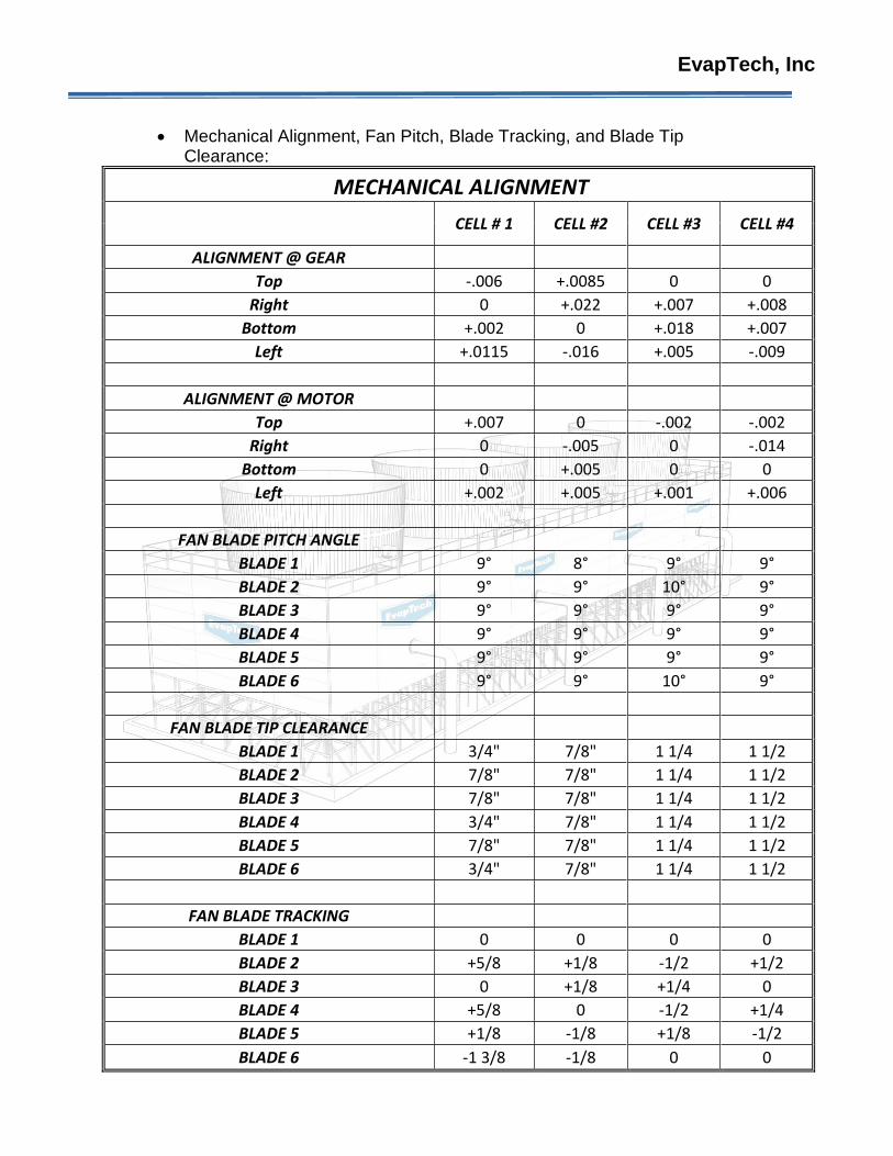
Mechanical Alignment, Fan Pitch, Blade Tracking, and Blade Tip Clearance:
MECHANICAL ALIGNMENT
CELL # 1 CELL #2 CELL #3 CELL #4
ALIGNMENT @ GEAR
Top -.006 +.0085 0 0
Right 0 +.022 +.007 +.008
Bottom +.002 0 +.018 +.007
Left +.0115 -.016 +.005 -.009
ALIGNMENT @ MOTOR
Top +.007 0 -.002 -.002
Right 0 -.005 0 -.014
Bottom 0 +.005 0 0
Left +.002 +.005 +.001 +.006
FAN BLADE PITCH ANGLE
BLADE 1 9° 8° 9° 9°
BLADE 2 9° 9° 10° 9°
BLADE 3 9° 9° 9° 9°
BLADE 4 9° 9° 9° 9°
BLADE 5 9° 9° 9° 9°
BLADE 6 9° 9° 10° 9°
FAN BLADE TIP CLEARANCE
BLADE 1 3/4" 7/8" 1 1/4 1 1/2
BLADE 2 7/8" 7/8" 1 1/4 1 1/2
BLADE 3 7/8" 7/8" 1 1/4 1 1/2
BLADE 4 3/4" 7/8" 1 1/4 1 1/2
BLADE 5 7/8" 7/8" 1 1/4 1 1/2
BLADE 6 3/4" 7/8" 1 1/4 1 1/2
FAN BLADE TRACKING
BLADE 1 0 0 0 0
BLADE 2 +5/8 +1/8 -1/2 +1/2
BLADE 3 0 +1/8 +1/4 0
BLADE 4 +5/8 0 -1/2 +1/4
BLADE 5 +1/8 -1/8 +1/8 -1/2
BLADE 6 -1 3/8 -1/8 0 0
EvapTech, Inc
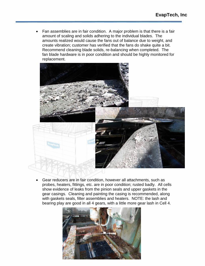
Fan assemblies are in fair condition. A major problem is that there is a fair amount of scaling and solids adhering to the individual blades. The amounts realized would cause the fans out of balance due to weight, and create vibration; customer has verified that the fans do shake quite a bit. Recommend cleaning blade solids, re-balancing when completed. The fan blade hardware is in poor condition and should be highly monitored for replacement.
Gear reducers are in fair condition, however all attachments, such as probes, heaters, fittings, etc. are in poor condition; rusted badly. All cells show evidence of leaks from the pinion seals and upper gaskets in the gear casings. Cleaning and painting the casing is recommended, along with gaskets seals, filter assemblies and heaters. NOTE: the lash and bearing play are good in all 4 gears, with a little more gear lash in Cell 4.
EvapTech, Inc
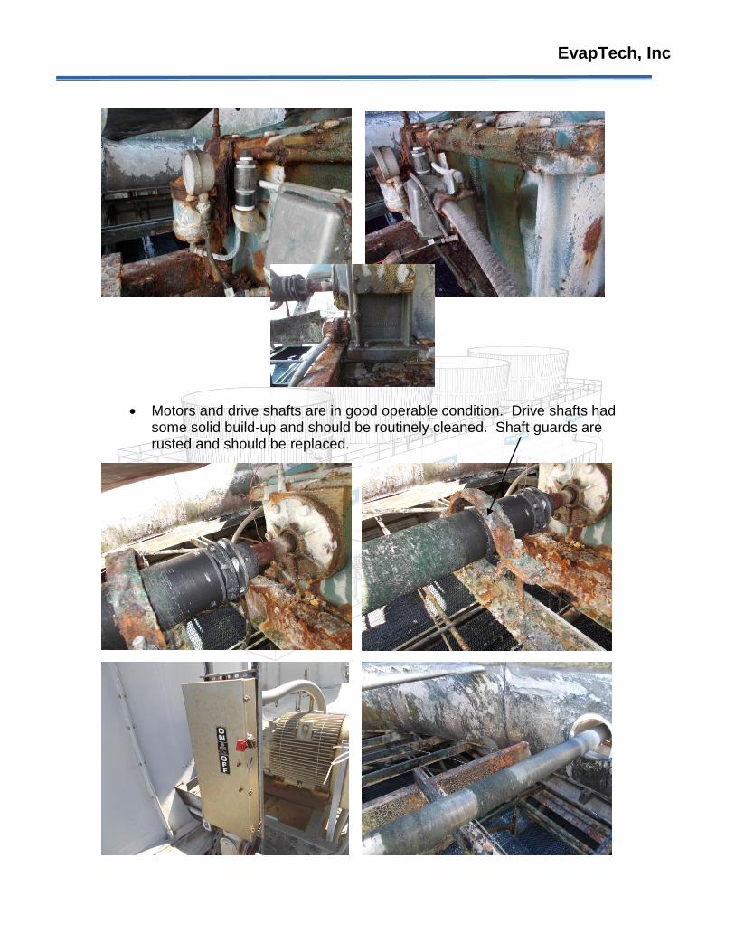
Motors and drive shafts are in good operable condition. Drive shafts had some solid build-up and should be routinely cleaned. Shaft guards are rusted and should be replaced.
EvapTech, Inc
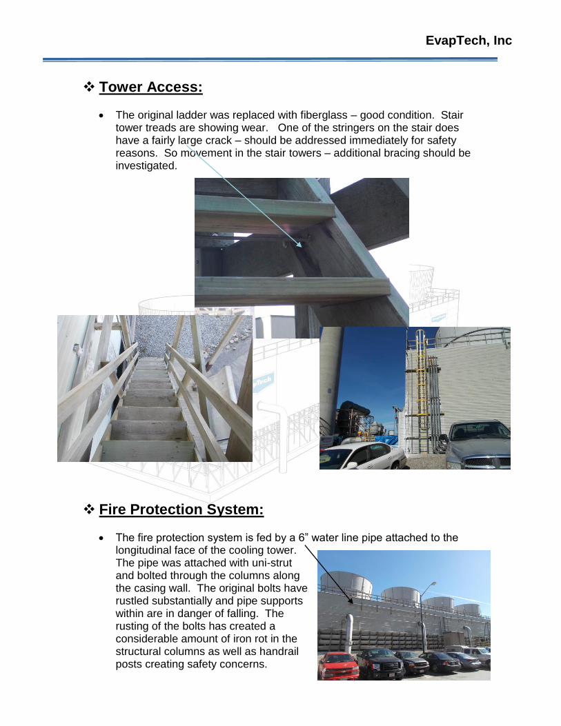
Tower Access:
The original ladder was replaced with fiberglass – good condition. Stair tower treads are showing wear. One of the stringers on the stair does have a fairly large crack – should be addressed immediately for safety reasons. So movement in the stair towers – additional bracing should be investigated.
Fire Protection System:
The fire protection system is fed by a 6” water line pipe attached to the longitudinal face of the cooling tower. The pipe was attached with uni-strut and bolted through the columns along the casing wall. The original bolts have rustled substantially and pipe supports within are in danger of falling. The rusting of the bolts has created a considerable amount of iron rot in the structural columns as well as handrail posts creating safety concerns.
EvapTech, Inc
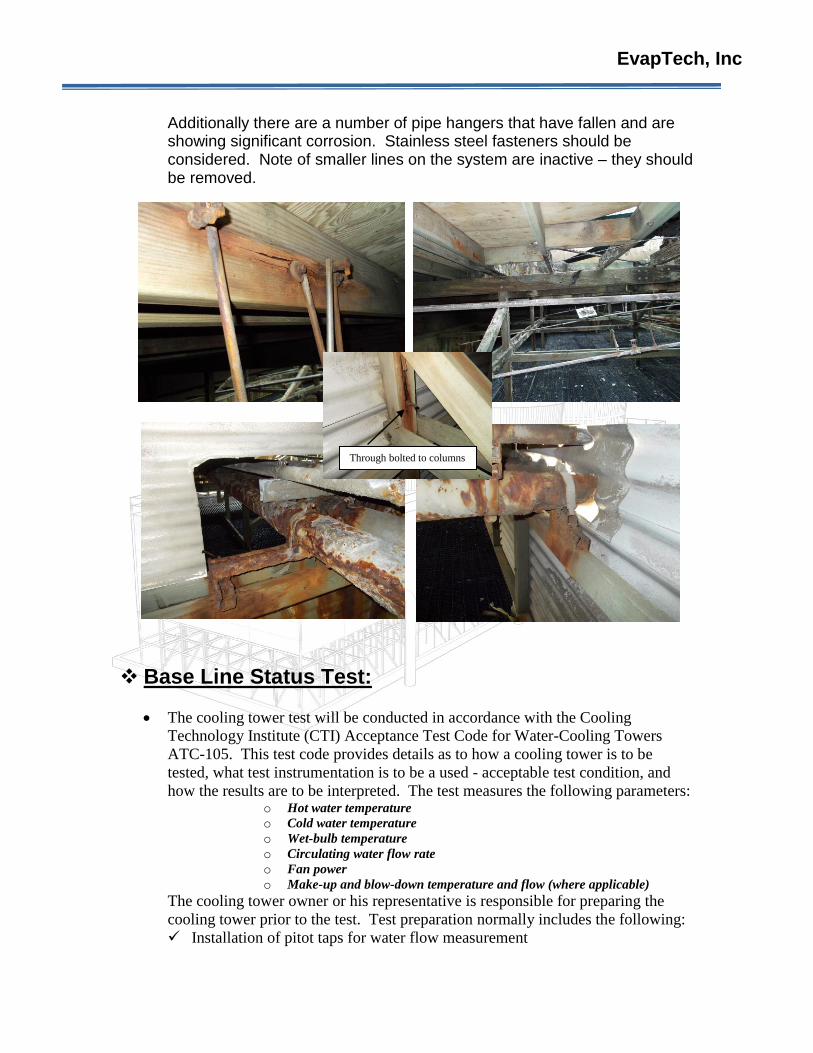
Additionally there are a number of pipe hangers that have fallen and are showing significant corrosion. Stainless steel fasteners should be considered. Note of smaller lines on the system are inactive – they should be removed.
Base Line Status Test:
The cooling tower test will be conducted in accordance with the Cooling
Technology Institute (CTI) Acceptance Test Code for Water-Cooling Towers
ATC-105. This test code provides details as to how a cooling tower is to be
tested, what test instrumentation is to be a used - acceptable test condition, and
how the results are to be interpreted. The test measures the following parameters: o Hot water temperature
o Cold water temperature
o Wet-bulb temperature
o Circulating water flow rate
o Fan power
o Make-up and blow-down temperature and flow (where applicable)
The cooling tower owner or his representative is responsible for preparing the
cooling tower prior to the test. Test preparation normally includes the following:
Installation of pitot taps for water flow measurement
Through bolted to columns
EvapTech, Inc
Provide information as to the diameter of the circulating water piping at the
water flow measurement location so that an appropriate sized pitot tube will
be available
Provision of a safe means of access to the pitot taps such as scaffolding or a
man lift
Provision of electric power (110 VAC) for operation of certain instruments
Installation of thermometer taps on the water inlet and outlet of the cooling
tower
Provision of an electrician or other qualified person for access to MCC to take
fan motor power readings
Provision of all work permits and safety clearance as required to conduct the
test
Provide performance curves and other tower design information as required
Provision of make-up and blow-down instrumentation or isolation where
required.
The tower owner must also insure that the test is conducted at a time when
plant operating conditions, tower condition, and weather are suitable for
testing.
For acceptance purposes, the test shall be conducted within the following
limitations and variations from design shall not be exceeded:
Wet-bulb temperature +/- 15° F
Range +/- 20%
Circulating water flow +/- 10%
Wind velocity average 10 miles per hr.
one-minute duration 15 miles per hr.
A final report including all raw data and capability calculations will be issued within
a reasonable time. Any deviations from the requirements of ATC-105 will be noted
in the report.
Recommendations:
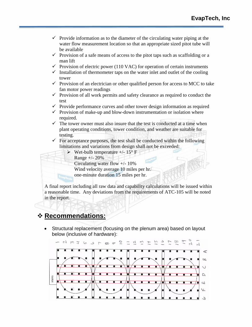
Structural replacement (focusing on the plenum area) based on layout below (inclusive of hardware):
EvapTech, Inc
o All Cells: 2 x 8’s in longitudinal bent lines C, D, and E 2 x 6’s in transverse bent lines
2,3,4,5,7,8,9,10,12,13,14,15,18,19, and 20 o Cell 1:
2 x 8 @ B 1/2, B 3/4, A 3/4, A 6/7, and F3/4 2 x 6 @ A/B 3, C/D/E 1, and CDE 1/2 2 x 4 @ CDE 2, CDE 3, CDE 4, CDE 5, C 1/2, D 1/2, E 1/2,
C 3/4, D 3/4, and E 3/4 Partition wall C/D 4 x 4 @ C4 and D5
o Cell 2: 2 x 8 @ B 8/9, G 9/10 2 x 6 @ A/B 10, A/B 8, F/G 8, and F/G 9 2 x 4 @ C 7/8, D 7/8, CDE 8, and CDE 9 4 x 4 @ A 10, G 10, and G9
o Cell 3: 2 x 6 @ fan stack 2 x 4 @ C 11/12/13, D11/12/13, and D 14/15 4 x 4 @ G11, G12, G13, G14, G15, and E15
o Cell 4: 2 x 8 @ G 18/19, F 18/19, B 18/19, F 16/17, and G16/17 2 x 6 @ A/B 20, A/B 19. A/B 18, and A/B 17 2 x 4 @ CDE 17, CDE18, CDE 19, CDE 20, C 17/18, D
17/18, and E 17/18
Replacement of mechanical equipment frames.
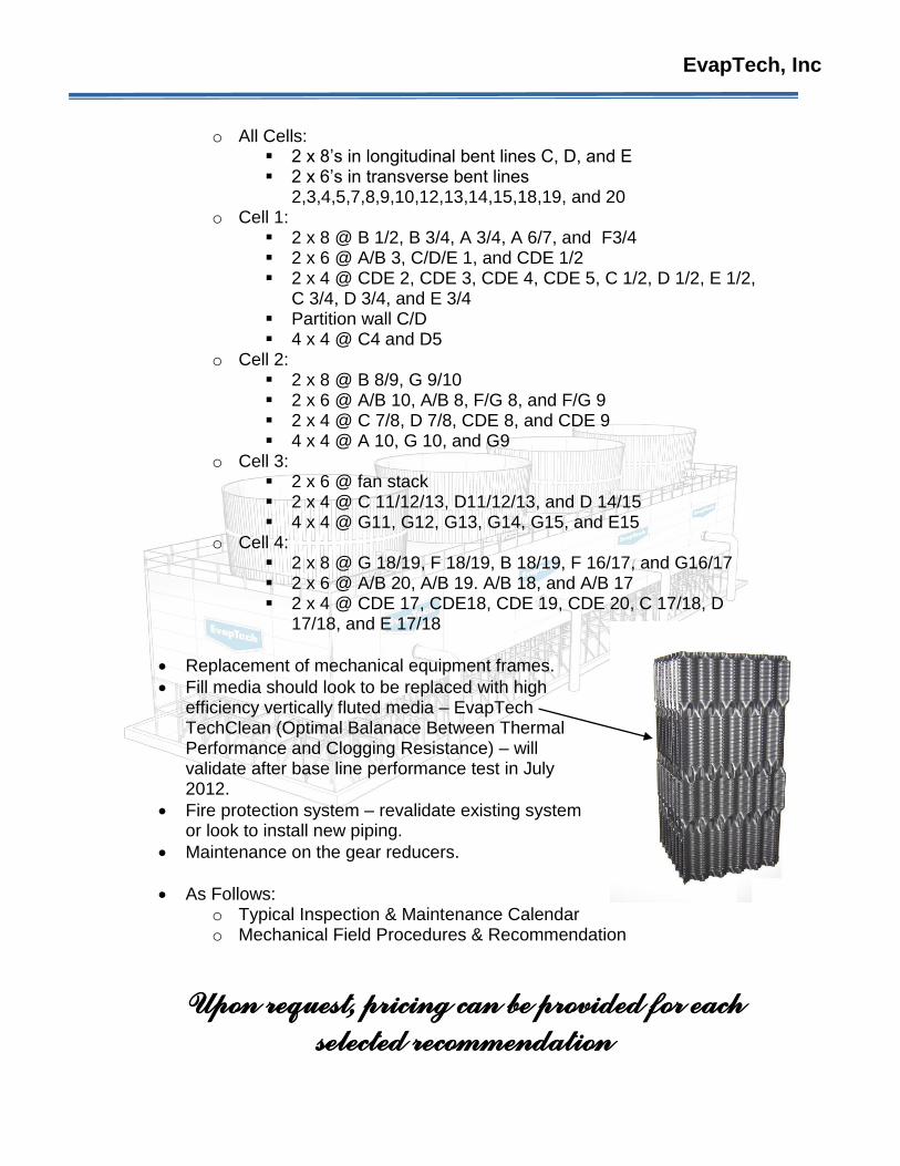
Fill media should look to be replaced with high efficiency vertically fluted media – EvapTech TechClean (Optimal Balanace Between Thermal Performance and Clogging Resistance) – will validate after base line performance test in July 2012.
Fire protection system – revalidate existing system or look to install new piping.
Maintenance on the gear reducers.
As Follows: o Typical Inspection & Maintenance Calendar o Mechanical Field Procedures & Recommendation
Upon request, pricing can be provided for each
selected recommendation
EvapTech, Inc
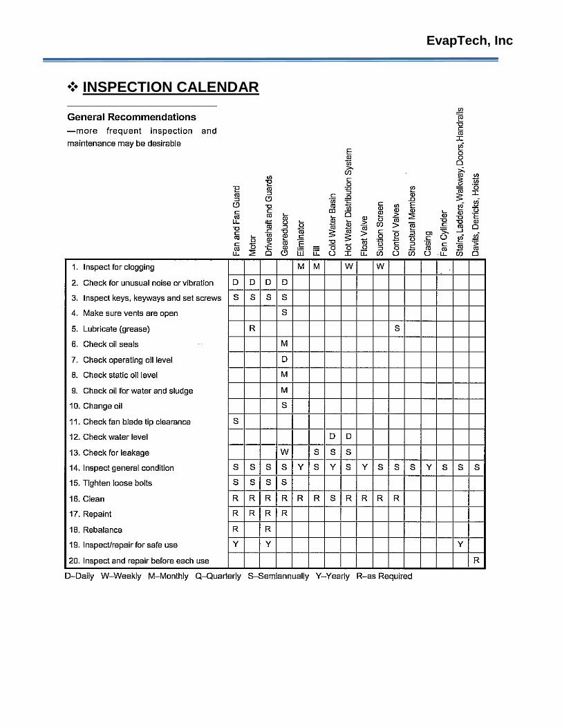
INSPECTION CALENDAR
EvapTech, Inc
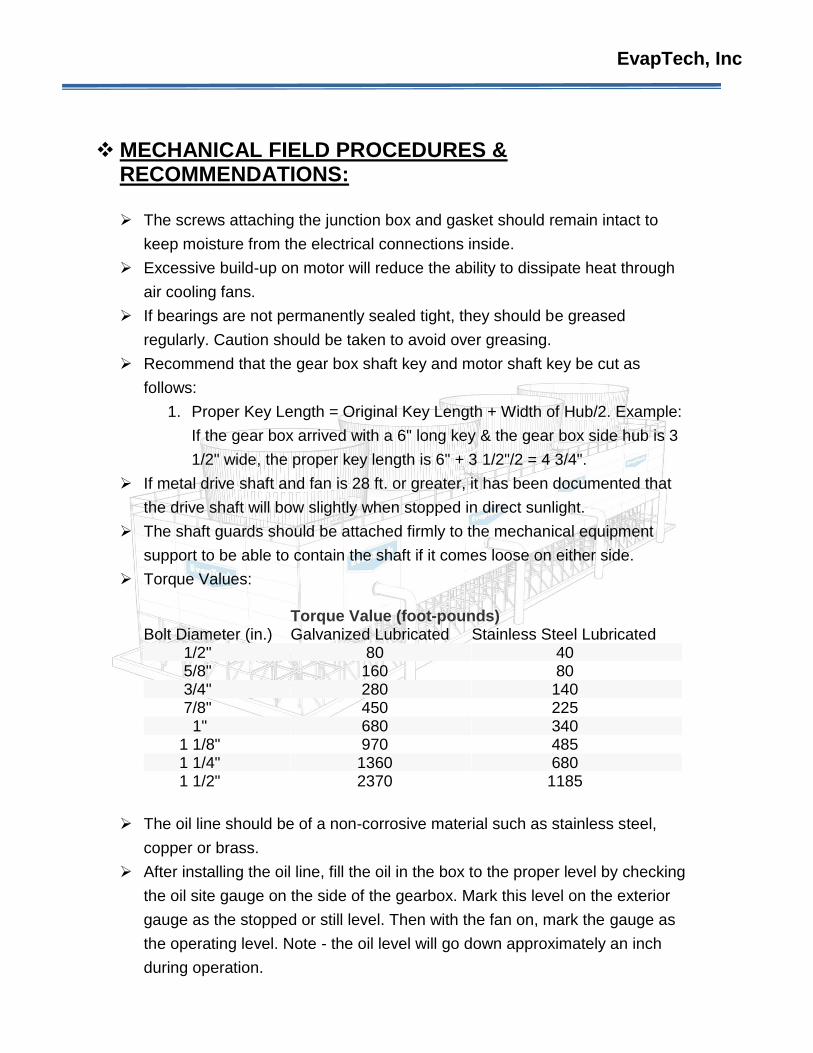
MECHANICAL FIELD PROCEDURES & RECOMMENDATIONS:
The screws attaching the junction box and gasket should remain intact to
keep moisture from the electrical connections inside.
Excessive build-up on motor will reduce the ability to dissipate heat through
air cooling fans.
If bearings are not permanently sealed tight, they should be greased
regularly. Caution should be taken to avoid over greasing.
Recommend that the gear box shaft key and motor shaft key be cut as
follows:
1. Proper Key Length = Original Key Length + Width of Hub/2. Example:
If the gear box arrived with a 6" long key & the gear box side hub is 3
1/2" wide, the proper key length is 6" + 3 1/2"/2 = 4 3/4".
If metal drive shaft and fan is 28 ft. or greater, it has been documented that
the drive shaft will bow slightly when stopped in direct sunlight.
The shaft guards should be attached firmly to the mechanical equipment
support to be able to contain the shaft if it comes loose on either side.
Torque Values:
Torque Value (foot-pounds)
Bolt Diameter (in.) Galvanized Lubricated Stainless Steel Lubricated 1/2" 80 40 5/8" 160 80 3/4" 280 140 7/8" 450 225 1" 680 340 1 1/8" 970 485 1 1/4" 1360 680 1 1/2" 2370 1185
The oil line should be of a non-corrosive material such as stainless steel,
copper or brass.
After installing the oil line, fill the oil in the box to the proper level by checking
the oil site gauge on the side of the gearbox. Mark this level on the exterior
gauge as the stopped or still level. Then with the fan on, mark the gauge as
the operating level. Note - the oil level will go down approximately an inch
during operation.
EvapTech, Inc
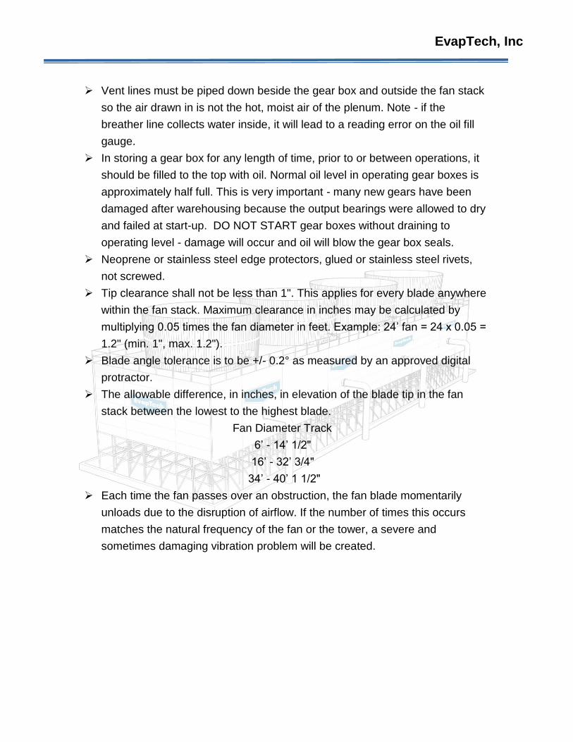
Vent lines must be piped down beside the gear box and outside the fan stack
so the air drawn in is not the hot, moist air of the plenum. Note - if the
breather line collects water inside, it will lead to a reading error on the oil fill
gauge.
In storing a gear box for any length of time, prior to or between operations, it
should be filled to the top with oil. Normal oil level in operating gear boxes is
approximately half full. This is very important - many new gears have been
damaged after warehousing because the output bearings were allowed to dry
and failed at start-up. DO NOT START gear boxes without draining to
operating level - damage will occur and oil will blow the gear box seals.
Neoprene or stainless steel edge protectors, glued or stainless steel rivets,
not screwed.
Tip clearance shall not be less than 1". This applies for every blade anywhere
within the fan stack. Maximum clearance in inches may be calculated by
multiplying 0.05 times the fan diameter in feet. Example: 24’ fan = 24 x 0.05 =
1.2" (min. 1", max. 1.2").
Blade angle tolerance is to be +/- 0.2° as measured by an approved digital
protractor.
The allowable difference, in inches, in elevation of the blade tip in the fan
stack between the lowest to the highest blade.
Fan Diameter Track
6’ - 14’ 1/2"
16’ - 32’ 3/4"
34’ - 40’ 1 1/2"
Each time the fan passes over an obstruction, the fan blade momentarily
unloads due to the disruption of airflow. If the number of times this occurs
matches the natural frequency of the fan or the tower, a severe and
sometimes damaging vibration problem will be created.