Implementing Precast, Prestressed Concrete Bridge Girder ...
Division of Construction Management
Inspection Manual For
Precast Prestressed Structural Members
April 2009

(This Page Intentionally Blank)

i
FOREWARD
This manual is intended to be used as a reference tool for Technicians working in Precast and or Prestressed Production Facilities where structural members are being cast for INDOT projects. This guide is intended to be a living document. As such, suggestions and comments are always welcome from the users of this manual. The Technician is advised to consult the Standard Specifications in conjunction with this manual as this training manual is intended to supplement the Standard Specifications and provide additional information for the Technician. This manual is not part of the Standard Specifications and thus the Fabricator is not bound or required to comply with any part of this manual. Thank you to the following persons for their time, help, and assistance to prepare this revised manual: Charles Bersch Lewis Clay Robert Dahman Mark Fligor David Hamilton William Jarvis Jim Reilman Perry White Tony Zander Special thanks are also extended to Prestress Services Industries, LLC, for granting us permission to use photos from their facilities in this manual. It is our intention that this manual be reviewed and updated on a five year cycle. Interim revisions may be issued at any time. 4-14-09 revised title page, page 23, and added page A-4

ii
(This Page Intentionally Blank)

iii
TABLE OF CONTENTS Chapter Page
1. DEFINITIONS AND TERMS................................................................................................ 1
2. INTRODUCTION .................................................................................................................. 3
3. NOTIFICATION & PREFABRICATION............................................................................. 7
4. MATERIALS.......................................................................................................................... 9
5. CASTING BED .................................................................................................................... 12
6 CONCRETE PLACEMENT ................................................................................................ 23
7. INSPECTION OF COMPLETED BEAMS ......................................................................... 29
8. HANDLING, STORAGE AND TRANSPORTATION....................................................... 31
9. ACCEPTANCE AND RELEASE FOR SHIPMENT .......................................................... 32
10. COLD WEATHER FABRICATION ................................................................................... 40
11. HOT WEATHER CONCRETE............................................................................................ 41
APPENDIX A
Allowable Dimensional Tolerances..................................................................................... A-1
Prefabrication Meeting Agenda........................................................................................... A-3

1
1. DEFINITIONS AND TERMS Wherever in this manual the following abbreviations are used, they are to be construed the same as the respective expressions represented. AASHTO – American Association of State Highway and Transportation Officials Approved Concrete Plant – A concrete plant meeting provisions of ITM 405 ASTM – American Society for Testing and Materials Camber – a slight convexity, arching, or curvature of a beam or girder for the purpose of
compensating for the deflection when loads are applied. CAPP – Certified Aggregate Producer Program Central Office – INDOT Office located at 100 N Senate Ave in the Indiana Government Center North Building in Indianapolis, Indiana. Contractor – The individual, partnership, firm, corporation, or combination of same contracting with or desiring to contract with the Department for performance of prescribed work. DTE – District Testing Engineer District Office – INDOT Office located within one of the six Districts Engineer – The Chief Engineer of the Department acting directly or through the duly authorized representative. Fabricator – Individual or firm who has subcontracted with the prime contractor to produce structural members for the contract. Frequency Manual – Frequency of Sampling and Testing Manual. Manual that outlines the sampling and testing requirements for materials used in the construction of INDOT projects. IAT – Independent Assurance Technician INDOT – Indiana Department of Transportation. The agency as constituted under the laws of Indiana for the administration of highway work. ITM – Indiana Test Method OMM – Office of Materials Management located at 120 Shortridge Road in Indianapolis, Indiana. PPE – Personal Protective Equipment. Items such as ear plugs, gloves, safety glasses, hard hat,
vest, etc… intended to provide protection to the user.

2
psi – pounds per square inch (lbs/sq. in.) QA – Quality Assurance A planned system of review and inspection procedures conducted by personnel not directly
involved in the fabrication process. Reviews verify that quality objectives were met, ensure that the fabrication represents the best possible efforts of those directly involved in the fabrication, and are a verification that the resulting members concur with the design drawings.
QC – Quality Control The self policing of a Fabricator to insure that the product meets the design drawings and specifications. QC provides routine and consistent checks to ensure correctness and completeness. A shop fabrication or quality control inspector usually heads up this effort. QCP – Quality Control Plan A written detailed plan per ITM 803 explaining how a Fabricator is going to control the quality of a structural member as it is being fabricated in order to produce the product in accordance with the specifications and design drawings. Structural Fabrication Supervisor – INDOT District Testing Employee that monitors all testing and quality issues during the production of Precast Prestressed structural members. This position may also serve as the Technician depending on INDOT staffing levels. Technician – The authorized representative of the Engineer charged with ensuring that QA goes into each contract. This person is responsible for observing and documenting the operations of the Fabricator. This individual may be either an INDOT employee or a consultant. Water / Cementitious Ratio – Total water divided by total cementitious material which can include fly ash or other pozzolans allowed by specification.
3
2. INTRODUCTION The primary purpose of this manual is to establish a uniform policy of inspection procedures and standards for the inspection of precast prestressed structural member fabrication. Also included in this manual is an example of the typical documentation required for the activities. The objective is to ensure that the fabricated precast prestressed structural member has been produced in accordance with INDOT plans and specifications. Technicians are assigned to Precast Prestressed Fabrication Shops for the purpose of QA inspection, and are the contacts between INDOT and the Fabricator. QA fabrication inspection requires constant and close attention to details and procedures required by INDOT to verify that the work performed by the Fabricator is of the quality required by the contract. The actual construction of a precast prestressed concrete structural member begins when the final approved shop drawings reach the shop fabrication floor and continues through fabrication until the structural members are finally put to use. The shop QC is responsible for the ultimate completion of a structural member in accordance with the design drawings and the approved shop drawings. The Technician is responsible for the QA portion of the work. Shop practices and procedures differ with each Fabricator and with each crew within each fabrication plant. INDOT’s intent is not to specify the procedures of each Fabricator, except to require that all procedures and workmanship are to be in accordance with the specifications and details on the plans. The most frequently used Standard Specification for this work is Section 707, Precast and Prestressed Concrete Structural Members. Lines of Authority & Communication The Technician has the authority, using the plans, Standard Specifications, and the contract special provisions to make decisions on acceptance or rejection of materials and members produced from these materials. Solutions to any discrepancies or disagreements with the Fabricator, which the Technician feels is beyond his authority to make, should immediately be referred to the District Testing Engineer (DTE). When necessary, the Central Office, Division of Construction Management is available to review and discuss situations that cannot be resolved between the Fabricator, the Technician, and the DTE. These situations should be reported to Central Office through the DTE. Safety Safety is of great importance to the Technician when working in the fabrication facility. At no time should the Technician be put in a potentially dangerous location or position in the fabrication facility. The Fabricator and Technician should work closely together to identify and correct any potentially dangerous situations. The Technician must follow all safety rules and regulations of the fabricating facility including wearing all required PPE. The employer will supply the Technician with the necessary PPE.
4
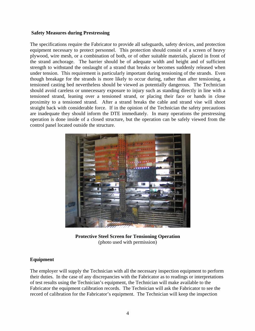
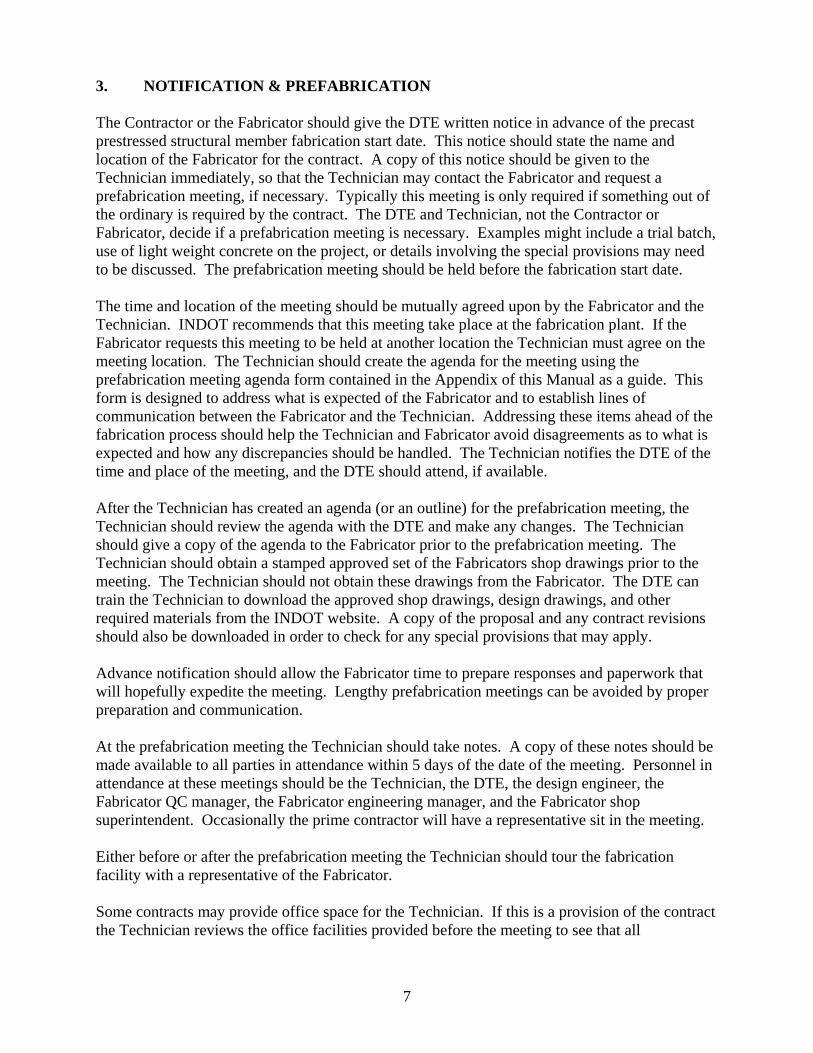
Safety Measures during Prestressing The specifications require the Fabricator to provide all safeguards, safety devices, and protection equipment necessary to protect personnel. This protection should consist of a screen of heavy plywood, wire mesh, or a combination of both, or of other suitable materials, placed in front of the strand anchorage. The barrier should be of adequate width and height and of sufficient strength to withstand the onslaught of a strand that breaks or becomes suddenly released when under tension. This requirement is particularly important during tensioning of the strands. Even though breakage for the strands is more likely to occur during, rather than after tensioning, a tensioned casting bed nevertheless should be viewed as potentially dangerous. The Technician should avoid careless or unnecessary exposure to injury such as standing directly in line with a tensioned strand, leaning over a tensioned strand, or placing their face or hands in close proximity to a tensioned strand. After a strand breaks the cable and strand vise will shoot straight back with considerable force. If in the opinion of the Technician the safety precautions are inadequate they should inform the DTE immediately. In many operations the prestressing operation is done inside of a closed structure, but the operation can be safely viewed from the control panel located outside the structure.
Protective Steel Screen for Tensioning Operation (photo used with permission)
Equipment The employer will supply the Technician with all the necessary inspection equipment to perform their duties. In the case of any discrepancies with the Fabricator as to readings or interpretations of test results using the Technician’s equipment, the Technician will make available to the Fabricator the equipment calibration records. The Technician will ask the Fabricator to see the record of calibration for the Fabricator’s equipment. The Technician will keep the inspection

5
equipment in calibration at all times. Most calibrations are done on a semi-annual or annual basis and are done either at the District Testing Lab or sent out for calibration. Plans & Specifications A thorough knowledge of the plans and specifications is essential before the Technician begins work on each contract. Prestressed materials are exposed to much higher stress values than found in ordinary work. The higher stress values necessitate field controls that include new design concepts. Without close attention to specified requirements, prestress work will not produce desired results. Every requirement listed has been placed on the plans or in the specifications for a definite purpose. The Technician is given a stamped “Approved” set of shop drawings from the DTE along with any special provisions for the contract. These drawings are stamped approved by Central Office Division of Structural Engineering or their designated representative. Fabrication should not begin until the Fabricator and Technician have an “Approved” set of shop drawings. A transmittal letter should accompany the shop drawings listing each approved drawing and any revisions.
The District Office provides the Technician with a set of Contract Information Books with all revisions and a set of design drawings for the contract. The Technician is encouraged to compare the design drawings to the shop drawings for any discrepancies. If the Technician does find any discrepancies between the design drawings and the Fabricator’s shop drawings the discrepancies should immediately be reported to the DTE. The Technician should remember that per 105.04, the design plans “out rank” approved shop drawings. In fact shop drawings are not listed in 105.04; in part because they are not something that is provided by INDOT. The design drawings, contract information books, and approved shop drawings are available electronically from the INDOT website and the Department’s Y: drive respectively. Technician Requirements The Technician must have a thorough knowledge of the following in order to perform the duties: INDOT Standard Specifications and Contract Special Provisions INDOT Frequency Manual Shop Drawings INDOT Design Drawings The Technician is required to be qualified in the following Test Methods: AASHTO T152.................................................................................................................... Air Test AASHTO T22................................................................................................ Compressive Strength AASHTO T23..................................................................................Making and Curing Specimens AASHTO T141.........................................................................................Sampling Fresh Concrete

6
AASHTO T119....................................................................................................................... Slump AASHTO T121...............................................................................Unit Weight and Relative Yield AASHTO T255....................................................................................Moisture Cookouts for Aggs ITM 207 ..........................................................................................................Sampling Aggregates ITM 403 .................................................................................................. Water-Cementitious Ratio *ASTM C173.................................................................................................... Volumetric Air Test (only if lightweight or slag aggregate is used)
7
3. NOTIFICATION & PREFABRICATION The Contractor or the Fabricator should give the DTE written notice in advance of the precast prestressed structural member fabrication start date. This notice should state the name and location of the Fabricator for the contract. A copy of this notice should be given to the Technician immediately, so that the Technician may contact the Fabricator and request a prefabrication meeting, if necessary. Typically this meeting is only required if something out of the ordinary is required by the contract. The DTE and Technician, not the Contractor or Fabricator, decide if a prefabrication meeting is necessary. Examples might include a trial batch, use of light weight concrete on the project, or details involving the special provisions may need to be discussed. The prefabrication meeting should be held before the fabrication start date. The time and location of the meeting should be mutually agreed upon by the Fabricator and the Technician. INDOT recommends that this meeting take place at the fabrication plant. If the Fabricator requests this meeting to be held at another location the Technician must agree on the meeting location. The Technician should create the agenda for the meeting using the prefabrication meeting agenda form contained in the Appendix of this Manual as a guide. This form is designed to address what is expected of the Fabricator and to establish lines of communication between the Fabricator and the Technician. Addressing these items ahead of the fabrication process should help the Technician and Fabricator avoid disagreements as to what is expected and how any discrepancies should be handled. The Technician notifies the DTE of the time and place of the meeting, and the DTE should attend, if available. After the Technician has created an agenda (or an outline) for the prefabrication meeting, the Technician should review the agenda with the DTE and make any changes. The Technician should give a copy of the agenda to the Fabricator prior to the prefabrication meeting. The Technician should obtain a stamped approved set of the Fabricators shop drawings prior to the meeting. The Technician should not obtain these drawings from the Fabricator. The DTE can train the Technician to download the approved shop drawings, design drawings, and other required materials from the INDOT website. A copy of the proposal and any contract revisions should also be downloaded in order to check for any special provisions that may apply. Advance notification should allow the Fabricator time to prepare responses and paperwork that will hopefully expedite the meeting. Lengthy prefabrication meetings can be avoided by proper preparation and communication. At the prefabrication meeting the Technician should take notes. A copy of these notes should be made available to all parties in attendance within 5 days of the date of the meeting. Personnel in attendance at these meetings should be the Technician, the DTE, the design engineer, the Fabricator QC manager, the Fabricator engineering manager, and the Fabricator shop superintendent. Occasionally the prime contractor will have a representative sit in the meeting. Either before or after the prefabrication meeting the Technician should tour the fabrication facility with a representative of the Fabricator. Some contracts may provide office space for the Technician. If this is a provision of the contract the Technician reviews the office facilities provided before the meeting to see that all

8
specification requirements are met. This is done prior to the meeting so that any issues with the facilities provided can be discussed and resolved at the meeting.
9
4. MATERIALS Reinforcing Bars Reinforcing bars must be supplied from a source listed on the Department’s Approved List of Certified Uncoated Reinforcing Bar Manufacturers and Certified Reinforcing Bar Epoxy Coaters, respectively. If the Fabricator plans to use ties to keep the reinforcing bars in position prior to and during the placement of concrete, the reinforcing must meet ASTM A615 or A706. If the Fabricator plans to weld the intersections of reinforcing bars to keep them in place, the reinforcing must meet ASTM A706. Reinforcing bars meeting ASTM A615 have higher carbon content and are not approved for welding, even tack welding. The Technician will obtain verification samples at the jobsite for testing as detailed in the Frequency Manual. Prestressing Strand Typically, prestressing strands consist of uncoated seven-wire stress-relieved strand meeting the requirements of ASTM A416 for the size and grade specified or as shown on the approved shop drawings. (See Subsection 910.01 (b) 7 of the Standard Specifications). The Technician must assure that a satisfactory Type A certification covering the strand is received from the manufacturer before the strand is used in the work. (For types of certifications, see Section 916 of the Standard Specifications). The certification should also show the actual modulus of elasticity of the strand and the area of the strand used to calculate the modulus of elasticity. The DTE can provide the most current ASTM A416 to the Technician so that the laboratory report can be compared to the current strand requirements. Concrete Per specification707.04(c), the total of all cementitious materials must not exceed 800 lb/cyd (475 kg/m3). The water-cementitious ratio of the concrete at the time of placement must be no more than 0.400. Cement and Pozzolans Cement or pozzolans must be in accordance with the specifications and after delivery to the fabrication facility must be stored in a clean, dry place and protected from moisture until used. Cement or pozzolans which have become partially set or contains lumps must not be used. Silica Fume is sometimes added in high strength applications. Aggregates Fine and coarse aggregates must meet the Standard Specifications. Aggregates used in precast concrete units are exempt from the Certified Aggregate Producer Program in accordance with Subsection 904.01. In accordance with ITM 203, sources supplying aggregates for prestressed
10
concrete items are required to have been ledge sampled. This is not a requirement for a precast only source. The coarse aggregate must be Class A or higher, Size No. 91 in accordance with subsection 904.03. Special lightweight coarse aggregates are sometimes incorporated into prestressed structural members. This concrete is then referred to as semi-lightweight concrete. These aggregates are typically used when the girder is very long. There is a special provision inserted into the contract document to detail the requirements for use of this aggregate. The aggregate the Fabricator proposes to use must have qualities run as per ITM 203. Fine aggregate must be natural sand, size No. 23. Manufactured sand is not allowed. If aggregates are supplied from a CAPP source and are of the specified quality, no further testing will be required. If the aggregates are not from a CAPP source and there is a concern with the aggregate, then a point-of-use sample may be obtained in accordance with the Office of Materials Management Directive No. 202.
Admixtures Portland Cement Concrete admixtures must be supplied from a source listed on the Department’s Approved List of PCC Admixtures and Admixture Systems. Admixtures Type A, D, F, or G may be used as provided in Section 707.04 (c). High range water reducing (HRWR) and high range water reducing retarding (HRWRR) admixture systems may be used as well. Admixtures Type B, C, or E may only be used when approved in writing. Concrete must be air entrained and meet requirements of 702.05. Mixing and Curing Water Water proposed for use in mixing or curing must be in accordance with 913.01. Concrete Plant If the Fabricator produces their own concrete, the Technician inspects the storage, mixing, and transportation of the materials. The materials must be stored, produced, and transported under applicable provisions of Section 702. The Technician performs the inspection as per Indiana Test Method 405 Portland Cement Concrete Plant Inspection.
Mix Designs All mix designs should be reviewed annually by the Technician and approved. If the Technician has a problem or question, the Technician should contact the DTE. These mixes can be adjusted
11
daily for fluctuations in aggregate moistures. A change in cement source, pozzolan source, admixture type or source, and /or aggregate source require the Fabricator to submit a new mix design. Some Fabricators use different mixes according to expected curing time. For example, a Fabricator might have a mix design with less cement than their “standard” mix to be used on Fridays when the members will cure all weekend in the forms. This practice is acceptable. The standard mixes that most Fabricators use can be approved without a trial batch. However, some special provisions require a mix design to be trial batched. For example, Semi-Lightweight Concrete requires a trial batch. The mix design must first be approved by the DTE. This approval must occur before the trial batch. All tests from the trial batch must meet the requirements of the special provisions and the specification limits of subsection 707.04 (c) before a mix design is approved for use. Strengths must be according to 707.04 (c) as well or the required 28 day strength from the shop drawings, whichever is greatest. The design Water/Cementitious Ratio (W/C) should be set below the maximum allowable level. The W/C ratio should be set at a level that corresponds with the level of Quality Control the Fabricator puts into monitoring the water/cementitious ratio. Elastomeric Bearings Elastomeric Bearings include plain bearings (consisting of elastomer material only) and laminated bearings (consisting of layers of elastomer material restrained at their interfaces by bonded laminates). The grade of the material must be as shown on the plans. The number, types, and sizes must be as specified or as shown on the plans or approved shop drawings. Not all bridges have bearing pads. First, check the plans to see if bearing pads are required. If bearing pads are required, talk to the Fabricator to see if the bearing pads were submitted for testing directly to the Office of Materials Management (OMM). If not, submit samples as per the Frequency Manual. Testing of the material takes a minimum of four weeks once received.
12
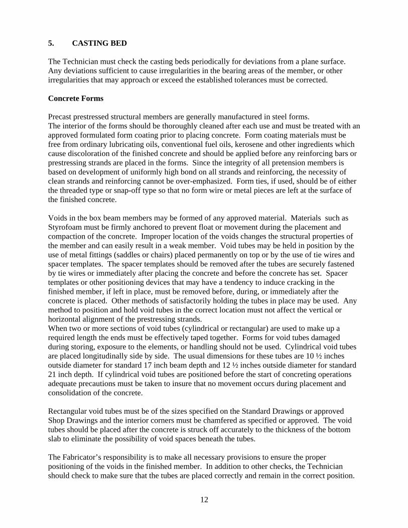
5. CASTING BED The Technician must check the casting beds periodically for deviations from a plane surface. Any deviations sufficient to cause irregularities in the bearing areas of the member, or other irregularities that may approach or exceed the established tolerances must be corrected. Concrete Forms Precast prestressed structural members are generally manufactured in steel forms. The interior of the forms should be thoroughly cleaned after each use and must be treated with an approved formulated form coating prior to placing concrete. Form coating materials must be free from ordinary lubricating oils, conventional fuel oils, kerosene and other ingredients which cause discoloration of the finished concrete and should be applied before any reinforcing bars or prestressing strands are placed in the forms. Since the integrity of all pretension members is based on development of uniformly high bond on all strands and reinforcing, the necessity of clean strands and reinforcing cannot be over-emphasized. Form ties, if used, should be of either the threaded type or snap-off type so that no form wire or metal pieces are left at the surface of the finished concrete.
Voids in the box beam members may be formed of any approved material. Materials such as Styrofoam must be firmly anchored to prevent float or movement during the placement and compaction of the concrete. Improper location of the voids changes the structural properties of the member and can easily result in a weak member. Void tubes may be held in position by the use of metal fittings (saddles or chairs) placed permanently on top or by the use of tie wires and spacer templates. The spacer templates should be removed after the tubes are securely fastened by tie wires or immediately after placing the concrete and before the concrete has set. Spacer templates or other positioning devices that may have a tendency to induce cracking in the finished member, if left in place, must be removed before, during, or immediately after the concrete is placed. Other methods of satisfactorily holding the tubes in place may be used. Any method to position and hold void tubes in the correct location must not affect the vertical or horizontal alignment of the prestressing strands. When two or more sections of void tubes (cylindrical or rectangular) are used to make up a required length the ends must be effectively taped together. Forms for void tubes damaged during storing, exposure to the elements, or handling should not be used. Cylindrical void tubes are placed longitudinally side by side. The usual dimensions for these tubes are 10 ½ inches outside diameter for standard 17 inch beam depth and 12 ½ inches outside diameter for standard 21 inch depth. If cylindrical void tubes are positioned before the start of concreting operations adequate precautions must be taken to insure that no movement occurs during placement and consolidation of the concrete.
Rectangular void tubes must be of the sizes specified on the Standard Drawings or approved Shop Drawings and the interior corners must be chamfered as specified or approved. The void tubes should be placed after the concrete is struck off accurately to the thickness of the bottom slab to eliminate the possibility of void spaces beneath the tubes.
The Fabricator’s responsibility is to make all necessary provisions to ensure the proper positioning of the voids in the finished member. In addition to other checks, the Technician should check to make sure that the tubes are placed correctly and remain in the correct position.
13
The Technician should check the location, position, and condition of the void drains. The voids are to be vented during the curing period.
Any and all voids are subject to a position check after the members have been constructed. Any member with a void out of position in excess of the specified tolerances may be rejected. Reinforcing Reinforcing bars, wire reinforcement, and prestressing strands should be stored under cover and protected at all times from damage. Reinforcement required to be bent should be accurately cold bent in a bending machine to the shapes shown on the plans. All bars in which cracks or splits occur must be rejected. All dimensions shown on the plans for spacing of reinforcing bars apply to centers of bars unless otherwise noted. All bars should be accurately placed and firmly anchored. The bars must retain their position as shown on the plans during concrete placement. Distances from the forms should be maintained by means of chairs, ties, hangers, or other approved supports. All reinforcement should be rigidly wired or securely fastened at sufficient intervals to hold the reinforcement in place. In lieu of tying, reinforcement (except prestressing strands) may be welded per 707.04. If any welding (including tack welding) is done, reinforcing bars meeting ASTM A 706 must be used. Layers of bars should be separated by approved spacers. Bars should be separated from horizontal surfaces by being suspended, or supported on approved metal chairs and spacers. Metal supports and spacers should be of such shape as to be easily encased in concrete and that portion which is in contact with the forms must be non-corrosive and non-staining material. The supports and spacers should be of a type approved by the Engineer. Vertical stirrups should always pass around main tension members and be securely attached. The use of pebbles, broken stone or bricks, metal pipe, wooden blocks or other similar devices for holding reinforcement or strands in position is not permitted. After being placed, all reinforcement is inspected and approved before the concrete is deposited. Care must be used not to disturb the positions of the bars, both during and after depositing the concrete. Splices All reinforcing bars should be furnished in the full lengths indicated on the shop plans unless splices are indicated. No other splicing is allowed, except with written permission of the Engineer. In case of lapped splices, bars should be placed in contact and rigidly clamped or wired in a manner approved by the Engineer. Insofar as possible, splices must be staggered and well distributed, or else located at points of low tensile stress. Splices are not permitted at points where the section does not provide a distance of at least two (2) inches between the splices and

14
the nearest adjacent bar or surface of the concrete unless indicated otherwise on the detail design drawings or approved shop drawings. Laps should be per 703.06. Prestressing Prestressing strands should be handled at all times in such a manner as to prevent “kinks” or “nicks”. The use of prestressing wires or strands having kinks, bends, nicks or other defects should not be permitted. Tensioned strands are subject to relaxation if subjected to excessive temperatures such as those produced by torches, welding equipment or sparks and should be protected accordingly. The strands must be of the type, size and number specified and must be located and spaced as shown on the detail design or approved shop drawings.

15
Locking devices hold strands securely in place (photo used with permission)
Elongation In all methods of tensioning, the stress induced in the prestressing strands must be measured both by gauges and by elongation of the tendons or strands. The following procedure should be followed when tensioning strands for prestressed concrete structural members: The elongation for the gauge length of the strand is computed accurately using the actual cross-sectional area and modulus of elasticity of the strand (from the laboratory report) and the design load per strand from the plans. The computed elongation and the design load are then adjusted to compensate for any operational losses or thermal corrections. (See IC 737, Section 9 on how elongation is computed.) The strands are tensioned to the adjusted design load. The actual elongation obtained on each strand is checked against the adjusted computed elongation and should fall within the allowable tolerance of 5 percent. The strands must be held securely in place and where necessary, galvanized chairs or other approved methods must be used to prevent sag of the strands and to assure the thickness of the concrete beneath the strands is as shown on the drawings. Draped strands, when specified, must be deflected at the third points or at the locations shown on the detail design drawings or approved shop drawings and must be securely held in place at all
16
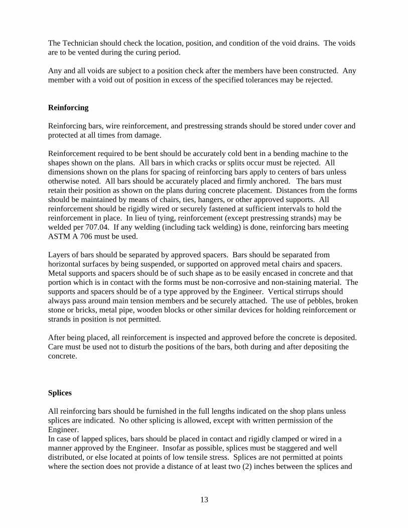
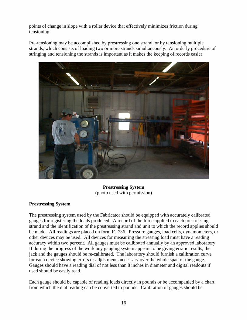
points of change in slope with a roller device that effectively minimizes friction during tensioning. Pre-tensioning may be accomplished by prestressing one strand, or by tensioning multiple strands, which consists of loading two or more strands simultaneously. An orderly procedure of stringing and tensioning the strands is important as it makes the keeping of records easier.
Prestressing System (photo used with permission)
Prestressing System The prestressing system used by the Fabricator should be equipped with accurately calibrated gauges for registering the loads produced. A record of the force applied to each prestressing strand and the identification of the prestressing strand and unit to which the record applies should be made. All readings are placed on form IC 736. Pressure gauges, load cells, dynamometers, or other devices may be used. All devices for measuring the stressing load must have a reading accuracy within two percent. All gauges must be calibrated annually by an approved laboratory. If during the progress of the work any gauging system appears to be giving erratic results, the jack and the gauges should be re-calibrated. The laboratory should furnish a calibration curve for each device showing errors or adjustments necessary over the whole span of the gauge. Gauges should have a reading dial of not less than 8 inches in diameter and digital readouts if used should be easily read. Each gauge should be capable of reading loads directly in pounds or be accompanied by a chart from which the dial reading can be converted to pounds. Calibration of gauges should be
17
accomplished with the gauges on the jacking system to be used in the prestressing operations. The load should be acting on the ram of the jack and in the same direction as the actual tensioning operation. The gauges must have a full pressure capacity of approximately twice the working pressure and unless calibration data clearly establishes accuracy over a greater range, the loads to be gauged must be not less than ¼ or more than ¾ the total graduated capacity of the dials. A tensioning system using hydraulic gauges must have appropriate by-pass piping valves and fittings so that the gauge point remains steady and does not fluctuate until the jacking load is released from the strand. Gauges should be mounted at near working eye level and within six feet of the operator. The operator and Technician need to be able to easily view the gauges to insure accurate and consistent readings. Initial Tensioning of Straight Strands Initial Tensioning After the prestressing strands have been positioned, a minimum initial tensioning force of 1000 pounds must be applied to each strand to be tensioned to equalize the stresses in the strands. This may be increased if necessary but should not normally exceed a value of 5000 pounds. The magnitude of the initial tensioning force should be the minimum force necessary to equalize the stresses and eliminate slack in the strands. The standard method used to apply the initial tensioning force is by use of a single strand tensioning jack. This is the same jack which is used for single strand tensioning but may be used for initial tensioning provided it is equipped with a proper gauging system that can register the initial tension force. The length of the casting bed and the number and size of the strands tensioned determines the magnitude of this force. Elongation measurements should not be used to determine the initial tensioning force. Properly calibrated load cells may be used to measure the initial tensioning force. The purpose of the initial tensioning is only to take up the slack in the strands so that elongation measurements may be made during final tensioning. The initial tensioning sequence for a group of strands must be such that the indicated tensile force is uniformly distributed in the strand throughout the length. In other words, the strand which is being tensioned must not be restrained by exterior forces. Where the strand passes through the stirrups, spirals, or headers, careful inspection is necessary to guard against binding which would result in substantial restraint. Avoiding entanglement of the strands during tensioning can be accomplished by having a definite sequence of laying and tensioning. In most cases the laying of the strands should progress from the bottom row of the strand group to the top row. The initial tensioning should be done in the reverse order. When single strand jacking is used, the jacking ram has a tendency to rotate due to the unwinding action of the strand. This rotation must be minimized as considerable losses can occur in the strand tension if unwinding in excess of one turn is permitted. Initial Tensioning of Draped Strands Draped pre-tensioned strands are tensioned entirely by jacking with the strands held in their draped position by means of rollers or other approved methods during the jacking operation. The low-friction free turning rollers must be used at all points of change in slope (hold-up and hold-down points) of strand trajectory at the time of tensioning. The tensioning of draped strands applied by jacking is done in essentially the same manner and must conform to the same
18
requirements as the tensioning for straight strands. Any other method used for tensioning draped strands must be indicated on the shop drawings and approved by the Designer of Record. The required procedure for tensioning draped strands in the deflected position by single strand jacking is as follows:
1. Apply initial tensioning load to strand. 2. Mark the strand for elongation measurement. 3. Apply the full tension load as determined by the jack gauge, not by elongation. 4. Measure elongation and determine the remaining elongation required for full tension
based on computed elongation. 5. Apply the full tension load to the other end of the strand and measure the elongation
at that end. The sum of the two elongation measurements from each end must be within the allowable tolerance of 5 percent.
6. The strand may be tensioned simultaneously at each end to the full tension load and the elongation measured at each end. The sum of the two elongation measurements must be within the allowable tolerance.
7. Single strand tensioning of the strands in the draped position by jacking the strands from only one end is permissible for shorter beds provided the strand elongation obtained is within the allowable tolerances and the required load on each strand is not exceeded.
8. Friction at each of the positioning devices resists some of the forces exerted in pulling the strands. The load actually applied to the strand, therefore, is decreased at each successive point of deflection away from the sources of pull. When several members are to be cast on the same bed, involving a large number of positioning devices and even though tensioning is performed from both ends, the loss of stress in the strand away from the source or sources of pull may be excessive as evidenced by undue disagreement between the load determined by the elongation measurement and that indicated by the gauges. When this situation occurs, the number of points of deflection must be reduced sufficiently so that the friction losses do not influence the tensioning beyond the 5% allowable tolerance.
9. The lengths of the strands to be used in calculating elongations should be the actual length of the strand along the trajectory between the fixed anchorage and the referenced point at the jacking end of the strand.
Up-lift and Hold-Down Devices Up-lift and hold-down devices should be attached in such a manner as to maintain the specified center to center spacing of strands in both the vertical and horizontal directions. Provisions should be made for the opening left by the removal of the restraining device to be grouted. Using aluminum sleeves or approved fiber sleeves for the hold-down bolts is satisfactory. Strand Splices The splicing of straight strands by approved means is usually permitted. Splices should meet AASHTO M – 203. Splice locations must not fall within the concrete member. Splices are preferred to be located on the “dead” end, (the end opposite the hydraulic jack). Spliced strands must have the same “twist” or “lap”. For single strand tensioning slippage of the splices should be considered in computing the elongation.
19
When tensioning multiple strands, either all of the strands or not more than 10 percent must be spliced, since correction for excessive slippage of individual strands cannot be made. If all of the strands are spliced the average splice slippage should be considered in computing the elongation. Splices can only be between the beams and not in the middle. If 10 percent or less of the strands are spliced no slippage allowance is required. Splicing is not permitted on draped strands. While prestressing operations are in progress the Technician should check the gauges indicating the tension load, and check the elongation to assure that the strand is not fowling or unwinding beyond the strand vise. The Technician should check for slippage in the strand vises and in the strand splices and for any movement of the anchorages or abutments. The Technician should also reference 707 for the number of permissible wire breaks. Any permissible wire breaks which may occur should be located and the ends securely tied to the strand with wire. A strand with a broken wire is tensioned to the same elongation as strands with no broken wires, but not to the same load. The elongation should be obtained with approximately 86 percent of the load required for whole strands. Measuring Elongation The degree of accuracy necessary in reading the elongation depends on the magnitude of elongation obtained, which in turn depends upon the length of strand tensioned. Measurements to the nearest 1/8 inch are satisfactory for casting beds of 150 feet or longer and to the nearest 1/16 inch for casting beds shorter than 150 feet. There may be possible differences between the adjusted computed elongation and the actual measured elongation. The allowable difference may be as much as 15 percent. In the event of a difference in excess of this amount, the entire operation should be carefully checked and the source of error determined and corrected before proceeding further. After the initial tensioning force has been applied to the strand, reference points for measuring the elongation due to additional forces must be established. The location of the reference points vary slightly with the different methods of tensioning strands and with the physical characteristics of the equipment used. The adjusted computed elongation and the plus and minus tolerance limits of 5 percent are accurately located from these reference points. The actual elongation obtained is then checked against the allowable tolerances. Calculations for elongation and jacking pressures must include appropriate allowances for thermal corrections, friction and all possible slippage and relaxation of the anchorages.
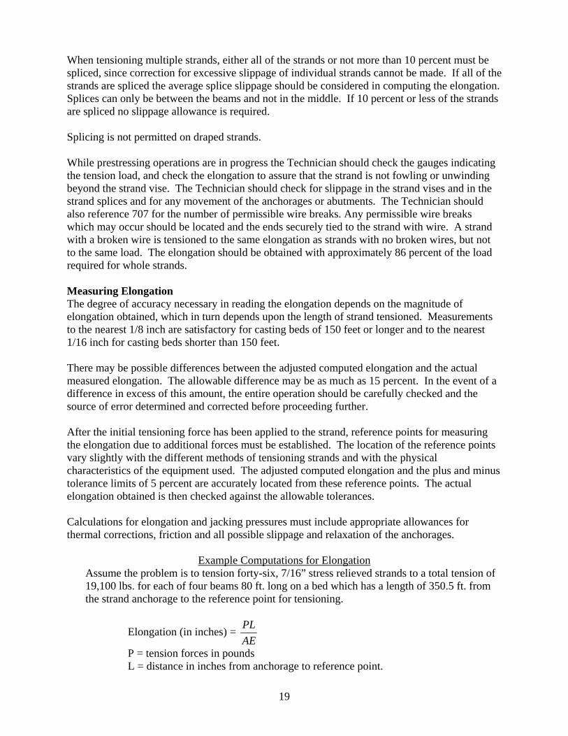
Example Computations for Elongation Assume the problem is to tension forty-six, 7/16” stress relieved strands to a total tension of 19,100 lbs. for each of four beams 80 ft. long on a bed which has a length of 350.5 ft. from the strand anchorage to the reference point for tensioning.
Elongation (in inches) = AEPL
P = tension forces in pounds L = distance in inches from anchorage to reference point.
20
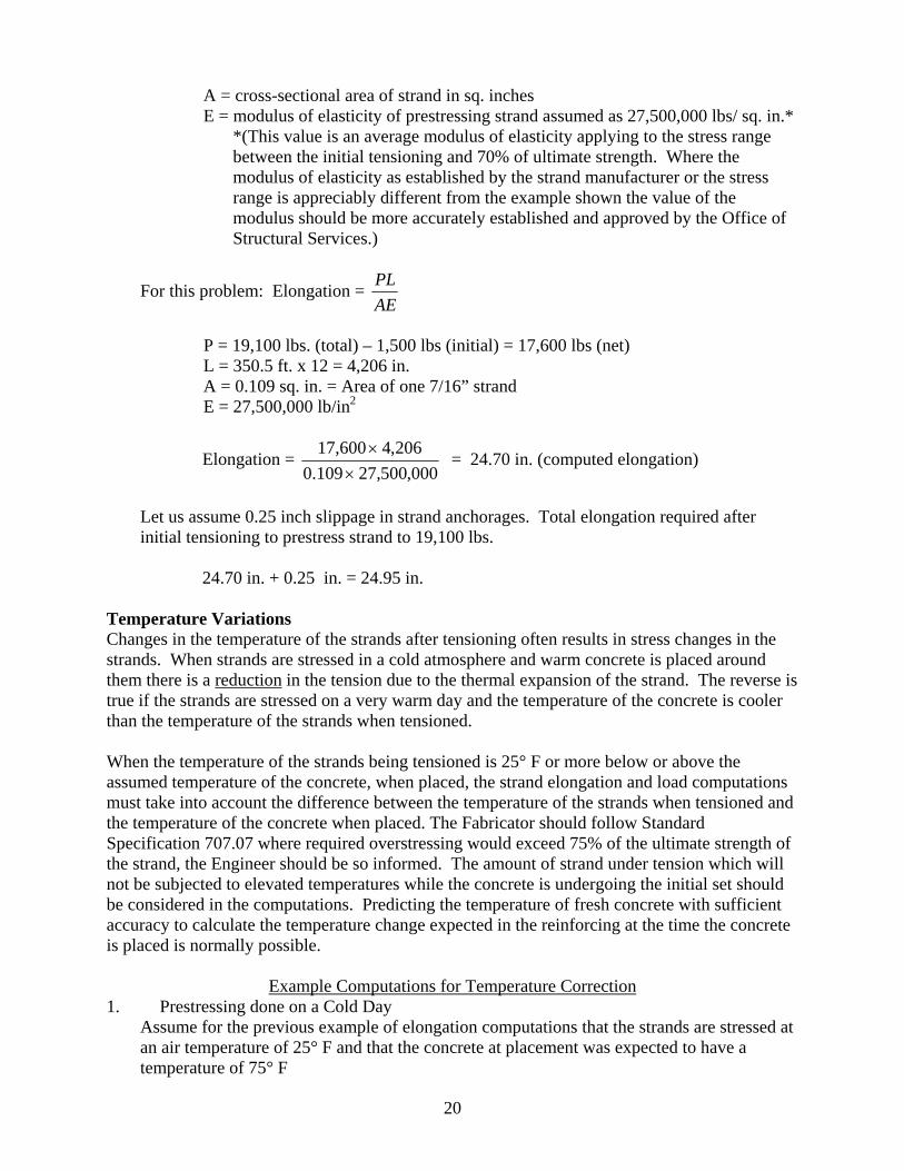
A = cross-sectional area of strand in sq. inches E = modulus of elasticity of prestressing strand assumed as 27,500,000 lbs/ sq. in.*
*(This value is an average modulus of elasticity applying to the stress range between the initial tensioning and 70% of ultimate strength. Where the modulus of elasticity as established by the strand manufacturer or the stress range is appreciably different from the example shown the value of the modulus should be more accurately established and approved by the Office of Structural Services.)
For this problem: Elongation = AEPL
P = 19,100 lbs. (total) – 1,500 lbs (initial) = 17,600 lbs (net) L = 350.5 ft. x 12 = 4,206 in. A = 0.109 sq. in. = Area of one 7/16” strand E = 27,500,000 lb/in2
Elongation = 000,500,27109.0
206,4600,17×
× = 24.70 in. (computed elongation)
Let us assume 0.25 inch slippage in strand anchorages. Total elongation required after initial tensioning to prestress strand to 19,100 lbs. 24.70 in. + 0.25 in. = 24.95 in.
Temperature Variations Changes in the temperature of the strands after tensioning often results in stress changes in the strands. When strands are stressed in a cold atmosphere and warm concrete is placed around them there is a reduction in the tension due to the thermal expansion of the strand. The reverse is true if the strands are stressed on a very warm day and the temperature of the concrete is cooler than the temperature of the strands when tensioned.
When the temperature of the strands being tensioned is 25° F or more below or above the assumed temperature of the concrete, when placed, the strand elongation and load computations must take into account the difference between the temperature of the strands when tensioned and the temperature of the concrete when placed. The Fabricator should follow Standard Specification 707.07 where required overstressing would exceed 75% of the ultimate strength of the strand, the Engineer should be so informed. The amount of strand under tension which will not be subjected to elevated temperatures while the concrete is undergoing the initial set should be considered in the computations. Predicting the temperature of fresh concrete with sufficient accuracy to calculate the temperature change expected in the reinforcing at the time the concrete is placed is normally possible.
Example Computations for Temperature Correction
1. Prestressing done on a Cold Day Assume for the previous example of elongation computations that the strands are stressed at an air temperature of 25° F and that the concrete at placement was expected to have a temperature of 75° F
21
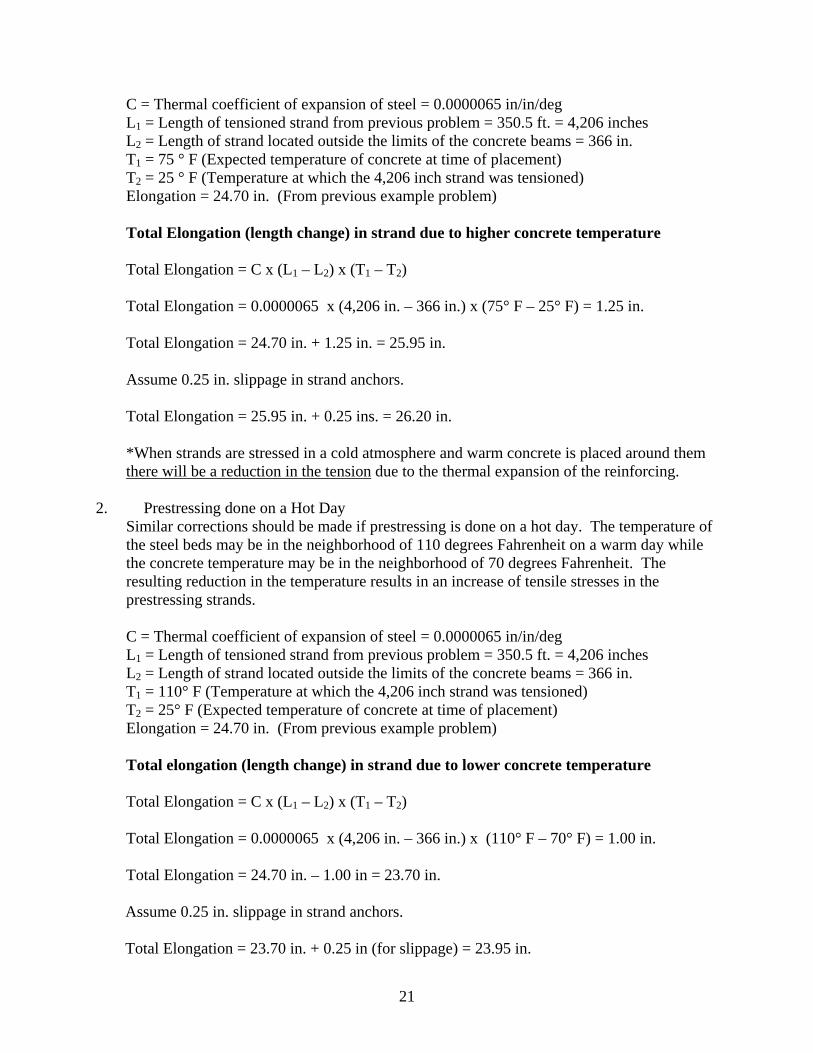
C = Thermal coefficient of expansion of steel = 0.0000065 in/in/deg L1 = Length of tensioned strand from previous problem = 350.5 ft. = 4,206 inches L2 = Length of strand located outside the limits of the concrete beams = 366 in. T1 = 75 ° F (Expected temperature of concrete at time of placement) T2 = 25 ° F (Temperature at which the 4,206 inch strand was tensioned) Elongation = 24.70 in. (From previous example problem) Total Elongation (length change) in strand due to higher concrete temperature Total Elongation = C x (L1 – L2) x (T1 – T2) Total Elongation = 0.0000065 x (4,206 in. – 366 in.) x (75° F – 25° F) = 1.25 in. Total Elongation = 24.70 in. + 1.25 in. = 25.95 in. Assume 0.25 in. slippage in strand anchors. Total Elongation = 25.95 in. + 0.25 ins. = 26.20 in. *When strands are stressed in a cold atmosphere and warm concrete is placed around them there will be a reduction in the tension due to the thermal expansion of the reinforcing.
2. Prestressing done on a Hot Day Similar corrections should be made if prestressing is done on a hot day. The temperature of the steel beds may be in the neighborhood of 110 degrees Fahrenheit on a warm day while the concrete temperature may be in the neighborhood of 70 degrees Fahrenheit. The resulting reduction in the temperature results in an increase of tensile stresses in the prestressing strands.
C = Thermal coefficient of expansion of steel = 0.0000065 in/in/deg L1 = Length of tensioned strand from previous problem = 350.5 ft. = 4,206 inches L2 = Length of strand located outside the limits of the concrete beams = 366 in. T1 = 110° F (Temperature at which the 4,206 inch strand was tensioned) T2 = 25° F (Expected temperature of concrete at time of placement) Elongation = 24.70 in. (From previous example problem) Total elongation (length change) in strand due to lower concrete temperature Total Elongation = C x (L1 – L2) x (T1 – T2) Total Elongation = 0.0000065 x (4,206 in. – 366 in.) x (110° F – 70° F) = 1.00 in. Total Elongation = 24.70 in. – 1.00 in = 23.70 in. Assume 0.25 in. slippage in strand anchors. Total Elongation = 23.70 in. + 0.25 in (for slippage) = 23.95 in.
22
*When strands are stressed in a warm atmosphere and cooler concrete is placed around them there will be an increase in the tension due to the thermal shrinkage of the reinforcing.
Slippage of Strand Anchors One of the most frequent causes of discrepancies between calculated and measured elongations is slippage of the gripping devices at either or both ends of the bed. In multiple strand tensioning, one or more grips may slip considerably and not be detected by elongation or load measurement.
One way of detecting slippage is to mark each strand with a crayon or soapstone at a uniform distance of ½ inch to 1 inch from where it emerges from the gripping device. Movement of the mark shows the slippage. The slippage of the strand in the gripping device at the jacking end of the strand is easily detected after anchoring by determining the loss in measured elongation.
In normal operation most grips in common use slip from 1/8 in. to ¼ in depending on the type and condition of the grips. This means that a correction of as much as ½ in. may be necessary in calculations of elongation. Slight errors in corrections for grip slip are much less significant on the long beds than on short beds. For example, if the anticipated correction is ¼ in and the slip is actually ½ in., an elongation of 50 % will be in error less than one percent. On the other hand, if the total elongation is to be 4 inches, the ¼ in. errors in anticipated grip slip results in a six percent error in total elongation.
Another difficulty which should be guarded against is slow, gradual slippage in gripping devices from the time the initial tensioning is done until the concrete around the prestressing elements has set. The Technician needs to know about and watch for this unusual condition. Movement of Anchorage Abutments For each pre-tensioning operation the yield, deflection, or movement of the anchorage abutments must be determined. The value of this measured movement should reasonably compare with the assumed value in the elongation calculations. The significance of the discrepancy between the assumed and measured abutment movement is dependent upon the distance between the anchoring abutments. Usually if the combined movements exceed 1/16 in. per 100 feet of strand length, the need for applying corrections to the measured elongation and applied loads is indicated. The DTE should be consulted as to the corrections that the Technician proposes.
Elongation of Abutment Anchoring Bolts If anchor bolts used in the abutment anchoring system experience tensile stresses during prestressing, the elongation of these bolts must be considered in the elongation calculations. After the full tensile load has been applied to these bolts, the actual elongation must be measured and compared with the theoretical elongation. The significance of differences in these values is also dependent upon the length of the prestressing bed. The DTE should be consulted as to the corrections that the Technician proposes.

23
6 CONCRETE PLACEMENT Concrete used to produce precast prestressed structural members must be batched in an approved plant in accordance with ITM 405. A Quality Control Plan (QCP) must be prepared by the vendor that meets requirements of ITM 803. This plan must be approved by the DTE before production begins. Testing All concrete testing is performed by a qualified Technician employed by the Fabricator. This is QC testing. All concrete testing for precast prestressed structural members will be monitored by a qualified Technician employed by INDOT. This is QA oversight. If, as directed by the DTE, the qualified Technician employed by INDOT cannot be present for the compression testing to verify the minimum strength for prestress release has been achieved, the fabricator may proceed with the compression testing provided they complete the Certification of Compliance for Release of Prestress Force contained in the Appendix and provide this to the qualified Technician employed by INDOT. When the above procedure is utilized, INDOT should occasionally obtain test cylinders in order to perform verification testing. The frequency of verification testing is determined by the DTE. So that extra cylinders can be made, the Technician should notify the fabricator at the time the beam is cast that INDOT needs extra cylinders made. A Technician can be either Certified or Qualified. Certification can be obtained from a trade organization such as American Concrete Institute (ACI), Precast/Prestressed Concrete Institute (PCI), or through INDOT. The Technician must attend a one week school and pass a written examination to be granted certification. Qualification is obtained through the Independent Assurance Program. A Qualified Technician must pass a written exam and demonstrate proficiency for each individual test that he will perform. The written test and demonstration of proficiency are given by one of the IATs located in each INDOT district. Required tests include air, slump, yield, water/cement ratio, making and compressive strength testing of cylinders, aggregate correction, and aggregate sampling. Fabricator Technicians possessing ACI, Grade I certification must demonstrate proficiency to the IAT every year in order to conduct field acceptance tests. All Certified and Qualified Technicians are entered into the site manager log of Technicians. Entrained Air Concrete must be air entrained. Air entraining and other types of concrete admixtures must be on an approved list as maintained by the Office of Materials Management. Air content will be determined as per AASHTO T152 or ASTM C173 for semi-lightweight concrete. Air content tests are made in accordance with the requirements of the Manual for Frequency of Sampling and Testing or as directed by the Structural Fabrication Supervisor. The results of all tests taken are shared between INDOT and the Fabricator. Tests for entrained air must be made on concrete containing the same materials and employing the same type mixer and mixing procedure which is used on the work. The air test is taken as close as possible to the work location. Slump The concrete must be workable and of the desired consistency. The slump test is conducted per 505.01. Acceptable slump ranges are provided in 707.04. Slump tests are made in accordance

24
with the requirements of the Manual for Frequency of Sampling and Testing or as directed by the Structural Fabrication Supervisor. Strength Precast members that are not prestressed must have a minimum compressive strength of 4500 psi in 28 days per 707.04. All tests are monitored by an INDOT representative and the results will be readily available. Prestressed members must be in accordance with 707 unless otherwise shown on the plans. Water / Cement Ratio The maximum water cement ratio must comply with 707 and ITM 403. The total of Portland cement and other cementitious material must not exceed 800 lbs/cyd. Mixing Concrete materials must be stored, produced, and transported under applicable provisions of Section 702.07 and 702.09 of the Standard Specifications. Normally, concrete for precast prestressed structural members is mixed on site in a stationary mixer, truck mounted mixer, or a combination of the two. Ready mix concrete from an approved plant is also acceptable as long as not more than one half (½) hour elapses from the time mixing water is added and the mix is deposited in the forms. The batch-mixer must be approved by the Engineer and must:
a. insure a uniform distribution of the ingredients b. not operated beyond its rated capacity c. be equipped with a mechanical means to prevent addition of ingredients once
mixing is started d. contents of drum must be entirely emptied before the next batch is started
Placing Concrete must be placed in a continuous operation per 707.06 and 702.20 in order to produce a monolithic structural member free of any cold joints, areas of segregation, honeycomb, or planes of separation between layers. Concrete must be placed in the forms in such a manner so that the concrete does not free fall more than five (5) feet and no segregation occurs. The concrete must be placed in uniform layers and must be thoroughly compacted, during and immediately after placing, with vibrators and spading tools. Concrete Compressive Test Specimens During placement of the concrete, the Technician performs QA monitoring on the making of concrete compressive test specimens. These specimens are made per 707.04(c)3. Refer to the Frequency Manual for the number of compressive test specimens required. If the pour is large
25
and several members are cast from the same pour, additional specimens should be made so that full representation of the concrete in all members is obtained. If the Fabricator desires, more than six test specimens can be made. Ideally, larger members should have a set of cylinders made for compressive strength testing. Compressive test specimens or cylinders must be made in accordance with AASHTO T23 (ASTM C 31). INDOT currently requires that the cylinders are to be 6 inches in diameter and 12 inches in height despite some references in AASHTO T 23 and other industry manuals to 4 inch x 8 inch cylinders. The test specimen must be cured at the same location and the same manner as the member. Curing Curing may be done by accelerated curing or by wet curing in accordance with 707.07 and AASHTO T23, Section 10.2). Accelerated curing is generally done by low pressure steam although radiant heat may be used. The casting bed for any unit cured with steam must be completely enclosed by a suitable type of housing, tightly constructed so as to minimize heat and moisture loss. Water curing methods such as covering the top of the freshly set concrete with wet burlap must be used from the time the concrete is placed until steam is first applied. Curing must be maintained until the concrete reaches the minimum required strength for detensioning. In discontinuing the steam application, the air temperature inside the enclosure must decrease at a rate not to exceed 40 degrees Fahrenheit per hour until a temperature has reached 20 degrees F above the temperature of the air to which the concrete is exposed. Recording thermometers must be provided by the Fabricator and used to check these temperature requirements. De-tensioning The inspection of the finished product starts with the de-tensioning operation. The strands have been stressed, the conventional reinforcement has been placed, the forms have been positioned, all hardware and accessories have been installed, and the concrete placed and cured. Forms which may restrict either horizontal or vertical movement of prestressed members should be stripped, or at least loosened, prior to de-tensioning. Unless otherwise specified on the detail plans or approved shop drawings the minimum compressive strength of the concrete at time of prestressing must be 4000 psi as determined from compressive test specimens made at time beam was cast. The prestressing of the concrete beam requires the cutting or releasing of the tensioned strands outside the ends of the beam and transfers the tension load in the strand from the anchoring abutments to the concrete beam itself. If the concrete has been steamed cured, this must be done while the concrete is still warm and moist. Concrete changes in dimension as a consequence of temperature change and shrinkage. The temperature of members should be held reasonably constant during the curing period, especially the latter half of the curing period. If the concrete is permitted to dry and cool for any length of time prior to prestressing, dimensional changes take place which may cause cracks or undesirable stresses in the concrete due to restraint caused by the prestressing strands. This is especially true if hold-downs are used to deflect strands. Therefore, de-tensioning should be done immediately following the curing period and when test cylinder strengths indicate that the
26
required compressive strength has been obtained. Prestressing forces must never be applied to a member until the required compressive strength of the concrete has been reached. In all de-tensioning operations the prestressing forces must be kept symmetrical about the vertical axis of the member and must be applied in such a manner as to prevent any sudden or shock loading. Multiple Strand Release The strands may be released simultaneously by hydraulic jacking. With this method the total force is taken from the header by the jack, than gradually released. Some sliding of the members on the bed may occur, the amount of sliding being proportional to the exposed lengths of stressed strands between members and between the last member and the fixed end. In order to minimize sliding, these lengths should be held to the practical minimum. Members to be stressed by this method must be free from all factors retarding their movement, other than sliding friction on the bed. Single Strand Release Single strands may be released by heating and gradually parting the strands. Heating is performed on each strand, simultaneously, at both ends of the prestressing bed and preferably at all spaces between ends of adjacent members. Where spaces between ends of adjacent individual members are short, simultaneous heating at all spaces between members may not be required but any allowance must be in accordance with an approved sequence. In order for release of the strands to occur gradually the ends should not be quickly cut, but should be heated until the metal gradually loses its strength. Heating should be done with a low-oxygen flame (fairly large) applied along the strands for a distance of 2 to 5 inches. Strands should be heated in such a manner that failure of the first wire in each strand occurs after the torch has been applied for approximately five seconds or preferably longer. Symmetry of release must be observed at each beam end. Strands must be cut one at a time on opposite sides of the center line so the sequence used keeps the stresses nearly symmetrical about the axis of the members. Draped Pre-tensioned Strands Unless the plans or specification indicate otherwise, draped pre-tensioned strands should be de-tensioned in the following manner:
(1) Release the tension in the draped strands at the ends of the members by heating each strand until failure. The draped strands should be heated to failure at each uplifted point in accordance with an approved sequence or as shown on the shop drawings.
(2) All hold-down devices for the draped strands should be released and the hold-down bolts within the members removed.
(3) If any straight pre-tensioned strands are located within the members, the strands should be de-tensioned after the draped strands have been de-tensioned. Straight strands may be de-tensioned by either the single-strand or multiple strand release method, both of which have been previously discussed.
(4) Procedures for transfer of prestressing forces to members with deflected pre-tensioned strands are followed. Disregarding the procedure for transferring the forces to the members may result in unacceptable members.
27
Removal of Forms Per 707.07, side forms may be removed when no distortion, slump, or misalignment of the concrete will result. Precast members that are not prestressed must remain on the bottom supporting forms until the concrete has reached a compressive strength of at least 2000 psi as evidenced by test cylinders. Inspection and Repair of Surfaces Immediately after removal of the forms, the concrete surfaces must be inspected for honeycomb, voids, or other defects. Members having honeycombs or voids in or near the bottom of a member bearing area, or surrounding or exposing strands of reinforcing bars or prestressing strands are generally rejected. Minor voids or honeycomb not affecting the strength of a member, may be repaired, when approved by the Engineer, after the defective concrete has been removed and the area examined by him or his representative. The method of repair must be presented in writing and approved by the Engineer. Repairs must be made in the presence of the Technician. All repairs must be rubbed even with adjoining surfaces. Any evidence of plastering over an area or repairing a defective area without approval of the Engineer is sufficient cause for rejection of the member. The depressions left in the bottom of pre-tensioned members with draped strands after removal of the hold-down bolts should be cleaned of oil or grease and the surface roughened or keyed. The bottom and sides of the depression should be completely coated with an approved bonding compound, and the depression filled with a preapproved patch. Unless these precautions are taken the grout will most likely fall out due to the flexure of the beam. Cracks The intent is that structural members should be free from cracks and other defects. However, cracks occur and past studies have revealed that some cracks are entirely superficial (small in number and extent, on the top surface and not extending down the sides or into the body of the member) and do not have a detrimental effect on the structural quality of the members. In such instances some leeway may be permitted. Good references are: ACI Committee 224 Report: Control of Cracking in Concrete Structures, PCI Manual for the Evaluation And Repair of Precast, Prestressed Concrete Bridge Products. Cracks constitute potential locations for the start of disintegration of the concrete and no members with cracks, however small, should be accepted unless the cracks are effectively sealed, against the entrance of water, with a suitable epoxy resin. Cracks on the top surface of members must be grooved to a depth of ¼ inch to hold the sealing material. Cracks on the sides of members, which are only hair-line width, may be painted with the sealing material. End cracks must be sealed before the ends are given the required coatings of asphalt paint. Each instance of crack occurrence must be considered individually. When there is a possibility that a member with cracks may be acceptable the extent and magnitude of the crack or cracks

28
must be determined before the decision can be made. The method used to determine the extent and magnitude of the cracks must not reduce the structural capacity of the member. Whenever the Technician has any doubt whatsoever about the acceptability of a member, the DTE should be contacted. Rubbing and Sealing of Surfaces The outside vertical faces of fascia girders and the exposed face and top of the curb section are finished as described in 702.21. The tops of all beams and the outside faces of the fascia beams are sealed with an approved concrete sealer in accordance with 707.06 and 709.

29
7. INSPECTION OF COMPLETED BEAMS Checking Dimensions After the side forms are stripped and the surfaces of the member have been examined for defective concrete, the Technician must check the dimensions including camber and plumbness against those on the approved shop drawings and/or INDOT standards to determine if the beams are within the allowable tolerances. A table summarizing allowable tolerances for prestressed members can be found in Appendix A. These tolerances need to be checked periodically against the most current tolerances found in INDOT standard drawings 707- BPBF-01 to BPBF-03. The Technician must also check the horizontal alignment (sweep) of each beam.
Beams with dimensions falling outside the specified tolerances must be rejected unless approved corrective measures to correct the deficiency are completed. The QCP should contain provisions for corrective measures for out of tolerance beams. A written corrective action plan will be presented to the Engineer for approval. Length measurements that are only slightly outside the tolerance limit, especially in the case of beams of considerable length, must be subject to review in as much as the temperature of the concrete at the time the measurements are made has some influence on the length. Influence of temperature on other measurements may be considered negligible. Grinding of beams to allow measurements to fall within the specified tolerance may be permitted only with the written approval of the Engineer. The Technician should remember that the limits of tolerance do not necessarily represent full acceptable construction but are the limits at which construction may become unacceptable. The Technician and Fabricator should be working at a level of quality that is well within the tolerance limits. The Technician must inform the Fabricator of dimensions that approach the tolerance limits so that the proper adjustments can be made in future fabrication of members. Checking Camber The camber of each member is checked after the strands are released. Since there is a possibility of a change in camber occurring while members are in storage, the Technician should recheck the camber of each member just prior to shipping. The camber can be conveniently checked with a surveyor’s level by determining the elevation of marked points on top of the member at the ends and mid-point before and after the strands are released. The camber may also be checked by marking a point on the floor or bed at mid section of the member and placing a reference mark the same distance above this point, on the side of deck beams or on the lower flange of I-beams, before and after release of the strands, and measuring the distance between the two marks. Either of the methods outlined above must be accomplished just prior to and after releasing the strands and while the member is still on the casting bed. Another method of checking the camber that may be accomplished at any time the members are accessible is by means of a piano wire or line. Place a straight edge transversely under the beam successively at the ends and mid-point. Measure the same distance at the three points vertically above the straight edge, and place a mark on the side or flange of the member. Stretch a piano wire or line tightly between the marks at the ends of the member and note the distance between the wire or line and mark at the mid-point of the member. Care should be exercised to assure that there is a minimum amount of sag in the wire or line which should be compensated for, as
30
any sag not compensated for shows as camber in the member. Tests may be conducted in advance, to determine the maximum length for which this method would be sufficiently accurate. The pull or tension necessary for various lengths of wire or line, to reduce the sag to a minimum, could be determined and the sag measured at mid-point with a surveyor’s level or other suitable means. When checking for camber the pull or tension for a certain length wire or line, as previously determined, would be used and the sag, as previously measured for this condition, deducted from the mid-point measurement. The remaining measurement would be the amount of camber in the beam. The variation of camber must not be more than that permitted in the plans or standard drawings 707-BPBF-01 thru -03. If the camber is outside the allowable tolerances, the Office of Structural Services should be immediately contacted. The camber measured is recorded on Form IT573 (Yellow Card). Checking Plumbness The plumbness or vertical alignment of the beams should also be checked after the strands are released. Since there is a possibility of a change in plumbness occurring while a member is in storage, the Technician should recheck the plumbness of each member just prior to shipping. The Technician should be mindful that many beams have top and bottom flanges of different widths. Checking plumb is generally done by placing a carpenter’s level against the end of the beam and observing the vertical centerline of the beam section in relation to true vertical.
31
8. HANDLING, STORAGE AND TRANSPORTATION Handling, storage, and transportation of concrete structural members is described in 707.08. Members damaged by improper handling, storing, or transporting, are replaced at the Contractor’s expense. Handling The method of handling must be shown on the shop drawing and approved prior to use. To avoid damage to the members during handling, storing and transporting, it is essential that they remain in an upright position at all time. The beams should be lifted by the inserts or other approved devices for that purpose and should be supported as indicated below when in storage and during transportation to the constructors site. Storage In storage, the structural members must be fully supported across their width on battens. Supports for cantilever beams must be as shown on the plans. Due to storage limitations, structural members may be stacked no more than three members high. If members are stacked, they each must be supported as described. Transportation During transportation, the members must be supported with truck bolsters or battens. The ends of beams must extend no more than the depth of the beam.

32
9. ACCEPTANCE AND RELEASE FOR SHIPMENT If all other requirements have been met and the precast prestressed member meets the minimum 28 day compressive strength requirements, the member may be accepted for shipment. If the Contractor wishes to ship a member prior to 28 days, sufficient test specimens must be made to assure adequate 28 day results in the event the specimens broken earlier fail to meet the 28 day strength requirements. If all other requirements have been met and a member fails to meet the minimum 28 day strength requirement, the member must be rejected. The strength will be determined by breaking test cylinders made at the time the member was cast and cured in the identical manner, as the member. The average of at least two cylinders broken consecutively must meet the minimum strength requirement. If more than two cylinders are broken, then the average of all cylinders broken that day must meet the required strength. The minimum strength requirement for prestressed members is 5000 psi or as shown on shop drawings. There is no required or specified interval between breaks just that two consecutive breaks must pass. Coring the structural member in order to obtain a test specimen is not acceptable. Breaking Test Specimens Because testing at elevated temperatures may have adverse effect on strength, cylinders removed directly from steam curing should be permitted to cool to ambient temperature prior to testing. This is not a specification or AASHTO requirement but is a good rule of thumb. The test cylinders will be broken in accordance with AASHTO T22 (see appendix). Acceptance Forms The Technicians completes the following five forms:
Form IT-573 (Yellow Card) Form IC 734 Form IC 737 Form IC 7367 Form IC 735
IT-573 (Yellow Card) For each member accepted for shipment, the Technician completes one copy of form IT-573 (Yellow Card), and sends to the Project Engineer at the time of shipment. The camber of each member as measured just prior to shipping must be recorded on Form IT-573. The number of each accepted member is reported on the Form IT-573 representing that number. The primary purpose of Form IT-573 is to assure the Project Engineer/Project Supervisor that the member has been inspected, tested, and accepted before shipment. For this reason, the original is shipped with the beams. A copy of each yellow card is made and placed in the contract file.

33
Sample IT-573 (Yellow Card)
If beams must be shipped before 28 days and before sealing operations can begin, note this on the yellow card.
The basis for use for the Project Engineer is not the lab number from the yellow card but C999995 for visual as indicated in the Frequency Manual. IC 734 After the members for each bed or pour have been inspected and the specified 28 day strength has been met (See note below), Report Form IC 734 must be completed. The report is distributed with these accompanying certifications and documents as detailed below:
1. Type A Certification for the seven wire strand. 2. Type B Certification for Elastomeric Bearings, Laboratory Report for Bearings
(which is the Basis-For-Use for this item) and Mill Certifications for Bearings. 3. Letter from Fabricator detailing the Concrete Sealer from the Approved List used
to seal beams. 4. Certifications for any other materials when required by specifications or special
provisions. 5. All correspondence received and submitted pertaining to the members. 6. All Reports detailing repairs done to any of the members.
Form IC-734 with or without certifications are distributed as follows:
1. One copy to Division of Construction Management, Indianapolis (with certifications and additional documentation).
2. One copy to the District Construction Engineer of the District in which the structure is located (without certifications and additional documentation).
3. One copy to the District Testing Engineer of the District in which the structure is located (without certifications and additional documentation).

34
4. One copy to the Project Engineer/Project Supervisor (with certifications and additional documentation).
5. One copy (with certifications and additional documentation) retained for Technician’s File.
Note: All Members constructed for a specific job or contract should be reported on Form IC 734 whether or not the beam is accepted. If any member is rejected the reason for rejection should be given under “Remarks”. A filled-in example of an IC 734 is shown on the following pages.

35
Sample IC 734 page 1 filled-in
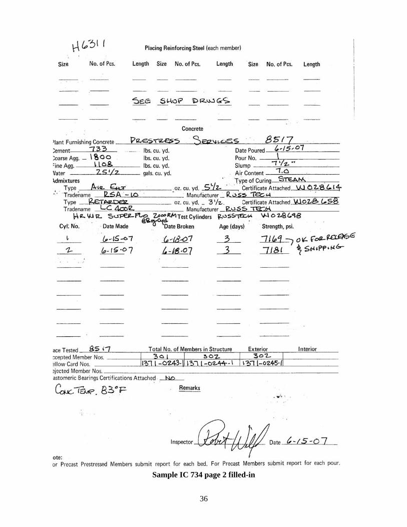
36
Sample IC 734 page 2 filled-in
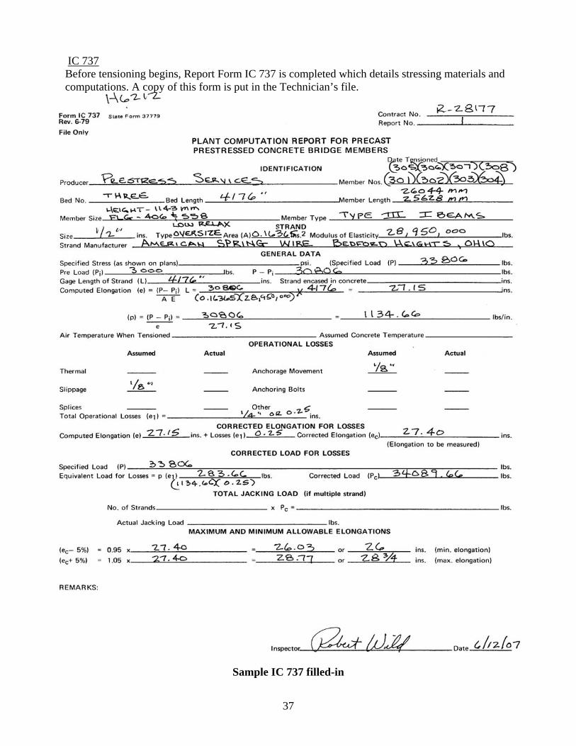
37
IC 737 Before tensioning begins, Report Form IC 737 is completed which details stressing materials and computations. A copy of this form is put in the Technician’s file.
Sample IC 737 filled-in
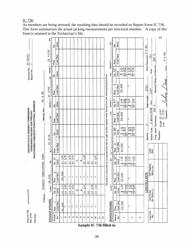
38
IC 736 As members are being stressed, the resulting data should be recorded on Report Form IC 736. This form summarizes the actual jacking measurements per structural member. A copy of this form is retained in the Technician’s file.
Sample IC 736 filled-in
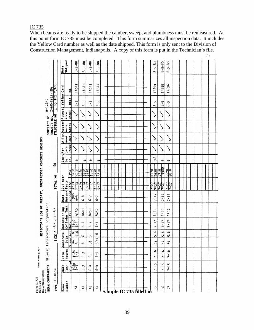
39
IC 735 When beams are ready to be shipped the camber, sweep, and plumbness must be remeasured. At this point form IC 735 must be completed. This form summarizes all inspection data. It includes the Yellow Card number as well as the date shipped. This form is only sent to the Division of Construction Management, Indianapolis. A copy of this form is put in the Technician’s file.
Sample IC 735 filled-in

40
10. COLD WEATHER FABRICATION In general, precast prestressed structural members poured in cold weather must meet the requirements for cold weather structural concrete detailed in Subsection 707.07. The use of calcium chloride to accelerate hardening of the concrete is not permitted under any circumstances.

41
11. HOT WEATHER CONCRETE In 702.11 under cold weather concrete it states “The maximum temperature of concrete produced with heated aggregates must be 90 degrees Fahrenheit”. INDOT specifications do not currently address hot weather concrete. The Technician may want to use this statement as a general guideline when placing concrete during unusually hot summer weather. The Fabricator may need to cast the structural members at night.

APPENDIX A
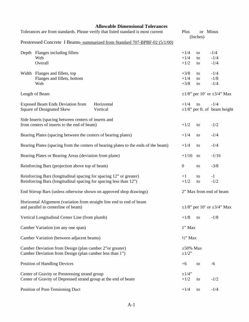
A-1
Allowable Dimensional Tolerances Tolerances are from standards. Please verify that listed standard is most current Plus or Minus
(Inches) Prestressed Concrete I Beams- summarized from Standard 707-BPBF-02 (5/1/00) Depth Flanges including fillets +1/4 to -1/4 Web +1/4 to -1/4 Overall +1/2 to -1/4 Width Flanges and fillets, top +3/8 to -1/4 Flanges and fillets, bottom +1/4 to -1/8 Web +3/8 to -1/4 Length of Beam ±1/8” per 10’ or ±3/4” Max Exposed Beam Ends Deviation from Horizontal +1/4 to -1/4 Square of Designated Skew Vertical ±1/8” per ft. of beam height Side Inserts (spacing between centers of inserts and from centers of inserts to the end of beam) +1/2 to -1/2 Bearing Plates (spacing between the centers of bearing plates) +1/4 to -1/4 Bearing Plates (spacing from the centers of bearing plates to the ends of the beam) +1/4 to -1/4 Bearing Plates or Bearing Areas (deviation from plane) +1/16 to -1/16 Reinforcing Bars (projection above top of beam) 0 to -3/8 Reinforcing Bars (longitudinal spacing for spacing 12” or greater) +1 to -1 Reinforcing Bars (longitudinal spacing for spacing less than 12”) +1/2 to -1/2 End Stirrup Bars (unless otherwise shown on approved shop drawings) 2” Max from end of beam Horizontal Alignment (variation from straight line end to end of beam and parallel to centerline of beam) ±1/8” per 10’ or ±3/4” Max Vertical Longitudinal Center Line (from plumb) +1/8 to -1/8 Camber Variation (on any one span) 1” Max Camber Variation (between adjacent beams) ½” Max Camber Deviation from Design (plan camber 2”or greater) ±50% Max Camber Deviation from Design (plan camber less than 1”) ±1/2” Position of Handling Devices +6 to -6 Center of Gravity or Prestressing strand group ±1/4” Center of Gravity of Depressed strand group at the end of beam +1/2 to -1/2 Position of Post-Tensioning Duct +1/4 to -1/4
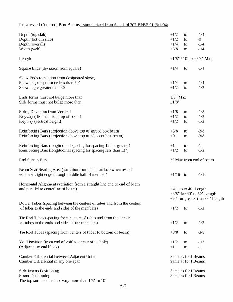
A-2
Prestressed Concrete Box Beams - summarized from Standard 707-BPBF-01 (9/1/04) Depth (top slab) +1/2 to -1/4 Depth (bottom slab) +1/2 to -0 Depth (overall) +1/4 to -1/4 Width (web) +3/8 to -1/4 Length ±1/8” / 10’ or ±3/4” Max Square Ends (deviation from square) +1/4 to -1/4 Skew Ends (deviation from designated skew) Skew angle equal to or less than 30o +1/4 to -1/4 Skew angle greater than 30o +1/2 to -1/2 Ends forms must not bulge more than 1/8” Max Side forms must not bulge more than ±1/8” Sides, Deviation from Vertical +1/8 to -1/8 Keyway (distance from top of beam) +1/2 to -1/2 Keyway (vertical height) +1/2 to -1/2 Reinforcing Bars (projection above top of spread box beam) +3/8 to -3/8 Reinforcing Bars (projection above top of adjacent box beam) +0 to -3/8 Reinforcing Bars (longitudinal spacing for spacing 12” or greater) +1 to -1 Reinforcing Bars (longitudinal spacing for spacing less than 12”) +1/2 to -1/2 End Stirrup Bars 2” Max from end of beam Beam Seat Bearing Area (variation from plane surface when tested with a straight edge through middle half of member) +1/16 to -1/16 Horizontal Alignment (variation from a straight line end to end of beam and parallel to centerline of beam) ±¼” up to 40’ Length ±3/8” for 40’ to 60’ Length
±½” for greater than 60’ Length Dowel Tubes (spacing between the centers of tubes and from the centers of tubes to the ends and sides of the members) +1/2 to -1/2 Tie Rod Tubes (spacing from centers of tubes and from the center of tubes to the ends and sides of the members) +1/2 to -1/2 Tie Rod Tubes (spacing from centers of tubes to bottom of beam) +3/8 to -3/8 Void Position (from end of void to center of tie hole) +1/2 to -1/2 (Adjacent to end block) +1 to -1 Camber Differential Between Adjacent Units Same as for I Beams Camber Differential in any one span Same as for I Beams Side Inserts Positioning Same as for I Beams Strand Positioning Same as for I Beams The top surface must not vary more than 1/8” in 10’

A-3
Prefabrication Meeting Agenda Date: Contract Number: Location of Meeting: Attendees: Fabricator’s Contact Name for this contract: Fabrication Schedule Needed: Yes No Fabricator to give advance notice to INDOT Technician: Yes No Does proposal list any special provisions Yes No Are Shop Drawing Complete and Approved Yes No If no then provide what revisions are to be made: Are Fabricator QC personnel qualified Yes No Is testing / production equipment meet calibration requirements Yes No Is plant INDOT approved Yes No Certifications are needed for all materials Yes No Tests Results are to be shared Yes No Notification of Special Materials ( i.e. light weight agg.) Yes No Plans for repair of deficient product Yes No Special Storage Requirements Yes No Any problems associated with past similar designs Yes No Planned Ship Dates Yes No Samples needed: 1. High Strength Bolts, Nuts, Washers of Every Size if Steel Diaphragms are used 2. Bearing Pads – Has sample been sent by supplier?

A-4
INDIANA DEPARTMENT OF TRANSPORTATION CERTIFICATION OF COMPLIANCE FOR RELEASE OF PRESTRESS FORCE
Name of Fabricator: _________________________________________________ Location of Fabricator:_______________________________________________ RE: Beam Mark(s) _______________________ on structure # ____________________________
fabricated for INDOT Contract #: ________________
The purpose of this certification is to provide documentation to the Indiana Department of Transportation (INDOT) of the date and time of the compression test cylinder results and the date and time that the prestress force was transferred from the jacks into the fabricated beam(s) identified by the beam mark(s) shown above since INDOT was unable to witness this process. a.m. Date of cylinder test: ______________________ Time of first cylinder break: ____________ p.m. Results of cylinder test(s): _______________________ psi (MPa)
_______________________ psi (MPa)
_______________________ psi (MPa)
_______________________ psi (MPa)
_______________________ psi (MPa)
Date prestress force transferred into the fabricated beam:___________________________________ a.m. Time prestress force transferred into the fabricated beam: _______________________________ p.m. Under penalties of perjury, I hereby certify that the information provided in this certification is a true and accurate recording of the above information observed during the compression cylinder testing process. I also affirm that I am the responsible party for quality control at the above-named fabricator. ___________________________________ ______________________________________
(Printed Name) (Signature) ___________________________________ ______________________________________
(Title) (Date)