Azul Zulu on Azure Overview -- OpenTech CEE Workshop, Warsaw, Poland
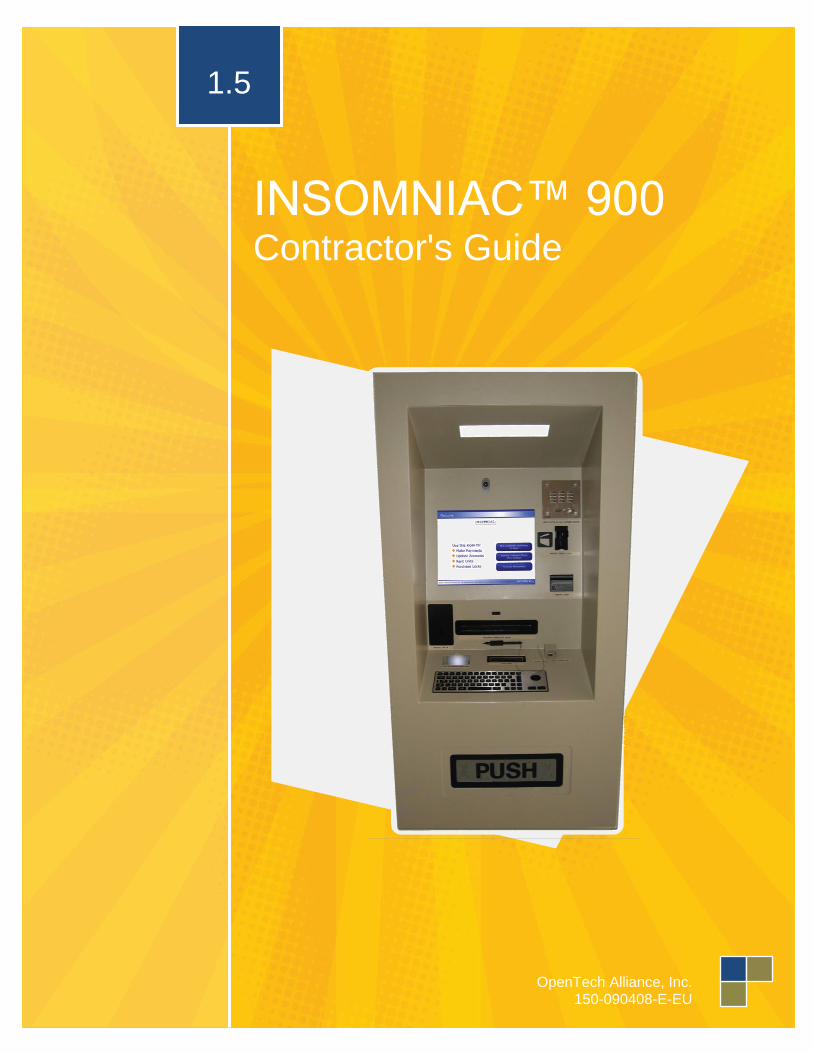
INSOMNIAC™ 900 Contractor's Guide
1.5
OpenTech Alliance, Inc.
150-090408-E-EU


Contact Us
2501 West Dunlap Avenue
Suite 255
Phoenix, Arizona 85021
Phone, Fax & Email
Technical Support (602) 773-1700
Fax (602) 324-8658
Office (602) 749-9370
Hours of Operation
Business Office Monday thru Friday – 8:00am to 5:00pm MST
Technical Support Monday thru Friday – 7:00am to 5:00pm MST
Saturday – 7:00am to 2:00pm MST
INSOMNIAC™ is a registered trademark of OpenTech Alliance, Inc. “Windows” and “Internet Explorer” are registered trademarks of the Microsoft Corporation. SiteLink, SiteLink-Web, STORE, TaskMaster, Storage Manager, Domico 2000, Storage Commander, Winsen, U-Haul, StorMan, Symbio and Total Recall are registered trademarks of their respected companies, granted use with permission. All configuration and/or installation references are appropriate practices within the U.S. Configuration
and installation procedures vary by country and may result in the presence of components that differ in
form and/or function from those shown in this document. Unless otherwise noted, all images,
illustrations, content and all materials shown in this document are copyrights, trademarks and or
intellectual properties, owned, controlled or licensed by OpenTech Alliance, Inc. This document may not
be copied in whole or in part without the written consent of OpenTech Alliance, Inc. Copyright © 2012,
OpenTech Alliance, Inc. all rights reserved.
DCN: 150-090408-E-EU

This page intentionally left blank

Table of Contents
Preface .......................................................... 7 Through-the-Wall Installation ......................... 7 Protection from Weather ................................ 7 ADA Compliance ........................................... 8
Accessibility Considerations............................... 8 Installation Specifications ................................... 8
Power Requirements ..................................... 8 Wired Power Specifications ............................... 8 Backup Power Supply ........................................ 8
Data Cable Requirements ............................. 9 Plenum Ceiling Consideration ....................... 9 Fire Protection Consideration ........................ 9
Heat Gain/Loss Consideration ....................... 9 INSOMNIAC 900 Specifications .................. 11
Weights and Measurements ............................. 11 Installation Specifications ................................. 11
Product & Installation Drawings ................... 12 Overall Views ................................................... 12 Rough Opening ................................................ 13 Side View ......................................................... 14 Enclosed in a Vestibule .................................... 15
Example of Installation Configurations ........ 16 Table of Figures........................................... 17

This page intentionally left blank

7 Preface
Contractor's Guide
151-090513-E-EU
Installation
Preface Prior to installing the INSOMNIAC 900, your contractor should review the standards and information
contained throughout this document. Please contact OpenTech Alliance Customer Support (via telephone
at: 602-749-9370, Option 2, or email at: [email protected]) for any upgrades or additional
details or questions.
Through-the-Wall Installation Check with OpenTech Alliance prior to
installation for any updates to this installation
guide.
Check differences between interior and exterior
floor elevations before cutting opening.
Check all applicable ADA and local codes for
accessibility compliance prior to installation.
The recommended height for the Lock
Dispenser is 20” above the finished floor.
The kiosk should be visible once a tenant
enters the property from the street.
The kiosk area should be well lit (to make the
user feel safe and comfortable).
The kiosk should be located on the exterior of
the building and visible from the parking area.
If the property utilizes video recording or
surveillance, a camera should be in place to
view the kiosk.
The kiosk should offer the user protection from
the elements during use; for example, shade
from the hot sun and direct sunlight, and
protection from rain and wind, etc.).
Ideal installation of the kiosk will ensure that it
is placed just adjacent to the main office entry.
The back of the kiosk should be accessible
from inside the main office (maintenance is
performed from the rear of the kiosk, as well as
reloading of merchandise, paper, etc.).
The kiosk should be located as close to the
entry keypad as possible.
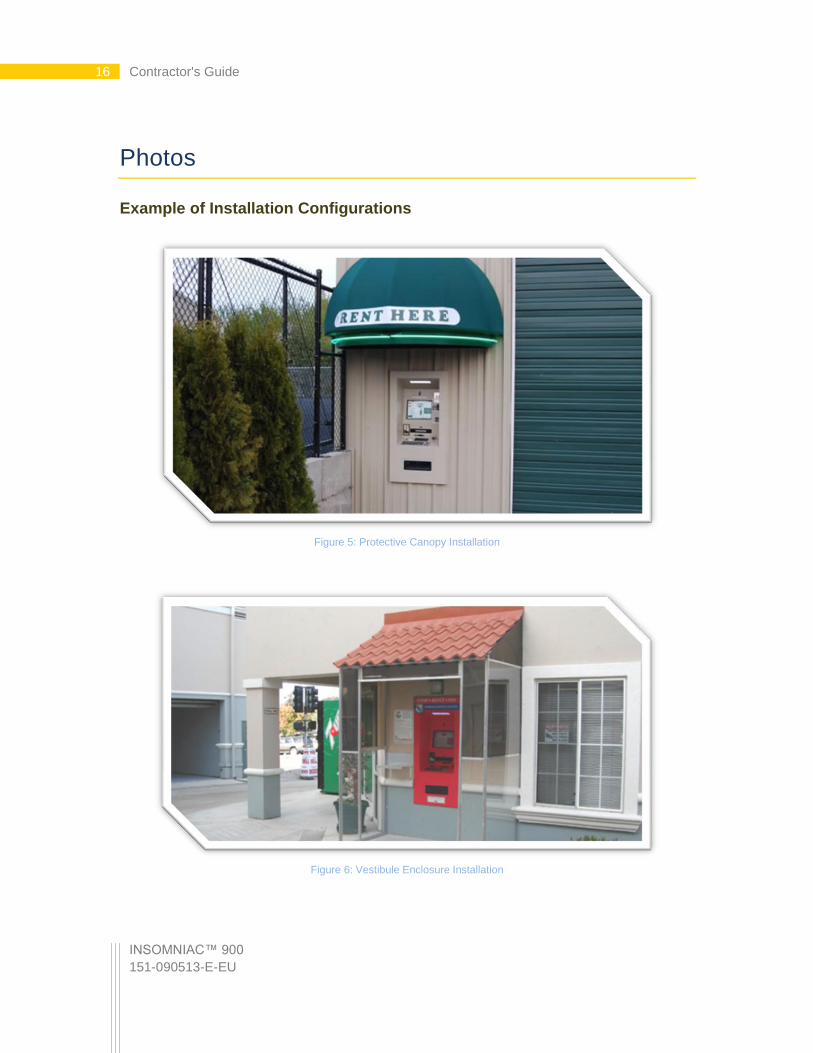
Protection from Weather Although the INSOMNIAC kiosk is designed for outdoor use, it should be protected from full weather
exposure. A canopy, awning or other covering should be above the kiosk to prevent direct rain and/or snow
contact. Care must be taken to install flashing where necessary to keep water from leaking where the kiosk
penetrates the wall. See Figure 5: Protective Canopy Installation on page 16, and Figure 6: Vestibule
Enclosure Installation on page 16 for photographic examples.

INSOMNIAC™ 900
151-090513-E-EU
8 Contractor's Guide
ADA Compliance
Accessibility Considerations
The primary issue addressed by The Americans with Disabilities Act (and corresponding local accessibility
code requirements), as applied to the kiosk, is provision for proper access to and from the INSOMNIAC 900
kiosk. This includes insuring the presence of an accessible route from public areas (including streets,
sidewalks and parking lots).
Installation Specifications
The kiosk is provided with adjustable legs to accommodate a variety of mounting heights. It is suggested
that the unit be installed at such a height so as to insure that the speakerphone box is lower than 48” AFF
(above finished floor); this will place the kiosk at a height that is accessible to an individual in a wheelchair
(for both forward and side approaches). In order to further accommodate wheelchair accessibility, units with
a lock dispenser should be installed so that access to the lock dispenser is a minimum of 15” AFF; this
complies with guidelines set forth by the ADA.
Power Requirements
Wired Power Specifications
The INSOMNIAC kiosk requires 110-120 VAC, 20 Amp, single-phase, three-wire un-switched power
receptacles. Wiring to the receptacle must include a third-wire earth-ground (conduit ground is not
acceptable.) The power cable is 10’ long and extends from a hole in the back, right-bottom corner of the
kiosk (when facing the kiosk from the front).
Extend a minimum of ¾” metal conduit from service panel to a 4” junction box located no further than 6’ from
the unit. Boxes can be flush mounted with concealed conduit for new construction, or boxes can be surface
mounted with exposed conduit for existing construction.
Backup Power Supply
An uninterruptible power supply (UPS), also known as an uninterruptible power source, or a battery backup,
is a device which maintains a continuous supply of electric power to connected equipment by supplying
power from a separate source when utility power is not available. In areas of the country that experience
frequent power disruptions (“Tornado Alley,” hurricane season, etc.), it is recommended that a UPS be
employed in order to minimize the effects of power outages.
When a power failure occurs, the UPS effectively switches from utility power to its own power source almost
instantaneously. The UPS, which is continuously connected to the protected load, draws energy from its
reserves, usually stored in lead-acid batteries, converting it to AC power.
In addition to providing protection against complete failure of the utility supply, a UPS also provides
protection against all common power problems, and for this reason it is also known as a power or line
“conditioner.”
Please consult with your electrical contractor for a unit appropriate to your facility.

9 Data Cable Requirements
Contractor's Guide
151-090513-E-EU
Data Cable Requirements
Always-On Internet Connectivity
The INSOMNIAC 900 must be connected to the computer (or network) upon which the facility’s
management software runs. If the facility has an “always-on” Internet connection (such as cable or DSL), the
network should be configured in order to allow OpenTech Alliance, Inc’s. Technical Support Specialists
access to the kiosk computer, through the Internet connection.
A contractor should run a CAT 5 data cable, in grounded conduit, from the location of the computer (or
network hub) that runs the management software, to a junction outlet box mounted a few feet from the kiosk.
The kiosk comes with a CAT 5 cable that extends 5’ from a hole in the back, right-bottom corner of the kiosk
(when facing the kiosk from the front).
On-Demand/”Dial-Up” Internet Connectivity
If the facility does not utilize an “always on” Internet connection to which the kiosk can be connected, a
standard POTS (“plain old telephone service”) telephone line should be terminated in a junction outlet box a
few feet from the kiosk. This line will be used by OpenTech Alliance, Inc’s. Technical Support Specialist to
access the kiosk computer, via modem, for diagnostics and service. This line can be the same line as the
speakerphone line described below, so long as it is a dedicated line to which there are no other devices
connected that will pick up when a call is received.
Plenum Ceiling Consideration Special considerations must be made if the kiosk will utilize wiring installed through a plenum ceiling. If the
area between the ceiling and the roof in a building is used for air return in a ventilation system, fire and
building codes normally require that special wire or conduit be used if wire is run through this area.
Fire Protection Consideration Installation of this kiosk in an existing facility with a new wall enclosure, may impact the sprinkler head cover
in this area, and require modification or addition of additional heads.
Heat Gain/Loss Consideration Installation of this kiosk in small areas with a lack of air circulation should take into consideration the heat
gain (build up of heat from operation of the equipment) and design the space accordingly.

INSOMNIAC™ 900
151-090513-E-EU
10 Contractor's Guide
11 INSOMNIAC 900 Specifications
Contractor's Guide
151-090513-E-EU
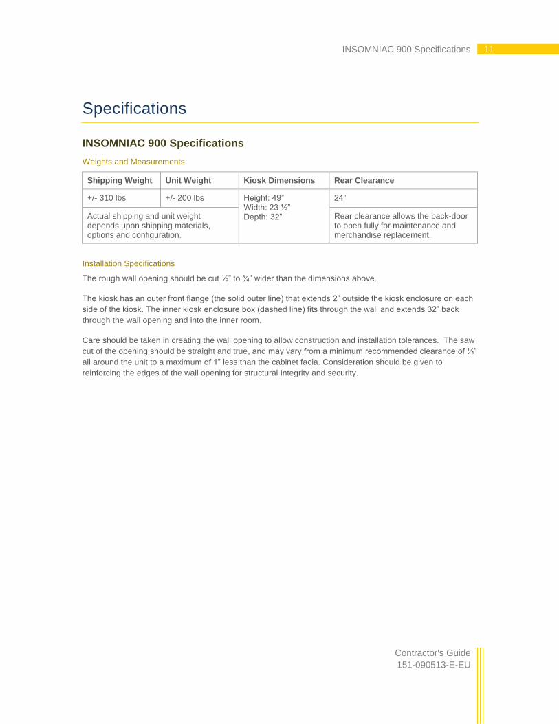
Specifications
INSOMNIAC 900 Specifications
Weights and Measurements
Shipping Weight Unit Weight Kiosk Dimensions Rear Clearance
+/- 310 lbs +/- 200 lbs Height: 49” Width: 23 ½” Depth: 32”
24”
Actual shipping and unit weight depends upon shipping materials, options and configuration.
Rear clearance allows the back-door to open fully for maintenance and merchandise replacement.
Installation Specifications
The rough wall opening should be cut ½” to ¾” wider than the dimensions above.
The kiosk has an outer front flange (the solid outer line) that extends 2” outside the kiosk enclosure on each
side of the kiosk. The inner kiosk enclosure box (dashed line) fits through the wall and extends 32” back
through the wall opening and into the inner room.
Care should be taken in creating the wall opening to allow construction and installation tolerances. The saw
cut of the opening should be straight and true, and may vary from a minimum recommended clearance of ¼”
all around the unit to a maximum of 1” less than the cabinet facia. Consideration should be given to
reinforcing the edges of the wall opening for structural integrity and security.

INSOMNIAC™ 900
151-090513-E-EU
12 Contractor's Guide
Drawings
Product & Installation Drawings
Overall Views
KIO
SK
VE
ST
IBU
LE P
LAN
text
KIO
SK
23.5"
24" 32" 24" Min. Clear.
6" - 10"
RE
CO
MM
EN
DE
D
SID
E C
LEA
RA
NC
E
8" EX
T.
WA
LL
7' - 0"
textR
OU
GH
OP
EN
ING
textK
IOS
K
FR
ON
T
ELE
VA
TIO
N
18" 50.5" RO
25" RO
23.5"
27.5"
18" 49"
WA
LL SE
CT
ION
wall sec
textK
IOS
K
32"24" M
in. Clear.
49"18"
AD
JUS
TA
BLE
BA
CK
LEG
S
PR
OV
IDE
D
8" EX
T.
WA
LL
EX
T. W
ALL
EX
T. W
ALL
TH
IS D
IME
NS
ION
WILL V
AR
Y
DE
PE
ND
ING
ON
INT
ER
IOR
FLO
OR
ELE
VA
TIO
N V
AR
IAT
ION
FR
OM
EX
TE
RIO
R F
LOO
R
ELE
VA
TIO
N
FIN
ISH
ED
FLO
OR
CE
ILING
CE
ILING
FIN
ISH
ED
FLO
OR
53"
Figure 1: Overall Views
13 Product & Installation Drawings
Contractor's Guide
151-090513-E-EU
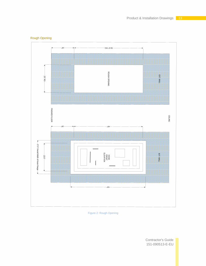
Rough Opening
27.5
" Ove
rall W
idth
of K
iosk F
lan
ge
text
RO
UG
H O
PE
NIN
Gte
xtK
IOS
K
FR
ON
T
EL
EV
AT
ION
18" 50.5" RO
25" R
O2
3.5
"
18" 49"
EX
T. W
AL
LE
XT
. WA
LL
CE
ILIN
G
FIN
ISH
ED
FL
OO
R
53"
Figure 2: Rough Opening
INSOMNIAC™ 900
151-090513-E-EU
14 Contractor's Guide
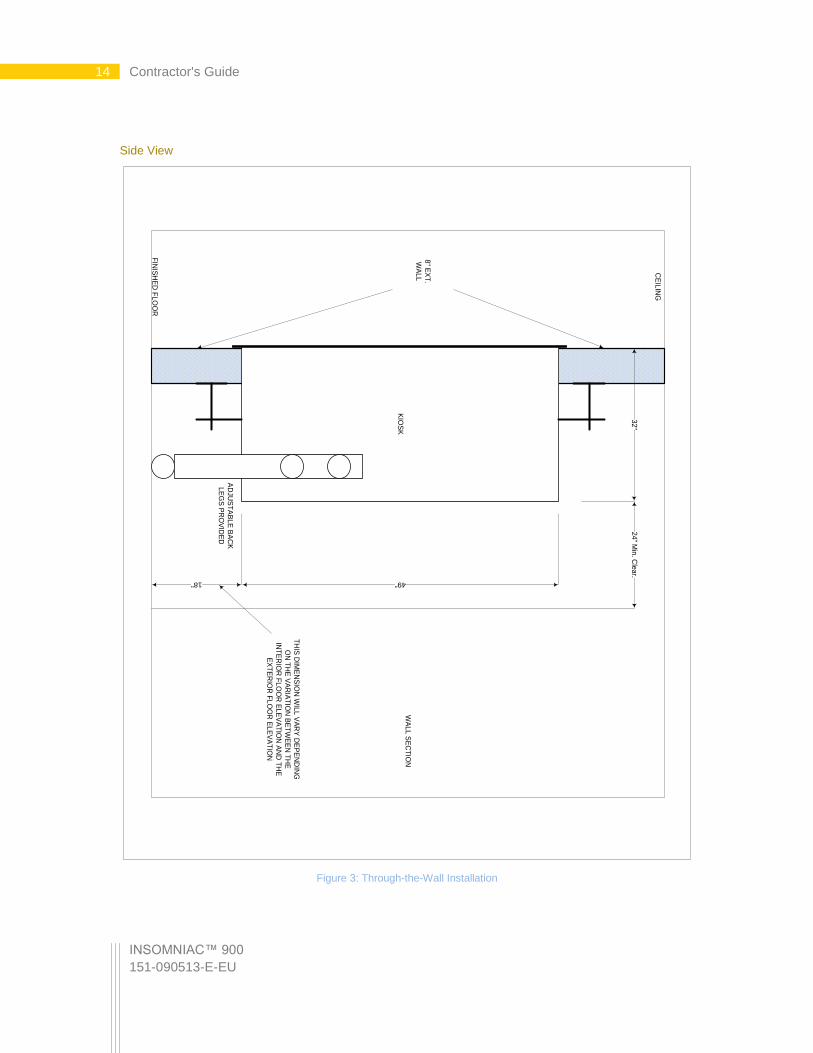
Side View
WA
LL
SE
CT
ION
wa
ll sec
KIO
SK
32
"2
4" M
in. C
lea
r.
49"18"
AD
JUS
TA
BL
E B
AC
K
LE
GS
PR
OV
IDE
D
8" E
XT
.
WA
LL
FIN
ISH
ED
FL
OO
R
CE
ILIN
G
TH
IS D
IME
NS
ION
WIL
L V
AR
Y D
EP
EN
DIN
G
ON
TH
E V
AR
IAT
ION
BE
TW
EE
N T
HE
INT
ER
IOR
FL
OO
R E
LE
VA
TIO
N A
ND
TH
E
EX
TE
RIO
R F
LO
OR
EL
EV
AT
ION
Figure 3: Through-the-Wall Installation

15 Product & Installation Drawings
Contractor's Guide
151-090513-E-EU
Enclosed in a Vestibule
KIOSK VESTIBULE PLAN
text
KIOSK
23.5"
24
"3
2"
24
" M
in.
Cle
ar.
6" - 10" RECOMMENDED SIDE
CLEARANCE
8" EXT. WALL
7' - 0"
Figure 4: Installation in an Enclosed Vestibule
INSOMNIAC™ 900
151-090513-E-EU
16 Contractor's Guide
Photos
Example of Installation Configurations
Figure 5: Protective Canopy Installation
Figure 6: Vestibule Enclosure Installation

17 Table of Figures
Contractor's Guide
151-090513-E-EU
Table of Figures
Figure 1: Overall Views ..................................................................................................................................................... 12 Figure 2: Rough Opening .................................................................................................................................................. 13 Figure 3: Through-the-Wall Installation ............................................................................................................................. 14 Figure 4: Installation in an Enclosed Vestibule .................................................................................................................. 15 Figure 5: Protective Canopy Installation ............................................................................................................................ 16 Figure 6: Vestibule Enclosure Installation ......................................................................................................................... 16
Table of Figures