ins-20606 - Paxton
28
Net2 Plus and Power supplies ins-20606 Paxton
Transcript of ins-20606 - Paxton

Net2 Plus and Power supplies
ins-20606
Paxton
1 2
43
1
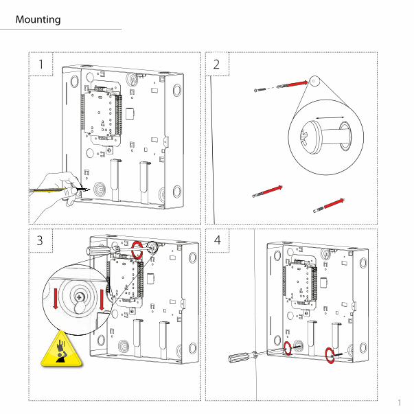
Mounting
1 2
Note: This mounting process applies to all types of cabinet and housing regardless of size, material or power supply included.
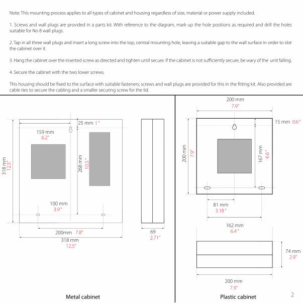
1. Screws and wall plugs are provided in a parts kit. With reference to the diagram, mark up the hole positions as required and drill the holes suitable for No 8 wall plugs.
2. Tap in all three wall plugs and insert a long screw into the top, central mounting hole, leaving a suitable gap to the wall surface in order to slot the cabinet over it.
3. Hang the cabinet over the inserted screw as directed and tighten until secure. If the cabinet is not su�ciently secure, be wary of the unit falling.
4. Secure the cabinet with the two lower screws.
This housing should be �xed to the surface with suitable fasteners; screws and wall plugs are provided for this in the �tting kit. Also provided are cable ties to secure the cabling and a smaller securing screw for the lid.
318
mm
318 mm12.5“
7.8“
3.18 “
10.5
“
1 “
12.5
”
200mm
159 mm
25 mm
81 mm
6.4 “162 mm
3.9 “
6.2“
100 mm
268
mm
0.6 “15 mm
6.6
“16
7 m
m
200
mm
7.9”
200 mm7.9”
200 mm7.9”
692.71”
74 mm2.9”
Metal cabinet Plastic cabinet
3
0V
Net2 p
lus
0V
0V
0V
0V
0V
PSU
OK
0V
0V
ARM
SENSE
N.C.
N.O1
2
COM
N.C.
N.O
COM
Data/D0
Clock/D1
CAT5 RS485Media
Detect
0V
10
TX RX
100
Data/D0
Clock/D1
Media Detect
10/100 Ethernet
N.C
.
N.O
CO
M
12V - 24V
12V
1
2
12V
LED
LED
LED
12V
LED
LED
LED
LED
EXITEXIT
PSU
12V D
C
12V D
C I
TX RXTX RXTX RXTX RX
0V
Net2 p
lus
0V
0V
0V
0V
0V
PSU
OK
0V
0V
ARM
SENSE
N.C.
N.O1
2
COM
N.C.
N.O
COM
Data/D0
Clock/D1
CAT5 RS485Media
Detect
0V
10
TX RX
100
Data/D0
Clock/D1
Media Detect
10/100 Ethernet
N.C
.
N.O
CO
M
12V - 24V
12V
1
2
12V
LED
LED
LED
12V
LED
LED
LED
LED
EXITEXIT
PSU
12V D
C
12V D
C I
TX RXTX RXTX RXTX RX
V21
V0
V21
V0
V42V0U
SP
V0
0V
0V
N.C.
N.O
COM
N.C.
N.O
COM
Data/D0
Clock/D1
0V
Data/D0
Clock/D1
12V
1
2
12V
LED
LED
LED
LED
LED
LED
12V D
C
Paxton
0V
0V
N.C.
N.O
COM
N.C.
N.O
COM
Data/D0
Clock/D1
0V
Data/D0
Clock/D1
12V
1
2
12V
LED
LED
LED
LED
LED
LED
12V D
C
Paxton
0V0V
0V
0V
N.C.
N.O
2
COM
N.C.
N.O
COM
Data/D0
Clock/D1
CAT5 RS485
0V
10
TX RX
100
Data/D0
Clock/D1
10/100 Ethernet
N.C
.
N.O
CO
M
12V - 24V
12V
1
2
12V
LED
LED
LED
12V
LED
LED
LED
LED
EXIT
12V D
C
12V D
C I
1PaxtonN
et2 plus
12V - 24V
10/100 Ethernet
RS485CAT5
TX RXTX RXTX RXTX RX
Net2 p
lus
TX RX
RS485CAT5
TX RXTX RX
12V
N.C
.
CO
M
0V
LED
EXIT
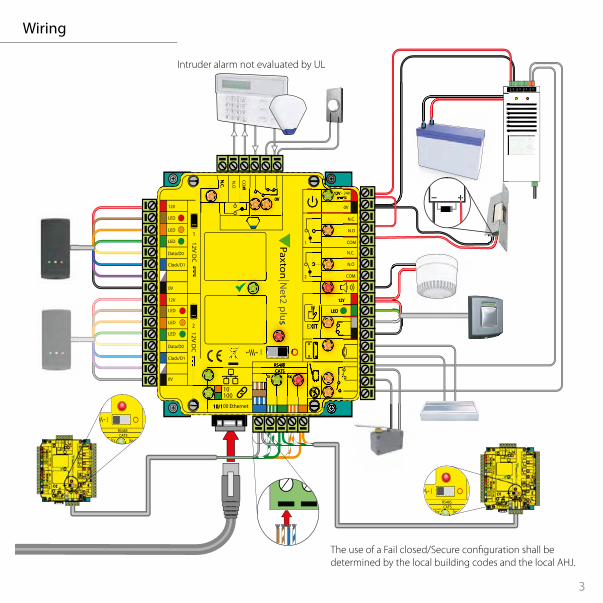
Wiring
Intruder alarm not evaluated by UL
The use of a Fail closed/Secure con�guration shall be determined by the local building codes and the local AHJ.
3 4
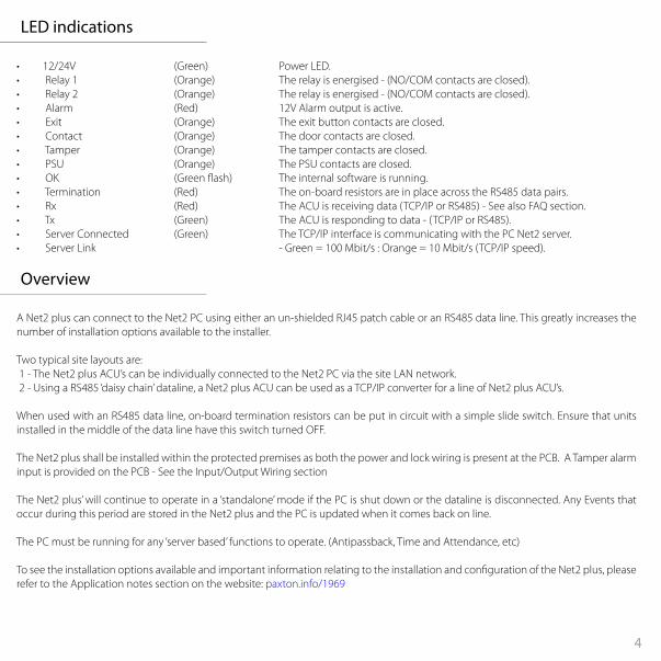
LED indications
Overview
• 12/24V (Green) Power LED.• Relay 1 (Orange) The relay is energised - (NO/COM contacts are closed).• Relay 2 (Orange) The relay is energised - (NO/COM contacts are closed).• Alarm (Red) 12V Alarm output is active.• Exit (Orange) The exit button contacts are closed.• Contact (Orange) The door contacts are closed.• Tamper (Orange) The tamper contacts are closed.• PSU (Orange) The PSU contacts are closed.• OK (Green �ash) The internal software is running.• Termination (Red) The on-board resistors are in place across the RS485 data pairs.• Rx (Red) The ACU is receiving data (TCP/IP or RS485) - See also FAQ section.• Tx (Green) The ACU is responding to data - (TCP/IP or RS485).• Server Connected (Green) The TCP/IP interface is communicating with the PC Net2 server.• Server Link - Green = 100 Mbit/s : Orange = 10 Mbit/s (TCP/IP speed).
A Net2 plus can connect to the Net2 PC using either an un-shielded RJ45 patch cable or an RS485 data line. This greatly increases the number of installation options available to the installer.
Two typical site layouts are: 1 - The Net2 plus ACU’s can be individually connected to the Net2 PC via the site LAN network. 2 - Using a RS485 ‘daisy chain’ dataline, a Net2 plus ACU can be used as a TCP/IP converter for a line of Net2 plus ACU’s.
When used with an RS485 data line, on-board termination resistors can be put in circuit with a simple slide switch. Ensure that units installed in the middle of the data line have this switch turned OFF.
The Net2 plus shall be installed within the protected premises as both the power and lock wiring is present at the PCB. A Tamper alarm input is provided on the PCB - See the Input/Output Wiring section
The Net2 plus’ will continue to operate in a ‘standalone’ mode if the PC is shut down or the dataline is disconnected. Any Events that occur during this period are stored in the Net2 plus and the PC is updated when it comes back on line.
The PC must be running for any ‘server based’ functions to operate. (Antipassback, Time and Attendance, etc)
To see the installation options available and important information relating to the installation and con�guration of the Net2 plus, please refer to the Application notes section on the website: paxton.info/1969

5
Input/Output wiring
Exit button When the Exit terminal is shorted to 0V, the Exit LED will illuminate and the ACU will operate Relay 1. The reader/exit button Green LED will �ash during this period. More than one exit button can be wired in parallel. Relay 1 will remain transferred while the short to 0V remains.
Door Bell - Relay 2 Pressing the bell button on the keypad will result in Relay 2 being energized for 1 second. A bell sounder can be controlled by wiring one of the bell feeds across COM / NO on the relay.
See Speci�cation table for Output Ratings
Door contactA NO switch may be �tted so that it is held closed while the door is shut.
When connected, Net2 will check the door position during access activity and will raise an Alarm in the event of a ‘Door Forced’ or ‘Door left open’ condition.
Tamper switchThe ACU supplied in a plastic housing has a ‘NO’ tamper switch �tted and pre-wired into the circuit board.
The Tamper LED will be ON when the switch is closed. Net2 will monitor the switch position and will raise an Alarm in the event of a ‘Tamper’ condition.
Connect to a UL listed burglar alarm unit for supervision.
PSU monitoringThe Net 2 software will monitor the contacts and will raise an alarm in the event of a ‘Mains Fail’ condition.
The PSU Led will be on when the ‘normally open’ contacts are ‘closed’.
682-528-US
682-493-US
Input 12-24V DC 3A
Relay Output 24V DC 4A
Alarm Output 12V DC 1A
Reader Output 11.5V DC 500mA
CircuitModel Voltage Current

5 6
Alarm sounder
Lock Wiring - Relay output
Panic hardware/ Fire Door Interface
Intruder alarm integration
This local alarm has a transistor ‘open drain’ output, (not a dry contact relay) and will switch 1A at 12V DC for a bell, light etc.
This local output can be turned on or o� for each type of alarm and can be con�gured to sound continuously or intermittently to distinguish between di�erent alarm types.
Resistive loading only
This is a ONE door controller using a dry contact relay
The lock is wired across 12V and COM. A link (12V to NO or NC) is required, depending on lock type (Fail Closed / Open). Fit the supplied diode across 12V and COM (Silver end to 12V ) to protect the relay contacts.
The dry relay contacts can be used to switch the power from an independent lock power supply. Wire the 12V to NC or NO and the lock to COM; the 0V from the supply is wired directly to the lock
The ACU supplied in a plastic housing has a ‘NO’ tamper switch �tted and pre-wired into the circuit board.
The Tamper LED will be ON when the switch is closed. Net2 will monitor the switch position and will raise an Alarm in the event of a ‘Tamper’ condition.
Connect to a UL listed burglar alarm unit for supervision.
A �re alarm system must be used to release all �re doors. External relay contacts are held closed by the �re alarm’s interface and will be dropped during an alarm condition. The system is fail safe as the door will release even if the cable burns through.
A dedicated port for input and output signals is provided when integrating a Net2 plus ACU with an alarm system.
Please see: AN1035 - Integrating Net2 with an intruder alarm system www.paxton.info/91 or call Technical Support for further information.
Arm - Arm con�rmation Push Button - Wire across 0V and Arm.Sense - Wire a voltage free loop across 0V and Sense to monitor the alarms current status.Set - Wire a voltage free loop across COM and N.O. or N.C. to provide a set signal for the alarm
Note: Burglar alarm integration has not been evaluated by UL
7
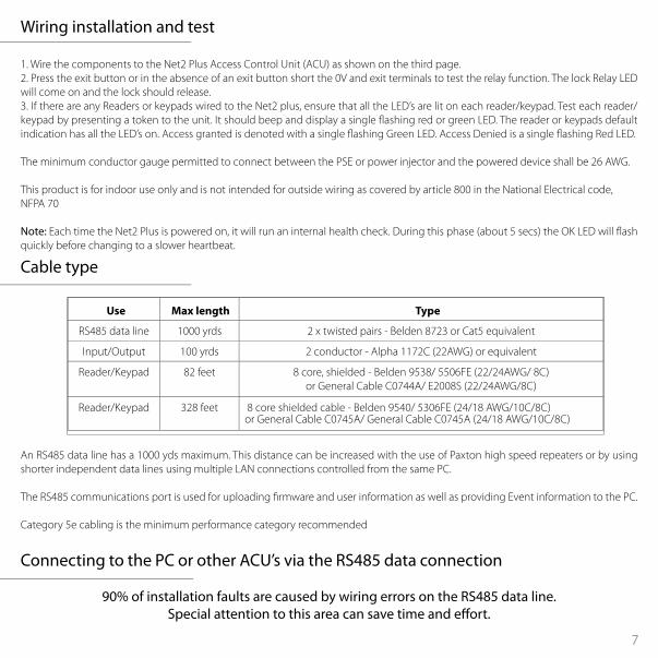
Cable type
Wiring installation and test
Connecting to the PC or other ACU’s via the RS485 data connection
An RS485 data line has a 1000 yds maximum. This distance can be increased with the use of Paxton high speed repeaters or by using shorter independent data lines using multiple LAN connections controlled from the same PC.
The RS485 communications port is used for uploading �rmware and user information as well as providing Event information to the PC.
Category 5e cabling is the minimum performance category recommended
1. Wire the components to the Net2 Plus Access Control Unit (ACU) as shown on the third page.2. Press the exit button or in the absence of an exit button short the 0V and exit terminals to test the relay function. The lock Relay LED will come on and the lock should release.3. If there are any Readers or keypads wired to the Net2 plus, ensure that all the LED’s are lit on each reader/keypad. Test each reader/keypad by presenting a token to the unit. It should beep and display a single �ashing red or green LED. The reader or keypads default indication has all the LED’s on. Access granted is denoted with a single �ashing Green LED. Access Denied is a single �ashing Red LED.
The minimum conductor gauge permitted to connect between the PSE or power injector and the powered device shall be 26 AWG.
This product is for indoor use only and is not intended for outside wiring as covered by article 800 in the National Electrical code, NFPA 70
Note: Each time the Net2 Plus is powered on, it will run an internal health check. During this phase (about 5 secs) the OK LED will �ash quickly before changing to a slower heartbeat.
90% of installation faults are caused by wiring errors on the RS485 data line. Special attention to this area can save time and e�ort.
RS485 data line 1000 yrds 2 x twisted pairs - Belden 8723 or Cat5 equivalent
Input/Output 100 yrds 2 conductor - Alpha 1172C (22AWG) or equivalent
Reader/Keypad 82 feet 8 core, shielded - Belden 9538/ 5506FE (22/24AWG/ 8C) or General Cable C0744A/ E2008S (22/24AWG/8C)
Reader/Keypad 328 feet 8 core shielded cable - Belden 9540/ 5306FE (24/18 AWG/10C/8C)or General Cable C0745A/ General Cable C0745A (24/18 AWG/10C/8C)
TypeMax lengthUse
7 8
TCP/IP and RS485 LED indication
Maintenance
RS485 data line resistance check
The Net2 plus performs two functions. It is an access control unit and also a TCP/IP RS485 converter. Information can pass across the PCB between the TCP/IP and RS485 data port but is not relevant to this ACU.
• Server Connected LED (Steady Green)This LED shows that the TCP/IP interface is active and receiving data from the Net2 PC server. This includes all data for other ACU’s that may be linked via the RS485 data port.
• Rx and Tx LED’sThese LED’s show the activity for this ACU only. It is not dependant on the source (TCP/IP or RS485). The Rx LED will �ash for all data being received and the Tx LED will only �ash when this unit responds to its own address.
It is advisable to ensure that any third party backup power supplies or recovery procedures are checked regularly to ensure that the operation of the Paxton system is not compromised.
1 - Short circuiting, mutilation or incineration of the cells must be avoided to prevent one or more of the following occurrences; Release of toxic materials, release of hydrogen and/or oxygen gas, rise in surface temperature.
2 - If a cell has leaked or vented the control unit must be replaced. The battery is not to be replaced
End of line termination - 120 ohm resistors must be linked across each data pair at the beginning AND end of the line. This can be done on many units with a switch or jumpers. If not, resistors are provided with the converter.
Reader & Data Cable Screens• Data cable screens and spare cores MUST be connected throughout.• Reader and keypad screens where provided, should be connected to the Black 0V terminal.
The data line must be wired in a single daisy chain. The data connection to the PC may be located at any position along the data line.
Power down all TCP/IP, USB and RS232 converters (individual and Net2 plus).
1. Check the resistance across each data pair is 60-80 ohms.
2. Check that there are no data line to screen shorts.
3. Check the screen of the data cable is continuous - this provides the 0V DC system reference
99
V0
802.3at
+-
+12V DC
2
0V
Clock/D1
COM
2
12V
LED
LED
LEDEXIT
12V DC
12V DC
PaxtonN
et2 plusN
et2 plus
N.C.
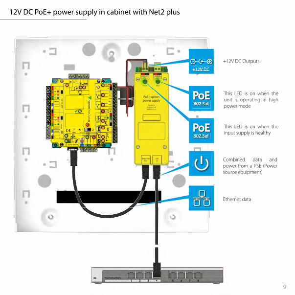
12V DC PoE+ power supply in cabinet with Net2 plus
+12V DC Outputs
Combined data and power from a PSE (Power source equipment)
This LED is on when the input supply is healthy
This LED is on when the unit is operating in high power mode
Ethernet data
9 10
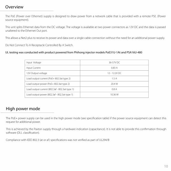
The PoE (Power over Ethernet) supply is designed to draw power from a network cable that is provided with a remote PSE. (Power source equipment).
This unit splits Ethernet data from the DC voltage. The voltage is available at two power connectors as 12V DC and the data is passed unaltered to the Ethernet Out port.
This allows a Net2 plus to receive its power and data over a single cable connection without the need for an additional power supply.
Do Not Connect To A Receptacle Controlled By A Switch.
UL testing was conducted with product powered from Phihong injector models PoE31U-1At and PSA16U-480
Overview
Input Voltage 36-57V DC
Input Current 0.83 A
12V Output voltage 12 - 12.2V DC
Load output current (PoE+ 802.3at type 2) 1.5 A
Load output power (PoE+ 802.3at type 2) 20.4 W
Load output current (802.3af - 802.3at type 1) 0.8 A
Load output power (802.3af - 802.3at type 1) 10.36 W
The PoE+ power supply can be used in the high power mode (see speci�cation table) if the power source equipment can detect this request for additional power.
This is achieved by the Paxton supply through a hardware indication (capacitance). It is not able to provide this con�rmation through software (DLL classi�cation).
Compliance with IEEE 802.3 (at or af ) speci�cations was not veri�ed as part of UL294/B
High power mode
11
Following the completed installation of this equipment, no further maintenance or testing is required. It is advisable to ensure that any third party backup power supplies or recovery procedures are checked regularly to ensure that the operation of the Paxton system is not compromised. This product is not suitable for retail sale. All warranties are invalid if this product is not installed by a trained technician.
Maintenance
1. Mount the cabinet as instructed on the �rst page. 2. Connect the network cable to PoE In.3. The Power LED will illuminate if power is available on this data line.4. The PoE+ LED will illuminate if the high power rating is available.5. 12V DC power is available at the two output connectors.6. Network data is available at ‘Ethernet Out’
Installation
11 1212
12V 7Ah
+-
13.8V DC
+-
+24V DC
24V AC/DC
!!V42
V0 V0V21
V0 V21
V0 V0
USP
Data/D0
Clock/D1
0V
Data/D0
Clock/D1
1
2
12V
LED
LED
LED
LED
LED
LED
12V DC
12V DC I
PaxtonN
et2 plusN
et2 plus
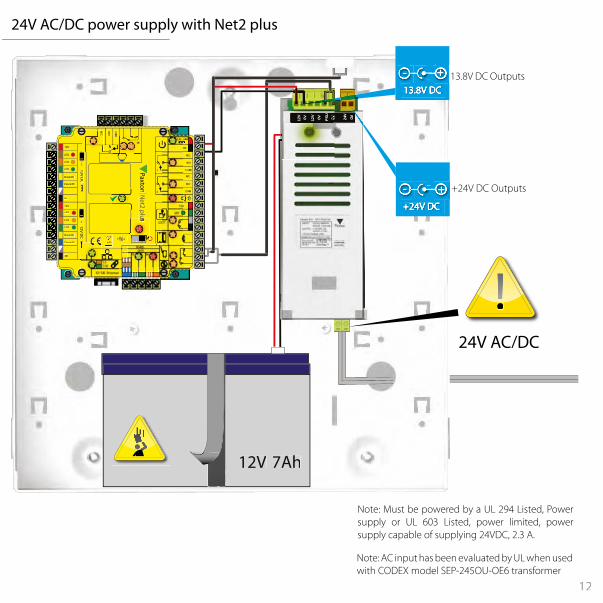
24V AC/DC power supply with Net2 plus
Note: Must be powered by a UL 294 Listed, Power supply or UL 603 Listed, power limited, power supply capable of supplying 24VDC, 2.3 A.
13.8V DC Outputs
+24V DC Outputs
Note: AC input has been evaluated by UL when used with CODEX model SEP-245OU-OE6 transformer
13
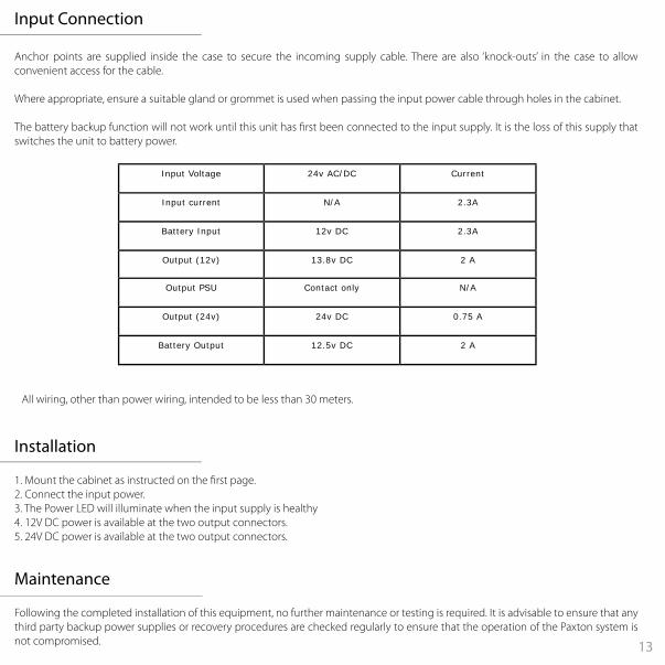
Anchor points are supplied inside the case to secure the incoming supply cable. There are also ‘knock-outs’ in the case to allow convenient access for the cable.
Where appropriate, ensure a suitable gland or grommet is used when passing the input power cable through holes in the cabinet.
The battery backup function will not work until this unit has �rst been connected to the input supply. It is the loss of this supply that switches the unit to battery power.
1. Mount the cabinet as instructed on the �rst page. 2. Connect the input power.3. The Power LED will illuminate when the input supply is healthy4. 12V DC power is available at the two output connectors.5. 24V DC power is available at the two output connectors.
Input Connection
Installation
Following the completed installation of this equipment, no further maintenance or testing is required. It is advisable to ensure that any third party backup power supplies or recovery procedures are checked regularly to ensure that the operation of the Paxton system is not compromised.
Maintenance
All wiring, other than power wiring, intended to be less than 30 meters.
Input Voltage 24v AC/DC Current
Input current N/A 2.3A
Battery Input 12v DC 2.3A
Output (12v) 13.8v DC 2 A
Output PSU Contact only N/A
Output (24v) 24v DC 0.75 A
Battery Output 12.5v DC 2 A

13 1414
V21
V0 V21
V0
V42
V0
USP
V0
12V 7Ah
V21
V0 V21
V0
V42
V0
USP
V0
12V 7Ah
Status Lights
Green This LED is on when the input supply is healthy.
Red This LED is on when the input supply has failed - Power is being supplied by the battery.
15
12V
24V
!!
V21
V0 V21
V0
V42
V0
USP
V0
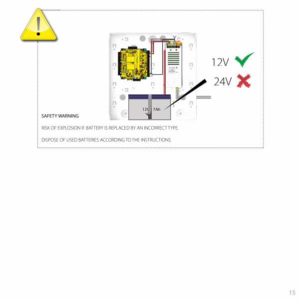
12V 7AhSAFETY WARNING
RISK OF EXPLOSION IF BATTERY IS REPLACED BY AN INCORRECT TYPE.
DISPOSE OF USED BATTERIES ACCORDING TO THE INSTRUCTIONS.
15 16
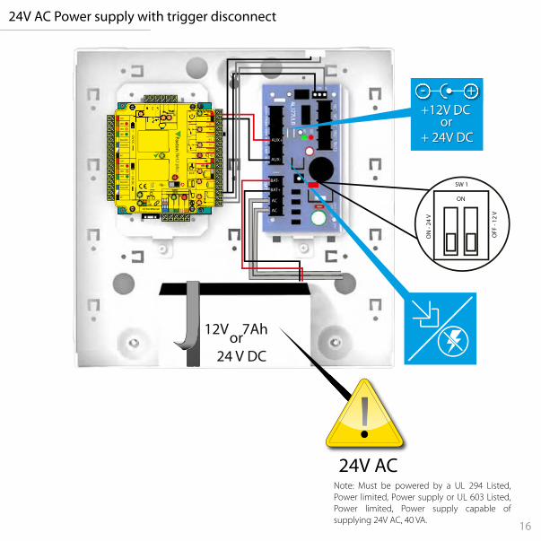
24V AC Power supply with trigger disconnect
0V0V
0V
N.C.
N.O
2
COM
N.C.
N.O
COM
Data/D0
Clock/D1
0V
Data/D0
Clock/D1
N.O
12V - 24V
12V
1
2
12V
LED
LED
LED
12V
LED
LED
LED
LED
12V DC
12V DC
1Paxton
12V - 24V
12V
LED
V0
12V 7Ahor24 V DC
24V AC
!!
+-+12V DC
+ 24V DC
+12V DC or
ON
ON
- 24
V
OFF
- 12
V
SW 1
AUX+
AUX-
BAT-
BAT+
AC
AC
Note: Must be powered by a UL 294 Listed, Power limited, Power supply or UL 603 Listed, Power limited, Power supply capable of supplying 24V AC, 40 VA.
17
12V 7Ah
LOCK +
COM -
AUX +
AUX -
BAT +
BAT -
AC
AC
TRG1
TRG2
0V0V
0V
N.C.
N.O
2
COM
N.C.
N.O
COM
Data/D0
Clock/D1
0V
10100
Data/D0
Clock/D1
N.O
12V - 24V
12V
1
2
12V
LED
LED
LED
12V
LED
LED
LED
LED
12V DC
12V DC
1Paxton
12V - 24V
12V
LED
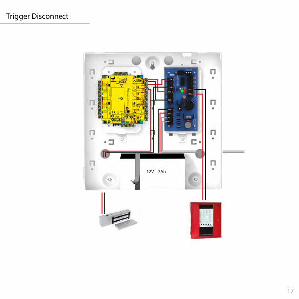
Trigger Disconnect
17 18
Overview
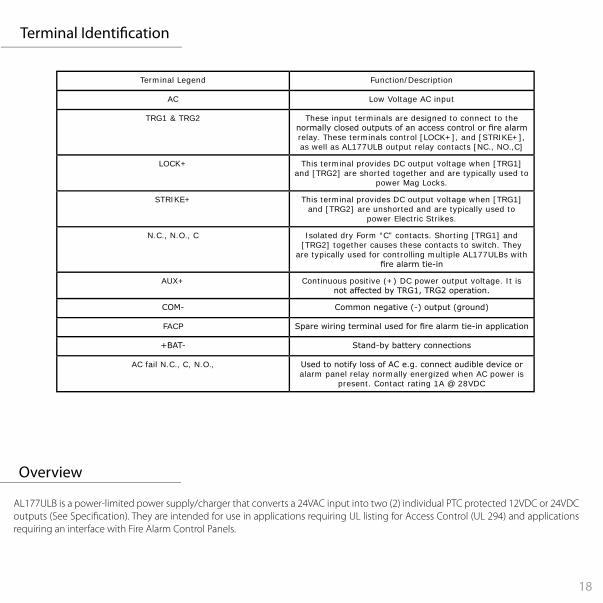
AL177ULB is a power-limited power supply/charger that converts a 24VAC input into two (2) individual PTC protected 12VDC or 24VDC outputs (See Speci�cation). They are intended for use in applications requiring UL listing for Access Control (UL 294) and applications requiring an interface with Fire Alarm Control Panels.
Terminal Legend Function/Description
AC Low Voltage AC input
TRG1 & TRG2 These input terminals are designed to connect to the normally closed outputs of an access control or fire alarm relay. These terminals control [LOCK+], and [STRIKE+], as well as AL177ULB output relay contacts [NC., NO.,C]
LOCK+ This terminal provides DC output voltage when [TRG1] and [TRG2] are shorted together and are typically used to
power Mag Locks.
STRIKE+ This terminal provides DC output voltage when [TRG1] and [TRG2] are unshorted and are typically used to
power Electric Strikes.
N.C., N.O., C Isolated dry Form “C” contacts. Shorting [TRG1] and [TRG2] together causes these contacts to switch. They
are typically used for controlling multiple AL177ULBs with fire alarm tie-in
AUX+ Continuous positive (+) DC power output voltage. It is not affected by TRG1, TRG2 operation.
COM- Common negative (-) output (ground)
FACP Spare wiring terminal used for fire alarm tie-in application
+BAT- Stand-by battery connections
AC fail N.C., C, N.O., Used to notify loss of AC e.g. connect audible device or alarm panel relay normally energized when AC power is
present. Contact rating 1A @ 28VDC
Terminal Identi�cation

19
Maintenance
Following the completed installation of this equipment, no further maintenance or testing is required. It is advisable to ensure that any third party backup power supplies or recovery procedures are checked regularly to ensure that the operation of the Paxton system is not compromised. This product is not suitable for retail sale. All warranties are invalid if this product is not installed by a trained technician.
Installation
The AL177ULB should be installed in accordance with article 760 of The National Electrical code (NFPA 70) or The National Fire Alarm Code (NFPA 72) as well as all applicable Local Codes
1. Mount the cabinet as instructed on the �rst page.
2. Mount the AL177ULB in the desired location/enclosure.
3. Connect 24VAC, 40VA transformer to the terminals marked [AC, AC].Use 18 AWG or larger for all power connections (Battery, DC, Output).Use 22 AWG to 18 AWG for power-limited circuits (trigger inputs, dry outputs).
Keep power-limited wiring separate from non power-limited wiring (AC input, Battery Wires). Minimum 0.25” spacing must be provided.
4.Set the AL177ULB to the desired DC output voltage by setting switch SW1 [1&2] to the appropriate position.
5. Measure output voltage before connecting devices. This helps avoiding potential damage.
6. Connect battery to the terminals marked [+BAT-] on the unit (battery leads included). Use two (2) 12VDC batteries connected in series for 24VDC operation.
Note: for Access control applications batteries are optional. When batteries are not used, a loss of AC will result in the loss of the output voltage. when the use of stand-buy batteries is desired, they must be lead acid or gel type.
7. Connect appropriate signalling noti�cation devices to AC fail supervisory relay outputs. Note: To meet UL requirements, AC supervisory outputs must be connected to the zone of Alarm Control Panel or to visual AC trouble indicator.
Output VDC SW1Switch position 1 & 2
12 OFF
24V ON
Input Output
24V AC 40VA12V DC 1.75A
or24V DC 0.9A
19 2020
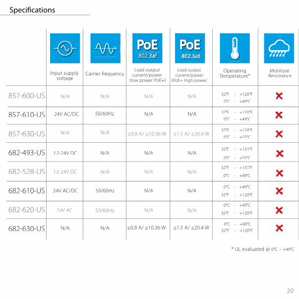
Input supply voltage
Load output current/power
(PoE+ High power)
OperatingTemperature*
* UL evaluated at 0°C - +49°C
Moisture Resistance
Load output current/power
(low power PoE+)Carrier frequency
802.3at
857-600-US
857-610-US
857-630-US
682-493-US
682-528-US
682-610-US
682-620-US
682-630-US
12-24V DC N/A
12-24V DC
N/A N/A
0°C - +55°C
32°F - +131°F
0°C - +55°C
32°F - +131°F
N/A N/A
N/A N/A
N/A N/A
50/60Hz24V AC/DC
0°C - +49°C
32°F - +120°F
0°C - +49°C
32°F - +120°F≤1.5 A/ ≤20.4 W≤0.8 A/ ≤10.36 WN/A N/A
N/A N/A 32°F - +120°F
N/A
N/A N/A50/60Hz24V AC/DC0°C - +49°C
32°F - +120°F
N/A N/A50/60Hz24V AC0°C - +49°C
32°F - +120°F
0°C - +49°C 32°F - +120°F≤1.5 A/ ≤20.4 W≤0.8 A/ ≤10.36 WN/A N/A
0°C - +49°C
Speci�cations
21
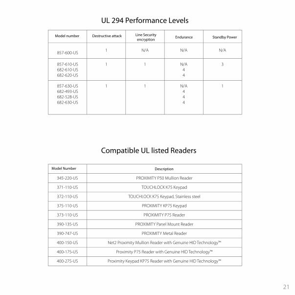
345-220-US PROXIMITY P50 Mullion Reader
371-110-US TOUCHLOCK K75 Keypad
372-110-US TOUCHLOCK K75 Keypad, Stainless steel
375-110-US PROXIMITY KP75 Keypad
373-110-US PROXIMITY P75 Reader
390-135-US PROXIMITY Panel Mount Reader
390-747-US PROXIMITY Metal Reader
400-150-US Net2 Proximity Mullion Reader with Genuine HID Technology™
400-175-US Proximity P75 Reader with Genuine HID Technology™
400-275-US Proximity Keypad KP75 Reader with Genuine HID Technology™
Model Number Description
Compatible UL listed Readers
857-600-US 1 N/A N/A N/A
857-610-US682-610-US682-620-US
1 1 N/A44
3
857-630-US682-493-US682-528-US682-630-US
1 1 N/A444
1
Destructive attackModel number Line Security encryption Endurance Standby Power
UL 294 Performance Levels
21 22
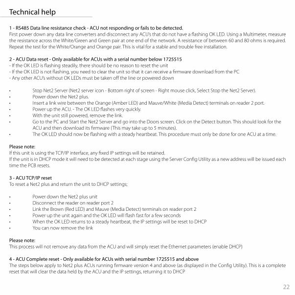
1 - RS485 Data line resistance check - ACU not responding or fails to be detected.First power down any data line converters and disconnect any ACU’s that do not have a �ashing OK LED. Using a Multimeter, measure the resistance across the White/Green and Green pair at one end of the network. A resistance of between 60 and 80 ohms is required. Repeat the test for the White/Orange and Orange pair. This is vital for a stable and trouble free installation.
2 - ACU Data reset - Only available for ACUs with a serial number below 1725515 - If the OK LED is �ashing steadily, there should be no reason to reset the unit- If the OK LED is not �ashing, you need to clear the unit so that it can receive a �rmware download from the PC- Any other ACU’s without OK LEDs must be taken o� the line or powered down
• Stop Net2 Server (Net2 server icon - Bottom right of screen - Right mouse click, Select Stop the Net2 Server).• Power down the Net2 plus.• Insert a link wire between the Orange (Amber LED) and Mauve/White (Media Detect) terminals on reader 2 port.• Power up the ACU. - The OK LED �ashes very quickly.• With the unit still powered, remove the link.• Go to the PC and Start the Net2 Server and go into the Doors screen. Click on the Detect button. This should look for the ACU and then download its �rmware (This may take up to 5 minutes).• The OK LED should now be �ashing with a steady heartbeat. This procedure must only be done for one ACU at a time.
Please note:If this unit is using the TCP/IP interface, any �xed IP settings will be retained.If the unit is in DHCP mode it will need to be detected at each stage using the Server Con�g Utility as a new address will be issued each time the PCB resets. 3 - ACU TCP/IP resetTo reset a Net2 plus and return the unit to DHCP settings;
• Power down the Net2 plus unit• Disconnect the reader on reader port 2• Link the Brown (Red LED) and Mauve (Media Detect) terminals on reader port 2• Power up the unit again and the OK LED will �ash fast for a few seconds• When the OK LED returns to a steady heartbeat, the IP settings will be reset to DHCP• You can now remove the link
Please note:This process will not remove any data from the ACU and will simply reset the Ethernet parameters (enable DHCP) 4 - ACU Complete reset - Only available for ACUs with serial number 1725515 and aboveThe steps below apply to Net2 plus ACUs running �rmware version 4 and above (as displayed in the Con�g Utility). This is a complete reset that will clear the data held by the ACU and the IP settings, returning it to DHCP
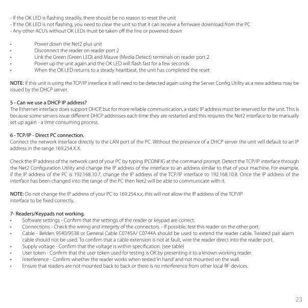
Technical help
23
7- Readers/Keypads not working.• Software settings - Con�rm that the settings of the reader or keypad are correct. • Connections - Check the wiring and integrity of the connectors. - If possible, test this reader on the other port. • Cable - Belden 9540/9538 or General Cable C0745A/ C0744A should be used to extend the reader cable. Twisted pair alarm
cable should not be used. To con�rm that a cable extension is not at fault, wire the reader direct into the reader port.• Supply voltage - Con�rm that the voltage is within speci�cation. (see table) • User token - Con�rm that the user token used for testing is OK by presenting it to a known working reader.• Interference - Con�rm whether the reader works when tested ‘in hand’ and not mounted on the wall. • Ensure that readers are not mounted back to back or there is no interference from other local RF devices.
- If the OK LED is �ashing steadily, there should be no reason to reset the unit- If the OK LED is not �ashing, you need to clear the unit so that it can receive a �rmware download from the PC- Any other ACU’s without OK LEDs must be taken o� the line or powered down
• Power down the Net2 plus unit• Disconnect the reader on reader port 2• Link the Green (Green LED) and Mauve (Media Detect) terminals on reader port 2• Power up the unit again and the OK LED will �ash fast for a few seconds• When the OK LED returns to a steady heartbeat, the unit has completed the reset
NOTE: If this unit is using the TCP/IP interface it will need to be detected again using the Server Con�g Utility as a new address may be issued by the DHCP server.
5 - Can we use a DHCP IP address?The Ethernet interface does support DHCP, but for more reliable communication, a static IP address must be reserved for the unit. This is because some servers issue di�erent DHCP addresses each time they are restarted and this requires the Net2 interface to be manually set up again - a time consuming process.
6 - TCP/IP - Direct PC connection.Connect the network interface directly to the LAN port of the PC. Without the presence of a DHCP server the unit will default to an IP address in the range 169.254.X.X.
Check the IP address of the network card of your PC by typing IPCONFIG at the command prompt. Detect the TCP/IP interface through the Net2 Con�guration Utility and change the IP address of the interface to an address similar to that of your machine. For example, if the IP address of the PC is 192.168.10.7, change the IP address of the TCP/IP interface to 192.168.10.8. Once the IP address of the interface has been changed into the range of the PC then Net2 will be able to communicate with it.
NOTE: Do not change the IP address of your PC to 169.254.x.x, this will not allow the IP address of the TCP/IPinterface to be �xed correctly.

23 24
+27 (0) 21 4276691
paxton.support
+31 (0)76 3333 999
paxton.benelux.support
+44 (0)1273 811011
paxton.support
+49 (0) 251 2080 6900
paxton.gmbh.support
+44 (0)1273 811011
paxton.support
8000 3570 3783
paxton.support
+33 (0)1 57 32 93 56
paxton.support
877.438.7298
usapaxton.support
+52 55 5351 3667
paxton.soporte
+57 1508 8198
paxton.soporte
+32 (0) 78485147
paxton.benelux.support

25
North America:-
To comply as a UL listed installation, the following conditions must apply:-
Software features and functions have not been evaluated by UL.
Server based functions (Antipassback, Time and Attendance, etc) have not been evaluated by UL and cannot be used for UL 294 installations.
The use of Wiegand readers and the con�guration software has not been evaluated by 'UL'
Wiring: - Where an equivalent cable / wire is used it must be ' UL Listed ' All interconnecting devices must be UL Listed.
Exit buttons - A UL listed 'push to make' button must be used.Door contact - A UL listed 'Normally Open' (N.O.) Switch must be used.Tamper alarm - Connect to a UL listed burglar alarm unit for supervision.Alarm sounder - Connections to this alarm output have not been evaluated by UL for burglar alarm use.Break glass- A UL listed break glass must be used.Fire door interface - This feature has not been evaluated by 'UL' and must not be used in UL-294 installations.Intruder alarm integration - This feature has not been evaluated by 'UL' and must not be used in UL-294 installations.
Product Compliance and limitations
Wiring methods shall be in accordance with the National Electrical Code (ANSI/NFPA70), local codes, and the authorities having jurisdiction.
For CAN/CSA installations, terminals, leads and wiring methods must comply with CSA, C22.1, Canadian electrical code, Part 1, safety standards for electrical installations.
The use of any add-on, expansion, memory or other module manufactured or supplied by the manufacturer’s representative will invalidate the CAN/CSA certi�cation.
This device complies with Industry Canada licence-exempt RSS standard(s). Operation is subject to the following two conditions: (1) this device may not cause interference, and (2) this device must accept any interference, including interference that may cause undesired operation of the device.
This device complies with Part 15 of the FCC Rules. Operation is subject to the following two conditions: (1) this device may not cause harmful interference, and (2) this device must accept any interference received, including interference that may cause undesired operation. Changes or modi�cations not expressly approved by the party responsible for compliance could void the user's authority to operate the equipment.
Class A digital devices.This equipment has been tested and found to comply with the limits for a Class A digital device, pursuant to part 15 of the FCC Rules. These limits are designed to provide reasonable protection against harmful interference when the equipment is operated in a commercial environment. This equipment generates, uses, and can radiate radio energy and, if not installed and used in accordance with the instruction manual, may cause harmful interference to radio communications. Operation of this equipment in a residential area is likely to cause harmful interference in which case the user will be required to correct the interference at his own expense.
FCC Compliance
25 26
Conformité et limitations du produit
Pour que l'installation répond aux normes UL, les conditions suivantes sont applicables.
Le pouvoir doit être fourni par une alimentation DC séparée. Un contrôle d’accès UL (ou alarme) classe 2, puissance limitée, source d’énergie capable de 4 heures en veille doit être utilisé. Ceci est branché sur les bornes 0V et 12/24V et le câble �xé avec des attaches de câble fournis.
Fonctions logicielles n’ont pas été évalués par UL.
Les méthodes de câblage doivent être en accord avec le code nation électrique (ANSI/NFPA70), codes locaux et les autorités ayant la juridiction.
Pour les installation CAN/CSA, les terminaux, câbles et méthodes de câblage doivent être en accord avec CSA, C22.1, code électrique canadien, Partie 1, standards de sécurité pour les installations électriques.
L’utilisation de tout rajout, extension, mémoire ou module fabriqué ou fourni par le représentant du fabricant invalidera la certi�cation CAN/CSA
Ce dispositif est conforme au(x) standards RSS de l’industrie Canadienne sans-licence. Le fonctionnement est soumis aux deux conditions suivantes : (1) ce dispositif ne doit pas créer d’interférences nuisibles et (2) ce dispositif doit accepter toute interférence reçue, y compris des interférences qui peuvent causer un fonctionnement non souhaité.
Les fonctions serveur (Antipassback, Pointage, etc.) n’ont pas été évalué par l’UL et ne peuvent pas être utilisé pour les installations UL294.
L’utilisation des lecteurs Wiegand et le logiciel de con�guration n’ont pas été évalués par ‘UL’
Câblage: - Quand un cable équivalent est utilisé, il doit être ‘listé UL’Tout appareil d’interconnexion doit être listé UL
Les boutons de sortie - A UL ‘pousser à faire’ bouton doit être utilisé.Contact de porte - A UL ‘Normalement ouvert »(NO) commutateur doit être utilisé.Autoprotection - Connectez-vous à une unité d’alarme antivol UL pour la supervision.Alarme sonore - Connexions à cette sortie d’alarme n’ont pas été évalués par l’UL pour l’utilisation de système d’alarme.Brise-glace - Un UL verre de rupture doit être utilisé.Interface Porte coupe-feu - Cette fonction n’a pas été évaluée par ‘UL’ et ne doit pas être utilisé dans les installations UL-294.L’intégration d’alarme anti-intrusion - Cette fonction n’a pas été évaluée par ‘UL’ et ne doit pas être utilisé dans les installations UL-294.
Ce dispositif est conforme à la section 15 du règlement de la FCC. Le fonctionnement est soumis aux deux conditions suivantes : (1) ce dispositif ne doit pas créer d'interférences nuisibles et (2) ce dispositif doit accepter toute interférence reçue, y compris des interférences qui peuvent causer un fonctionnement non souhaité. Tout changement ou modi�cation non agréé par la partie responsable de la mise en conformité peut entraîner une interdiction d'utilisation de l'équipement.
Appareils numériques de classe A.Cet appareil a été testé et a été trouvé conforme avec les limites pour un appareil numérique de Classe B, en vertu de la Partie 15 des règles FCC. Ces limites sont conçues pour fournir une protection raisonnable contre des interférences nuisibles dans une installation résidentielle. L’appareil génère, utilise et peut émettre une énergie de fréquence radio et, s’il n’est pas installé et utilisé en accord avec les instructions, peut causer des interférences nuisibles aux communications radio. L’opération de cet équipement dans une zone résidentielle créera probablement des interférences nuisibles dans quel cas l’utilisateur sera requis pour corriger l’interférence à ses frais.
Conformité FCC

26/03/2020© Paxton Ltd 1.0.7
Assembled in America.Comprised of US and UK manufactured components