
INROADS XM TEMPLATE LIBRARY - SUNY Polytechnic...
108
COURSE 330 INROADS XM–TEMPLATE LIBRARY July 2010 NEW YORK STATE DEPARTMENT OF TRANSPORTATION
Transcript of INROADS XM TEMPLATE LIBRARY - SUNY Polytechnic...

COURSE 330
INROADS XM–TEMPLATE LIBRARY
July 2010
NEW YORK STATE DEPARTMENT OF TRANSPORTATION

i
InRoads Template Library

ii
Course Prerequisites The following is a list of requirements that must be met by a student before entering class:
Should have MicroStation experience
Introduction to InRoads XM—Version 8.09; or InRoads XM Data and Environment
Horizontal Alignments and Cross Sections Course
Vertical Alignments and Profiles Course
Should have experience with InRoads Alignments

iii
InRoads Template Library
Disclaimer: The Material within this book is for the purpose of teaching the use of InRoads XM as a Design Tool. Please refer to Design Procedural and Standards Manuals, such as the “Highway Design Manual” and others, for Specific Guidance on your Project’s Design. Any representation of Design Documents contained within are subject to change. Please, consult latest version of Design Documents.
iv
Table of Contents
Course Prerequisites
Chapter 1: Getting Started
Open MicroStation Design File
Open InRoads, Create Project Default, Open InRoads Files
Create Project Template Library File from Seed Folder
Set the Active Surface
Chapter 2: Create Template Dialog Box
Template Library Area
Current Template Window
Template Preview Window
Dynamic Settings
Point Name List
Template Library Menu Bar
Template Library Organizer
Chapter 3: Point Constraints and Components Template Points—Point Names Template Components Point Constraints Manipulating Points and Point Constraints Deleting and Adding Point Constraints Point Labels Chapter 4: Create Components Component Slopes and Distances Component Names Create Simple Components
Edit Template Point Names
Merge Components
Create Constrained and Unconstrained Components

v
InRoads Template Library

vi
Table of Contents
Chapter 5: Create Templates
Create new Template
Build Template from Components
Check Point Connectivity
Merge Components
Rename Components
Edit Components
Chapter 6: End Conditions
End Conditions Provided in Standard Template Library
End Conditions’ Settings and Properties
Test End Conditions
Add End Condition Components to Template
Chapter 7: LAB
Open New MicroStation File, Restart InRoads
Create a Urban Template with Curbs, Sidewalks, and Utility Strips
Edit Template Points End Condition Priorities

InRoads Template Library
1 - 1
Getting Started
1- 2
Chapter 1
Chapter 1
Getting Started
In this chapter you will create a Template Library File from a Seed Document. You will open a MicroStation Design File, open InRoads, Create Project Defaults, and Open InRoads Files.
InRoads Template Library
1 - 3

Getting Started
1- 4
Chapter 1
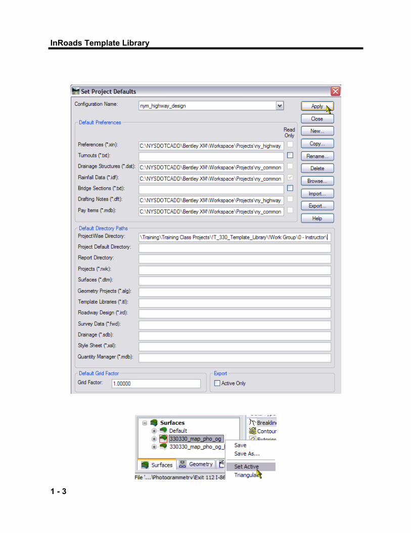
3) Open InRoads, Create the Project Default and Open InRoads Files
330330_fea_rwy.alg 330330_fea_rwy.itl (Copy of Standard .itl)
The instructor will give directions on what log-in to use and where the lab files are located in ProjectWise Open the MicroStation design file 330330_fea_rwy_tmp.dgn
1) Open the MicroStation Design File.
Create the Project Defaults by setting the Default Directory Path, ProjectWise Directory, to the class Student Folder. Open the InRoads files from your Student Folder.
Open the Original Ground DTM’s as ―Read Only‖ f rom the Photogrammetry Folder.
330330_map_pho_og.dtm 330330_map_pho_og_b.dtm
4) Set the Active Surface
Copy nym_standard.itl from Seed Folder to Student Folder. Rename the Template Library file, 330330_fea_rwy.itl
2) Create Project Template Library File from Seed Folder
Set Active Surface to 330330_map_pho_og.dtm.

InRoads Template Library
2-1

Create Template Dialog Box
2- 2
Chapter 2
Chapter 2
Create Template Dialog Box
This chapter will introduce you to the Create Template Dialog Box. Create Template remains under InRoads “Modeler” tools. However, the Create Template command has been rewritten. The file extension for Template Libraries is *.itl. Only one Template Library can be open at a time. The Create Template dialog box is the primary place for creating and editing templates. In this chapter, the various parts of the Create Template Dialog Box will be explored. Later chapters will explain in detail how templates are created.

InRoads Template Library
2-3

Create Template Dialog Box
2- 4
Chapter 2
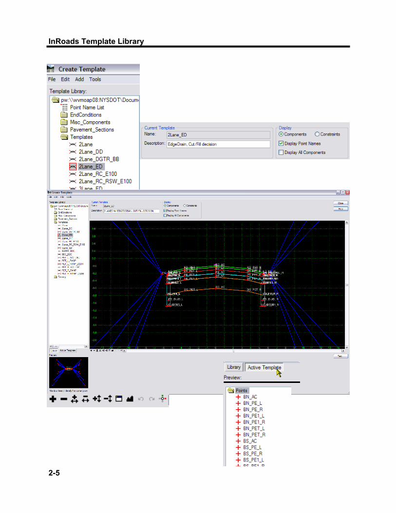
Open the Create Template dialog box, on the left side of the dialog box is the Template Library area. The Template Library area contains a “Windows like” folder structure. The root folder is the name and location of the InRoads Template Library that is currently open. Double click on the Root Folder, which is the name and location of the InRoads Template Library which is currently open. To navigate the folder structure, double click the folders you want to open or close. Inside any folder you can create and organize your templates and subfolders. The organization of the folder structure is user definable. The folder structure also supports common Window functions, such as drag and drop, cut and paste, etc. The following categories are provided in the standard Template Library: EndConditions—Cut and Fill Slope Decisions; Subbase Daylighting
for f i l ls and ditches; box-out for cut slopes; box-out for non-daylighting subbase requirements, and other typical end conditions
Miscellaneous_Components—Shapes, such as Gutter and Curb
Details, and other detailed portions of a Template. Pavement_Sections—Pavement Layer Courses; Pavement Sections
of Templates Templates—Complete templates for modeling Training—Templates for Training
1) Template Library Area
InRoads Template Library
2-5
Create Template Dialog Box
2- 6
Chapter 2
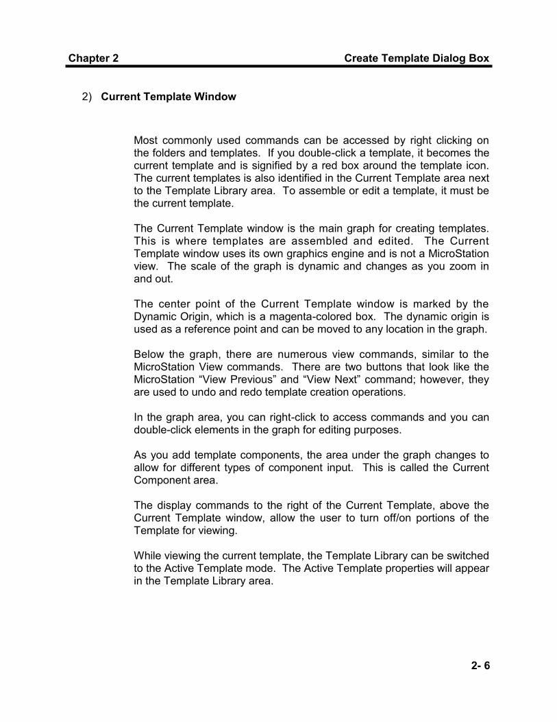
2) Current Template Window
Most commonly used commands can be accessed by right clicking on the folders and templates. If you double-click a template, it becomes the current template and is signified by a red box around the template icon. The current templates is also identified in the Current Template area next to the Template Library area. To assemble or edit a template, it must be the current template. The Current Template window is the main graph for creating templates. This is where templates are assembled and edited. The Current Template window uses its own graphics engine and is not a MicroStation view. The scale of the graph is dynamic and changes as you zoom in and out. The center point of the Current Template window is marked by the Dynamic Origin, which is a magenta-colored box. The dynamic origin is used as a reference point and can be moved to any location in the graph. Below the graph, there are numerous view commands, similar to the MicroStation View commands. There are two buttons that look like the MicroStation “View Previous” and “View Next” command; however, they are used to undo and redo template creation operations. In the graph area, you can right-click to access commands and you can double-click elements in the graph for editing purposes. As you add template components, the area under the graph changes to allow for different types of component input. This is called the Current Component area. The display commands to the right of the Current Template, above the Current Template window, allow the user to turn off/on portions of the Template for viewing. While viewing the current template, the Template Library can be switched to the Active Template mode. The Active Template properties will appear in the Template Library area.

InRoads Template Library
2-7

Create Template Dialog Box
2- 8
Chapter 2
3) Template Preview Window
When you highlight a non-current template, the template is displayed in the Preview area, located under the Template Library area. The Preview area is used to assemble templates from their parts or components using drag and drop to the Current Template window graph. The cyan-colored box in the preview represents the insertion point for any drag and drop operation. You can change the point of insertion location by clicking on the preview.
4) Dynamic Settings
The Dynamic Settings dialog box is used for precision input of the template components, and to dynamically assign point names and style when creating components. It is also a compass and can be used for the location of your cursor with respect to the dynamic origin. The dynamic origin can be moved using “Set Dynamic Origin” located at the bottom of the Dynamic Settings dialog box. Below the graph, with the view control icons, is the icon for Dynamic Settings. The Key-in Pull-Down specifies the type of key-in to be performed: XY = Key-in Absolute Coordinates DL = Key-In Delta Coordinates from last point placed HS = Key-In Horizontal Delta Distance and Slope from last point
placed VS = Key-In Vertical Delta Distance and Slope from last point placed OL = Key-In Delta Coordinates from Dynamic Origin OS = Key-In Horizontal Delta Distance and Slope from dynamic origin

InRoads Template Library
2-9

Create Template Dialog Box
2- 10
Chapter 2
6) Template Library Menu Bar
In the Create Template Dialog box, menu commands include: File, Edit, Add, Tools. Many of these commands will be covered in this manual. There are other means of accessing most of these commands, mainly with right-click menus. The Default standard for Affixes is set in the Template “Options” Dialog Box. The standard Suffix for side of roadway is _L and _R. Standard Step Options are also available in this dialog box. Affixes will be automatically added during component placement when components are being used to create templates. To disable Apply Affixes on the fly, use the Dynamic Settings Dialog Box and manually toggle off “Apply Affixes” during placement of a component. The use of Affixes and Steps will be further explained during this course.
5) Point Name List—Template Points
The template point names represent the names of Digital Terrain Model (DTM) features that are generated when the template is used to create a model of the roadway. Template Point Names will be discussed in Chapter 3 of this manual. Point Name List—Use this dialog box to manage entries in the default point name list. Existing Point Names can be modified, predefined styles can be assigned to points, or you can add new Point Names as needed. The Point Name List has been populated with the list of standard point names for templates in the InRoads XM Version. Right Click to Edit, or Double Click, on the Point Name List.
7) Template Library Organizer
Templates can be copied from one Template Library to another with the Tools> Template Library Organizer.

InRoads Template Library
3-1
Point Constraints
3- 2
Chapter 3
Chapter 3
Point Constraints and Components
This chapter will introduce you to Template Point Controls and Components. Point Constraints are used for control of Template Points. Components are closed or open shapes, and are parts of a template. This chapter will introduce you to components, and show you how to use and manipulate Point Constraints on components. You will learn about the Point naming convention.

InRoads Template Library
3-3

Point Constraints
3- 4
Chapter 3
As in past versions of InRoads, template point names represent the names of Digital Terrain Model (DTM) features that are generated when the template is used to create a model of the roadway. This modeling process is now accomplished using the Roadway Designer command (previously called the Roadway Modeler). Templates are created and controlled by Points. Template point names are assigned during the template creation process from the list of standard template point names predefined within the Point Name List. The standard list of points is based on the naming convention for InRoads XM, using the same feature styles from MicroStation levels. Point names replace the transition control name from Template segments. Names of features will be the name of the template points. Point names must be unique within a template. Top points of components create the Finished Grade and are assigned the FG_ prefix designation. Pavement Layers are designated with prefix letters representing pavement courses. Top points within Subbase components are designated with the prefix SB_; bottom points within Subbase components are designated with the prefix SG_. The following list is for clarification: Finished Grade/Top of Top course: FG_FEATURE_SIDE (FG_LFILL_L; FG_PET_L) Top of Binder Course: BN_FEATURE_SIDE (BN_PET_L) Top of Base Course: BS_FEATURE_SIDE (BS_PET_L) Top of Permeable Course: PB_FEATURE_SIDE (PB_PET_L) Top of Subbase Course: SB_FEATURE_SIDE (SB_PET_L) Bottom of Subgrade: SG_FEATURE_SIDE (SG_PET_L, SG_RELB_R) The standard Suffix for side of roadway is _L and _R. These suffixes are added to the Template Points during the template building process and are discussed in Chapter 4. Building templates and roadway corridors uses a process of controlling points, similar to InRoads V8.05 and older used template segments. In InRoads XM, road models are built from points controlled by constraints. Each template is connected longitudinally to the next template drop to form longitudinal breakline features.
1) Template Points—Point Names

InRoads Template Library
3-5

Point Constraints
3- 6
Chapter 3
A Component is a group of template points that make up an open or closed shape. Components are logical parts of a template; therefore, Components are used as “parts” to assemble complete templates. Portions of the template that are separated into components are normally based on tabulation considerations. Components can represent any roadway feature, such as curb, gutter, sidewalk or other miscellaneous detailed portion of a template. Components can also represent pavement and subbase layers, bridge decks, cut and fill conditions, and other logical parts of a template. During the roadway design process, template components will be used to generate a DTM of the top layer of the design. Components that have subgrade points will be added to the DTM as non-triangulated points. Previous DTM challenges, such as designing vertical slopes and undercuts, are simplified using components. This results in only having one DTM that contains all modeled layers of the design. Components are a child of the DTM. Each Component in the Standard Template Library has a logical name, description, and style. Individual component names are used in the creation of pavement layers and sub-surfaces; therefore logical names and styles for the components are required. This practice will help to produce consistent results when these components are used for volume calculations. Components which will be viewed as MicroStation line elements, are assigned Cross Section Line styles (XSL). These include open Finished Grade components such as Cut and Fill Slopes, Pavement Landscape Elevation Breaks and Shoulder Backup components. The most common use of viewing all other components is in cross sections for volumes; therefore, the style of the remainder of template components are cross section component styles (XSC). There are multiple styles for each type of component, this is a list of style types: XSCBASE, Base Pavement Course; XSCBINDER, Binder Pavement Course; XSCCONC, Concrete Courses (Bridge Deck, etc.); XSCMISC, for miscellaneous components (Curb, Sidewalk, etc.); XSCPBASE, Permeable Base Course; XSCSBASE, Subbase Course; XSCTOP, Top Pavement Course; XSCCUC, Subgrade Under-Cut; XSCCUD, for Underdrain/Edgedrain.
2) Template Components
InRoads Template Library
3-7
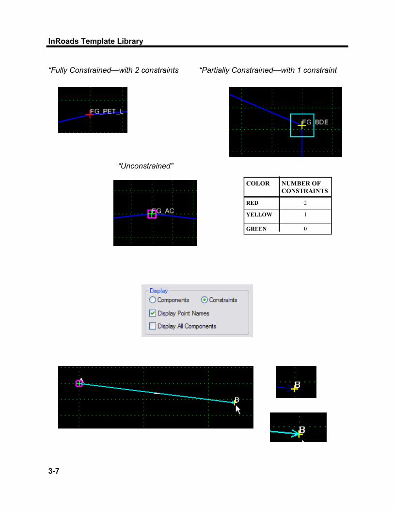
“Fully Constrained—with 2 constraints
“Unconstrained”
“Partially Constrained—with 1 constraint
COLOR NUMBER OF
CONSTRAINTS
RED 2
YELLOW 1
GREEN 0

Point Constraints
3- 8
Chapter 3
Constraints on points manage the behavior of template points. Using point constraints controls the movement of a point in a template. If a point is moved in a template, either by the user when editing a template or by the application of point controls during design processing, all points related to the point being moved will behave in a manner that is predictable. These are basic Point Constraint rules: A template can only have a maximum of 2 constraints on it. When a
point has 2 constraints it is considered “fully constrained.” A point that is fully constrained is represented by a red plus sign.
A point that has only 1 constraint on it is considered “partially
constrained.” This point is shown as a yellow plus sign A point with no constraints, “unconstrained,” is shown as a green plus
sign. Point constraints are determined by a Parent-Child point relationship. When a point is constrained, they are constrained in a two dimensional plane. Constraints can affect only the point’s offset and elevation, the X and Y coordinates in a cross section view. Point constraints are directional. The direction forms the parent-child relation ship between points. If point B is constrained by point A, point A is said to be the parent of point B. When viewing the constraints, the parent point has a blue arrow pointing to the child point. To see constraints in a template, enable the Constraints toggle located in the Display portion of the Create Template dialog box. Types of Constraints include: Horizontal The child point remains at the given horizontal distance from the parent point. Vertical The child point remains at the given vertical distance from the parent point Slope The child point maintains the given slope from the parent point. Slope constraints can, additionally, have rollover values assigned to them.
3) Point Constraints

InRoads Template Library
3-9

Point Constraints
3- 10
Chapter 3
Horizontal Maximum The child point has 2 parent points and remains at the given horizontal distance from the parent point that is farthest to the right (the point with the maximum horizontal or X value). Horizontal Minimum The child point has 2 parent points and remains at the given horizontal distance from the parent point that is farthest to the left (the point with the minimum horizontal or X value). Vertical Maximum The child point has 2 parent points and remains at the given vertical distance from the parent point that is highest (the point with the maximum vertical or Y value). Vertical Minimum The child point has 2 parent points and remains at the given vertical distance from the parent point that is lowest (the point with the minimum vertical or Y value). Vector Offset The child point has 2 parent points and will be projected onto the vector defined by the 2 parents. If the offset is not 0, then the child point maintains a perpendicular offset from the parent vector at the specified offset value. Negative values indicate an offset to the left of the vector defined by the parent points; positive values indicate an offset to the right. Project to Surface This constraint must be used in conjunction with one of the previously defined constraints. The other constraint will define the projection direction. The child point will then be projected to the surface with the name given when the design is processed. If the surface does not exist, or no solution is found, the point will remain where it is placed in the template. Project to Design This constraint is similar to Project to Surface; except, that the point is projected to the design surface of the template. A projection value is given to indicate whether the projection is to be to the left or to the right. Again, the point must also be constrained by one of the previous constraints, excluding the Project to Surface, so that a direction for the projection may be determined. Again, if no solution is found, the point will remain where it is placed in the template. Angle Distance This is one constraint with two parents. Combinations of constraints can be used, and a child may have 2 parents.
InRoads Template Library
3-11
Point Constraints
3- 12
Chapter 3
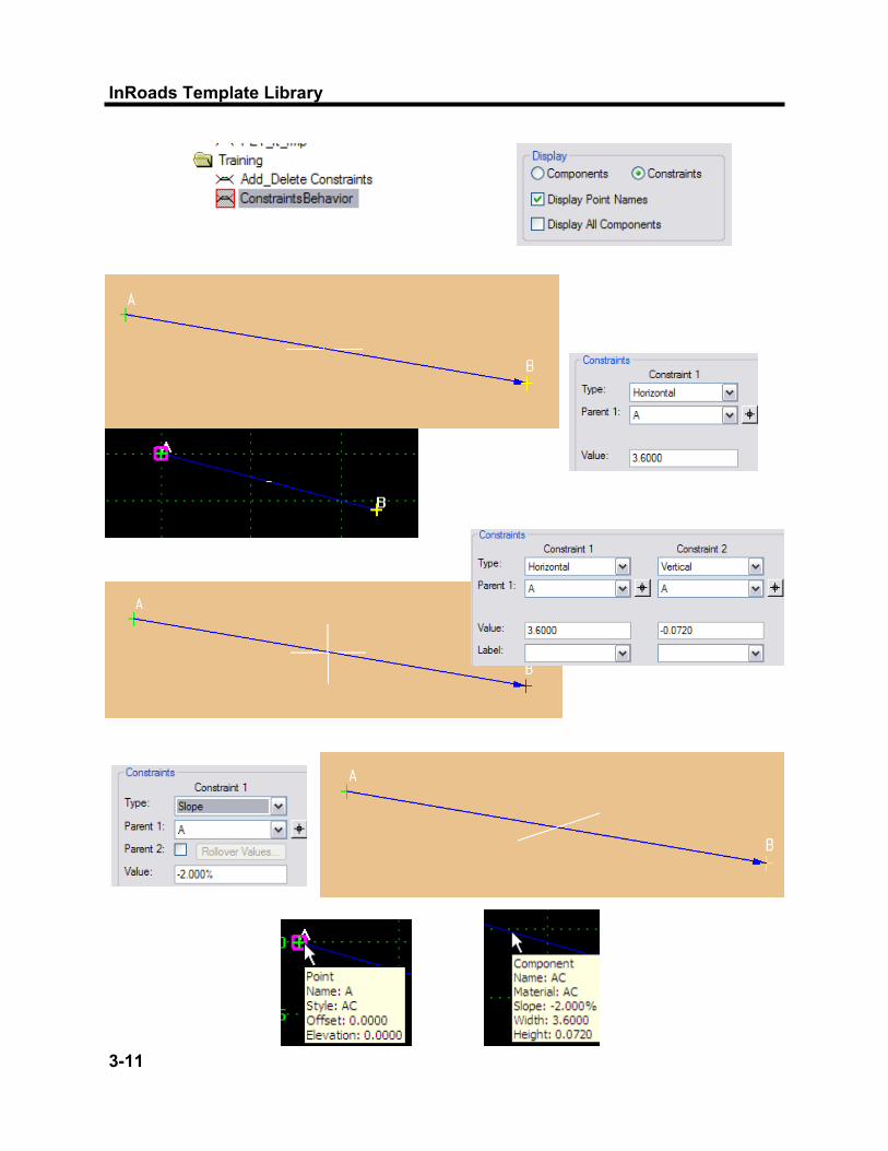
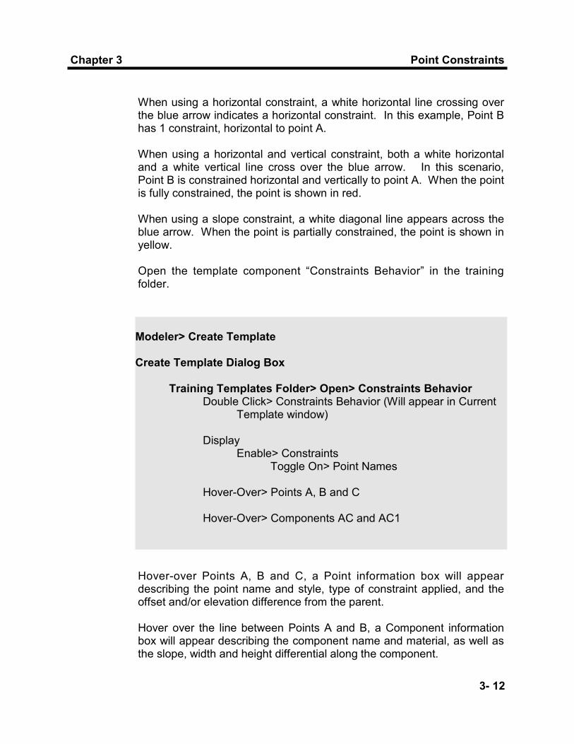
When using a horizontal constraint, a white horizontal line crossing over the blue arrow indicates a horizontal constraint. In this example, Point B has 1 constraint, horizontal to point A. When using a horizontal and vertical constraint, both a white horizontal and a white vertical line cross over the blue arrow. In this scenario, Point B is constrained horizontal and vertically to point A. When the point is fully constrained, the point is shown in red. When using a slope constraint, a white diagonal line appears across the blue arrow. When the point is partially constrained, the point is shown in yellow. Open the template component “Constraints Behavior” in the training folder.
Modeler> Create Template Create Template Dialog Box Training Templates Folder> Open> Constraints Behavior Double Click> Constraints Behavior (Will appear in Current Template window) Display Enable> Constraints Toggle On> Point Names Hover-Over> Points A, B and C Hover-Over> Components AC and AC1
Hover-over Points A, B and C, a Point information box will appear describing the point name and style, type of constraint applied, and the offset and/or elevation difference from the parent. Hover over the line between Points A and B, a Component information box will appear describing the component name and material, as well as the slope, width and height differential along the component.

InRoads Template Library
3-13
Point Property Dialog Box: Double Click on Point—Or Right Click> Edit Point

Point Constraints
3- 14
Chapter 3
With the vertical constraint removed from Point B, the color of the Point changed from red to yellow. The point is now able to be moved. With the horizontal constraint remaining, the distance between Point A and Point B constantly remains the same.
Point A is the parent of Point B—Point B is the child of Point A Point B is horizontally and vertically constrained to Point A Point B is the parent of Point C—Point C is the child of Point B Point C is horizontally and vertically constrained to Point B
Create Template Dialog Box Constraints Behavior Template Right Click> Point A Select> Move Point Observe> Behavior of Points Right Click> Point B Select> Move Point is Unavailable Double Click> Point B Point Properties Dialog Box Constraint 2 Select Vertical> Change To> None Apply Close
4) Manipulating Points and Point Constraints
Create Template Dialog Box Constraints Behavior Template Right Click> Point B Select> Move Point
InRoads Template Library
3-15
Point Constraints
3- 16
Chapter 3
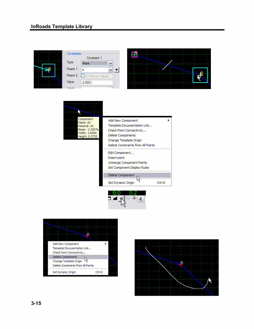
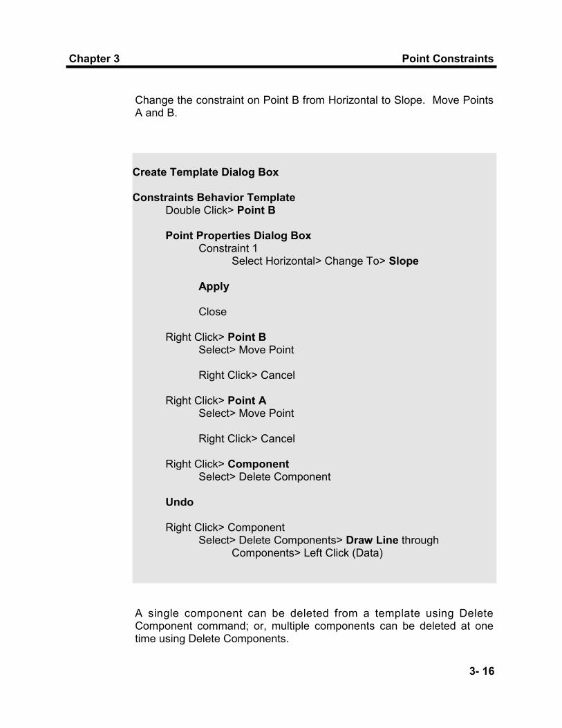
Change the constraint on Point B from Horizontal to Slope. Move Points A and B.
Create Template Dialog Box Constraints Behavior Template Double Click> Point B Point Properties Dialog Box Constraint 1 Select Horizontal> Change To> Slope Apply Close Right Click> Point B Select> Move Point Right Click> Cancel Right Click> Point A Select> Move Point Right Click> Cancel Right Click> Component Select> Delete Component Undo Right Click> Component Select> Delete Components> Draw Line through Components> Left Click (Data)
A single component can be deleted from a template using Delete Component command; or, multiple components can be deleted at one time using Delete Components.
InRoads Template Library
3-17
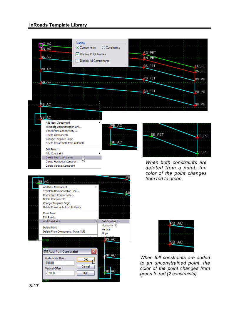
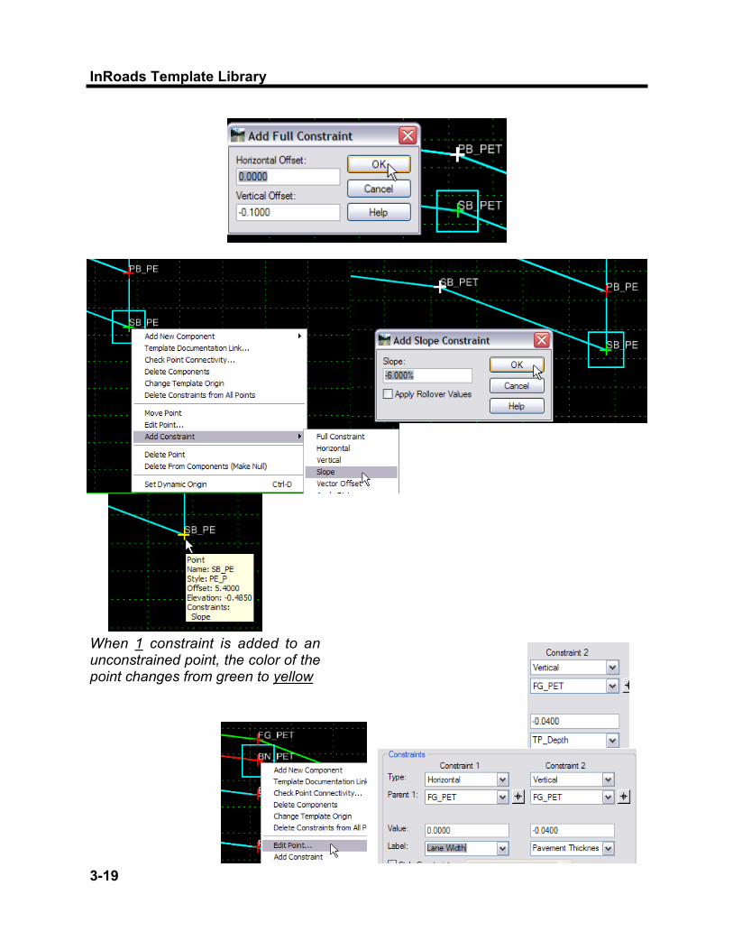
When both constraints are deleted from a point, the color of the point changes from red to green.
When full constraints are added to an unconstrained point, the color of the point changes from green to red (2 constraints)

Point Constraints
3- 18
Chapter 3
In addition to editing the template point constraints using the Point Properties Dialog box, a right-click on any point can access Add Constraint or Delete Constraints. Delete Constraints removes all constraints from a point. Add Constraint allows you to pick the type of constraint you want to add to the point. Full Constraints adds both horizontal and vertical constraints to a point. Setting the appropriate constraints on points is important to achieve the desired results when pavement layers, superelevation and point transitions are introduced to the design process. Use the Point Properties to adjust point constraints after initial point placement, if necessary.
Create Template Dialog Box Add_Delete Constraints Template Right Click> Point SB_AC (Component PB) Select> Delete Both Constraints Right Click> Point SB_PET Select> Delete Both Constraints Right Click> Point SB_PE Select> Delete Both Constraints Right Click> Point SB_AC Select> Add Constraint> Full Constraint Data Select> Point PB_AC (Component BS) Add Full Constraint Dialog Box Horizontal Offset> 0.0000 Vertical Offset> -0.1000 OK
5) Deleting and Adding Point Constraints
InRoads Template Library
3-19
When 1 constraint is added to an unconstrained point, the color of the point changes from green to yellow
Point Constraints
3- 20
Chapter 3
Constraints can be labeled so that during the design process the value of labeled constraints may be changed. For example, the template may have a constraint label called “Pavement Thickness” that controls the depth of the pavement layer. The pavement thickness can be changed in the Roadway Designer so that one template can be used for different pavement layer depths, without having to edit the template. Once a Point Label is created in the Template Library, this label is available for use with other points as a pull-down choice. To create a new Label, type in the desired name. More will be discussed on this topic using Parametric Constraints in the InRoads XM Roadway Designer course.
Add_Delete Constraints Template Right Click> Point SB_PET Select> Add Constraint> Full Constraint Data Select> Point PB_PET (Component BS) Add Full Constraint Dialog Box Horizontal Offset> 0.0000 Vertical Offset> -0.1000 OK Add_Delete Constraints Template Right Click> Point SB_PE (Component PB) Select> Add Constraint> Constraint> Slope Data Select> Point SB_PET (Component PB) Add Slope Constraint Dialog Box Slope> -6.00% OK
6) Point Labels

InRoads Template Library
4-1
Component Creation
4- 2
Chapter 4
Chapter 4
Creating Components
This chapter will introduce you to component creation and editing. Shapes, called components, can be created in the template library and used to build templates. This chapter will teach you how to create Templates from Components, and how to edit a template by Editing Template Point Controls.

InRoads Template Library
4-3
Component Creation
4- 4
Chapter 4
1) Component Slopes and Distances
When components are created with precision input, the parent-child relationship determines the sign of the distance. The parent is always the first point placed. The child placed to the right (X) of the parent is positive distance; the parent has a lower X value than the child. The child placed to the left (X) of the parent is negative distance; parent has a higher X value than the child. The sign of the component slope is based on the mathematical/algebraic slope.
2) Component Names
The components are named for the point and layer they represent. Components are designated with the same prefix as the points on the component, followed by the segment name if applicable. The pavement layers are designated with the prefix, followed by the feature (if applicable). Subbase components are designated with the prefix SB, for Top of Subbase, or SG, for Bottom of Subbase/Subgrade. The following list is for pavement components: Top Course: TP_FEATURE (TP_PET) Binder Course: BN_FEATURE (BN_PET) Base Course: BS_FEATURE (BS_PET) Permeable Course: PB_FEATURE (PB_PET) Subbase/Subgrade Course: SB (Top)/SG(Bottom)_FEATURE (SB_PET) When Pavement components are merged together, the name should be changed as appropriate for the entire component. If the top course is merged and represented by one component, the component would be named “TP.” Miscellaneous Components, such as Curb Details, are named by the Feature Style, followed by the Type. For example, a Type M150 Concrete Curb Component will be named RC_M150. Component Styles are discussed on page 3-6 of this manual.

InRoads Template Library
4-5

Component Creation
4- 6
Chapter 4
A Component is an open or closed shape defined by a set of points. Each component, open or closed, can represent a different material or area. Components can be children or parents of other components, also. Examples include Daylight Subbase and Subbase Box Out Components; they are children of Cut and Fill Slopes in End Conditions. Five types of components can be created in InRoads: Simple Constrained Unconstrained Null Point End Condition A simple component typically represents a section of pavement or sidewalk. It is a closed parallelogram that is defined by slope, thickness and width. The top points are constrained by horizontal and slope constraints. The lower points are constrained to the points directly above them with horizontal and vertical constraints. Create a New Template, TP_R, which will be Top Course Pavement on the Right Side of Roadway. Add a good Description.
3) Create Simple Component
Create Template Dialog Box Training Folder> Right Click> New> Template Name> TP_R Double Click> TP_R (Appears in Current Template window) Description> TOP COURSE PAVEMENT
Create a simple component called TP_PET_R. Begin with the Point Name FG_AC. As Template Components are added, the Current Component area (the area under the graph) changes to allow for different types of component input.
InRoads Template Library
4-7
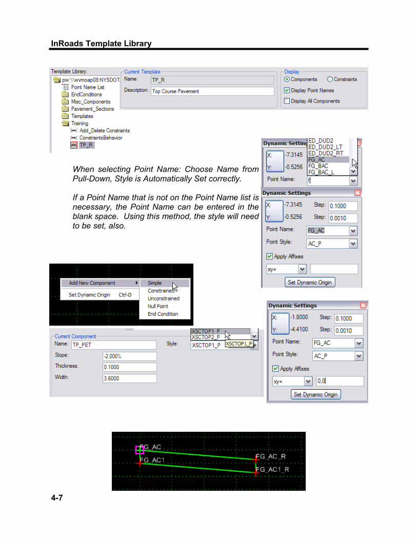
When selecting Point Name: Choose Name from Pull-Down, Style is Automatically Set correctly. If a Point Name that is not on the Point Name list is necessary, the Point Name can be entered in the blank space. Using this method, the style will need to be set, also.
Component Creation
4- 8
Chapter 4
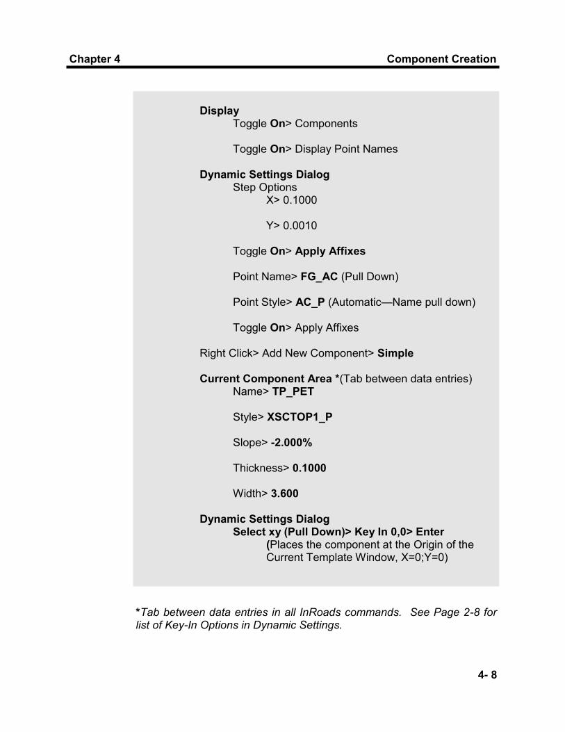
Display Toggle On> Components Toggle On> Display Point Names Dynamic Settings Dialog Step Options X> 0.1000 Y> 0.0010 Toggle On> Apply Affixes Point Name> FG_AC (Pull Down) Point Style> AC_P (Automatic—Name pull down) Toggle On> Apply Affixes Right Click> Add New Component> Simple Current Component Area *(Tab between data entries) Name> TP_PET Style> XSCTOP1_P Slope> -2.000% Thickness> 0.1000 Width> 3.600 Dynamic Settings Dialog Select xy (Pull Down)> Key In 0,0> Enter (Places the component at the Origin of the Current Template Window, X=0;Y=0)
*Tab between data entries in all InRoads commands. See Page 2-8 for list of Key-In Options in Dynamic Settings.
InRoads Template Library
4-9

Component Creation
4- 10
Chapter 4
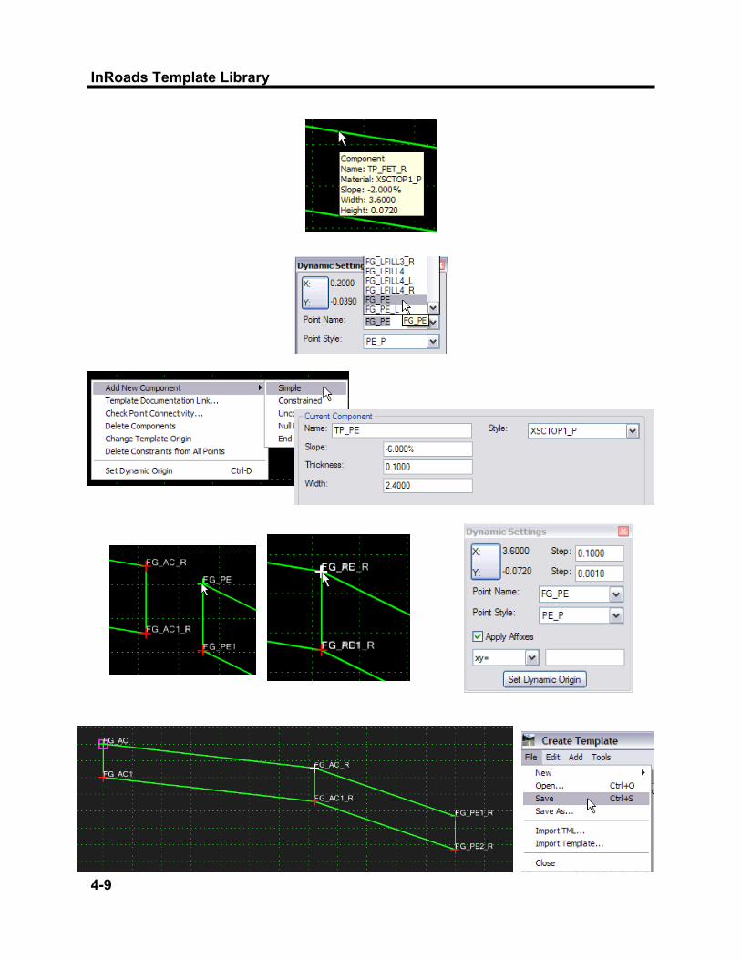
The component’s name is TP_PET_R; because “Apply Affixes” was toggled on, the prefix _R was added to the component. Change the Point Name for the second simple component to FG_PE. Set up the Current Component area as you proceed through component creation.
Training Folder> TP_R Dynamic Settings Dialog Point Name> FG_PE (Pull Down) Point Style> PE_P Right Click> Add New Component> Simple Current Component Area Name> TP_PE Style> XSCTOP1_P Slope> -6.00% Thickness> 0.100 Width> 2.4 Place Point FG_PE on Point FG_AC_R (Point will turn white for exact placement on point> Data Dynamic Settings Dialog When Placing the component at the FG_AC_R Point, X:/Y: watch readout X = 3.6; Y = -0.072 (Point could be placed with Key In)
Save the Template Library; the Template Library can be saved in the Create Template dialog box.

InRoads Template Library
4-11

Component Creation
4- 12
Chapter 4
Templates are used by the Roadway Designer to create surfaces of the proposed roadway. Component points, which will create Surface Features, will need to follow the correct naming convention. Detailed information on the naming convention for template points is in Chapter 3 of this manual, in the section entitled Template Points—Point Names. The surface created by the top points will not have a layer prefix designation. The point of origin is the centerline of the roadway from the horizontal and vertical alignments and is called “FG_AC.” The point below the FG_AC will be on the bottom of the Top Course, or the top of the Binder Course; therefore the name of the point will be BN_AC. Edit all the Template Points, selecting the correct names from the Point Name List.
Create Template Dialog Box> Training Folder> TP_R Right Click Point FG_AC1> Edit Point (Or Double Click) Point Properties Dialog Box Name> FG_AC1> BN_AC Surface Feature Style> AC_P Apply Next Name> FG_AC_R> FG_PET_R (Pull-Down) Surface Feature Style> PET_P (Automatic using Pull-Down Point Name) Apply Next Name> FG_AC1_R> BN_PET_R Apply
4) Edit Template Point Names
InRoads Template Library
4-13
Component Creation
4- 14
Chapter 4
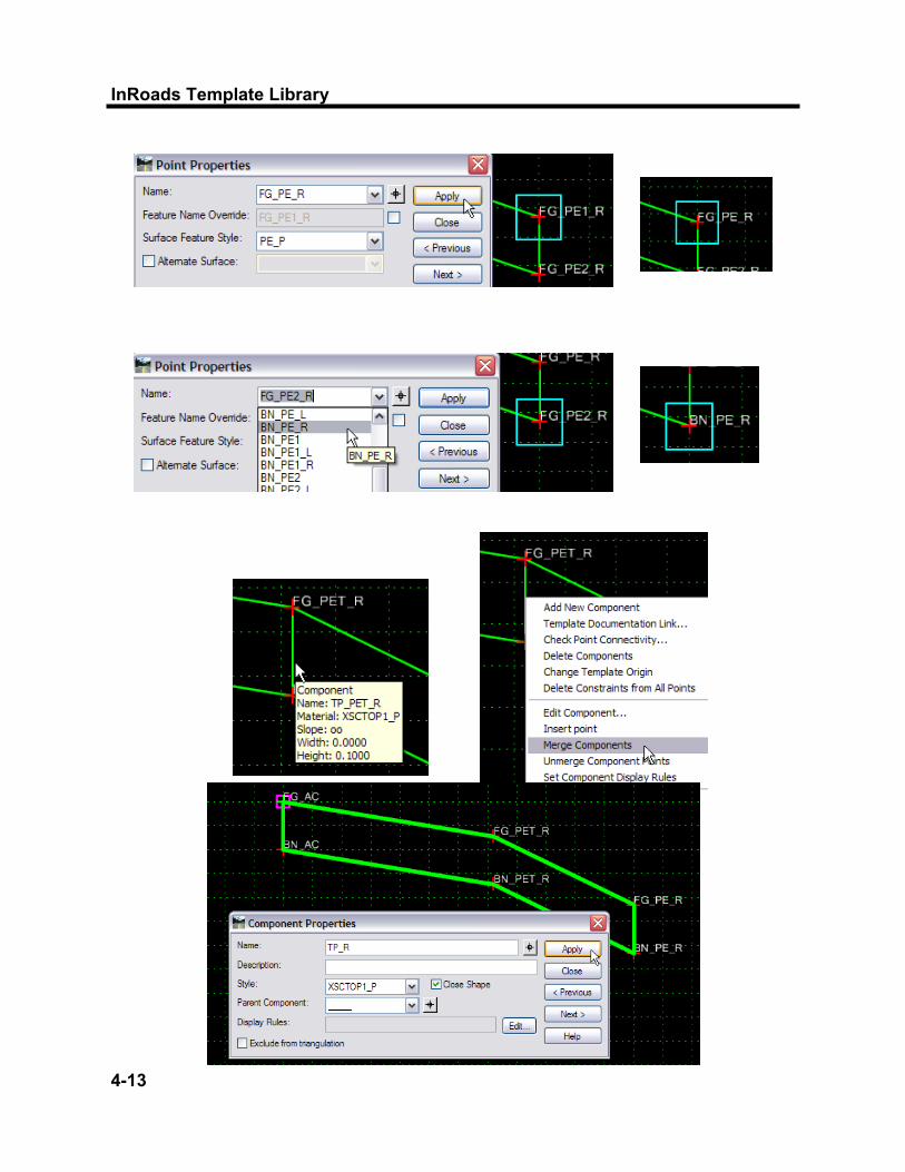
Next Name> FG_PE1_R> FG_PE_R Surface Feature Style> PE_P Apply Next Name> FG_PE2_R> BN_PE_R Apply Close
Save the Template Library.
Two or more separate components of like materials, such as the same course of pavement, can be merged together to create a single component. When components are merged together, the vertical line which divides them is removed. To merge components together, point to the dividing line and right-click to Merge Components command.
5) Merge Components
Training Folder> TP_R TP_R (Appears in Current Template window) Right Click> Where Pavement Edge of Travelway meets Pavement Edge Component> Merge Components
Once components are merged together, they then need to be renamed. The component no longer represents just the right pavement edge of travelway or right pavement edge, but a combination of both. Double Click on the component and change the name to TP_R.

InRoads Template Library
4-15
Component Creation
4- 16
Chapter 4
Constrained components are created with horizontal and vertical constraints automatically applied. Examples of constrained Components include median barrier, curb and gutter sections, retaining walls and complex pavement sections. Unconstrained components are created with no constraints; then, manually, constraints can be added after the component is created. Both open and closed shapes can be created; this option is available by right-clicking on the Current Template Window while components are being created. During component creation, the Dynamic Settings dialog is used to define point names and styles. The Dynamic Settings dialog can be used to enter the precise location for the points. Create a constrained template using the Dynamic Settings Dialog precision input. Create a Type D Stone and Granite Curb as per Detail on page 4-15. Toggle Off “Apply Affixes.”
6) Create Constrained and Unconstrained Components
Create Template Dialog Box> Training Folder> Right Click> New> Template Name> RC_D Double Click> RC_D (Appears in Current Template window) Display Toggle On> Components Toggle On> Display Point Names Dynamic Settings Dialog box Point Name> FG_PE (Pull Down) Point Style> PE_P (Automatic—Name pull down) Toggle Off> Apply Affixes Right Click> Add New Component> Constrained

InRoads Template Library
4-17
Use View Command as necessary /Use Mouse Wheel to change view

Component Creation
4- 18
Chapter 4
Current Component Area Name> RC_D Style> XSCMISC1_P Dynamic Settings Dialog box Name> FG_PE Select xy (Pull Down)> Key In 0,0> Enter Name> FG_RCT Select xy> Key In 0.038,0.150> Enter Name> FG_RCB Select dl (Pull Down)> Key In 0.125,0> Enter Name> RCB Select dl> Key In 0,-0.400> Enter Name> RC Select dl> Key In –.163 ,0> Enter (.125 + .038=.163) Right Click or “Enter”> Finish
At any time during the process of creating a component, the command “Undo Last” is available by right-clicking in the Current Template Window. Also, the escape key, “ESC,” allows you to go back during the precision input process. Save the Template Library. A Review of the Point Properties shows that the points were created with horizontal and vertical constraints, by using constrained component.

InRoads Template Library
5 - 1

Template Creation
5 - 2
Chapter 5
Chapter 5
Creating Templates
This chapter will introduce you to creating and editing templates. This chapter will teach you how to build complete Templates from Components, and how to edit a template by Editing Template Point Controls. In this chapter, you will learn how to place and use End Conditions with templates.

InRoads Template Library
5 - 3
Template Creation
5 - 4
Chapter 5
Although there are already several standard templates provided in the Template Library which can be edited, there may be a need to create a template with a different combination of components. Create a new template in the Training Folder called 2lane_Rural.
1) Create New Template
Modeler> Create Template Create Template Dialog Box Training Folder> Right Click> New> Template Name> 2lane_Rural Double Click> 2lane_Rural> Add Description (Appears in Current Template window) Description> Edge Drain, Ditches & Cut & Fill Decision
Build the new template using pavement, miscellaneous and end condition components. To assemble a Template, simply drag and drop the components to the Current Template window. A single-click on a component will display the component in the Preview Window. A Right-Click in the Current Window while dragging a component for placement will allow you to return to the Dynamic Settings Dialog Box. When connecting two components, the connecting point will change to a white colored plus sign prior to placing the component. This indicates that the points coincide. Any coincident component points will use the point names of the previously placed component. Template point names can be edited anytime during the creation process. Affixes can be automatically added during component placement when components are being used to create templates; they can be changed on the fly in the Dynamic Settings Dialog. Toggle On “Apply Affixes.” The standard Suffix for side of roadway is _L and _R. Steps options are set up in “Template Options” to assist with the Dynamic Settings, locating the point of origin, etc.
InRoads Template Library
5 - 5
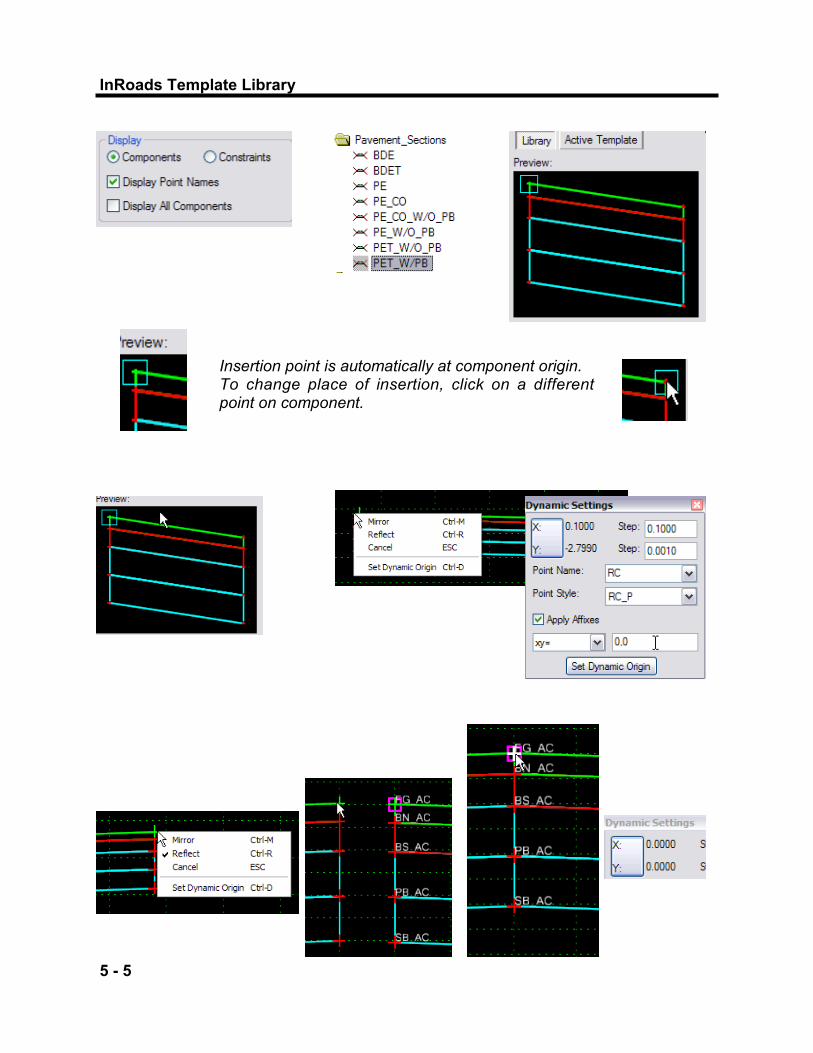
Insertion point is automatically at component origin. To change place of insertion, click on a different point on component.

Template Creation
5 - 6
Chapter 5
Create Template Dialog Box> Training Folder> 2lane_Rural Display Enable> Components Toggle On> Display Point Names Open> Dynamic Settings Dialog Toggle On> Apply Affixes Pavement_Sections Folder Highlight> PET_W/PB Appears in Preview window) Drag and Drop Component Drag> PET_W/PB, From Black Area of Preview window> Right Click While Dragging to Origin X=0; Y=0 (Leave “Data” Button Depressed)> Go to Dynamic Settings Dialog Box Dynamic Settings Select xy (Pull Down)> Key In 0,0> Enter> Drop 2lane_Rural as Current Template Pavement_Sections Folder Highlight> PET_W/PB Drag and Drop Component Drag> PET_W/PB Right Click> Reflect to place Left Side Drop> PET_W/PB> at FG_AC; Point will Highlight in White; (Dynamic Settings Dialog Box Readout at Origin: X=0; Y=0)
Watch the Dynamic Settings for correct readouts as you place points. Adjust Step Options as necessary.

InRoads Template Library
5 - 7
Use window view commands to change views within the Current Template window. Use Mouse Wheel to change views; Mouse Wheel + Ctrl & Mouse Wheel + Shift.
Use “UNDO” in the window view commands area to undo last command.
Mirror—Mirrors the component and adds on both sides of the template; the insertion point is in the direction component is created. Reflect—Adds a mirror image component on the opposite side, only Mirror and Reflect—Same as mirror, but insertion point is on opposite side.

Template Creation
5 - 8
Chapter 5
Pavement_Sections Folder Highlight > PE Drag and Drop Component Drag> PE Right Click> Reflect and Mirror> Drop at FG_PET_L (OR) Right Click> Mirror ONLY> Drop at FG_PET_R Misc_Components Folder Highlight> SB_PET Drag and Drop Component Drag> SB_PET Right Click> Mirror> Drop at SB_AC Misc_Components Folder Highlight > SB_PE Drag and Drop Component Drag> SB_PE Right Click> Mirror> Drop at SB_PET_R
When dragging Components from the Preview Window, using the black area in the Window leaves the insertion point at the default location. Save the Template Library.

InRoads Template Library
5 - 9

Template Creation
5 - 10
Chapter 5
2) Check Point Connectivity
Exact placement of components to the origin and to each other are required to eliminate extra points; misplaced points that go un-noticed can cause problems in the way the surface is created from the template. Use the Check Point Connectivity command to check points on components. Use the default tolerance of 0.005. Points not within that tolerance, will display with a “Delete Point” Dialog box on the screen, giving the user the option to delete the extra point. Do not delete the necessary points. Use the “Escape” key to move to the next conflict, and finally to close the command.
When the components came together at the same point, those points automatically merge together and the first point that was created in the template remains. The point is now shared by both components. For instance, the Subbase layer merged to the bottom of the Permeable Base layer and the Points at the pavement edge of travelway, SB_PET, automatically merged together. If points do not merge automatically, right-click and use the merge points command. The user must choose which point should be deleted. “Unmerge Component Points nullifies the automatic merge of component points merged together during creation of the template. The component that was sharing its points with another component, gets a copy of that point. All constraints between these shared points (and other points in the template) are removed.
InRoads Template Library
5 - 11

Template Creation
5 - 12
Chapter 5
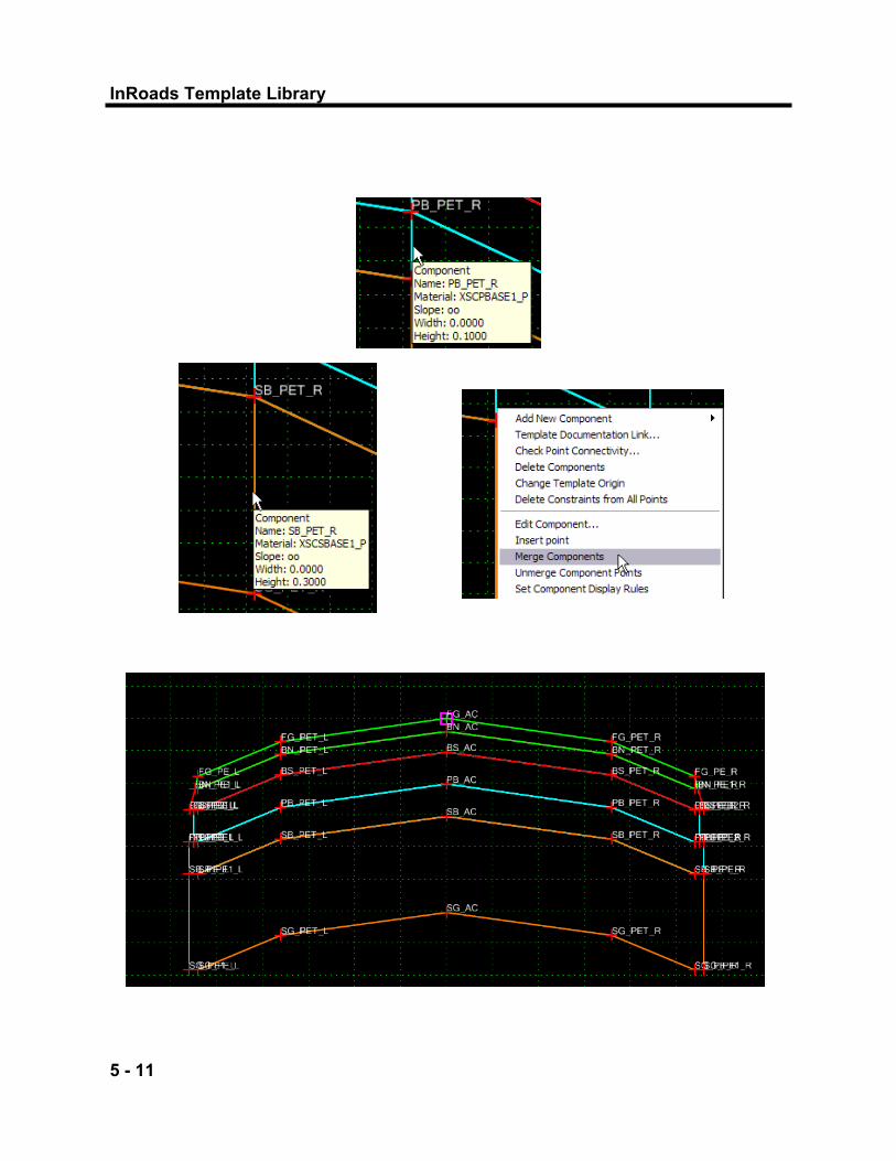
3) Merge Components
Create Template Dialog Box Training Folder> 2lane_Rural 2lane_Rural (Appears in Current Template window) Right Click> Vertical Line where (Pavement Travelway) PET component meet (Pavement Edge) PE Components> Merge Components Do this for all courses; Top Course, Binder Course, Base Course, Permeable Base Course and Subbase Course Right Click> Vertical Line where (Pavement Travelway) PET components meet> Merge Components Do this for all courses; Top Course, Binder Course, Base Course, Permeable Base Course and Subbase Course
Merge all the component pavement layers of the same composition. When this step is complete, there will be only one component for each pavement and subbase layer When combining two components of a pavement section together, two separate components are produced with a vertical segment dividing them. To remove the vertical segment, hold the cursor over the vertical segment and right-click. Then select Merge Components.
If you receive an error message concerning shared points when using the “Merge Component” command, un-merged points exist between the components.

InRoads Template Library
5 - 13
Template Creation
5 - 14
Chapter 5
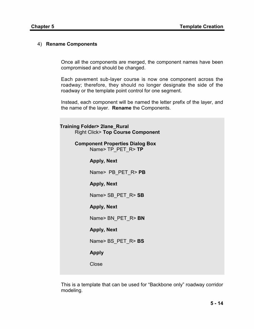
Once all the components are merged, the component names have been compromised and should be changed. Each pavement sub-layer course is now one component across the roadway; therefore, they should no longer designate the side of the roadway or the template point control for one segment. Instead, each component will be named the letter prefix of the layer, and the name of the layer. Rename the Components.
4) Rename Components
Training Folder> 2lane_Rural Right Click> Top Course Component Component Properties Dialog Box Name> TP_PET_R> TP Apply, Next Name> PB_PET_R> PB Apply, Next Name> SB_PET_R> SB Apply, Next Name> BN_PET_R> BN Apply, Next Name> BS_PET_R> BS Apply Close
This is a template that can be used for “Backbone only” roadway corridor modeling.

InRoads Template Library
5 - 15

Template Creation
5 - 16
Chapter 5
Any changes necessary to a template can be made through Point Properties. Access the Point Properties dialog box by right-click to Edit Point, or by double-clicking any point. Change the width of the roadway from 3.6 m to 3.3 m, and the width of the shoulders from 1.8 m to 2.4 m. Change the Horizontal Constraints Value on the FG_PET_R, FG_PET_L, FG_PE_R and FG_PE_L points on the template surface.
5) Edit Components
Training Folder> 2lane_Rural 2lane_Rural (Appears in Current Template window) Right Click> FG_PET_R> Edit Point Point Properties Dialog Box Constraints Constraint 2 (Whichever constraint is horizontal) Type> Horizontal Constraint Parent> FG_AC Value> 3.6000> 3.3000 Apply Locate> FG_PE_R Constraints Constraint 1 (Whichever constraint is horizontal) Type> Horizontal Constraint Parent> FG_PET_R Value> 1.8> 2.4 Apply Locate> FG_PET_L Constraints

InRoads Template Library
5 - 17

Template Creation
5 - 18
Chapter 5
Constraint 1 (Whichever constraint is horizontal) Type> Horizontal Constraint Parent> FG_AC Value> -3.6> -3.3 Apply Locate> FG_PE_L Constraints Constraint 1 (Whichever constraint is horizontal) Type> Horizontal Constraint Parent> FG_PET_L Value> -1.8> -2.4 Apply Close
The Edge of Travelway points on sub-layers are constrained horizontally and vertically to the top surface Edge of Travelway points. The same is true of the left and right Edge of Pavement points. When the top surface points are changed, the width of all the sub-layers automatically changes to the new width of the point to which they are constrained. To view the template points constraints, change the Display View to Constraints.

InRoads Template Library
6 - 1

End Conditions
6 - 2
Chapter 6
Chapter 6
End Conditions
This chapter will teach you how End Conditions work, how to test them, and how to check their operation in a template. In this chapter, you will learn how to place and use End Conditions with templates.

InRoads Template Library
6 - 3

End Conditions
6 - 4
Chapter 6
End Conditions—Cut and Fill slopes which combine and replace the template cuts and fills and decision tables, the “Catch Point” choices of Roadway Library. The End Conditions components that are supplied in the Standard Template Library include the following: LELB—Variable Cut and Fill Slopes; No subgrade or edgedrain
attached (In Fill Area—Decision on which fill slope will be applied; In Cut Area—Decision on which cut slope will be applied)
LELB_DD_SG_DAYorBOX—Variable Fill Slopes, Ditch with Variable
Cut Slopes. Use without Permeable Base Course. Fill Area—Decision on which fill slope will be applied. Subgrade
Daylight attached to whichever slope is decided upon in Fill Area, once the depth allows for Daylighting condition. Box-Out Subgrade and Edge Drain attached to fill slope to minimal to allow for Daylighting.
Cut Area—Create ditch and decide which cut slope will be applied. LELB_ED—Variable Cut and Fill Slopes; Use with Permeable Base
Course. Fill Area—Decision on which fill slope will be applied. Edgedrain
is used for all fill conditions. Cut Area—Decide which cut slope will be applied. Edgedrain is
used for all cut conditions LELB_ED_SG_BOXOUT—Variable Cut and Fill Slopes; Edgedrain &
Subgrade Box-Out attached to all cut and fill slopes (In Fill Area—Decision on which fill slope will be applied; In Cut Area—Decide which cut slope will be applied). Use without Permeable Base Course.
LELB_ED_DD—Variable Fill Slopes, Ditch with Variable Cut Slopes;
Use with Permeable Base Course. Fill Area—Decision on which fill slope will be applied. Edgedrain
is used for all fill conditions. Cut Area—Create ditch and decide which cut slope will be applied. Edgedrain is used for all cut conditions.
1) End Conditions Provided in Standard Template Library
InRoads Template Library
6 - 5

End Conditions
6 - 6
Chapter 6
LELB_ED_OUTLET—Variable Cut and Fill Slopes; Use with Perm Base Course at Single Station to Outlet Edge Drain.
Fill Area—Decision on which fill slope will be applied. Edgedrain outlet to slope is applied.
Cut Area—Same as LELB_ED LELB_ED_SG_DAYorBOX—Variable Cut and Fill Slopes; Subgrade
Daylight attached to fill slope in fill areas; Subgrade Box-Out attached to cut slope in cut area (In Fill Area—Decision on which fill slope will be applied; In Cut Area—Decide which cut slope will be applied). Use without Permeable Base Course.
Fill Area—Decision on which fill slope will be applied. Subgrade Daylight attached to whichever slope is decided upon in Fill Area, once the depth allows for Daylighting condition. Box-Out Subgrade attached to fill slope too minimal to allow for Daylight.
Cut Area—Decide which cut slope will be applied; Box-Out Subgrade attached to all cut slopes.
Edgedrain is used for both Box-Out and Daylight Conditions
LELB_LWR—Retaining Wall End condition Slope—Cut and Fill Slope set at Eight Degree Batter LELB_LWR_SBRWS—Segmental Block Retaining Wall System Slope—Cut and Fill Slope set at Eight Degree Batter; Blocks are
attached to Cut and Fill Slope to create Block Rows. Display Rules define creation of block rows.
LELB_SG_DAYorBOX_ED—Variable Cut and Fill Slopes; Subgrade Daylight attached to fill slope in fill areas; Subgrade Box-Out attached to cut slope in cut area (In Fill Area—Decision on which fill slope will be applied; In Cut Area—Decide which cut slope will be applied). Use without Permeable Base Course.
Fill Area—Decision on which fill slope will be applied. Subgrade Daylight attached to whichever slope is decided upon in Fill Area, once the depth allows for Daylighting condition. Edgedrain and Box-Out SG only attached to fill slope which does not Daylight.
Cut Area—Decide which cut slope will be applied. Edgedrain and Box-Out Subgrade attached to all cut slopes.

InRoads Template Library
6 - 7

End Conditions
6 - 8
Chapter 6
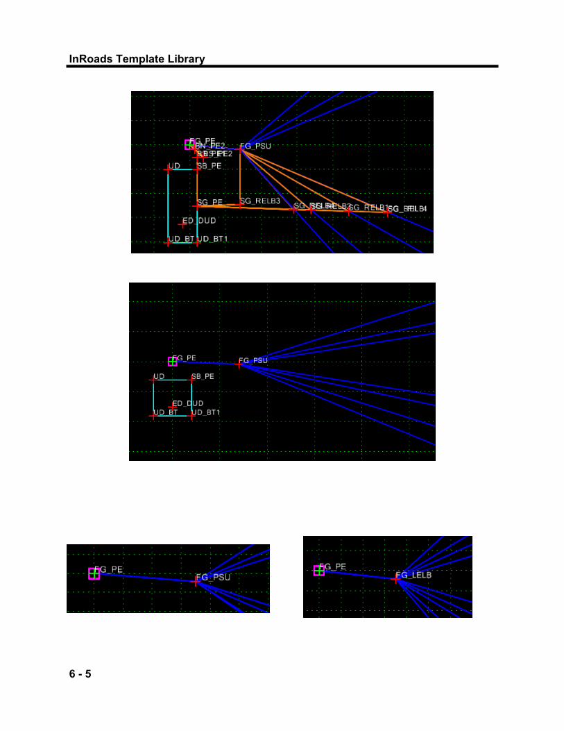
End Conditions components make decisions on cut and fill slopes, and can be added to and used with templates. In each End Condition, individual Cut and Fill Slopes were created as individual components. The Cut/Fill Points use slope and horizontal constraints to the FG_PSU, the Finished Grade pavement shoulder unpaved (shoulder backup) point; or the FG_LELB, landscape elevation break point. The Finished Grade Pavement Edge, FG_PE, is the component’s point of origin. The name of each component begins with the style (level) and a logical description was given to each component. The components, in Component Properties, are set up to find the Active Surface as the target. They are “prioritized” in the order in which they will make a “decision.” The priority sequence that is set up in the standard end conditions at each component that begins at the same point. Decide which end condition component is most desirable for the project. This component, the most desirable end condition component, would be assigned the lowest priority number, in this case a priority of 1. The last condition to be tested, when other tests have failed, is given the highest priority number. Priorities can be re-sequenced, depending on ROW limitations and other design requirements of the project. The horizontal distance can be changed in each of the cut and fill slopes, as necessary, to change the distance in which a particular slope travels to attempt to find the target. Each Cut and Fill slope percentage is determined by the value of the Slope Constraint. The Horizontal Constraint value determines the distance a particular slope will travel to arrive at the target (active surface). If the first slope cannot meet the target within that distance, an attempt is made at placing the next slope in order of priority. The final, infinite, Cut and Fill Slopes are created with Project to Surface Constraints along with the Slope Constraints. If previous slopes failed to find a target, this final cut/fill slope will be “infinite” and will project to the surface that is applied in the “Value” of the Project to Surface constraint. Changes can be performed in either the Component Properties or Point Properties Dialog Boxes.
2) End Conditions’ Settings and Properties

InRoads Template Library
6 - 9

End Conditions
6 - 10
Chapter 6
Other End Condition Component settings that have to be considered in order to obtain the desired results are the following: Check for Interception—when this toggle is checked on, the line
segment will search for the specified target. When this toggle is checked off, the line segment will be created at its full width regardless of whether it intersects the target, provided one of the seg-ments connected to this segment successfully intersects the target.
Place Point at Intersection—when this toggle is checked on, a point
will be placed at the location of the interception. End Condition is Infinite—when this toggle is checked on, the line
segment will automatically be extended to intercept the target. When the toggle is checked off, the line segment will only extend to its maximum constraint to meet its target. This setting applies only to the last line segment in an end condition.
Do Not Construct—when this toggle is checked on, the end point of
the line segment will be used as a reference point to find a subsequent point. The point will be solved for, like any other end condition point, but that point will be skipped when drawing the final component segments. This is normally checked off, and is used only for more complex conditions decisions.
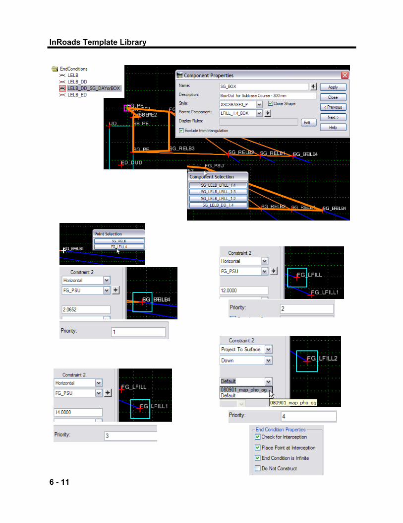
In the End Conditions which feature Subbase Daylighting/Box-Out conditions, Subbase Components and Subgrade Conditions are children of Cut and Fill Slope Components. For Instance, the Subgrade Box-Out component, SG_BOX is a child of LFILL_1:4_BOX component in the LELB_DD_SG_DAYorBOX End Condition. Each Subgrade Daylight Component is a child of a different fill slope, or ditch section. In areas where multiple components are in the same location, Right-Click on component which will bring up the Component Selection Dialog Box. Select component; or, for more components not shown in Component Selection Dialog Box, hit the “ESC” key on the keyboard and a second Component Selection Dialog Box will appear.
InRoads Template Library
6 - 11

End Conditions
6 - 12
Chapter 6
In the EndConditions Folder, make the LELB_DD_SG_DAYorBOX the current template. Check the End Condition, looking at all the fill slope components; notice the priorities that are set on the components. Then, check the Constraints set on the Template Points. Right-click> Edit on the fill slopes components. Check the priority sequence of the components. Right-Click> Edit on the fill slope points to open the Point Properties Dialog box. For each slope, in order of prior-ity, the Horizontal Constraint Value increases. This value represents the distance the slope will travel to intercept the target. The final, infinite, slope will project to the target surface and intercept the target with no re-striction of distance travelled. Once a Template Library has been copied to the project from the NYS Standard Template Library, set the Original Ground Surface in End Condition Template Points which ―Project to Surface.‖ These points should be set in any End Conditions Template, in the EndConditions Folder, and on all Templates in other folders that are to be used on the project.

InRoads Template Library
6 - 13

End Conditions
6 - 14
Chapter 6
End Conditions can be tested during end condition creation. They can also be tested once attached to other templates. Testing simulates the behavior of the end conditions behavior during modeling, without having to use the Roadway Designer. Test the various End Condition components. Set the active surface as the Available Target.
3) Test End Conditions
Create Template Dialog Box End Conditions Folder> LELB_DD_SG_DAYorBOX LELB_DD_SG_DAYorBOX(Appears in Current Template window) Test> Test End Conditions Dialog Box Available Targets> <Active> Surface Use Surface Slope> 10% Draw Use Surface Slope> -10% Test other End Conditions Components
Within the Test End Conditions dialog box, priorities can be checked for conflicts, or edited to change the priority sequencing. It is important that End Conditions have at least one solution that will not fail to intercept it’s target. In some of the End Conditions components, Subgrade Daylight and Subgrade Box-Out components are attached to the cut and fill slopes. With these End Conditions, decisions will be made as to which cut/fill slope is used. Because the subgrade is a child of the slope which is applied, the subgrade will automatically be created.

InRoads Template Library
6 - 15
End Conditions
6 - 16
Chapter 6
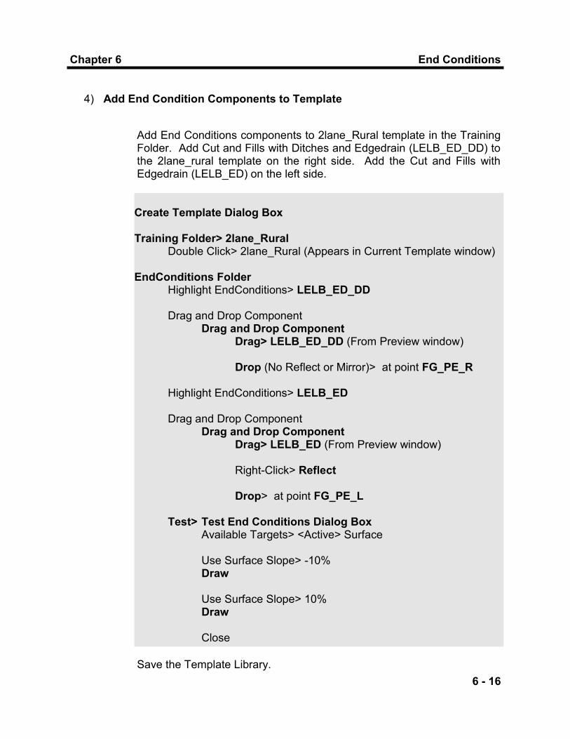
Add End Conditions components to 2lane_Rural template in the Training Folder. Add Cut and Fills with Ditches and Edgedrain (LELB_ED_DD) to the 2lane_rural template on the right side. Add the Cut and Fills with Edgedrain (LELB_ED) on the left side.
4) Add End Condition Components to Template
Create Template Dialog Box Training Folder> 2lane_Rural Double Click> 2lane_Rural (Appears in Current Template window) EndConditions Folder Highlight EndConditions> LELB_ED_DD Drag and Drop Component Drag and Drop Component Drag> LELB_ED_DD (From Preview window) Drop (No Reflect or Mirror)> at point FG_PE_R Highlight EndConditions> LELB_ED Drag and Drop Component Drag and Drop Component Drag> LELB_ED (From Preview window) Right-Click> Reflect Drop> at point FG_PE_L Test> Test End Conditions Dialog Box Available Targets> <Active> Surface Use Surface Slope> -10% Draw Use Surface Slope> 10% Draw Close
Save the Template Library.

InRoads Template Library
7 - 1

LAB
7 - 2
Chapter 7
Chapter 7
LAB
This chapter you will create a new template. You will add an end condition and test it to the original ground.

InRoads Template Library
7 - 3
LEFT side of Roadway Centerline RIGHT side of Roadway Centerline

LAB
7 - 4
Chapter 7
Exit from the file you are in, closing InRoads and checking in all the files. Open 330330_cph_typ_01.dgn, MicroStation file, for the LAB. In this file, is a typical section for Urban area with curbs and sidewalks. Open InRoads, load the alignment file and the template library from your student folder.
1) Open New MicroStation File, Restart InRoads
Create a new template called 2lane_Urban. Build this template with 3.6 m lanes at -2% slopes, 1.2 m curb offsets at -6% slopes, as per the typical section in the file you are working in. This typical section is also on page 7-3.
Student Folder 330330_fea_rwy.alg 330330_fea_rwy.itl
2) Create Urban Template with Curbs, Sidewalks, and Utility Strips
Photogrammetry Folder (Read-Only) 330330_map_pho_og.dtm 330330_map_pho_og_b.dtm
Load the original ground DTM’s, read-only from the Photogrammetry folder.

InRoads Template Library
7 - 5

LAB
7 - 6
Chapter 7
New Template> Training Folder Name> 2Lane_Urban Description> Type E100 Curbs, 1.5 m SW, 1.2 m Utility Dynamic Settings Toggle On> Apply Affixes Drag and Drop Components: Drag> PET_W/PB From Pavement_Sections Folder Drop> to Origin X=0; Y=0 (2Lane_Urban—Both Sides) Drag> PE_CO From Pavement_Sections Folder Drop> to FG_PET (Both Sides) Drag> SB_PET From Miscellaneous_Components Folder Drop> to SB_AC (Both Sides) Drag> SB_PE_CO From Miscellaneous_Components Folder Drop> to SB_PET (Both Sides) Merge Components Merge> Pavement Courses PET_L with PE_L PET_R with PE_R SUB_PET_L with SUB_PE_L SUB_PET_R with SUB_PE_R Rename Components Edit> Components Rename> TP, BN, BS, PB, SB
Add components from Pavement_Sections folder to create pavement courses. Add components from Miscellaneous_Components folder to create subbase course.
InRoads Template Library
7 - 7
LAB
7 - 8
Chapter 7
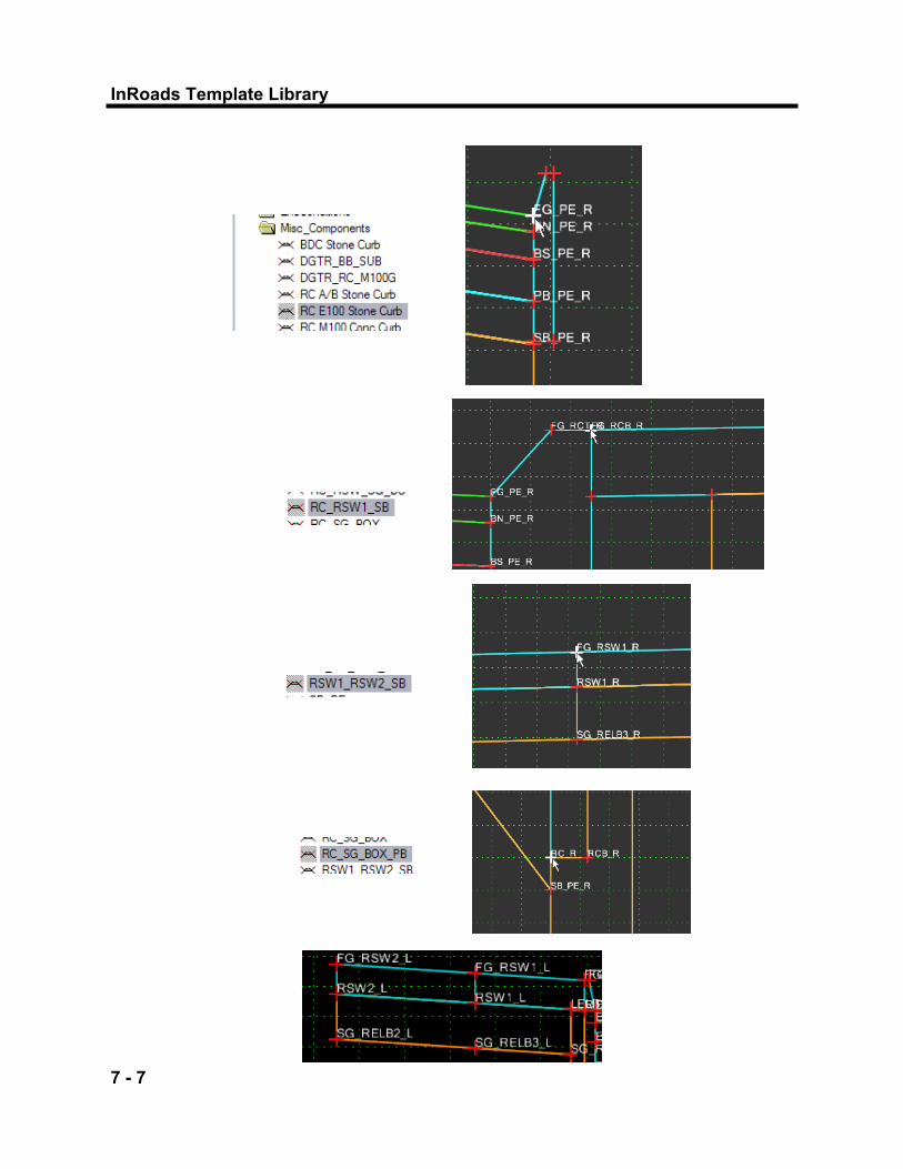
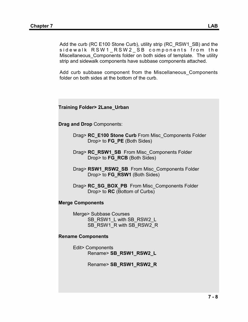
Training Folder> 2Lane_Urban Drag and Drop Components: Drag> RC_E100 Stone Curb From Misc_Components Folder Drop> to FG_PE (Both Sides) Drag> RC_RSW1_SB From Misc_Components Folder Drop> to FG_RCB (Both Sides) Drag> RSW1_RSW2_SB From Misc_Components Folder Drop> to FG_RSW1 (Both Sides) Drag> RC_SG_BOX_PB From Misc_Components Folder Drop> to RC (Bottom of Curbs) Merge Components Merge> Subbase Courses SB_RSW1_L with SB_RSW2_L SB_RSW1_R with SB_RSW2_R Rename Components Edit> Components Rename> SB_RSW1_RSW2_L Rename> SB_RSW1_RSW2_R
Add the curb (RC E100 Stone Curb), utility strip (RC_RSW1_SB) and the s i d e w a l k R S W 1 _ R S W 2 _ S B c o m p o n e n t s f r o m t h e Miscellaneous_Components folder on both sides of template. The utility strip and sidewalk components have subbase components attached. Add curb subbase component from the Miscellaneous_Components folder on both sides at the bottom of the curb.

InRoads Template Library
7 - 9

LAB
7 - 10
Chapter 7
Training Folder> 2Lane_Urban Drag and Drop Components: Drag> LELB From EndConditions Folder Drop> to FG_RSW2 (Both Sides)
Add the cu t and f i l l s lopes ’ (LELB) componen t f rom the EndConditions folder on both sides of template on the back side of the Sidewalk.
Add the Edge Drain/Underdrain Component (UD_100), from the Miscella-neous_Components folder on both sides of template.
Miscellaneous_Components> UD_100 Drag and Drop Components: Drag> UD_100 From Misc_Components Folder Drop> to SB_PE (Both Sides)

InRoads Template Library
7 - 11
LAB
7 - 12
Chapter 7
3) Edit Template Points
Change the Point Properties of Points FG_LELB_R and FG_LELB_L to a horizontal distance of 300 mm from the back of sidewalk, and the slope value to 0.000%.
Training Folder> 2Lane_Urban Edit Points> FG_LELB: Edit> FG_LELB_R Horizontal Constraint Value> 0.300 Slope Constraint Value> 0.00% Edit> FG_LELB_L Horizontal Constraint Value> -0.300 Slope Constraint Value> 0.00%
Save the Template Library.
Training Folder> 2Lane_Urban Test> End Conditions Fix Priorities> Check Priorities (renumber Priorities to Eliminate Conflicts)
Test the End Conditions of the Template. Fix existing Priority Conflicts.
4) End Condition Priorities
InRoads Template Library
7 - 13
LAB
7 - 14
Chapter 7
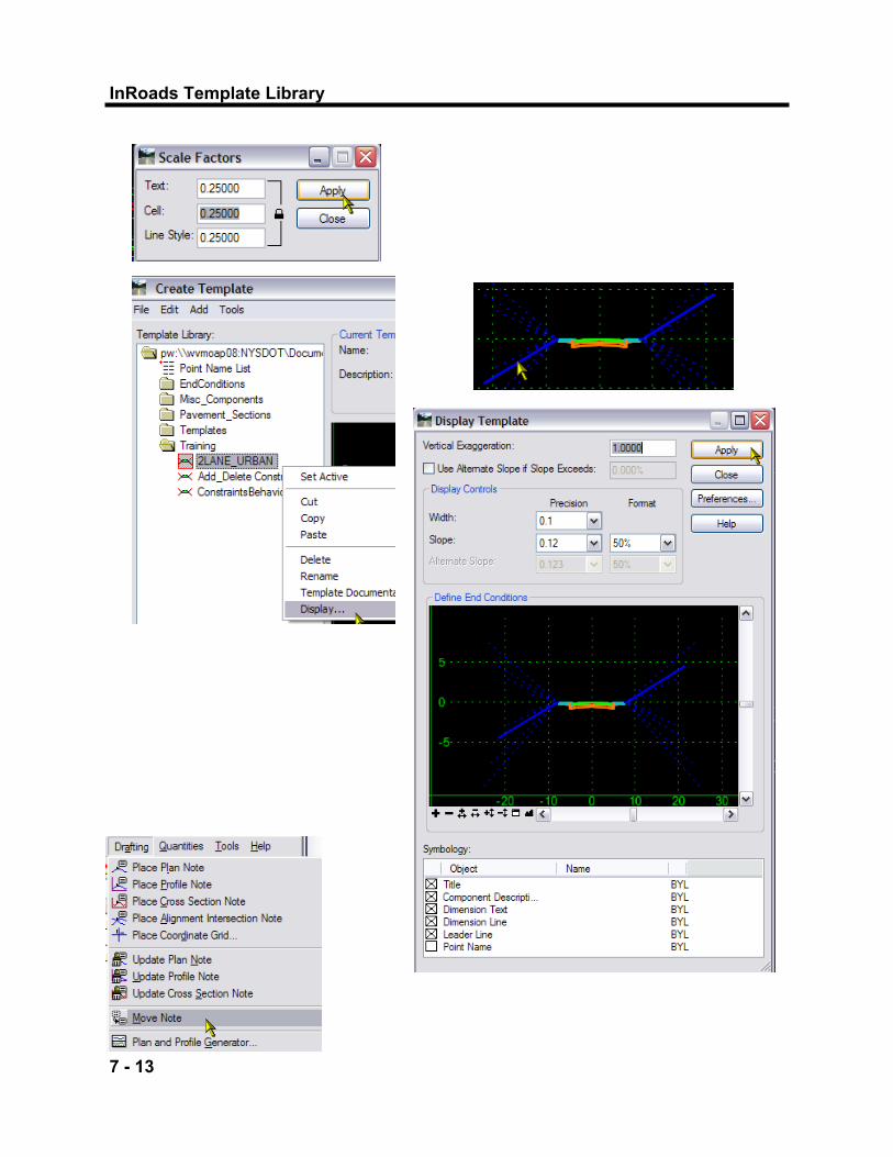
To modify placement of the Drafting Notes, use the commands in the “Drafting Notes” section. Or, use the Drafting Notes as a guide to recreate your dimensioning and text. In some instances, the Slope may not be what you wish to portray on the Typical Section, depending on the Constraints in the Template.
Display the completed Template in your MIcroStation Design File. The Annotation Scale is set for the Design File Scale Model for B-Size 50 (D-Size 25). Set Global Scale Factor for D-Size 25, which is .25 based on D-Size 1:100. Select the Template, 2LANE_URBAN from the Training Folder, and Right Click to Display. From the Display Dialog Box, there are available options for display.
Create Template Dialog Box> Training Folder Highlight> 2LANE_URBAN> Display Prompts> Identity Location Data in clear area of DGN file Create Template Dialog Box Close
5) Display Template in MicroStation DGN File