Innovative Circuit Technology Ltd. - ICT · PDF fileInnovative Circuit Technology Ltd. ... Use...
32
Innovative Circuit Technology Ltd. Dual Bus Distribution Panel Series INSTRUCTION MANUAL 855-314-000 Models: ICT200DF-12IRC ICT200DB-12IRC
Transcript of Innovative Circuit Technology Ltd. - ICT · PDF fileInnovative Circuit Technology Ltd. ... Use...

Innovative Circuit Technology Ltd.
Dual Bus Distribution Panel Series
INSTRUCTION MANUAL 855-314-000
Models:
ICT200DF-12IRC ICT200DB-12IRC

2 Innovative Circuit Technology Ltd.
WARNING Risk of serious personal injury or damage to equipment and property! Always observe the following:
Use an appropriately rated over-current protection device in line with the main battery connections to the panel
Use an appropriately rated disconnect switch or circuit breaker in line with the dc inputs to enable installation and service of the panel with the dc source disconnected
Shut off or disconnect all dc power sources before connecting or disconnecting wiring
Use wire and connectors rated for the maximum load current and size of fuse or circuit breaker, and keep cable lengths as short as practical
Carefully observe wiring polarity when making input and output connections
Securely tighten all connections
Do not attempt to service any internal parts. Refer all product service to an authorized ICT Ltd. service facility
CAUTION Risk of personal injury or damage to equipment! Always observe the following:
Install unit in a restricted access location (such as an equipment rack) to limit unintentional contact with terminals and wiring
Ensure the total power consumption of the loads does not exceed the 100A (pk) rated capacity of each power bus
Ensure load current through each output channel does not exceed 15A on 48Vdc systems, or 25A on 24V and 12Vdc systems
Do not block air inlet or outlet openings in the panel sides
Innovative Circuit Technology Ltd. 3
Contents
PRODUCT DESCRIPTION ....................................................................... 4
INSTALLATION ..................................................................................... 5
OPERATION ......................................................................................... 8
LCD Display ............................................................................................. 9
Status Indicators and Alarms ................................................................ 11
TCP/IP WEB BASED UTILITY ................................................................ 12
Status and Control ................................................................................ 14
Device Setup ......................................................................................... 15
Bus Setup .............................................................................................. 17
Output Setup ........................................................................................ 18
Network setup ...................................................................................... 19
E-mail Setup .......................................................................................... 21
Alarm setup .......................................................................................... 23
User Setup ............................................................................................ 23
Maintenance ......................................................................................... 24
MOBILE WEB APP............................................................................... 25
PASSWORD RESET .............................................................................. 25
ROUTER CONFIGURATION .................................................................. 26
TEXT MESSAGE ALARM NOTIFICATIONS .............................................. 28
TROUBLESHOOTING ........................................................................... 28
PRODUCT SPECIFICATIONS ................................................................. 30
LIMITED WARRANTY .......................................................................... 32

4 Innovative Circuit Technology Ltd.
PRODUCT DESCRIPTION The ICT Dual Bus Distribution Panel provides two 100A (pk) bus inputs with six independently controlled and monitored output channels per bus in a compact 1U high chassis for 19 inch rack mounting. Over current protection for each output is available on the front panel in two configurations; with 80VDC rated blade style fuses, or with 65VDC user replaceable magnetic-hydraulic circuit breakers. Each bus can accommodate a supply voltage from 10VDC to 60VDC, either positive or negative polarity, with a peak input current of 100A to be distributed at 25A maximum (15A for 48V systems) on each of the 6 output channels. Each channel has independent current sensing, over current protection, alarms, and output on/off control. Remote monitoring and control is available through the integrated security protected Ethernet communications port on the back of the panel. The unit has a built-in web server with an embedded web-based graphical user interface (GUI) that can be accessed using any standard commercial web browser, such as Internet Explorer or Google Chrome. The web server displays all panel information, allows full access to channel configuration settings, provides remote channel on/off control, and can be set up to send an alarm to user-defined email accounts in the event a fault occurs. The web server can also be used to configure and down load a data log of up to 30 days of time stamped event information. Full monitoring and control is also available using an SNMP (v2) based management system for larger installations. System voltage, system current, output channel current, fuse status, and alarm input status can also be monitored onsite through the front panel LCD display. Fuse status is displayed by an LED indicator located over each fuse, while breaker trip status is indicated locally by the rocker handle position and front bus alarm LED’s. Form-C alarm output contacts (C/NO/NC) are provided on the back panel for each bus to indicate all distribution panel alarms, while 5 additional alarm inputs can be used to monitor other dry-contact site sensors such as door/window opening, smoke alarms, and water detectors etc.
Model Numbers: (covered in this manual) ICT200DF-12IRC Intelligent Dual 100A Bus Fuse Distribution Panel for +/-12, 24
or 48VDC Systems ICT200DB-12IRC Intelligent Dual 100A Bus Breaker Distribution Panel for +/-12,
24 or 48VDC Systems Other Models Available: ICT200DF-12 Standard Dual 100A Bus Fuse Distribution Panel for +/- 12, 24
or 48VDC

Innovative Circuit Technology Ltd. 5
ICT200DB-12 Standard Dual 100A Bus Breaker Distribution Panel for +/-12, 24 or 48VDC
INSTALLATION Inspect your distribution panel to ensure it was not damaged in shipping, and has all accessories:
4 black plastic boots to insulate main dc power connections (shipped with unit)
4 M8 size nut/washer/split-washer sets for high current bus connector studs (shipped on unit)
2 three pin alarm output connector plugs (shipped on unit)
1 ten pin site monitor alarm input connector plug (shipped on unit)
Instruction Manual
8 ICT-BLP Breaker blanking plugs (included with ICT200DB models only) for installation in un-used breaker locations
To complete the installation you will also need appropriate fuses (FKS-ATO type) or circuit breakers (available from ICT) for each distribution channel you plan to use. Twelve 15A 80VDC FKS-ATO blade fuses are shipped with each ICT200DF-12IRC panel, while circuit breakers need to be ordered separately per the following list for use on the ICT200DB-12IRC panel: Breakers:
ICT Model Rating (65VDC) Mfg. Part Number
ICT-CB5 5A CBI Electric BDG1ED-BOLXBS-0500X-1
ICT-CB15 15A CBI Electric BDG1ED-BOLXBS-1500X-1
ICT-CB25 25A CBI Electric BDG1ED-BOLXBS-2500X-1
Carling “M” series rocker handle circuit breakers with 0.25” tab terminals and current ratings up to 25A may also be used, consult ICT for suitable part numbers. Fuses:
ICT Model Rating (80V) Mfg. Part Number
ICT- 80VF15 15A Little Fuse FKS-ATO fuse 166.7000.5156
For 12V and 24V systems standard 32VDC ATO style blade fuses may be used, with current ratings up to 25A. These fuses are widely available from multiple manufacturers.
CAUTION
Risk of personal injury or damage to equipment! Always observe the following:
Install unit in a restricted access location (such as an equipment rack) to limit unintentional contact with terminals and wiring

6 Innovative Circuit Technology Ltd.
Ensure the total power consumption of the loads does not exceed the 80A (continuous) rated capacity of each power bus
Channel output breakers or fuses must not exceed 25A max rating for 12/24VDC systems, 15A max for nominal 48VDC systems
Install only 80VDC rated fuses, 15 A max each for nominal 48Vdc systems
Install only 65VDC rated breakers, 15 A max each for nominal 48Vdc systems
Do not block air inlet or outlet openings in the panel sides
Figure 1: Back Panel Connections
Mount the Dual Bus Distribution Panel in a 19 inch equipment rack, using standard rack mounting hardware. (Not provided) On breaker equipped models install appropriately rated circuit breakers in desired channel locations by carefully inserting a breaker so that its mounting tabs securely snap into the front panel. Install the breaker blanking plugs in any unused locations. Breakers and plugs may be removed by using two small screwdrivers or similar tools to press in the top and bottom mounting tabs through the cover openings and gently prying out of the panel. On fuse equipped units change any channel fuses requiring different current ratings. (Up to 25A max on 12 or 24V systems, 15A max on 48V systems)
WARNING
Risk of serious personal injury or damage to equipment and property! Always observe the following:
Use an appropriately rated over-current protection device in line with the main battery connections to the panel
Use an appropriately rated disconnect switch or circuit breaker in line with the dc inputs to enable installation and service of the panel with the dc source disconnected
Bus A Outputs Channel 1-6
Bus B Outputs Channel 1-6
Bus A/B Input RTN Connectors (common) Bus B Input
(100A max) Bus A Input (100A max)
Site Alarm inputs 1-5
Bus A Alarm out C/NC/NO
Bus B Alarm out C/NC/NO LAN Port
10/100 Base-T

Innovative Circuit Technology Ltd. 7
Shut off or disconnect all dc power sources before connecting or disconnecting wiring
Use wire and connectors rated for the maximum load current and size of fuse or circuit breaker, and keep cable lengths as short as practical
Carefully observe wiring polarity when making input and output connections
Securely tighten all connections
Bond the panel chassis to the rack system ground, connecting a ground wire with ring tongue to the back panel ground stud. (8-32 thread) Connect Bus A loads to each output channel using suitably rated wire (10AWG max) sized for the fuse or breaker installed on the channel, stripping 10-11mm of insulation and firmly clamping in the Bus A channel 1 to 6 output connectors. Note which load is connected to each channel, for future reference. Repeat for the Bus B loads if required. The unit may be operated with either Bus A or Bus B powered, or both. NOTE!
All channel RTN lines, and the main high power Bus A and Bus B RTN terminals are common, and tied to a single internal Return bus. Bus A and Bus B inputs can be wired to a different dc voltage (10 to 60Vdc) of either polarity, but must share a common RTN voltage, normally at earth potential.
Connect the main Bus A RTN line to the external battery or power supply return using wire and ring connectors rated for up to 100A continuous current. Feed the wire through the plastic insulating cap (supplied), and connect the ring tongue to the M8 RTN stud, then securely fasten with supplied hardware. Slip the insulating cap over the high current ring tongue and RTN stud on the back panel to help prevent accidental contact with the stud connection. Connect the Bus A Input through a suitably rated disconnect switch (set in the open position) and a fuse or circuit breaker rated for 100A max continuous operation to the external battery or power supply output, using wire and connectors rated for 100A continuous current. Feed the wire through the plastic insulating cap (supplied), and connect the input ring tongue to the M8 Bus A Input stud, then securely fasten with supplied hardware and slip the cap over the ring tongue and stud to help prevent accidental contact with the input stud connection. Repeat input wiring for the Bus B input, its power source and over current protection device, if the Bus B outputs are to be used. Connect the two form-C relay bus alarm outputs to an external monitoring system if needed, by stripping and terminating 16-28AWG alarm wiring in the

8 Innovative Circuit Technology Ltd.
Alarm 3-pin connector plugs, and installing in the back panel. Each Bus Alarm output will trigger for any fuse or breaker open, or other alarm related to any channel on that bus (Factory Default). Most alarm conditions can be masked off so that they will not trigger the Alarm output if required, using the web based graphical interface. Bus Alarm Connector:
Connect up to 5 dry contact type site sensors (such as door/window sensors, smoke alarm, water detectors etc.) by stripping and terminating 16-28AWG alarm wiring and connecting to the five Site Alarm Inputs on the 10 pin removable Alarm Input Plug, if desired. These inputs may be configured to activate the panel Alarm outputs, or send an alarm e-mail on network connected units. The external sensor contacts must be voltage free; as a small sense current is supplied from the panel Alarm Input pins to detect the external contact open or closed state. Refer to the Web Based Utility section for information on how to configure and use the five Site Alarm inputs. Site Alarm Inputs:
Pin (L-R) Site Alarm Input Function
1 Input 1
c Common
2 Input 2
c Common
3 Input 3
c Common
4 Input 4
c Common
5 Input 5
c Common
Connect a standard 10/100 Base-T Ethernet cable to the RJ-45 LAN port on the back panel, if remote network control is planned or if reconfiguring the panel settings from the factory defaults is required.
OPERATION Ensure the correct fuses or circuit breakers are installed in each channel location that will be used to power a load, and switch the front panel channel breakers into the ON position (if equipped).
Alarm Pin (Bus A or B) Function
C Alarm Output common (0.5A 65Vdc max)
NC Alarm Output normally closed for alarm condition
NO Alarm Output normally open for alarm condition

Innovative Circuit Technology Ltd. 9
Figure 2: Fuse Version Front Panel Energise each bus by closing the main external breaker or disconnect device on the bus input lines. Check that the Distribution Panel LCD display powers up, the internal channel relays close after a short delay, and the connected loads are energised. (Note that all output channels on a bus will be disabled if the bus voltage drops below 6V for more than 3s. Normal operation will be restored once the bus voltage is above 8V)
Figure 3: Breaker Version Front Panel Switch off any unused internal channel relays to reduce the power consumed by the panel, using a connected computer and Web Browser. See the TCP/IP Web Based Utility section, Output On/Off Buttons. (Each channel relay consumes approximately 1W when closed)
LCD Display At power up the LCD will be displaying the Bus A main screen showing the voltage of that bus, and total current through the bus. Press the Bus A Output Select button to cycle through the Network status page, the channel output screens for that bus, (showing on/off status, voltage, and current for each output channel on the bus selected) and the five Site Alarm input status screens (if alarm inputs are enabled). Pressing the Bus B Output Select button will switch the display to the Bus B home screen. Press the button to cycle through the Network status page, each
LCD Output select buttons
Bus A Output 1-6 fuses
Bus B Output 1-6 fuses
Bus A Output 1-6 fuse open LED’s
Bus B Output 1-6 fuse open LED’s
LCD Output select buttons
Bus B Output 1-6 Circuit Breakers
Bus A Output 1-6 Circuit Breakers
BUS A Alarm LED Bus B Alarm LED
LCD Display
LCD Display

10 Innovative Circuit Technology Ltd.
channel output screen for that bus, and the five Site Alarm input status screens (if the alarm inputs are enabled). Holding either Output Select button for 2 seconds will return the display to the main screen for that bus. Holding either Output Select button for 20 seconds will reset the password to the factory default. (see Password Reset section) The LCD backlight will activate when pressing either Output Select button, and will turn off after approximately 15 minutes of inactivity. The LCD menu screens display the data as described below, in the sequence shown in Figure 4, LCD Display Screens. Main Screen Line 1: The name of the panel (user configurable via the web based graphic
interface, default is “ICT Dual Bus Panel”) Line 2: Displays the bus being monitored, Bus A or Bus B Line 3: The system voltage (voltage will blink if the voltage exceeds the Under-
voltage or Over-voltage alarm thresholds) Line 4: Total bus current (current will blink if the bus current exceeds the Over-
current alarm threshold) Network Screen Line 1: Network Status (Network Connected, No Network) Line 2: Connection type (100Base-T, 10Base-T) Line 3: IP address assigned to the panel Line 4: MAC address of the panel Output Screen (1A to 6A or 1B to 6B) Line 1: Channel number, and name of load (User configurable, default is channel
number only) Line 2: Channel output status (ENABLED, DISABLED to indicate internal relay
state or FUSE OPEN or BREAKER OFF if the over current device for the channel is tripped)
Line 3: Output voltage (voltage will blink if it exceeds the Over or Under-voltage alarm thresholds)
Line 4: Channel Output current (current will blink if it exceeds the Over, or Under-current alarm threshold for that channel)
Each output channel may be given a unique name to describe the actual load connected using the Output Setup section of the web based interface. Site Alarm Input Screen (1 to 5)

Innovative Circuit Technology Ltd. 11
The alarm screens are displayed only if the alarm input has been enabled using the Alarm Setup section of the web based graphic interface Line 1: Alarm input number (1 to 5) Line 2: Name of the alarm (if configured, default is blank) Line 4: Alarm Status (ALARM if alarm is triggered, READY when not triggered)
Figure 4: LCD Display Screens
Status Indicators and Alarms The channel LEDs (fuse version) and the Bus Alarm LEDs (breaker version) on the front panel and the Form-C Bus Alarm contacts on the back are used to indicate an alarm condition.
BUS A MENU BUS B MENU
BUS: "A" BUS: "B"
SYS VOLTAGE: 13.80V SYS VOLTAGE: -51.2V
BUS CURRENT: 76.4A BUS CURRENT: 32.5A
100 Base-T 100 Base-T
182.168.0.180 182.168.0.180
00:50:C2:02:10:2C 00:50:C2:02:10:2C
STATUS: ENABLED STATUS: ENABLED
VOLTAGE: 13.80V VOLTAGE: -51.2V
CURRENT: 14.5A CURRENT: 8.7A
STATUS: ENABLED STATUS: ENABLED
VOLTAGE: 13.80V VOLTAGE: -51.2V
CURRENT: 0.0A CURRENT: 0.0A
STATUS READY STATUS READY
STATUS ALARM STATUS ALARM
ICT DUAL BUS PANEL
Network Connected
OUTPUT 1B
OUTPUT 6B
ALARM INPUT #1
ALARM INPUT #5
ICT DUAL BUS PANEL
Network Connected
OUTPUT 1A
OUTPUT 6A
ALARM INPUT #1
ALARM INPUT #5
Alarm screens
displayed only if alarm enabled

12 Innovative Circuit Technology Ltd.
Alarm Trigger Condition Channel Output
Fuse LED
(Fuse vers)
Bus Alarm LED
1
(Breaker vers)
Bus Alarm
Contact1
Fuse Open, or Breaker Off
Fuse or breaker opens or is removed
Off On On On
Bus Under-voltage
Bus V drops below UV threshold
No change
2
Off On On
Bus Over-voltage
Bus V rises above the OV threshold
No change
Off On On
Bus Over-current
Bus current exceeds the OC threshold (default 100A)
No change
Off On On
Output Over-current
Channel output current exceeds OC threshold
Off3 Off On On
No power to Unit
Loss of bus input power source
Off Off Off On
Site Alarm Input Alarm contact on input 1 to 5
No change
No change
On On4
The unit may also be configured to send an alarm e-mail to multiple user set e-mail addresses for any of the alarm conditions, by enabling the e-mail function on each alarm setup page on the web based interface. (no e-mail will be sent if power is disconnected from the unit, due to loss of network control)
TCP/IP WEB BASED UTILITY These panels are equipped with a built in web server to enable full remote monitoring and control using any standard web browser, such as Microsoft Explorer, Google Chrome, or Mozilla Firefox. To connect with your networked panel, do the following:
1. Start Your Browser.
1 The Bus Alarm LED and Bus Alarm contact are enabled for Fuse/Breaker alarms as the
factory default setting; all other alarms must be enabled in the appropriate setup page of the web utility by selecting the “Activate Alarm Form C Contact” check box for each alarm. 2 All channel relays will be open if Bus Voltage is <6V, and recover for Bus Voltage >8V
3 The channel may be user configured to disable the output for an Over-current Alarm
4 Use the web interface to configure each alarm input to trigger either Bus A, B or both
alarm contacts

Innovative Circuit Technology Ltd. 13
2. Enter the IP address of the panel in the address field of your browser as shown.
If the panel is connected to a network with a DHCP server, the panel will be assigned an IP address automatically. To find the current address of your panel check the Network screen, line three, on the unit’s front panel LCD display. (see Fig. 4) Otherwise the panel will use the factory default IP address of 192.168.0.180, as shown above.
3. Enter your user name and password. The default Administrator user name is admin, with no password.
Once your browser is connected to the unit, the Status and Control page for the panel will be displayed, as shown. See the following section for descriptions on how to use the various monitoring, configuration, and control features available through the panel’s graphical web interface.

14 Innovative Circuit Technology Ltd.
Click on any one of the blue buttons in the menu bar on the left side of the screen to select the desired page.
Status and Control This page provides information on the voltage, current, and alarm status for each bus, along with the status of each channel output and the current being provided to each load. Each bus, or an individual output may be manually enabled or disabled by using the on screen push buttons. The status of any of the five Input Alarms for alarms that have been enabled (see Alarm Setup page) will be shown in the Alarm Input box. A grey Alarm Input indicator box shows that the sensor input is ready; a red box indicates that that external sensor is in an alarm condition. Enable Bus Button: This button will close the six channel relays on that bus, applying power to the external loads. The outputs will be enabled in a timed sequence if the power-on sequencing is enabled on the Device Setup page. Disable Bus Button: This button will open the six channel relays on that bus, cutting power to the loads. Output On/Off Buttons: Each button will toggle the internal relay for that channel, enabling or disabling the power to the load on that output. The status of
Innovative Circuit Technology Ltd. 15
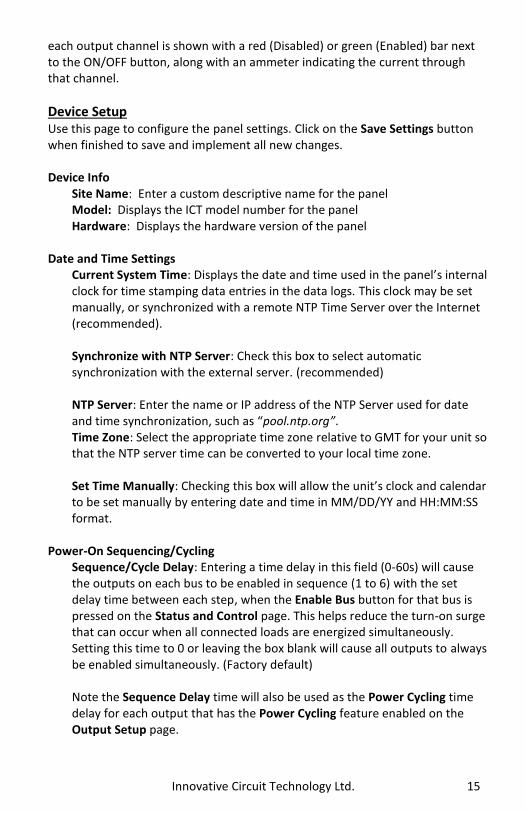
each output channel is shown with a red (Disabled) or green (Enabled) bar next to the ON/OFF button, along with an ammeter indicating the current through that channel.
Device Setup Use this page to configure the panel settings. Click on the Save Settings button when finished to save and implement all new changes. Device Info
Site Name: Enter a custom descriptive name for the panel Model: Displays the ICT model number for the panel Hardware: Displays the hardware version of the panel
Date and Time Settings
Current System Time: Displays the date and time used in the panel’s internal clock for time stamping data entries in the data logs. This clock may be set manually, or synchronized with a remote NTP Time Server over the Internet (recommended).
Synchronize with NTP Server: Check this box to select automatic synchronization with the external server. (recommended) NTP Server: Enter the name or IP address of the NTP Server used for date and time synchronization, such as “pool.ntp.org”. Time Zone: Select the appropriate time zone relative to GMT for your unit so that the NTP server time can be converted to your local time zone. Set Time Manually: Checking this box will allow the unit’s clock and calendar to be set manually by entering date and time in MM/DD/YY and HH:MM:SS format.
Power-On Sequencing/Cycling
Sequence/Cycle Delay: Entering a time delay in this field (0-60s) will cause the outputs on each bus to be enabled in sequence (1 to 6) with the set delay time between each step, when the Enable Bus button for that bus is pressed on the Status and Control page. This helps reduce the turn-on surge that can occur when all connected loads are energized simultaneously. Setting this time to 0 or leaving the box blank will cause all outputs to always be enabled simultaneously. (Factory default) Note the Sequence Delay time will also be used as the Power Cycling time delay for each output that has the Power Cycling feature enabled on the Output Setup page.
16 Innovative Circuit Technology Ltd.
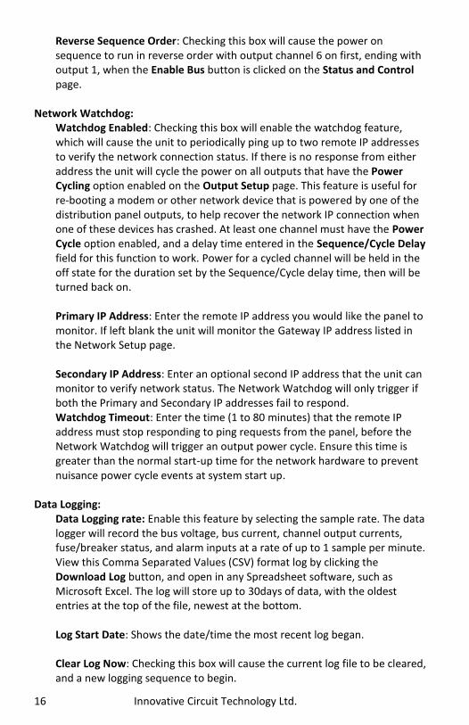
Reverse Sequence Order: Checking this box will cause the power on sequence to run in reverse order with output channel 6 on first, ending with output 1, when the Enable Bus button is clicked on the Status and Control page.
Network Watchdog:
Watchdog Enabled: Checking this box will enable the watchdog feature, which will cause the unit to periodically ping up to two remote IP addresses to verify the network connection status. If there is no response from either address the unit will cycle the power on all outputs that have the Power Cycling option enabled on the Output Setup page. This feature is useful for re-booting a modem or other network device that is powered by one of the distribution panel outputs, to help recover the network IP connection when one of these devices has crashed. At least one channel must have the Power Cycle option enabled, and a delay time entered in the Sequence/Cycle Delay field for this function to work. Power for a cycled channel will be held in the off state for the duration set by the Sequence/Cycle delay time, then will be turned back on. Primary IP Address: Enter the remote IP address you would like the panel to monitor. If left blank the unit will monitor the Gateway IP address listed in the Network Setup page.
Secondary IP Address: Enter an optional second IP address that the unit can monitor to verify network status. The Network Watchdog will only trigger if both the Primary and Secondary IP addresses fail to respond. Watchdog Timeout: Enter the time (1 to 80 minutes) that the remote IP address must stop responding to ping requests from the panel, before the Network Watchdog will trigger an output power cycle. Ensure this time is greater than the normal start-up time for the network hardware to prevent nuisance power cycle events at system start up.
Data Logging:
Data Logging rate: Enable this feature by selecting the sample rate. The data logger will record the bus voltage, bus current, channel output currents, fuse/breaker status, and alarm inputs at a rate of up to 1 sample per minute. View this Comma Separated Values (CSV) format log by clicking the Download Log button, and open in any Spreadsheet software, such as Microsoft Excel. The log will store up to 30days of data, with the oldest entries at the top of the file, newest at the bottom. Log Start Date: Shows the date/time the most recent log began. Clear Log Now: Checking this box will cause the current log file to be cleared, and a new logging sequence to begin.

Innovative Circuit Technology Ltd. 17
Bus Setup Use this page to configure each bus. Select Bus A, or Bus B in the Select a Bus to Edit box to call up the settings for that bus. Click on the Save Settings button at the bottom of the page to save any changes you make. Bus A/B Settings:
Bus Name: Enter a descriptive name for the selected bus if desired
Bus A/B Under Voltage Alarm: Under-Voltage Threshold: Enter the bus under voltage value. Bus voltage dropping below this level will trigger a Bus Under-Voltage alarm. Under-Voltage Recovery: Enter the bus voltage required to reset the alarm. Bus voltage rising above this level will clear the alarm. Activate Form-C Contact: Checking this box will cause the Alarm relay to trigger for an under voltage condition. (default) Send E-mail: Checking this box will cause the unit to send a Bus Under-Voltage alarm e-mail to the assigned address entered on the E-mail Setup page.
Bus A/B Over Voltage Alarm:
Over-Voltage Threshold: Enter the bus over-voltage value. Bus voltage rising above this level will trigger a Bus Over Voltage alarm. Activate Form-C Contact: Checking this box will cause the Alarm relay to trigger for an over voltage condition. (default) Send E-mail: Checking this box will cause the unit to send a Bus Over-Voltage alarm e-mail to the assigned address entered on the E-mail Setup page.
Bus A/B Over-Current Alarm:
Over-Current Threshold: Enter the maximum total current level for the bus. Current exceeding this level will trigger the Over-Current alarm. Activate Form-C Contact: Checking this box will cause the Alarm relay to trigger for an over-current condition. (default) Send E-mail: Checking this box will cause the unit to send a Bus Over-Current alarm e-mail to the assigned address entered on the E-mail Setup page

18 Innovative Circuit Technology Ltd.
Output Setup Use this page to configure the settings for each output channel on Bus A and Bus B. Select the output to be edited in the Select an Output to Edit box. Make any required changes, and then click on the Save Settings button at the bottom of the page to save any edits. Click on the Copy Settings to All button, to copy the settings of the selected output to all other outputs on both buses. Output Settings:
Output Label: Enter a descriptive label for the selected output channel if desired. Output State After Panel Reset: Sets the state for the output after an input power failure, or soft reset of the panel. Select one of the following:
Restore last State: Will return the output contactor to the state prior to the reset event (default)
Enable Output: Will enable the output contactor, regardless of its previous state
Disable Output: Will disable the output contactor, regardless of its previous state
Ignore Fuse/Circuit Breaker Status: Will mask the fuse or circuit breaker open circuit detection, to prevent false alarms on unused channels.
Enable Power Cycling: Check this box to enable output power cycling for the selected output, so that the output will automatically be re-enabled after the Sequence/Cycle Delay time whenever the output is disabled using the Output Off button on the Status and Control page, or when the Network Watchdog is triggered. This feature is useful for remotely resetting power to hardware required for the network connectivity of the panel. The Sequence/Cycle Delay time must be set on the Device Setup page with duration long enough for the connected network hardware to fully reset for this function to be effective. Multiple outputs that are disabled using Power Cycling will be re-enabled in sequence.
Output Load Shedding:
Enable Load Shedding: Check this box to disable this output when the bus voltage drops below the load-shedding threshold for at least 30s. This feature can be used to disconnect less critical loads to preserve back-up battery power as the battery voltage drops. Load-Shedding Threshold: Enter the voltage level at which the selected output will be disconnected.

Innovative Circuit Technology Ltd. 19
Load-Shedding Auto Recovery: Check this box to allow the output to be automatically reconnected when the bus voltage is above the Auto Recovery Threshold for at least 60s. The output must be manually re-enabled using the Output ON button on the Status and Control page if the Auto Recovery function is not enabled. Auto Recovery Threshold: Enter the voltage level at which the selected output will automatically be reconnected. This value must be at least 0.5V above the Load-Shedding Threshold voltage.
Output Over-Current Alarm:
Over-Current Threshold: Enter the over-current level. Output current above this level for at least 5s will trigger the Over-Current Alarm, and disable the output (if feature enabled). Disable this alarm by setting the threshold to 0A. Activate Form-C Contact: Checking this box will cause the Alarm relay to trigger for an over-current condition. Send E-mail: Checking this box will cause the unit to send an output Over-Current alarm e-mail to the assigned address entered on the E-mail Setup page. Disable This Output: Check this box to automatically disable the output for an Over-Current condition on the selected output. This function may be used as an electronic circuit breaker which can then be remotely reset by clicking the Output ON button on the Status and Control page.
Network setup Use this page to configure the network settings for the panel. Click on the Save Settings button at the bottom of the page to save any changes and re-boot the panel. NOTE:
Saving any changes to the network settings will cause the panel to re-boot, cycling power to all outputs.
Network:
MAC Address: Displays the MAC address assigned to the panel. It is also shown on line four of the LCD Network Status screen. Enable DHCP: Turn on this setting if your network uses a DHCP server to automatically assign IP addresses. (Enabled as default setting). To manually assign a static IP address to the unit uncheck this box, then set the following parameters.

20 Innovative Circuit Technology Ltd.
IP Address: Specify a unique IP address for the unit. Subnet Mask: Specify the mask for the subnet the panel is located on Gateway: Specify the IP address of the default router (Gateway) used for connecting attached devices to different networks. Primary DNS: Specify the IP address of the Primary DNS Server for your network. Secondary DNS: Specify the IP address of the Secondary DNS Server for your network.
Web Server: CAUTION:
Changing the web server port numbers may cause loss of communication with the panel
The following ports may be changed within a range of 1 to 65565, if required. HTTP Port: This port is used for HTTP traffic between the panel and your browser. The default HTTP port is 80, and if you change this the new HTTP Port number must be appended to the URL used to access the panel. (e.g. use URL http://192.168.0.180:8000 for IP address 192.168.0.180, port 8000) HTTPS Port: The HTTPS (HTTP Secure) protocol uses encrypted data transfer between web browsers and servers for higher security. The default HTTPS port is 443. Append any changed HTTPS port to the end of the URL for the panel. To access the panel through a secure HTTPS connection, use https:// at the start of the units URL. (e.g. https://192.168.0.180:8888 for IP address 192.168.0.180, HTTPS port 8888) UDP Port: This port is used when applying firmware upgrades to the panel. The default UDP port is 9393.
SNMP: Configure these settings if you would like to use SNMP based monitoring. SNMP (Simple Network Management Protocol) is an industry standard protocol for network management software. Enabling the SNMP function on the panel will

Innovative Circuit Technology Ltd. 21
allow standard SNMP management software to connect to the SNMP agent running on the panel and read real time system information such as bus voltage, and channel currents. The panel can send SNMP traps to the external management software when an alarm or fault occurs. The information available from the SNMP agent is described in a MIB (Management Information Base) file, which can be downloaded from the panels Help page. The unique panel MIB file must then be imported into your external SNMP management software.
Enable SNMP: Check this box to enable the SNMP agent Read Community: Enter the community string/password for read-only SNMP access. The default read community string is “public”. Trap Community: Assign the community string/password that will be sent with all traps. Some trap receivers are able to filter based on Trap Community Trap IP Addresses: Assign the IP address for up to two devices that will receive SNMP traps from the panel. Enable SNMP Write Access: Check this box to allow remote SNMP control of individual panel power outputs. If this box is unchecked information from the panel will be read-only. Write Community: Enter the community string/password for read-write SNMP access. The default write community is “write”. NOTE:
The community strings should be changed to unique passwords before enabling SNMP, as the defaults are well known.
SNMP Contact Information: Assign contact information, such as an operator name and phone number for the panel, which can be read via SNMP queries. This information is optional.
E-mail Setup Configure these settings to enable automatic e-mail notifications directly from the panel. The information required for this is available from your Network Administrator, or Internet Service Provider. (ISP)
E-mail:

22 Innovative Circuit Technology Ltd.
SMTP Server: Enter the name or the IP address of your SMTP server used for sending outgoing e-mail. (e.g. “smtp.gmail.com”) SMTP Port: Enter the port used by your SMTP server. (Normally 25) SMTP Server requires SSL: Check this box if your SMTP server requires an encrypted SSL connection. Sender E-mail Address: Enter an e-mail address that will appear as the sender for all e-mail notifications sent from the panel. Recipient E-mail Addresses: Enter one or more e-mail addresses that are to receive all e-mail notifications from the panel. Use commas to separate multiple addresses. This field can also be used to send a text message notification to a phone; see the Text Message Alarm Notifications section for further information.
SMTP User Name: Enter a SMTP user name here, if required by your SMTP server. Leave this field blank if the server does not require authentication. SMTP Password: Enter a SMTP password here, if required by your SMTP server. Leave this field blank if the server does not require authentication. Minimum E-mail Interval: Specify a minimum interval required between e-mail notifications. (Default 1 minute, range 0 to 60 minutes) This time interval is used to prevent an un-intended flood of e-mail alarm notifications that could occur when an alarm limit is incorrectly configured, for example.
General E-mail Notifications: Select these options to receive an e-mail when one or more of these events occurs.
The Distribution Panel restarts: Check this box to receive an e-mail notification when the panel restarts after a power failure or a soft reset. Load-Shedding is activated: Check this box to receive an e-mail notification when any of the outputs are disabled or enabled due the voltage crossing one of the load-shed settings configured on the Output Setup page. The Network Watchdog triggers: Check this box to receive an e-mail notification after the Network Watchdog triggers due to a loss of the network connection and the network has comes back online.

Innovative Circuit Technology Ltd. 23
Alarm setup Use this page to configure the set points of alarms to be monitored, and set the required actions when an alarm is triggered. Click on the Save Settings button at the bottom of the page to save any changes.
Circuit Breaker (Fuse) Alarm:
Activate Alarm Form-C Contact: Check this box to have the bus A alarm output trigger for any breaker or fuse on channel 1A to 6A opening, and have the bus B alarm output trigger for any breaker or fuse on channel 1B to 6B opening. Send E-mail: Check this box to cause an e-mail notification to be sent when a breaker or fuse opens on any of the output channels, stating which channel is affected. Note that the e-mail settings must be fully configured on the E-mail Setup page for this to occur.
Alarm Input #1 to #5: Configure the five Site Monitor inputs to enable the panel to monitor external contact closure events on door and window sensors, smoke alarms, etc.
Alarm Name: Enter a descriptive name for the external contact being monitored. This will be used in e-mail and front panel alarm messages. Contact Type: Select if the external alarm contact input is to be used, and what contact type is connected to each input. Choose “Normally Open” contact, “Normally Closed” contact, or “Not Used”. Activate Alarm Form-C Contact: Check this box to have both bus alarm relay outputs indicate a fault for an alarm condition on that input. Send E-mail: Check this box to have an email notification sent when one of the enabled alarm inputs is triggered, stating which input was affected. Note that the e-mail settings must be fully configured on the E-mail Setup page for this to occur.
User Setup Use this page to configure passwords for limiting access to the panel settings. Click on the Save Settings button at the bottom of the page to save any password changes. The unit has no password assigned by default, so an Administrator password should be assigned to your panel for improved security. NOTE:

24 Innovative Circuit Technology Ltd.
Record your new password for future access! If the Administrator password is lost the unit must be reset to return the password to the blank default setting, causing loss of all other user settings. See the Password Reset section for more details.
Select a User to Edit: Choose which of the two user accounts to edit.
Administrator (user name: admin) This account has full access to the panel settings. Standard User (user name: user) This account has read-only access to the panel, and cannot enable or disable the outputs, or change any of the panel settings.
New Password: Use these fields to change the password of the selected user.
New Password: Enter the new password for the chosen user. Confirm New Password: Re-enter the new password to confirm the entry.
Confirm Changes: Enter the current Administrator Password to confirm the new password changes, prior to saving the settings.
Maintenance Use this page to reset the panel (soft reset), restore the panel default settings, or send a test e-mail to verify e-mail functionality. Reset Distribution Panel: Clicking the Reset button will restart the panel. Channel output states will be restored according to the Output State after Panel Reset setting for each output on the Output Setup page. All other setting are maintained during the reset. Restore Factory Default Settings: Clicking the Restore button will restore ALL settings to the original factory default values, including the user passwords. To only restore the network settings and passwords see the Password Reset section. Send Test E-mail: Click the Send Test E-mail button to send a test e-mail to the listed e-mail recipients using the e-mail settings on the E-mail Setup page. Ping Diagnostics Tool: Use this feature to verify connectivity of any network connected device. Enter the hostname or IP address of the target device, and then click the Ping button.

Innovative Circuit Technology Ltd. 25
MOBILE WEB APP Use the mobile version of the Status and Control page to monitor and control the panel with a smartphone web browser. Access the Mobile Web App by entering the address of the panel in the address field of your browser, followed by “/m”. (e.g. https://192.168.0.180/m) You will then be prompted for your user name and password, and logged into the following Status and Control screen: For improved security you should normally use a HTTPS (secures) connection when assessing the panel over the Internet with the Mobile Web App, or use a Virtual Private Network (VPN) connection.
Mobile Web App
The Mobile Web App (shown above) provides information on bus voltage, bus current, input alarm status, and the status and current level of each of the bus output channels. Tapping on an output cell will enable or disable that output. (if you are logged in using the Administrator account) The cell will be green when enabled, red when disabled.
PASSWORD RESET Reset the Administrator password, the network, and web server settings to the original factory default values by doing the following: (the standard User password and other settings are not affected)
1. Press and hold either Output Select button on the front panel for approximately 20 seconds until Resetting is shown on the LCD.
2. Release the button

26 Innovative Circuit Technology Ltd.
3. Press and release one of the output select buttons once to view the Network Status screen on the LCD. The factory default IP address for the panel will be displayed.
ROUTER CONFIGURATION Use this section to set up a Distribution Panel with remote Internet access when located behind a router. A router allows multiple PC’s to share a single Internet connection, and must be configured correctly to forward incoming remote data to the local IP address of your panel. Example configuration using a Linksys WRT54G router: (others will be similar)
1. Log into your router and go to the port forwarding screen. In the example Linksys WRT54G router this is located in the Applications and Gaming tab. The location of the port forwarding fields may be different on your particular router. (consult the router manual for instructions)
2. Configure HTTP forwarding:
a. Enter a unique name in the Application field b. Enter the HTTP port number that the panel is using in the Start and
End fields. The default HTTP port for the panel is 80. c. Select Both under Protocol (TCP and UDP) d. Enter the local IP address of the panel (e.g. 192.168.0.180) in the IP
address field. (see step 2 of the TCP/IP Web Based Utility section to verify the panel IP address)
e. Check the Enable box, and then click on Save Settings NOTE:
Many ISP’s block access to port 80, so if your ISP does block this port you must change the HTTP port the panel uses from 80 to something else, such as 8000. (Valid port numbers are in the range of 1 to 65535) See the Network Setup section for information on assigning new network ports. You must also change the panel’s HTTP port from 80 if your local network has another device (such as a panel, or web server) already using port 80.
3. Configure HTTPS forwarding by repeating steps 2a to 2e with the HTTPS
port number that the panel is using. The default HTTPS port number is 443.
4. Set up your router to allow remote firmware upgrades to the panel by
repeating steps 2a to 2e with the UDP port number the panel is using.

Innovative Circuit Technology Ltd. 27
(default UDP port is 9393) This step is optional if firmware upgrades are to be done locally.
Router Port Forwarding Screen
5. Determine the WAN IP address of your router assigned by the ISP. With
the example router this information is on the Status tab, listed as IP Address.
NOTE:
When using a dynamic IP address the router’s WAN IP address may change from time to time without warning, depending on your ISP. In this case you should obtain a Static IP address from your ISP (it will not change) which will ensure more predictable access to the panel from a remote location. If a static IP address is not available you can use a Dynamic DNS service such as Dyn (www.dyn.com) to provide a stable address for the router.
6. To access the panel over the internet type the WAN IP address of the
router in the location/address field of your browser, followed by a colon and the HTTP port number the panel is using. (e.g. http://209.123.10.33:8000 for a router address 209.123.10.33, port 8000)
Panel Access With Router Address

28 Innovative Circuit Technology Ltd.
TEXT MESSAGE ALARM NOTIFICATIONS The panel can send alarm notifications as text messages to a cell phone by configuring the alarm e-mails to be sent to your mobile phone service provider. On the E-mail Setup page of the web based utility enter the address of your phone in the Recipient E-mail Address field. Example with an AT&T phone: enter the recipient address [email protected], replacing cellnumber with your 10 digit cell phone number. Cell address formats for some common North American mobile phone providers:
AT&T [email protected] Verizon [email protected] Sprint [email protected] T-Mobile [email protected] Virgin Mobile [email protected] Nextel [email protected] Bell Mobility [email protected] Rogers [email protected] Telus [email protected] Virgin Mobile (Can) [email protected]
TROUBLESHOOTING I am unable to access the web-based configuration utility:
Check that you are using the correct IP address for the panel by pressing an Output Select button on the front panel to view the Network Status screen on the LCD. The IP address may have been changed if DHCP is enabled.
If the Network Status screen on the LCD shows Network Not Connected check the network cable connections to the panel and the network.
Ensure you are using an industry standard “crossover” type of network cable if directly connecting a computer to the panel, and a “straight-through” type of cable to connect the panel to a network.
Ensure the network card settings on your computer are configured for accessing the IP address of the panel. To access a panel with the default IP address of 192.168.0.180 the typical network settings for your computer are:

Innovative Circuit Technology Ltd. 29
o IP Address: 192.168.0.180 o Subnet Mask: 255.255.255.0 o Gateway: 192.168.0.1
If the HTTP port of the panel has been changed, you must append the new port number to the URL used to access the panel. (See the Network Setup section) See the Password Reset section for details on how to reset the port number to the factory default value.
If your network switch allows you to manually configure port speed and duplex settings, turn-on “Auto Negotiation” for the switch port that the panel is connected to.
I forgot my password:
See the Password Reset section of the manual I am not receiving e-mails from the panel:
Verify that the Send-E-mail checkboxes are ticked for any alarm conditions for which you wish to receive e-mail notifications.
Verify your e-mail settings by going to the Maintenance page on the panel’s web utility and clicking on the Send Test E-mail button, to send a test message to your designated recipient addresses. The Send Test E-mail page will show an error message if the panel is unable to send the e-mail.
Check on the E-mail Setup page and ensure the SMTP Server field is the correct address for your e-mail provider, and the SMTP Port is correct. (Port should be 25 for most servers)
If your SMTP server requires SSL encryption, ensure the SMTP Server requires SSL checkbox is ticked. Otherwise leave blank.
If your SMTP server requires authentication ensure that the SMTP User Name and SMTP Password fields are correctly entered.

30 Innovative Circuit Technology Ltd.
PRODUCT SPECIFICATIONS Operating Voltage (either bus): 10VDC to 60VDC, or -10VDC to -60VDC Current Rating: 100A max, 80A continuous Bus A 100A max, 80A continuous Bus B 25A max, 20A Continuous per output (12/24V) 15A max, 12A Continuous per output (48V) Fuse Capacity (ICT200DF): 25A Max ATO 32V x 6 per bus (12/24V) 15A Max FKS-ATO 80V x 6 per bus (48V)
CAUTION: Use only 80Vdc rated fuses, 15A max each for nominal 48Vdc systems, or 25A max for 12 or 24V systems
NOTE: Fuses should normally be operated continuously at no more than 80% of their nominal current rating
Breaker Capacity (ICT200DB): 25A Max 65Vdc x 6 per bus (12/24V) 15A Max 65Vdc x 6 per bus (48V)
CAUTION: Use only 65Vdc rated breakers, 15A max each for nominal 48Vdc systems, or 25A max for 12 or 24V systems
NOTE: Breakers should normally be operated continuously at no more than 80% of their nominal current rating
Meter Accuracy, Voltage: Bus voltage readings +/-1% Meter Accuracy, Current: Channel current readings +/- 3% Power Consumption: < 6 W (all outputs disabled)
< 24W (all outputs enabled) Alarm Form-C Contacts: 1 output per bus, 1A 60VDc max Alarm Sensor Inputs: Five external dry contact alarm inputs,
configurable for NC or NO contacts. Applied voltage 3.3V, 0.4mA for contact closure detection
Ethernet: 10Base-T/100Base-T, RJ45 Connector SNMP: SNMP v1/v2c supported Input Connector: 4x Insulated M8 Stud, with slip-on insulating
boot, 75in-lb max torque

Innovative Circuit Technology Ltd. 31
Output Connector: 12 position cage clamp type per bus
10-22AWG, 5.22in-lb Alarm Connectors: Removable plug cage clamp type
16 – 28 AWG, 1in-lb screw torque Operating Temperature: -20°C to +60°C (Derate max bus current by 2%
per degree C above 50°C) Weight: 7 lbs (3.2kg) Warranty: 3 years Dimensions: 19.0” x 9.29” x 1.75”
483mm x 236mm x 45mm
Breaker Version
Fuse Version

LIMITED WARRANTY ICT Ltd. warrants to the original consumer purchaser that this product shall be in good working order, free from defects in materials and workmanship, for a period of three (3) years from the date of purchase. Should failure occur during the above stated time period, then ICT will, at its option, repair or replace this product at no additional charge except as set forth below. All parts, whether for repair or replacement, will be furnished on an exchange basis. All exchange pieces become the property of ICT. This limited warranty shall not apply if the ICT product has been damaged by unreasonable use, accident, negligence, disaster, service, or modification by anyone other than the ICT factory. Limited warranty service is obtained by delivering the product during the above stated three (3) year warranty period to an authorized ICT dealer or ICT factory and providing proof of purchase date. If this product is delivered by mail, you will insure the product or assume risk of loss or damage in transit, and prepay shipping charges to the factory. Every reasonable effort has been made to ensure that ICT product manuals and promotional materials accurately describe ICT product specifications and capabilities at the time of publication. However, because of ongoing improvements and updating of ICT products, ICT cannot guarantee the accuracy of printed materials after the date of publication and disclaims liability for changes, errors or omissions. If this ICT product is not in good working order, as outlined in the above warranty, your sole remedy shall be repair or replacement as provided above. In no event will ICT be liable for any damages resulting from the use of or the inability to use the ICT product, even if an ICT employee or an authorized ICT dealer has been advised of the possibility of such damages, or for any claim by any other party. ICT reserves the right to make changes without further notice to any products or documentation for improvement of reliability, function, or design. ICT Ltd. does not recommend use of its products in life support applications wherein a failure or malfunction of the product may directly or indirectly threaten life or cause injury. The user of ICT products, which are to be used in life support applications as described above, assumes all risks of such use and indemnifies ICT against all damages.
INNOVATIVE CIRCUIT TECHNOLOGY LTD. 26921 Gloucester Way
Langley, British Columbia, Canada V4W 3Y3 T 604.856.6303 F 604.856.6365 www.ict-power.com