Innovative Circuit Technology Ltd. - ICT Power · INNOVATIVE CIRCUIT TECHNOLOGY LTD. ... TCP/IP WEB...
20
INNOVATIVE CIRCUIT TECHNOLOGY LTD. 26921 GLOUCESTER WAY LANGLEY, BRITISH COLUMBIA, CANADA V4W 3Y3 T 604.856.6303 F 604.856.6365 www.ictcorporate.com Innovative Circuit Technology Ltd. Digital Series Power Supply Instruction Manual 855-317-000
-
Upload
hoangthuan -
Category
Documents
-
view
221 -
download
0
Transcript of Innovative Circuit Technology Ltd. - ICT Power · INNOVATIVE CIRCUIT TECHNOLOGY LTD. ... TCP/IP WEB...
INNOVATIVE CIRCUIT TECHNOLOGY LTD. 26921 GLOUCESTER WAY LANGLEY, BRITISH COLUMBIA,
CANADA V4W 3Y3 T 604.856.6303 F 604.856.6365 www.ictcorporate.com
Innovative Circuit Technology Ltd.
Digital Series Power Supply Instruction Manual
855-317-000

2
Rev 1.8 Jan 2015 Copyright © 2012 Innovative Circuit Technology Ltd. All rights reserved. No part of this publication may be reproduced, stored in a retrieval system or transmitted in any form or by any means, electronic, mechanical, photocopying, recording or otherwise, without the prior written consent of Innovative Circuit Technology Ltd.
39
7. LIMITED WARRANTY
ICT Ltd. warrants to the original consumer purchaser that this product shall be in good working order, free from defects in materials and workmanship, for a period of two (2) years from the date of purchase. Should failure occur during the above stated time period, then ICT will, at its option, repair or replace this product at no additional charge except as set forth below. All parts, whether for repair or replacement, will be furnished on an exchange basis. All exchange pieces become the property of ICT. This limited warranty shall not apply if the ICT product has been damaged by unreasonable use, accident, negligence, disaster, service, or modification by anyone other than the ICT factory. Limited warranty service is obtained by delivering the product during the above stated two (2) year warranty period to an authorized ICT dealer or ICT factory and providing proof of purchase date. If this product is delivered by mail, you will insure the product or assume risk of loss or damage in transit, and prepay shipping charges to the factory. Every reasonable effort has been made to ensure that ICT product manuals and promotional materials accurately describe ICT product specifications and capabilities at the time of publication. However, because of ongoing improvements and updating of ICT products, ICT cannot guarantee the accuracy of printed materials after the date of publication and disclaims liability for changes, errors or omissions. If this ICT product is not in good working order, as outlined in the above warranty, your sole remedy shall be repair or replacement as provided above. In no event will ICT be liable for any damages resulting from the use of or the inability to use the ICT product, even if an ICT employee or an authorized ICT dealer has been advised of the possibility of such damages, or for any claim by any other party. ICT reserves the right to make changes without further notice to any products or documentation for improvement of reliability, function, or design. ICT Ltd. does not recommend use of its products in life support applications wherein a failure or malfunction of the product may directly or indirectly threaten life or cause injury. The user of ICT products, which are to be used in life support applications as described above, assumes all risks of such use and indemnifies ICT against all damages. This device complies with Part 15 of the FCC Rules, class B limits. Operation is subject to the following 2 conditions: 1. This device may not cause harmful interference, and 2. This device must accept any interference received, including any
interference that may cause undesired operation.
38
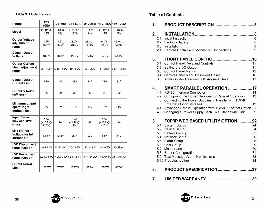
Table 3: Model Ratings
Rating 12V
100A 12V 50A 24V 50A 24V 25A 48V 25A 48V 12.5A
Model ICT1200 -
12S ICT600 -
12S ICT1200 -
24S ICT600 -
24S ICT1200 -
48S ICT600 -
48S
Output Voltage adjustment range
11.5V-15.5V
11.5V-15.5V
23.0V – 31.0V
23.0V – 31.0V
46.0V – 62.0V
46.0V – 62.0V
Default Output Voltage 13.8V 13.8V 27.6V 27.6V 55.2V 55.2V
Output Current Limit adjustment range
25 - 100A 12.5 – 50A 10 - 50A 5 – 25A 5 - 25A 2.5 – 12.5A
Default Output Current Limit
95A 48A 48A 24A 24A 12A
Output V Noise (mV rms)
30 30 30 30 60 60
Minimum output operating V during I limit
8V 8V 16V 16V 32V 32V
Input Current max at 100Vin (rms)
17A (<15A @
120V) 9A
17A (<15A @
120V) 9A
17A (<15A @
120V) 9A
Max Output Voltage for full current out
13.5V 13.5V 27V 27V 54V 54V
LVD Disconnect range (Option) 10-12.4V 10-12.4V 20-24.8V 20-24.8V 40-49.6V 40-49.6V
LVD Reconnect range (Option) 10.6-13.8V 10.6-13.8V 21.2-27.6V 21.2-27.6V 42.4-55.2V 42.4-55.2V
Output Power Limit 1350W 675W 1350W 675W 1350W 675W
3
Table of Contents
1. PRODUCT DESCRIPTION ...................................5
2. INSTALLATION ....................................................6
2.1. Initial Inspection 6
2.2. Back-up Battery 6
2.3. Installation 8
2.4. Remote Control and Monitoring Connections 9
3. FRONT PANEL CONTROL ................................ 10
3.1. Control Panel Keys and Controls 11
3.2. Setting the DC Output 11
3.3. Control Panel Menus 12
3.4. Control Panel Menu Password Reset 16
3.5. Administrator Password / IP Address Reset 17
4. SMART PARALLEL OPERATION ..................... 17
4.1. RS485 Interface Connector 18
4.2. Configuring the Power Supplies for Parallel Operation 19
4.3. Connecting the Power Supplies in Parallel with TCP/IP Ethernet Option Installed 19
4.4. Advanced Parallel Operation with TCP/IP Ethernet Option 21
4.5. Changing a Power Supply Back To a Standalone Unit 22
5. TCP/IP WEB BASED UTILITY OPTION ............. 22
5.1. System Status 24
5.2. Device Setup 24
5.3. Battery Backup 25
5.4. Network Setup 26
5.5. Alarm Setup 28
5.6. User Setup 29
5.7. Maintenance 30
5.8. Router Configuration 31
5.9. Text Message Alarm Notifications 33
5.10. Troubleshooting 34
6. PRODUCT SPECIFICATION .............................. 37
7. LIMITED WARRANTY ........................................ 39
4
WARNING! – IMPORTANT SAFETY NOTICES Risk of personal injury and property damage! You must exercise caution and follow the safety requirements listed below when using your Digital Series power supply.
• The Digital Series Power supply is intended for installation and use in a Restricted Access Location, such as a 19” equipment rack
• Installation, operation, and service to be conducted by qualified/trained service personnel only, with all wiring done in accordance with local electrical codes
• Ensure the power supply is operated from a standard 3-pin 120VAC or 240VAC 50 / 60Hz outlet with proper grounding connection
• Use 14AWG/1.5mm2 or larger wiring for AC power and bonding
connections
• Building power supply circuit must have a circuit breaker with maximum 20A rating for short circuit protection
• Ensure dc polarities and rated voltages are correct for both the load and battery connections to the unit
• Ensure all connections are properly tightened before powering up the unit to avoid over heating of connectors
• Disconnect all power sources (input power cord, and any external batteries) before attempting any service activity. Internal circuits can be energized with the power switch in the off position
• Battery current through the “BAT” terminal and internal LVD relay must not exceed the maximum current limit rating of the Digital Series power supply. Use a suitably rated over current protection device and disconnect in line with the “BAT” terminal and external battery positive. Do not connect the “BAT” terminal of multiple units in parallel
37
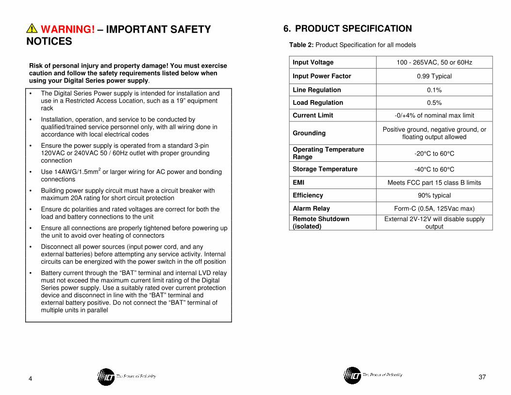
6. PRODUCT SPECIFICATION
Table 2: Product Specification for all models
Input Voltage 100 - 265VAC, 50 or 60Hz
Input Power Factor 0.99 Typical
Line Regulation 0.1%
Load Regulation 0.5%
Current Limit -0/+4% of nominal max limit
Grounding Positive ground, negative ground, or
floating output allowed
Operating Temperature Range
-20°C to 60°C
Storage Temperature -40°C to 60°C
EMI Meets FCC part 15 class B limits
Efficiency 90% typical
Alarm Relay Form-C (0.5A, 125Vac max)
Remote Shutdown (isolated)
External 2V-12V will disable supply output
36
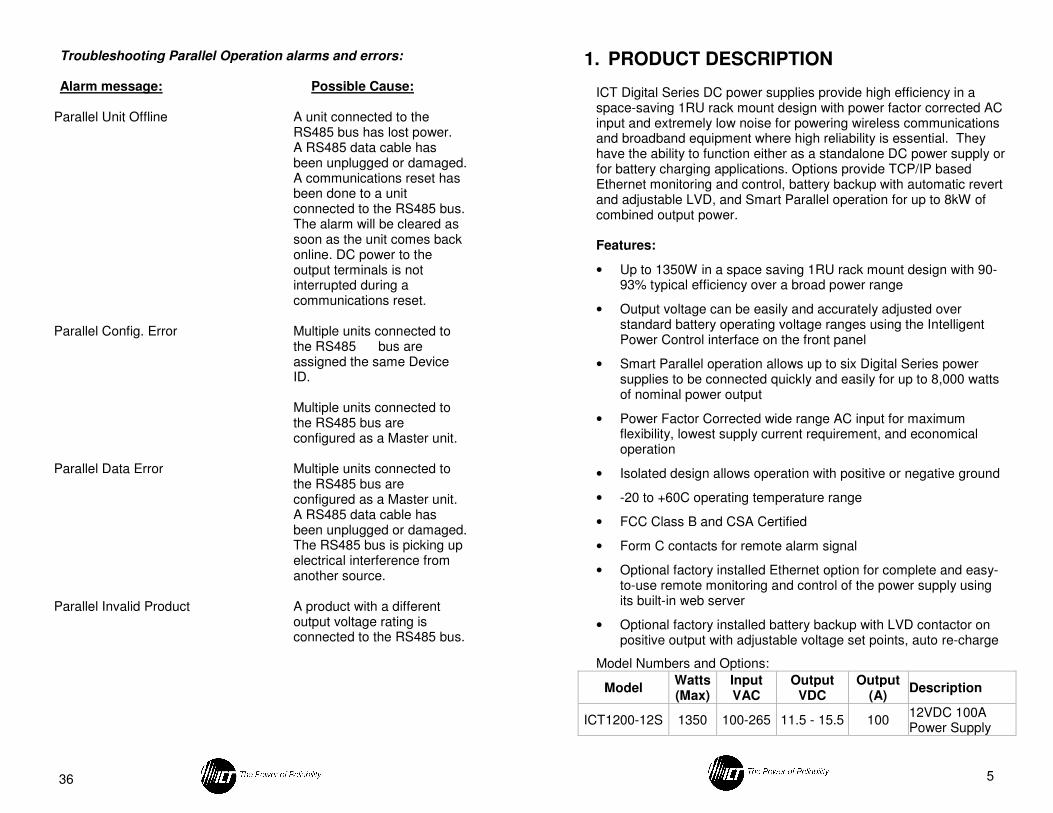
Troubleshooting Parallel Operation alarms and errors:
Alarm message: Possible Cause:
Parallel Unit Offline A unit connected to the RS485 bus has lost power. A RS485 data cable has been unplugged or damaged. A communications reset has been done to a unit connected to the RS485 bus. The alarm will be cleared as soon as the unit comes back online. DC power to the output terminals is not interrupted during a communications reset.
Parallel Config. Error Multiple units connected to
the RS485 bus are assigned the same Device ID. Multiple units connected to the RS485 bus are configured as a Master unit.
Parallel Data Error Multiple units connected to the RS485 bus are configured as a Master unit. A RS485 data cable has been unplugged or damaged. The RS485 bus is picking up electrical interference from another source.
Parallel Invalid Product A product with a different output voltage rating is connected to the RS485 bus.
5
1. PRODUCT DESCRIPTION ICT Digital Series DC power supplies provide high efficiency in a space-saving 1RU rack mount design with power factor corrected AC input and extremely low noise for powering wireless communications and broadband equipment where high reliability is essential. They have the ability to function either as a standalone DC power supply or for battery charging applications. Options provide TCP/IP based Ethernet monitoring and control, battery backup with automatic revert and adjustable LVD, and Smart Parallel operation for up to 8kW of combined output power. Features:
• Up to 1350W in a space saving 1RU rack mount design with 90-93% typical efficiency over a broad power range
• Output voltage can be easily and accurately adjusted over standard battery operating voltage ranges using the Intelligent Power Control interface on the front panel
• Smart Parallel operation allows up to six Digital Series power supplies to be connected quickly and easily for up to 8,000 watts of nominal power output
• Power Factor Corrected wide range AC input for maximum flexibility, lowest supply current requirement, and economical operation
• Isolated design allows operation with positive or negative ground
• -20 to +60C operating temperature range
• FCC Class B and CSA Certified
• Form C contacts for remote alarm signal
• Optional factory installed Ethernet option for complete and easy-to-use remote monitoring and control of the power supply using its built-in web server
• Optional factory installed battery backup with LVD contactor on positive output with adjustable voltage set points, auto re-charge
Model Numbers and Options:
Model Watts (Max)
Input VAC
Output VDC
Output (A)
Description
ICT1200-12S 1350 100-265 11.5 - 15.5 100 12VDC 100A Power Supply
6
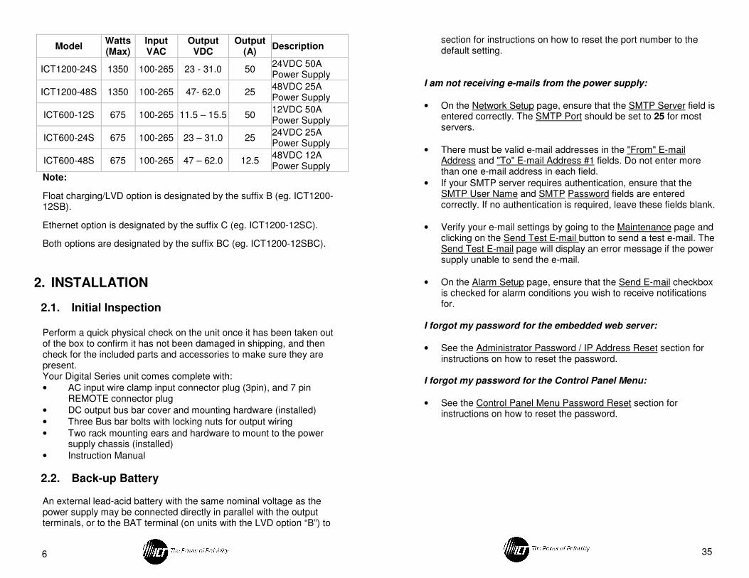
Note:
Float charging/LVD option is designated by the suffix B (eg. ICT1200-12SB).
Ethernet option is designated by the suffix C (eg. ICT1200-12SC).
Both options are designated by the suffix BC (eg. ICT1200-12SBC).
2. INSTALLATION
2.1. Initial Inspection
Perform a quick physical check on the unit once it has been taken out of the box to confirm it has not been damaged in shipping, and then check for the included parts and accessories to make sure they are present. Your Digital Series unit comes complete with:
• AC input wire clamp input connector plug (3pin), and 7 pin REMOTE connector plug
• DC output bus bar cover and mounting hardware (installed)
• Three Bus bar bolts with locking nuts for output wiring
• Two rack mounting ears and hardware to mount to the power supply chassis (installed)
• Instruction Manual
2.2. Back-up Battery An external lead-acid battery with the same nominal voltage as the power supply may be connected directly in parallel with the output terminals, or to the BAT terminal (on units with the LVD option “B”) to
Model Watts (Max)
Input VAC
Output VDC
Output (A)
Description
ICT1200-24S 1350 100-265 23 - 31.0 50 24VDC 50A Power Supply
ICT1200-48S 1350 100-265 47- 62.0 25 48VDC 25A Power Supply
ICT600-12S 675 100-265 11.5 – 15.5 50 12VDC 50A Power Supply
ICT600-24S 675 100-265 23 – 31.0 25 24VDC 25A Power Supply
ICT600-48S 675 100-265 47 – 62.0 12.5 48VDC 12A Power Supply
35
section for instructions on how to reset the port number to the default setting.
I am not receiving e-mails from the power supply:
• On the Network Setup page, ensure that the SMTP Server field is entered correctly. The SMTP Port should be set to 25 for most servers.
• There must be valid e-mail addresses in the "From" E-mail Address and "To" E-mail Address #1 fields. Do not enter more than one e-mail address in each field.
• If your SMTP server requires authentication, ensure that the SMTP User Name and SMTP Password fields are entered correctly. If no authentication is required, leave these fields blank.
• Verify your e-mail settings by going to the Maintenance page and clicking on the Send Test E-mail button to send a test e-mail. The Send Test E-mail page will display an error message if the power supply unable to send the e-mail.
• On the Alarm Setup page, ensure that the Send E-mail checkbox is checked for alarm conditions you wish to receive notifications for.
I forgot my password for the embedded web server:
• See the Administrator Password / IP Address Reset section for instructions on how to reset the password.
I forgot my password for the Control Panel Menu:
• See the Control Panel Menu Password Reset section for instructions on how to reset the password.
34
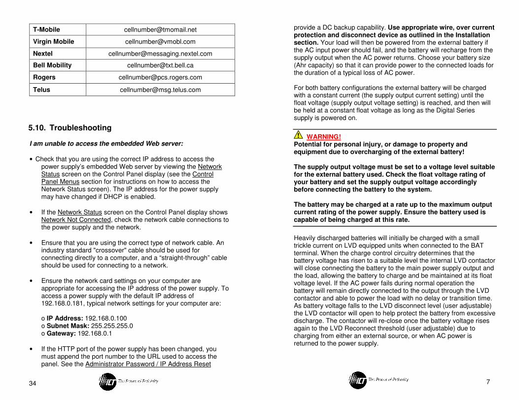
T-Mobile [email protected]
Virgin Mobile [email protected]
Nextel [email protected]
Bell Mobility [email protected]
Rogers [email protected]
Telus [email protected]
5.10. Troubleshooting
I am unable to access the embedded Web server:
• Check that you are using the correct IP address to access the power supply’s embedded Web server by viewing the Network Status screen on the Control Panel display (see the Control Panel Menus section for instructions on how to access the Network Status screen). The IP address for the power supply may have changed if DHCP is enabled.
• If the Network Status screen on the Control Panel display shows Network Not Connected, check the network cable connections to the power supply and the network.
• Ensure that you are using the correct type of network cable. An industry standard "crossover" cable should be used for connecting directly to a computer, and a “straight-through” cable should be used for connecting to a network.
• Ensure the network card settings on your computer are appropriate for accessing the IP address of the power supply. To access a power supply with the default IP address of 192.168.0.181, typical network settings for your computer are:
o IP Address: 192.168.0.100 o Subnet Mask: 255.255.255.0 o Gateway: 192.168.0.1
• If the HTTP port of the power supply has been changed, you must append the port number to the URL used to access the panel. See the Administrator Password / IP Address Reset
7
provide a DC backup capability. Use appropriate wire, over current protection and disconnect device as outlined in the Installation section. Your load will then be powered from the external battery if the AC input power should fail, and the battery will recharge from the supply output when the AC power returns. Choose your battery size (Ahr capacity) so that it can provide power to the connected loads for the duration of a typical loss of AC power. For both battery configurations the external battery will be charged with a constant current (the supply output current setting) until the float voltage (supply output voltage setting) is reached, and then will be held at a constant float voltage as long as the Digital Series supply is powered on.
WARNING! Potential for personal injury, or damage to property and equipment due to overcharging of the external battery! The supply output voltage must be set to a voltage level suitable for the external battery used. Check the float voltage rating of your battery and set the supply output voltage accordingly before connecting the battery to the system. The battery may be charged at a rate up to the maximum output current rating of the power supply. Ensure the battery used is capable of being charged at this rate.
Heavily discharged batteries will initially be charged with a small trickle current on LVD equipped units when connected to the BAT terminal. When the charge control circuitry determines that the battery voltage has risen to a suitable level the internal LVD contactor will close connecting the battery to the main power supply output and the load, allowing the battery to charge and be maintained at its float voltage level. If the AC power fails during normal operation the battery will remain directly connected to the output through the LVD contactor and able to power the load with no delay or transition time. As battery voltage falls to the LVD disconnect level (user adjustable) the LVD contactor will open to help protect the battery from excessive discharge. The contactor will re-close once the battery voltage rises again to the LVD Reconnect threshold (user adjustable) due to charging from either an external source, or when AC power is returned to the power supply.
8
Note that during battery operation with AC power off the front panel display and optional external communication ports will not be powered. Only the battery LVD circuitry will be active.
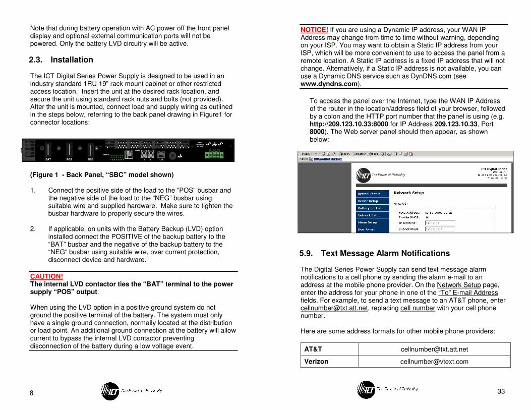
2.3. Installation
The ICT Digital Series Power Supply is designed to be used in an industry standard 1RU 19” rack mount cabinet or other restricted access location. Insert the unit at the desired rack location, and secure the unit using standard rack nuts and bolts (not provided). After the unit is mounted, connect load and supply wiring as outlined in the steps below, referring to the back panel drawing in Figure1 for connector locations:
(Figure 1 - Back Panel, “SBC” model shown)
1. Connect the positive side of the load to the ”POS” busbar and
the negative side of the load to the ”NEG” busbar using suitable wire and supplied hardware. Make sure to tighten the busbar hardware to properly secure the wires.
2. If applicable, on units with the Battery Backup (LVD) option
installed connect the POSITIVE of the backup battery to the “BAT” busbar and the negative of the backup battery to the “NEG“ busbar using suitable wire, over current protection, disconnect device and hardware.
CAUTION! The internal LVD contactor ties the “BAT” terminal to the power supply “POS” output. When using the LVD option in a positive ground system do not ground the positive terminal of the battery. The system must only have a single ground connection, normally located at the distribution or load point. An additional ground connection at the battery will allow current to bypass the internal LVD contactor preventing disconnection of the battery during a low voltage event.
33
NOTICE! If you are using a Dynamic IP address, your WAN IP Address may change from time to time without warning, depending on your ISP. You may want to obtain a Static IP address from your ISP, which will be more convenient to use to access the panel from a remote location. A Static IP address is a fixed IP address that will not change. Alternatively, if a Static IP address is not available, you can use a Dynamic DNS service such as DynDNS.com (see www.dyndns.com).
To access the panel over the Internet, type the WAN IP Address of the router in the location/address field of your browser, followed by a colon and the HTTP port number that the panel is using (e.g. http://209.123.10.33:8000 for IP Address 209.123.10.33, Port 8000). The Web server panel should then appear, as shown below:
5.9. Text Message Alarm Notifications
The Digital Series Power Supply can send text message alarm notifications to a cell phone by sending the alarm e-mail to an address at the mobile phone provider. On the Network Setup page, enter the address for your phone in one of the “To” E-mail Address fields. For example, to send a text message to an AT&T phone, enter [email protected], replacing cell number with your cell phone number.
Here are some address formats for other mobile phone providers:
AT&T [email protected]
Verizon [email protected]
32
NOTE: Many ISP’s block access to port 80. If your ISP does block port 80, you will need to change the HTTP port the panel uses from 80 to something else, such as 8000. Valid port numbers are in the range of 1 - 65535. See the Network Setup section for instructions on how to change the power supply network ports. You will also need to change the HTTP port number from 80 to something else if your local network already contains another device using port 80 such as another panel or a Web server.
3. To configure HTTPS forwarding, repeat steps 2a – 2e with the
HTTPS port number that the panel is using. If you are using the default panel port settings, the HTTPS port number is 443.
4. To set up your router to allow remote panel firmware upgrades,
repeat steps 2a – 2e with the UDP port number that the panel is using. If you are using the default panel port settings, the UDP port number is 9393. Firmware upgrades can still be applied locally if this step is skipped.
5. Before you can access the panel over the Internet, you will need
to know the WAN IP address of the router, which is assigned by your ISP. With the Linksys WRT54G router, this information is available in the Status tab, listed as “IP Address”.
9
WARNING! Battery current through the “BAT” terminal must not exceed the maximum current limit rating of the Digital Series power supply. Connect the “BAT” terminal to the external battery POSITIVE using a suitably rated over current protection and disconnect device. Otherwise damage to the unit, load, battery, and personal injury may occur if the battery is inadvertently connected in reverse polarity, or the output circuit is over loaded or shorted.
3. Connect a chassis bonding wire to the ¼ inch ground stud located on the back panel, if required, using 14AWG/1.5mm
2
or larger wire to bond the power supply chassis to the external rack system for the installation.
4. Connect appropriately rated non-energized AC power wiring
to the removable AC input connector terminal plug. (AC line or neutral to either outer connection, safety ground to the middle pin) using 14AWG/1.5mm
2 or larger wire.
5. Connect the unit to a properly grounded non-energized AC
source capable of handling the rated Digital Series input current. The building supply circuit must have a short circuit protection breaker rated 20A or less.
6. Energize the AC source, and push the front panel “ON”
switch to power up the unit, then close the backup battery disconnect device if an external battery is used.
7. Disconnect all power sources (AC input, output battery or back-up battery) before attempting any service activity.
2.4. Remote Control and Monitoring Connections
The following connections may be made to the “REMOTE” connector on the back panel for the following remote control and monitoring functionality:
CAUTION! Ensure unit is off and power is disconnected prior to making connections to the REMOTE connector terminals to avoid damaging the power supply or connected devices.
10
• Connect external Remote Shutdown control lines (TTL compatible signal) to the REM SD+ (pin 1) and REM SD- (pin 2) terminals of the “REMOTE” connector on the back panel if external on/off control of the power supply output is required. (Hi = output off, Lo = output on) (Does not alter the state of the Battery contactor on units with the LVD option)
• Connect remote voltage sense lines (16-26AWG twisted pair) from the REM SNS+ (pin 3) and REM SNS- (pin 4) terminals of the “REMOTE” connector on the back panel to the external load connections if required for tighter voltage regulation at the load. (Default voltage regulation sense point is at the output bus bars if Remote Sense is not connected).
• To keep the remote sense lead voltage compensation accuracy to within about 2% of the total load cable voltage drop, remote sense lead resistance should be kept to below 0.5ohms each. For example 15m (50ft) of 20AWG wire would be about 0.5ohms in resistance. Longer remote sense lead connections can be made using larger wire sizes, or relaxing remote sense voltage compensation accuracy expectations.
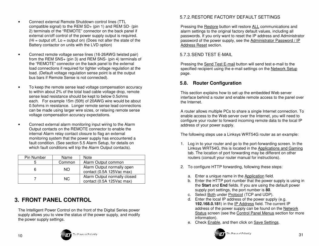
• Connect external alarm monitoring input wiring to the Alarm Output contacts on the REMOTE connector to enable the internal Alarm relay contact closure to flag an external monitoring system that the power supply has encountered a fault condition. (See section 5.5 Alarm Setup, for details on which fault conditions will trip the Alarm Output contacts).
Pin Number Name Note
5 Common Alarm Output common
6 NO Alarm Output normally open contact (0.5A 125Vac max)
7 NC Alarm Output normally closed contact (0.5A 125Vac max)
3. FRONT PANEL CONTROL
The Intelligent Power Control on the front of the Digital Series power supply allows you to view the status of the power supply, and modify the power supply settings.
31
5.7.2. RESTORE FACTORY DEFAULT SETTINGS
Pressing the Restore button will restore ALL communications and alarm settings to the original factory default values, including all passwords. If you only want to reset the IP address and Administrator password of the power supply, see the Administrator Password / IP Address Reset section.
5.7.3. SEND TEST E-MAIL Pressing the Send Test E-mail button will send test e-mail to the specified recipient using the e-mail settings on the Network Setup page.
5.8. Router Configuration
This section explains how to set up the embedded Web server interface behind a router and enable remote access to the panel over the Internet. A router allows multiple PCs to share a single Internet connection. To enable access to the Web server over the Internet, you will need to configure your router to forward incoming remote data to the local IP address of your power supply.
The following steps use a Linksys WRT54G router as an example:
1. Log in to your router and go to the port-forwarding screen. In the
Linksys WRT54G, this is located in the Applications and Gaming tab. The location of port forwarding may be different on other routers (consult your router manual for instructions).
2. To configure HTTP forwarding, following these steps:
a. Enter a unique name in the Application field. b. Enter the HTTP port number that the power supply is using in
the Start and End fields. If you are using the default power supply port settings, the port number is 80.
c. Select Both under Protocol (TCP and UDP). d. Enter the local IP address of the power supply (e.g.
192.168.0.181) in the IP Address field. The current IP address of the power supply can be found on the Network Status screen (see the Control Panel Menus section for more information).
e. Check Enable, and then click on Save Settings.
30
This page allows you to configure passwords for accessing the power supply. To save any password changes, click on Save Settings at the bottom of this page. Both the Administrator and Standard User accounts have no password assigned to them by default. For improved security, it is recommended that you assign passwords to both accounts.
NOTICE! Please record your password. If the Administrator password is lost, the power supply must be reset to return the password to the default setting. See the Password Reset section for more information.
Select a User to Edit: There are two user accounts with access to the power supply: Administrator (user name: admin) – This account has full access to the power supply.
Standard User (user name: user) – This account has view-only access to the power supply, and cannot be used to change settings. New Password: Allows you to change the password for the selected user. Confirm New Password: When changing a password, you must re-enter the new password here to confirm. Administrator Password: Enter the current Administrator password here to confirm changes.
5.7. Maintenance
This page in the Web utility allows you to reset the power supply communications, restore the power supply communications and alarm settings to the factory default settings, and send a test e-mail to verify that functionality using the Web server interface screen.
5.7.1. RESET COMMUNICATIONS
Pressing the Reset button will reset the communications controller on the power supply without interrupting DC power to the output terminals. All existing settings will be maintained.
11
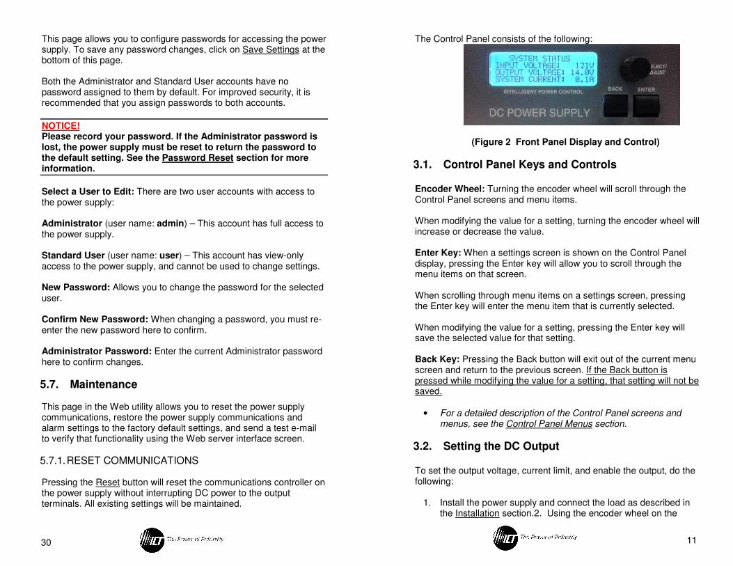
The Control Panel consists of the following:
(Figure 2 Front Panel Display and Control)
3.1. Control Panel Keys and Controls
Encoder Wheel: Turning the encoder wheel will scroll through the Control Panel screens and menu items. When modifying the value for a setting, turning the encoder wheel will increase or decrease the value. Enter Key: When a settings screen is shown on the Control Panel display, pressing the Enter key will allow you to scroll through the menu items on that screen. When scrolling through menu items on a settings screen, pressing the Enter key will enter the menu item that is currently selected. When modifying the value for a setting, pressing the Enter key will save the selected value for that setting.
Back Key: Pressing the Back button will exit out of the current menu screen and return to the previous screen. If the Back button is pressed while modifying the value for a setting, that setting will not be saved.
• For a detailed description of the Control Panel screens and menus, see the Control Panel Menus section.
3.2. Setting the DC Output
To set the output voltage, current limit, and enable the output, do the following:
1. Install the power supply and connect the load as described in the Installation section.2. Using the encoder wheel on the
12
Control Panel, scroll to the System Settings screen, and then press the Enter key.
2. Using the encoder wheel, scroll to the Output Voltage line, and
then press the Enter key.
3. Using the encoder wheel, adjust the output voltage set point to the desired voltage, and then press the Enter key.
4. Using the encoder wheel, scroll to the Current Limit line, and
then press the Enter key.
5. Using the encoder wheel, adjust the current limit set point to the desired current, and then press the Enter key.
6. Using the encoder wheel, scroll to the DC Output line, and then
press the Enter key.
7. Using the encoder wheel, change the DC output setting to On, and then press the Enter key. The DC output will now be turned on.
8. Press the Back key to return to the System Status screen.
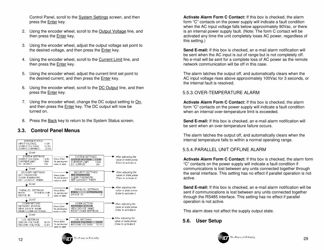
3.3. Control Panel Menus
29
Activate Alarm Form C Contact: If this box is checked, the alarm form “C” contacts on the power supply will indicate a fault condition when the AC input voltage falls below approximately 90Vac, or there is an internal power supply fault. (Note: The form C contact will be activated any time the unit completely loses AC power, regardless of this setting.) Send E-mail: If this box is checked, an e-mail alarm notification will be sent when the AC input is out of range but is not completely off. No e-mail will be sent for a complete loss of AC power as the remote network communication will be off in this case. The alarm latches the output off, and automatically clears when the AC input voltage rises above approximately 100Vac for 3 seconds, or the internal fault is resolved.
5.5.3. OVER-TEMPERATURE ALARM Activate Alarm Form C Contact: If this box is checked, the alarm form “C” contacts on the power supply will indicate a fault condition when an internal over-temperature limit is exceeded. Send E-mail: If this box is checked, an e-mail alarm notification will be sent when an over-temperature failure occurs. The alarm latches the output off, and automatically clears when the internal temperature falls to within a normal operating range.
5.5.4. PARALLEL UNIT OFFLINE ALARM
Activate Alarm Form C Contact: If this box is checked, the alarm form “C” contacts on the power supply will indicate a fault condition if communications is lost between any units connected together through the serial interface. This setting has no effect if parallel operation is not active. Send E-mail: If this box is checked, an e-mail alarm notification will be sent if communications is lost between any units connected together through the RS485 interface. This setting has no effect if parallel operation is not active. This alarm does not affect the supply output state.
5.6. User Setup
28
text message notification to a cell phone. See the Text Message Alarm Notifications section for more information. "To" E-mail Address #2: If you would like a second e-mail address to receive the e-mail notifications, enter it here. If this field is used, a valid e-mail address must also be entered in the “To” E-mail Address #1 field. SMTP User Name: If your SMTP server requires a user name and password, enter the user name here. Leave this field blank if your SMTP server does not require authentication. SMTP Password: If your SMTP server requires a user name and password, enter the password here. Leave this field blank if your SMTP server does not require authentication. Enable SNMP: Contact the factory if you would like information on using an SNMP system to monitor the power supply output.
5.5. Alarm Setup
This page allows you to choose which alarms you wish to activate. To save any changes to the alarm settings, click on Save Settings at the bottom of this page. (Note: For Digital Series units without the Ethernet option the form C relay output will always be activated for an alarm condition.) The e-mail settings on the Network Setup page must be configured correctly before any e-mail notifications can be sent.
5.5.1. DC OUTPUT FAILURE ALARM
Activate Alarm Form C Contact: If this box is checked, the alarm form “C” contacts on the power supply will indicate a fault condition when the Output Voltage or current rises above approximately 110% of the max-rated output. Send E-mail: If this box is checked, an e-mail alarm notification will be sent when a DC output failure occurs. The alarm latches the output off, and clears when the DC output is manually re-enabled.
5.5.2. AC UNDER VOLTAGE/SYSTEM FAILURE ALARM
13
Note: At any time Press the BACK key to return to the previous Screen.
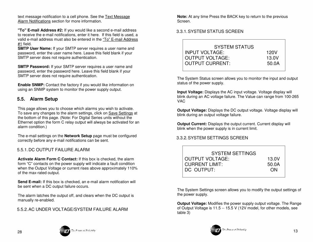
3.3.1. SYSTEM STATUS SCREEN
SYSTEM STATUS INPUT VOLTAGE: 120V OUTPUT VOLTAGE: 13.0V OUTPUT CURRENT: 50.0A
The System Status screen allows you to monitor the input and output status of the power supply. Input Voltage: Displays the AC input voltage. Voltage display will blink during an AC voltage failure. The Value can range from 100-265 VAC Output Voltage: Displays the DC output voltage. Voltage display will blink during an output voltage failure. Output Current: Displays the output current. Current display will blink when the power supply is in current limit.
3.3.2. SYSTEM SETTINGS SCREEN
SYSTEM SETTINGS OUTPUT VOLTAGE: 13.0V CURRENT LIMIT: 50.0A DC OUTPUT: ON
The System Settings screen allows you to modify the output settings of the power supply. Output Voltage: Modifies the power supply output voltage. The Range of Output Voltage is 11.5 -- 15.5 V (12V model, for other models, see table 3)
14
Current Limit: Modifies the power supply output current limit. The Range of Current Limit is 25A – 106A (12V model, for other models, see table 3) DC Output: Allows you to turn the DC Output On or Off. (Battery contactor will open when output set to Off on units with LVD option)
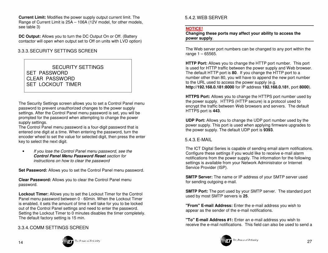
3.3.3. SECURITY SETTINGS SCREEN
SECURITY SETTINGS SET PASSWORD CLEAR PASSWORD SET LOCKOUT TIMER
The Security Settings screen allows you to set a Control Panel menu password to prevent unauthorized changes to the power supply settings. After the Control Panel menu password is set, you will be prompted for the password when attempting to change the power supply settings. The Control Panel menu password is a four-digit password that is entered one digit at a time. When entering the password, turn the encoder wheel to set the value for selected digit, then press the enter key to select the next digit.
• If you lose the Control Panel menu password, see the Control Panel Menu Password Reset section for instructions on how to clear the password
Set Password: Allows you to set the Control Panel menu password. Clear Password: Allows you to clear the Control Panel menu password.
Lockout Timer: Allows you to set the Lockout Timer for the Control Panel menu password between 0 - 60min. When the Lockout Timer is enabled, it sets the amount of time it will take for you to be locked out of the Control Panel settings and need to enter the password. Setting the Lockout Timer to 0 minutes disables the timer completely. The default factory setting is 15 min.
3.3.4. COMM SETTINGS SCREEN
27
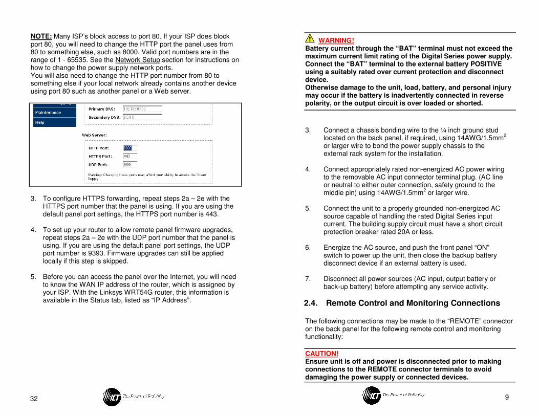
5.4.2. WEB SERVER
NOTICE! Changing these ports may affect your ability to access the power supply.
The Web server port numbers can be changed to any port within the range 1 – 65565. HTTP Port: Allows you to change the HTTP port number. This port is used for HTTP traffic between the power supply and Web browser. The default HTTP port is 80. If you change the HTTP port to a number other than 80, you will have to append the new port number to the URL used to access the power supply (e.g. http://192.168.0.181:8000 for IP address 192.168.0.181, port 8000). HTTPS Port: Allows you to change the HTTPS port number used by the power supply. HTTPS (HTTP secure) is a protocol used to encrypt the traffic between Web browsers and servers. The default HTTPS port is 443. UDP Port: Allows you to change the UDP port number used by the power supply. This port is used when applying firmware upgrades to the power supply. The default UDP port is 9393.
5.4.3. E-MAIL
The ICT Digital Series is capable of sending email alarm notifications. Configure these settings if you would like to receive e-mail alarm notifications from the power supply. The information for the following settings is available from your Network Administrator or Internet Service Provider (ISP). SMTP Server: The name or IP address of your SMTP server used for sending outgoing e-mail. SMTP Port: The port used by your SMTP server. The standard port used by most SMTP servers is 25. "From" E-mail Address: Enter the e-mail address you wish to appear as the sender of the e-mail notifications. "To" E-mail Address #1: Enter an e-mail address you wish to receive the e-mail notifications. This field can also be used to send a
26
maximum limits of an expected worst-case operating range, with AC power still present. Send E-mail: If this box is checked, an e-mail alarm notification will be sent when a battery voltage fault occurs, and AC power is present. The alarm opens the internal LVD contactor, and automatically reconnects when the battery voltage returns to an expected normal operating range.
5.4. Network Setup
This page allows you to configure the network settings of the power supply. To save any changes to the network settings, click on Save Settings at the bottom of this page and power supply will reboot.
5.4.1. NETWORK
MAC Address: Displays the MAC address assigned to the power supply.
Enable DHCP: Turn on this setting if your network is using a DHCP server to automatically assign IP addresses (DHCP is enabled by default). To manually assign a Static IP address to the power supply, uncheck the Enable DHCP box and then set the following settings.
IP Address: Specify a unique IP address for the power supply.
Subnet Mask: Specify the mask for the subnet the power supply is located on.
Gateway: Specify the IP address of the default router (gateway) used for connecting attached devices to different networks.
Primary DNS: Specify the IP address of the Primary DNS Server for your network. Secondary DNS: Specify the IP address of the Secondary DNS Server for your network.
15
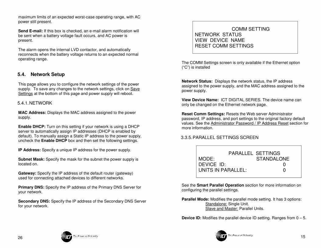
COMM SETTING NETWORK STATUS VIEW DEVICE NAME RESET COMM SETTINGS
The COMM Settings screen is only available if the Ethernet option (“C”) is installed
Network Status: Displays the network status, the IP address assigned to the power supply, and the MAC address assigned to the power supply.
View Device Name: ICT DIGITAL SERIES. The device name can only be changed on the Ethernet network page. Reset Comm Settings: Resets the Web server Administrator password, IP address, and port settings to the original factory default values. See the Administrator Password / IP Address Reset section for more information.
3.3.5. PARALLEL SETTINGS SCREEN
PARALLEL SETTINGS MODE: STANDALONE DEVICE ID: 0 UNITS IN PARALLEL: 0
See the Smart Parallel Operation section for more information on configuring the parallel settings. Parallel Mode: Modifies the parallel mode setting. It has 3 options:
Standalone: Single Unit. Slave and Master: Parallel Units.
Device ID: Modifies the parallel device ID setting. Ranges from 0 – 5.
16
Units In Parallel: If parallel operation is active, the total number of parallel units is displayed on this line. If parallel operation is not active, the display will show blank. Up to 6 Units can be connected in parallel corresponding to the value 0 – 5.
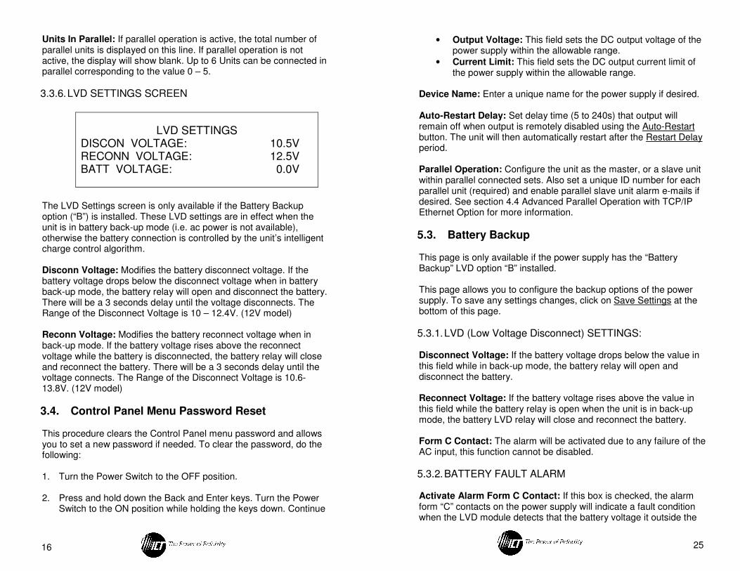
3.3.6. LVD SETTINGS SCREEN
LVD SETTINGS DISCON VOLTAGE: 10.5V RECONN VOLTAGE: 12.5V BATT VOLTAGE: 0.0V
The LVD Settings screen is only available if the Battery Backup option (“B”) is installed. These LVD settings are in effect when the unit is in battery back-up mode (i.e. ac power is not available), otherwise the battery connection is controlled by the unit’s intelligent charge control algorithm.
Disconn Voltage: Modifies the battery disconnect voltage. If the battery voltage drops below the disconnect voltage when in battery back-up mode, the battery relay will open and disconnect the battery. There will be a 3 seconds delay until the voltage disconnects. The Range of the Disconnect Voltage is 10 – 12.4V. (12V model) Reconn Voltage: Modifies the battery reconnect voltage when in back-up mode. If the battery voltage rises above the reconnect voltage while the battery is disconnected, the battery relay will close and reconnect the battery. There will be a 3 seconds delay until the voltage connects. The Range of the Disconnect Voltage is 10.6- 13.8V. (12V model)
3.4. Control Panel Menu Password Reset
This procedure clears the Control Panel menu password and allows you to set a new password if needed. To clear the password, do the following:
1. Turn the Power Switch to the OFF position.
2. Press and hold down the Back and Enter keys. Turn the Power
Switch to the ON position while holding the keys down. Continue
25
• Output Voltage: This field sets the DC output voltage of the power supply within the allowable range.
• Current Limit: This field sets the DC output current limit of the power supply within the allowable range.
Device Name: Enter a unique name for the power supply if desired. Auto-Restart Delay: Set delay time (5 to 240s) that output will remain off when output is remotely disabled using the Auto-Restart button. The unit will then automatically restart after the Restart Delay period.
Parallel Operation: Configure the unit as the master, or a slave unit within parallel connected sets. Also set a unique ID number for each parallel unit (required) and enable parallel slave unit alarm e-mails if desired. See section 4.4 Advanced Parallel Operation with TCP/IP Ethernet Option for more information.
5.3. Battery Backup
This page is only available if the power supply has the “Battery Backup” LVD option “B” installed. This page allows you to configure the backup options of the power supply. To save any settings changes, click on Save Settings at the bottom of this page.
5.3.1. LVD (Low Voltage Disconnect) SETTINGS: Disconnect Voltage: If the battery voltage drops below the value in this field while in back-up mode, the battery relay will open and disconnect the battery. Reconnect Voltage: If the battery voltage rises above the value in this field while the battery relay is open when the unit is in back-up mode, the battery LVD relay will close and reconnect the battery. Form C Contact: The alarm will be activated due to any failure of the AC input, this function cannot be disabled.
5.3.2. BATTERY FAULT ALARM Activate Alarm Form C Contact: If this box is checked, the alarm form “C” contacts on the power supply will indicate a fault condition when the LVD module detects that the battery voltage it outside the
24
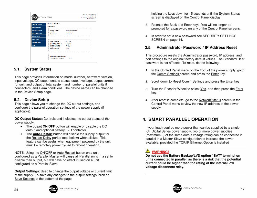
5.1. System Status
This page provides information on model number, hardware version, input voltage, DC output enable status, output voltage, output current (of unit, and output of total system and number of parallel units if connected), and alarm conditions. The device name can be changed in the Device Setup page.
5.2. Device Setup This page allows you to change the DC output settings, and configure the parallel operation settings of the power supply (if applicable).
DC Output Status: Controls and indicates the output status of the power supply.
• The output ON/OFF button will enable or disable the DC output and optional battery LVD contactor.
• The Auto-Restart button will disable the supply output for the Restart Delay period (see below) when clicked. This feature can be useful when equipment powered by the unit must be remotely power cycled to reboot operation.
NOTE: Using the ON/OFF or Auto-Restart button on a unit configured as a Parallel Master will cause all Parallel units in a set to disable their output, but will have no effect if used on a unit configured as a Parallel Slave. Output Settings: Used to change the output voltage or current limit of the supply. To save any changes to the output settings, click on Save Settings at the bottom of the page.
17
holding the keys down for 15 seconds until the System Status screen is displayed on the Control Panel display.
3. Release the Back and Enter keys. You will no longer be prompted for a password on any of the Control Panel screens.
4. In order to set a new password see SECURITY SETTINGS SCREEN on page 14.
3.5. Administrator Password / IP Address Reset
This procedure resets the Administrator password, IP address, and port settings to the original factory default values. The Standard User password is not affected. To reset, do the following:
1. In the Control Panel menu on the front of the power supply, go to
the Comm Settings screen and press the Enter key. 2. Scroll down to Reset Comm Settings and press the Enter key. 3. Turn the Encoder Wheel to select Yes, and then press the Enter
key. 4. After reset is complete, go to the Network Status screen in the
Control Panel menu to view the new IP address of the power supply.
4. SMART PARALLEL OPERATION
If your load requires more power than can be supplied by a single ICT Digital Series power supply, two or more power supplies (maximum 6) of the same output voltage rating can be connected in parallel in a Master-Slave configuration to increase the power available, provided the TCP/IP Ethernet Option is installed
WARNING! Do not use the Battery Backup/LVD option “BAT” terminal on units connected in parallel, as there is a risk that the potential current could be higher than the rating of the internal low voltage disconnect relay.
18
Otherwise damage to the unit, load, and/or personal injury may occur if the battery output current through the BAT terminal exceeds the rating for an individual supply.
CAUTION! Do not connect power supplies of different output voltage ratings in parallel, as this may cause damage to equipment or connected load.
Up to six power supplies of the same output voltage rating can be connected in parallel to provide up to six times the total output power capability. An optional bus bar set (ICT-PAR) is available to simplify connection of two units in parallel. When multiple power supplies are operating in parallel, they should all be connected together through the RS485 SHARE interface (included as part of the “Ethernet Option”), which will allow the units to share output current more equally, and allow for external network connection for the combined units using a single Ethernet port. One of the units will operate as a Master, and the remaining units are Slaves. The Slave unit’s settings will be controlled by the Master. Each unit displays its own output current and voltage on the System Status screen in the Control Panel menu. If you are running a single, standalone power supply, the Parallel Mode setting must be set to Standalone.
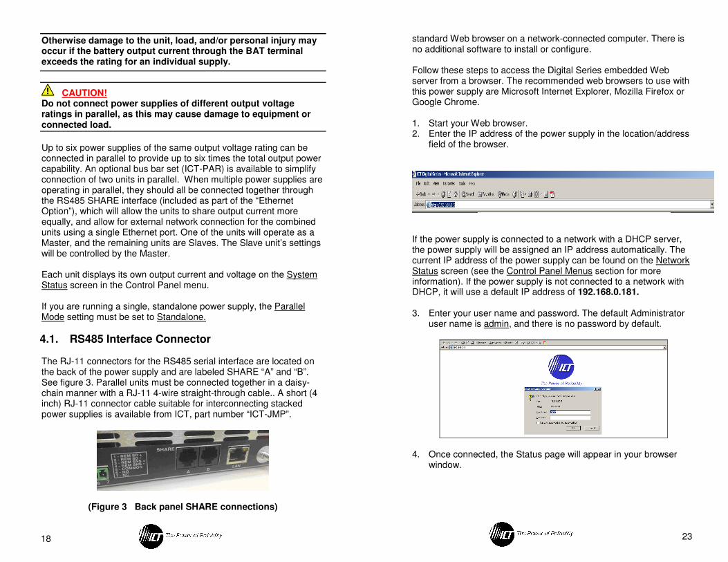
4.1. RS485 Interface Connector
The RJ-11 connectors for the RS485 serial interface are located on the back of the power supply and are labeled SHARE “A” and “B”. See figure 3. Parallel units must be connected together in a daisy-chain manner with a RJ-11 4-wire straight-through cable.. A short (4 inch) RJ-11 connector cable suitable for interconnecting stacked power supplies is available from ICT, part number “ICT-JMP”.
(Figure 3 Back panel SHARE connections)
23
standard Web browser on a network-connected computer. There is no additional software to install or configure. Follow these steps to access the Digital Series embedded Web server from a browser. The recommended web browsers to use with this power supply are Microsoft Internet Explorer, Mozilla Firefox or Google Chrome.
1. Start your Web browser. 2. Enter the IP address of the power supply in the location/address
field of the browser.
If the power supply is connected to a network with a DHCP server, the power supply will be assigned an IP address automatically. The current IP address of the power supply can be found on the Network Status screen (see the Control Panel Menus section for more information). If the power supply is not connected to a network with DHCP, it will use a default IP address of 192.168.0.181.
3. Enter your user name and password. The default Administrator
user name is admin, and there is no password by default.
4. Once connected, the Status page will appear in your browser
window.
22
4.5. Changing a Power Supply Back To a Standalone Unit
To release a unit from parallel operation and change it back to a Standalone unit, do the following: 1. Turn the Power Switch on all parallel units to the OFF position.
2. Disconnect the connections to the positive terminal (labeled
“POS”), negative terminal (labeled “NEG”), and RS485 interface (labeled “A” and B’).
3. Turn the unit’s Power Switch to the ON position.
4. In the Control Panel menu, scroll to the Parallel Settings screen
and press Enter.
5. Scroll to the Parallel Mode setting and press Enter. Scroll and choose Standalone as the parallel mode setting, then press Enter.
6. The unit is now configured as a Standalone unit. If the unit was
previously configured as a Slave unit, the System Settings Control Panel screen will now be unlocked. Note that when the Parallel Mode setting (Standalone/Master/Slave) is changed to a different setting on a unit, the DC Output of that power supply will automatically be turned OFF if it is currently enabled. The user will need to verify the output voltage/current settings, then manually enable the output.
5. TCP/IP WEB BASED UTILITY OPTION
When ordered with the TCP/IP Ethernet option “C”, the power supply will be equipped with an embedded Web server that allows you to monitor the status of the power supply, and change the power supply’s settings and configuration when the unit is powered from the AC line. (Note: Remote communication is not supported during battery backup mode when power is being supplied from an external battery.) The advantage of an embedded Web server is that it provides an interface to the power supply that can be accessed through a
19
4.2. Configuring the Power Supplies for Parallel Operation
Before connecting the power supplies together, they should all be configured for parallel operation. To do this:
1. Power each unit up independently. In the Control Panel menu,
scroll to the Parallel Settings screen and press Enter.
2. Scroll to the Parallel Mode setting and press Enter. Scroll and choose a parallel mode setting, then press Enter. One unit must be configured as a Master, and the remaining units must be set to Slave. If more than one unit is configured as a Master, the units will not operate in parallel correctly. Since the Slave units will be controlled by the Master, set the unit you would like to use to set the Output Voltage and Current Limit as the Master unit. You will be unable to set the Output Voltage or Current Limit from any of the Slave units once they are configured as Slaves.
3. Scroll to the Device ID setting and press Enter. Scroll and choose
a unique device ID number for each unit, then press Enter. If more than one unit is assigned the same device ID number, the units will not operate in parallel correctly.
NOTE: Although not recommended, it is possible to connect up to six Digital Series power supplies in parallel without using the TCP/IP Ethernet option and the Smart Parallel feature. It is important that the parallel-connected power supplies generally share the load equally. In order to achieve this, the size and length of the connecting wires should be sized properly and of the same gauge, and the wire lengths between the power supplies should be virtually identical. To ensure proper load balancing without using the Smart Parallel feature, use a voltmeter to measure the output voltage of each power supply with the load connected, and using the Intelligent Power Control interface on the front of the Digital Series power supply, adjust the output voltage level of each power supply until the outputs are within +/- 1% of each other.
4.3. Connecting the Power Supplies in Parallel with TCP/IP Ethernet Option Installed
20
WARNING! Do not use the Battery Backup/LVD option “BAT” terminal on units connected in parallel, as there is a risk that the potential load current could be higher than the rating of the internal low voltage disconnect relay. Otherwise damage to the unit, load, and/or personal injury may occur if the battery output current through the “BAT” terminal exceeds the rating for an individual supply.
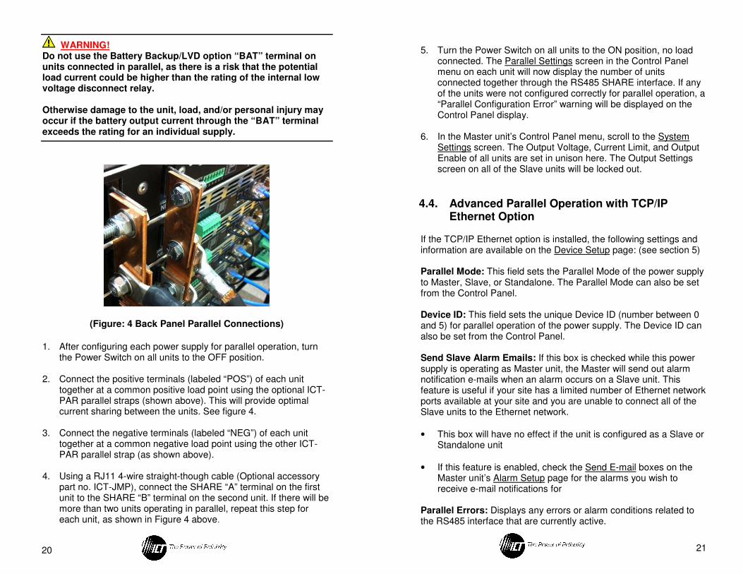
(Figure: 4 Back Panel Parallel Connections)
1. After configuring each power supply for parallel operation, turn
the Power Switch on all units to the OFF position.
2. Connect the positive terminals (labeled “POS”) of each unit together at a common positive load point using the optional ICT-PAR parallel straps (shown above). This will provide optimal current sharing between the units. See figure 4.
3. Connect the negative terminals (labeled “NEG”) of each unit together at a common negative load point using the other ICT-PAR parallel strap (as shown above).
4. Using a RJ11 4-wire straight-though cable (Optional accessory part no. ICT-JMP), connect the SHARE “A” terminal on the first unit to the SHARE “B” terminal on the second unit. If there will be more than two units operating in parallel, repeat this step for each unit, as shown in Figure 4 above.
21
5. Turn the Power Switch on all units to the ON position, no load
connected. The Parallel Settings screen in the Control Panel menu on each unit will now display the number of units connected together through the RS485 SHARE interface. If any of the units were not configured correctly for parallel operation, a “Parallel Configuration Error” warning will be displayed on the Control Panel display.
6. In the Master unit’s Control Panel menu, scroll to the System Settings screen. The Output Voltage, Current Limit, and Output Enable of all units are set in unison here. The Output Settings screen on all of the Slave units will be locked out.
4.4. Advanced Parallel Operation with TCP/IP Ethernet Option
If the TCP/IP Ethernet option is installed, the following settings and information are available on the Device Setup page: (see section 5)
Parallel Mode: This field sets the Parallel Mode of the power supply to Master, Slave, or Standalone. The Parallel Mode can also be set from the Control Panel.
Device ID: This field sets the unique Device ID (number between 0 and 5) for parallel operation of the power supply. The Device ID can also be set from the Control Panel. Send Slave Alarm Emails: If this box is checked while this power supply is operating as Master unit, the Master will send out alarm notification e-mails when an alarm occurs on a Slave unit. This feature is useful if your site has a limited number of Ethernet network ports available at your site and you are unable to connect all of the Slave units to the Ethernet network.
• This box will have no effect if the unit is configured as a Slave or Standalone unit
• If this feature is enabled, check the Send E-mail boxes on the Master unit’s Alarm Setup page for the alarms you wish to receive e-mail notifications for
Parallel Errors: Displays any errors or alarm conditions related to the RS485 interface that are currently active.