Innovative Approach for Improving Roof Crush...
10
5. LS-DYNA Anwenderforum, Ulm 2006 Innovative Approach for Improving Roof Crush Resistance Pradeep Mohan 1 , Vinay Nagabhushana 1 , Cing-Dao (Steve) Kan 1 Jon Riley 2 1 National Crash Analysis Center, The George Washington University 2 L & L Products Inc.Formatvorlage Abstract: The objective of this study is to explore and identify vehicle body design countermeasures to meet the proposed upgrade of the FMVSS 216 standard. Finite Element (FE) methods in LS-DYNA solver are used as a tool to evaluate the performance of each countermeasure. A generic FE model of a sport utility vehicle developed at the National Crash Analysis Center (NCAC/GWU) is used as an exemplar vehicle. Traditional countermeasures such as material grade and gauge change are applied to this exemplar vehicle to study the benefit of added mass in increasing the roof crush resistance. In addition, innovative countermeasures in the form of composite structural reinforcements are considered in this study. Component level three point bend tests are conducted with and without the composite reinforcements to evaluate the benefit of composite body solutions for roof crush applications. This paper provides an overview of the substantial benefits of utilizing Composite Body Solutions® (polymeric structural foam materials and their designs) in significantly improving roof crush performance. © 2006 Copyright by DYNAmore GmbH Material I - Validierung D - I - 1
-
Upload
trankhuong -
Category
Documents
-
view
214 -
download
0
Transcript of Innovative Approach for Improving Roof Crush...

5. LS-DYNA Anwenderforum, Ulm 2006
Innovative Approach for Improving Roof Crush Resistance
Pradeep Mohan 1, Vinay Nagabhushana 1, Cing-Dao (Steve) Kan 1 Jon Riley 2
1 National Crash Analysis Center, The George Washington University
2 L & L Products Inc.Formatvorlage
Abstract:
The objective of this study is to explore and identify vehicle body design countermeasures to meet the proposed upgrade of the FMVSS 216 standard. Finite Element (FE) methods in LS-DYNA solver are used as a tool to evaluate the performance of each countermeasure. A generic FE model of a sport utility vehicle developed at the National Crash Analysis Center (NCAC/GWU) is used as an exemplar vehicle. Traditional countermeasures such as material grade and gauge change are applied to this exemplar vehicle to study the benefit of added mass in increasing the roof crush resistance. In addition, innovative countermeasures in the form of composite structural reinforcements are considered in this study. Component level three point bend tests are conducted with and without the composite reinforcements to evaluate the benefit of composite body solutions for roof crush applications. This paper provides an overview of the substantial benefits of utilizing Composite Body Solutions® (polymeric structural foam materials and their designs) in significantly improving roof crush performance.
© 2006 Copyright by DYNAmore GmbH
Material I - Validierung
D - I - 1

5. LS-DYNA Anwenderforum, Ulm 2006
INTRODUCTION Vehicle rollover is a rare event on US roads compared to other crash types. According to the
National Highway Traffic Safety Agency (NHTSA) [1], rollover accounted for only 3% of 11 million crashes in 2002. However, one third of the 42,000 fatalities occurred during a rollover. Moreover, out of 418,000 occupants exposed to a rollover, more than half suffer minor or moderate injuries, about 17,000 are seriously or critically injured, and more than 10,000 are killed. Rollover is a particularly harmful event that induces 33% of the injury costs associated with all vehicle crashes. The fatality and injury rate makes rollover crashes an important issue in vehicle safety.
The current Federal Motor Vehicle Safety Standard (FMVSS) No. 216 [2] which has been in
effect since 1971, requires that a passenger car roof withstand a load of 1.5 times the vehicle’s unloaded weight in kilograms multiplied by 9.8 or 22,240 Newtons, whichever is less, to either side of the forward edge of the vehicle’s roof with no more than 125 mm of crush. The same standard also applies to light trucks and vans (LTV’s) with a GVWR of 2,722 kilograms or less, without the 22,240 Newton force limit. This standard has been criticized for being a static test which does not represent real-world rollover events.
Since a full-scale rollover test has yet to be shown to be repeatable, NHTSA has investigated
other possible test procedures for upgrading the FMVSS No. 216. One option to upgrade FMVSS No. 216 is to continue using a static test that is set to some dynamically equivalent severity. A static test is advantageous by its repeatability. Hence, NHTSA is proposing the following upgrades to the current FMVSS 216 standard;
1. NHTSA is proposing to extend the application of the standard to vehicles with a Gross Vehicle Weight Rating (GVWR) of 4,536 kilograms (10,000 pounds) or less.
2. NHTSA is proposing to increase the applied force to 2.5 times each vehicle’s unloaded weight, and to eliminate an existing limit on the force applied to passenger cars.
3. NHTSA is proposing to replace the current limit on the amount of roof crush with a new requirement for maintenance of enough headroom to accommodate a mid-size adult male occupant.
This NPRM will have a significant impact on the vehicle design. Countermeasures will have to be developed by the automotive industry to meet the upgraded FMVSS 216. It is generally agreed that the A-pillar, B-pillar, Roof Rail, Front Header sections and joints are the key areas to be strengthened to meet the proposed standard. In this study, a finite element model of an exemplar SUV is used to strengthen the above mentioned critical areas using traditional and innovative countermeasures to improve roof strength. This paper presents the results of this study.
The test procedure and devices for quasi-static roof crush testing are described in FMVSS No. 216, Roof Crush Resistance. The quasi-static load on the roof is applied with a rigid, unyielding flat rectangular plate, 762 mm x 1829 mm (30" x 72"). This plate is oriented at a longitudinal angle of 5 deg below horizontal and a lateral angle of 25 deg below the horizontal, as shown in Figure 1. The plate is positioned above the vehicle so that the first contact point on the roof is on the longitudinal centerline of the plate at a point 254 mm (10") behind the forward most edge of the plate. This procedure is intended to simulate the roof contact with the ground in an actual rollover event. A quasi-static load is then applied to the roof at a rate of 13 mm (.5") per second and in a direction normal to the load plate surface.
Figure 1: FMVSS 216 Test Setup
© 2006 Copyright by DYNAmore GmbH
Material I - Validierung
D - I - 2

5. LS-DYNA Anwenderforum, Ulm 2006
MODEL DETAILS The full vehicle finite element model used in this study was developed at the National Crash Analysis Center (NCAC/GWU) under a co-operative agreement between FHWA/NHTSA and GWU. The FE model is shown in figure 2. This model has been validated to a frontal NCAP test conducted by NHTSA. The validation report and the FE model is available for download from the NCAC website (www.ncac.gwu.edu). The FE model has also been validated to a FMVSS 216 test to establish the baseline performance of this exemplar vehicle. The simulation setup and the results from the simulation are shown in figures 3 and 4. The rails are constrained using the *BOUNDARY_SPC [3] at the locations specified in the test report. The rigid plate is defined using the *RIGIDWALL [3] option and is positioned as defined in the FMVSS 216 test protocol. The model shows good correlation compared to the test till about 75 mm of plate deflection. There is slight variation in the force after about 75 mm of plate deflection. This is due to slight variations in the deformation mode and the failure of the windshield. This state of validation is considered sufficient for this study.
Figure 2: Finite Element Model of the Exemplar Vehicle
Figure 3: Simulation Setup
© 2006 Copyright by DYNAmore GmbH
Material I - Validierung
D - I - 3

5. LS-DYNA Anwenderforum, Ulm 2006
Figure 4: FMVSS 216 Test vs. Simulation
COUNTERMEASURES
Traditional Steel Solutions
In order to evaluate the benefits of an innovative solution, it was first necessary to evaluate the
possibilities that could be accomplished without having to re-design the entire vehicle structure. This limits the range of changes that could be done for the existing design to either a gauge upgrade or material upgrade or a combination of both. Some of the structural parts along with its baseline material grade and gauge are shown in figure 5.
B-Pillar-reinforcement, gauge=1.36mm, mat=370Mpa
B-Pillar-inner, gauge=1.1mm, mat=370Mpa
Rear-Quarter-panel-inner, gauge=0.89mm, mat=290Mpa
Roof-rail-inner, gauge=1.1mm, mat=370Mpa
A-Pillar-inner, gauge=1.1mm, mat=370Mpa
Front-Body-Hinge-Pillar-inner, gauge=1.215mm, mat=320Mpa
Front-Body-Hinge-Pillar-reinforcement, gauge=1.1mm, mat=370Mpa
Front-Header-lower, gauge=0.85mm, mat=200Mpa
Front-Header-Upper, gauge=1.0mm, mat=370Mpa
Roof-Bow-Front, gauge=2.47mm, mat=320Mpa
Roof-Bow-Center, gauge=2.235mm, mat=320Mpa
Roof-Bow-Rear, gauge=2.242mm, mat=240Mpa
Figure 5: Structural parts of the exemplar vehicle
The table below shows the DOE simulations for different gage and grade changes. A-pillar inner, B-pillar reinforcement, roof rail inner and front header were identified as the key structural members that had to be strengthened to improve roof crush performance. The gage changes were limited to 1.5 times the baseline gage. The material was upgraded from high strength steel (370 Mpa yield) to boron steel (1200 Mpa yield). Boron steel is about four times stronger than average high-strength steel. But the process used to make it that strong has some disadvantages in forming and welding. The advantages and disadvantages of boron steel are beyond the scope of this current
© 2006 Copyright by DYNAmore GmbH
Material I - Validierung
D - I - 4

5. LS-DYNA Anwenderforum, Ulm 2006
study, nonetheless it is used in this study as it seems to be a common method to strengthen structural members.
Table 1: DOE of material grade and gage changes
Iterations A-pillar inner
B-Pillar reinf.
Roof-Rail Inner
Front Header Lower
A-plr inner mat grade
B-plr reinf. mat grade
Roof Rail inner mat grade
Front Header mat grade
1 1.1mm 1.360mm 1.1mm 1.0mm (370 MPA) Boron (1200 Mpa) (370 MPA) (370 MPA)
2 1.1mm 1.360mm 1.1mm 1.0mm Boron (1200 Mpa)
Boron (1200 Mpa)
Boron (1200 Mpa)
Boron (1200 Mpa)
3 1.65mm 1.8mm 1.65mm 1.5mm Boron (1200 Mpa)
Boron (1200 Mpa)
Boron (1200 Mpa)
Boron (1200 Mpa)
4 (370 MPA) (370 MPA) (370 MPA) (370 MPA)1.65mm 1.8mm 1.65mm 1.5mm
The roof crush performance for the various steel solutions is shown in figure 6. The material upgrade to boron with the baseline material gages does offer higher level of resistance compared the baseline simulation, yet, it does not meet the proposed upgrade of FMVSS 216. The roof crush resistance offered by material up gauge is higher compared to just the grade change. But, combination of both the gage change and grade change to boron increases the roof strength and meets the 2.5 times unloaded vehicle weight requirement of the upgraded standard.
Figure 6: Roof crush performance with traditional steel solutions
Innovative Solutions
Alternative innovative solutions were evaluated to match the roof crush performance that was
observed with Boron material grade and gauge change in the exemplar vehicle. The alternate solution had to have the high strength to weight ratio to strengthen the roof structure. One such alternative solution is Composite Body Solutions (CBS®). Since the main structural components of the vehicle undergo bending during roof crush, a 3-point bend test was developed to understand the behavior of the CBS® material. The 3-point bend test was done on a structural section similar in construction to the B-pillar. A brief introduction of the CBS® material is discussed in the following section.
To reinforce an automotive body structure, the traditional approach has been to add steel
reinforcements and/or address the metal grade, gage and/or geometry. However, there are instances in which these traditional steel solutions become non-trivial or even infeasible due to manufacturing, processing or other limitations. Another reason may involve timing constraints. Problems are often discovered too late in the vehicle design process. This can eliminate some steel solutions because there is not enough time to fabricate the required steel stamping die tools. In many of these cases
© 2006 Copyright by DYNAmore GmbH
Material I - Validierung
D - I - 5
5. LS-DYNA Anwenderforum, Ulm 2006
where a traditional metal solution is either non-trivial or simply not feasible, CBS® technologies provide a viable, efficient and cost-effective solution. Due to these benefits the growing area of CBS® development is “hybrid” solutions. The coupling of this technology along with traditional steel concepts is being adopted earlier in the design process and is becoming the design of choice.
Composite Body Solutions® can be effective in building load-bearing structures. They utilize
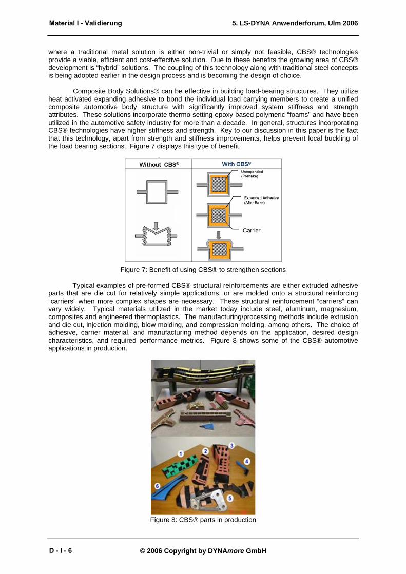
heat activated expanding adhesive to bond the individual load carrying members to create a unified composite automotive body structure with significantly improved system stiffness and strength attributes. These solutions incorporate thermo setting epoxy based polymeric “foams” and have been utilized in the automotive safety industry for more than a decade. In general, structures incorporating CBS® technologies have higher stiffness and strength. Key to our discussion in this paper is the fact that this technology, apart from strength and stiffness improvements, helps prevent local buckling of the load bearing sections. Figure 7 displays this type of benefit.
Figure 7: Benefit of using CBS® to strengthen sections
Typical examples of pre-formed CBS® structural reinforcements are either extruded adhesive parts that are die cut for relatively simple applications, or are molded onto a structural reinforcing “carriers” when more complex shapes are necessary. These structural reinforcement “carriers” can vary widely. Typical materials utilized in the market today include steel, aluminum, magnesium, composites and engineered thermoplastics. The manufacturing/processing methods include extrusion and die cut, injection molding, blow molding, and compression molding, among others. The choice of adhesive, carrier material, and manufacturing method depends on the application, desired design characteristics, and required performance metrics. Figure 8 shows some of the CBS® automotive applications in production.
Figure 8: CBS® parts in production
© 2006 Copyright by DYNAmore GmbH
Material I - Validierung
D - I - 6

5. LS-DYNA Anwenderforum, Ulm 2006
CBS® can be used as a snap-on piece to enhance the roof-crush performance in existing vehicle structures. Some of the other benefits are its high strength to weight ratio, to improve stiffness, to reduce noise and vibration etc. The CBS®, when applied to vehicle body, helps to maintain the various sections when subjected to multiple low velocity impacts. This would greatly reduce the roof intrusion into the occupant compartment area.
For development purposes and to quantify the effect of several variables, a generic specimen
was fabricated for testing. Figure 9 shows the cross-section of the specimen. This traditional section has a three layer steel construction with an inner, outer and reinforcement. This design allows for the study of grade, gage and CBS® cavity insert’s effect on overall performance.
Figure 9: Typical section considered for testing
The test setup for this portion of the study was a standard 3-point bend as shown in Figure 10.
Initial baseline testing was performed to understand the relative improvements of reinforcing cavity A, B or both versus a baseline empty metal section. The baseline section is comprised of 1 mm high strength low alloy (HSLA) steel for the inner, outer and reinforcement. The first series of testing involved characterizing the baseline section without any structural reinforcement. The grade and gage of the metal inner, outer and reinforcement were parametrically changed to study the load bearing capacity of the section. The metal inner and reinforcement were up gauged to 2 mm. Two different material grades were considered, the DP590 and the cold rolled steel (CRS). Figure 11 shows the relative effects of gage and grade. It was observed that increasing the gage provides the maximum load bearing capacity to the section when compared to increasing the grade of the steel. The second series of testing involved reinforcing cavity A and/or cavity B with CBS® for the baseline section. The CBS® solutions used in this series of testing utilized glass reinforced nylon as the structural carrier. It was observed that reinforcing the cavity has dramatic improvements in the load bearing capacity of the section as shown in Figure 12.
Figure 10: 3-point bend test setup
© 2006 Copyright by DYNAmore GmbH
Material I - Validierung
D - I - 7

5. LS-DYNA Anwenderforum, Ulm 2006
Figure 11: Effect of change in grade and gage
Figure 12: Effect of filling cavity A and B with CBS®
Sub system finite element simulations were conducted to characterize the material properties and modeling techniques to accurately capture the behavior of CBS® parts. The simulation setup of the 3-point bend test is shown in figure 13. Three sub-system simulations were conducted
1. Empty section with all three metals at 370 Mpa yield 2. Empty section with boron (1200 Mpa) metal inner reinforcement 3. CBS® filled section with all three metals at 370 Mpa yield
The epoxy adhesive for the structural reinforcement was modeled using *MAT_HONEYCOMB [3] and the 33% short glass nylon was modeled using *MAT_PIECEWISE_LINEAR_PLASTICITY [3]. The structural reinforcement was tied to the cavity using *CONTACT_TIED_NODES_TO_SURFACE [3]. The force-deflection for the above simulations is shown in figure 14.
© 2006 Copyright by DYNAmore GmbH
Material I - Validierung
D - I - 8

5. LS-DYNA Anwenderforum, Ulm 2006
Figure 13: 3-point bending, simulation setup
High Strength Steel (370mpa)
Boron Steel (1120mpa)
CBS Solution
High Strength Steel (370mpa)
Boron Steel (1120mpa)
CBS Solution
Figure 14: 3-point bending, F-d characteristics
From the component tests and simulations, it was evident that the CBS® structural reinforcement significantly strengthens the section. A CBS® part was designed to fit the a-pillar, b-pillar and roof rail cavity for this exemplar vehicle. Similar modeling techniques as followed in the sub-system simulation were applied for the full vehicle simulation. The roof crush performance with the CBS® structural reinforcement is shown in figure 15. The part can be further optimized to reduce mass and strengthen the local buckle points. The component level tests and full scale finite element simulations show that CBS® could be viable alternatives to locally strengthen the load bearing sections to improve roof strength.
© 2006 Copyright by DYNAmore GmbH
Material I - Validierung
D - I - 9

5. LS-DYNA Anwenderforum, Ulm 2006
Figure 15: Roof crush performance with CBS® solution
CONCLUSIONS
The focus of this study was to evaluate different countermeasures to improve roof crush resistance in anticipation of the proposed upgrade to FMVSS 216. The traditional steel solution was limited to changing the gage and grade of the material in the A-pillar, B-pillar, Roof Rail and Front Header sections. The simulation results showed that the material needs to be up gauged and upgraded to meet the proposed standard. Section changes and adding additional reinforcements were not considered in this current study. These changes would also substantially improve roof strength.
Innovative countermeasures in the form of composite body solutions were considered as a
countermeasure to improve roof strength. The component level tests and full scale finite element simulations show that they could be viable alternatives to locally strengthen the load bearing sections to improve roof strength. This is a limited study and needs further work to optimize the CBS® solution. In addition, other traditional steel solutions in the form of doubler reinforcement, section changes and joint execution should be considered to improve roof strength.
REFERENCES
1. NHTSA, Rollover Home Page http://www.nhtsa.dot.gov/cars/problems/Rollover/index.htm
2. Federal Motor Vehicle Safety Standard No. 216 - Roof Crush Resistance. CFR 49 571.216, October 1997.
3. Hallquist, J. O., LS-DYNA User’s Manual, Livermore Software Technology Corporation.
© 2006 Copyright by DYNAmore GmbH
Material I - Validierung
D - I - 10