
Innovations in Design Through Stewart M. Skiles ...€¦ · Transformation: A Fundamental Study of...
18
Vikramjit Singh Graduate Student The University of Texas at Austin, 3454-B Lake Austin Boulevard, Austin, TX 78703 e-mail: [email protected] Stewart M. Skiles Design Engineer Factory Automation Systems, 1116 Napier Street, Atlanta, GA 30316 e-mail: [email protected] Jarden E. Krager Mechanical Engineer Luminex Corp, 405 Autumn Bend, Cedar Park, TX 78613 e-mail: [email protected] Kristin L. Wood Professor Department of Mechanical Engineering, The University of Texas at Austin, Austin, TX 78712 e-mail: [email protected] Dan Jensen Professor Department of Engineering Mechanics, U.S. Air Force Academy (USAFA), 2354 Fairchild Drive, Suite 6l-155, Colorado Springs, CO 80840 e-mail: [email protected] Robert Sierakowski Chief Scientist Air Force Research Lab, Eglin Air Force Base, FL 32542 e-mail: [email protected] Innovations in Design Through Transformation: A Fundamental Study of Transformation Principles The act of creating a new product, system, or process is an innovation; the result of excogitation, study and experimentation. It is an inductive and/or deductive process. The inductive process involves studying systems that exist, for example, in nature, patents and products, and inducing from the behavior of these systems elemental features for inno- vating novel products. The deductive process involves deducing such aspects from hypo- thetical concepts and situations where systems or products could exist. By the application of a combined inductive and deductive approach, this paper reports on a methodology for the creation of innovative products with a broader functional repertoire than traditional designs. This breed of innovative products is coined as transformers, transforming into different configurations or according to different states. Current design theory lacks a systematic methodology for the creation of products that have the ability to transform. This paper identifies analogies in nature, patents, and products along with hypothesizing the existence of such products in different environments and situations. Transformation design principles are extracted by studying key design features and functional elements that make up a transforming product. These principles are defined and categorized ac- cording to their roles in general transformations. The principles and categorizations are then validated and applied to conceptualize transforming products as part of an innova- tive design process. DOI: 10.1115/1.3125205 Keywords: design principles, transformational design, design transformation theory, in- ductive research, deductive research 1 Introduction 1.1 Motivation. This work will address the following re- search questions: • How is transformation defined? • What are the benefits of creating a new product that trans- forms versus one that has a single primary-function focus? • How can we achieve product transformation? • Can we create design methodologies that facilitate the de- velopment of transforming products? The first two research questions are addressed in this section. The remainder of the paper focuses on the latter two questions, developing innovative approaches to generating product concepts. Research Question No. 1: How is “transformation” defined? Transformation is the act of changing state in order to facilitate new, or enhance an existing functionality. Based on this definition, a “state” is defined as follows: The state of a product is its specific physical configuration in which the product performs a primary functions. Figure 1 shows an example of a classical product that trans- forms, i.e., a transformer toy 1. This example product transforms between two states: an automobile and a humanoid robot. It is intended to perform different primary functions in these two dis- tinct states. A second example is a combined chair/stepladder de- vice Fig. 212. In one state, the device becomes a chair for the purpose of sitting; while in a second state, the device becomes a stepladder for elevating a person to reach different heights. This device achieves transformation through a change in configuration. Research Question No. 2: What are the benefits of creating a new product that transforms versus one that has a single primary- function focus? There exist products with a single primary func- tion and products that transform multiple primary functions. Most contemporary products fall in the category of a single primary-function product. For example, a common chair will be used primarily to sit, even though it can also be used, without the need for reconfiguration, as a structure to drape clothing or other articles. The classical transformer toys Fig. 1, on the other hand, fall into the category of transformers. These toys are essentially robotic devices that transform into cars, planes, dinosaurs, etc. Transformer products, such as transformer toys, have intrigued the Contributed by the Design Theory and Methodology Committee of ASME for publication in the JOURNAL OF MECHANICAL DESIGN. Manuscript received April 21, 2008; final manuscript received March 17, 2009; published online July 27, 2009. Review conducted by Yan Jin. Journal of Mechanical Design AUGUST 2009, Vol. 131 / 081010-1 Copyright © 2009 by ASME Downloaded 21 Jul 2012 to 128.83.63.20. Redistribution subject to ASME license or copyright; see http://www.asme.org/terms/Terms_Use.cfm
Transcript of Innovations in Design Through Stewart M. Skiles ...€¦ · Transformation: A Fundamental Study of...

1
s
Td
Tna
p2R
J
Do
Vikramjit SinghGraduate Student
The University of Texas at Austin,3454-B Lake Austin Boulevard,
Austin, TX 78703e-mail: [email protected]
Stewart M. SkilesDesign Engineer
Factory Automation Systems,1116 Napier Street,Atlanta, GA 30316
e-mail: [email protected]
Jarden E. KragerMechanical Engineer
Luminex Corp,405 Autumn Bend,
Cedar Park, TX 78613e-mail: [email protected]
Kristin L. WoodProfessor
Department of Mechanical Engineering,The University of Texas at Austin,
Austin, TX 78712e-mail: [email protected]
Dan JensenProfessor
Department of Engineering Mechanics,U.S. Air Force Academy (USAFA),
2354 Fairchild Drive, Suite 6l-155,Colorado Springs, CO 80840
e-mail: [email protected]
Robert SierakowskiChief Scientist
Air Force Research Lab,Eglin Air Force Base, FL 32542
e-mail: [email protected]
Innovations in Design ThroughTransformation: A FundamentalStudy of TransformationPrinciplesThe act of creating a new product, system, or process is an innovation; the result ofexcogitation, study and experimentation. It is an inductive and/or deductive process. Theinductive process involves studying systems that exist, for example, in nature, patents andproducts, and inducing from the behavior of these systems elemental features for inno-vating novel products. The deductive process involves deducing such aspects from hypo-thetical concepts and situations where systems or products could exist. By the applicationof a combined inductive and deductive approach, this paper reports on a methodology forthe creation of innovative products with a broader functional repertoire than traditionaldesigns. This breed of innovative products is coined as transformers, transforming intodifferent configurations or according to different states. Current design theory lacks asystematic methodology for the creation of products that have the ability to transform.This paper identifies analogies in nature, patents, and products along with hypothesizingthe existence of such products in different environments and situations. Transformationdesign principles are extracted by studying key design features and functional elementsthat make up a transforming product. These principles are defined and categorized ac-cording to their roles in general transformations. The principles and categorizations arethen validated and applied to conceptualize transforming products as part of an innova-tive design process. �DOI: 10.1115/1.3125205�
Keywords: design principles, transformational design, design transformation theory, in-ductive research, deductive research
Introduction
1.1 Motivation. This work will address the following re-earch questions:
• How is transformation defined?• What are the benefits of creating a new product that trans-
forms versus one that has a single primary-function focus?• How can we achieve product transformation?• Can we create design methodologies that facilitate the de-
velopment of transforming products?
The first two research questions are addressed in this section.he remainder of the paper focuses on the latter two questions,eveloping innovative approaches to generating product concepts.
Research Question No. 1: How is “transformation” defined?ransformation is the act of changing state in order to facilitateew, or enhance an existing functionality. Based on this definition,“state” is defined as follows: The state of a product is its specific
Contributed by the Design Theory and Methodology Committee of ASME forublication in the JOURNAL OF MECHANICAL DESIGN. Manuscript received April 21,008; final manuscript received March 17, 2009; published online July 27, 2009.
eview conducted by Yan Jin.ournal of Mechanical Design Copyright © 20
wnloaded 21 Jul 2012 to 128.83.63.20. Redistribution subject to ASME
physical configuration in which the product performs a primaryfunction�s�.
Figure 1 shows an example of a classical product that trans-forms, i.e., a transformer toy �1�. This example product transformsbetween two states: an automobile and a humanoid robot. It isintended to perform different primary functions in these two dis-tinct states. A second example is a combined chair/stepladder de-vice �Fig. 2� �12�. In one state, the device becomes a chair for thepurpose of sitting; while in a second state, the device becomes astepladder for elevating a person to reach different heights. Thisdevice achieves transformation through a change in configuration.
Research Question No. 2: What are the benefits of creating anew product that transforms versus one that has a single primary-function focus? There exist products with a single primary func-tion and products that transform �multiple primary functions�.Most contemporary products fall in the category of a singleprimary-function product. For example, a common chair will beused primarily to sit, even though it can also be used, without theneed for reconfiguration, as a structure to drape clothing or otherarticles. The classical transformer toys �Fig. 1�, on the other hand,fall into the category of transformers. These toys are essentiallyrobotic devices that transform into cars, planes, dinosaurs, etc.
Transformer products, such as transformer toys, have intrigued theAUGUST 2009, Vol. 131 / 081010-109 by ASME
license or copyright; see http://www.asme.org/terms/Terms_Use.cfm

phpp
TTtacpt
acsbEtw
dFmfrecp
m
0
Do
opulace for many years, both children and adults alike. Theyold a fascination due to their ability to change into differenthysical configurations and therefore change their correspondingrimary function.
Figure 2 shows further examples of transforming devices.hese example transformers are organized by product domain.he domain of a product �tagged with a common color bubble in
he figure� includes products of similar need, design embodiment,nd functionality. For example, a leaf blower and a vacuumleaner may be categorized in the same product domain as theirrimary function is to satisfy the need of transporting objectshrough the use of pneumatics.
As illustrated in Fig. 2, an electric leaf blower is an example ofproduct that reconfigures, in this case to become a vacuum
leaner. Similarly, a chair reconfigures into a step ladder. A handander, portable jig saw, and hand-drill perform different functionsut can be designed into a single tool with different modules �6�.ach state of this tool represents a unique configuration for the
ransformer. These are all examples of products that transformithin their product domain.Transforming products need not only apply to a single product
omain, but can bridge the functionality gap between domains.igure 3 captures this concept. The intersection of product do-ains B and C indicates, at least conceptually, new possibilities
or creating transformers between the power-tool and material-emoval domains. For example, a new product might be consid-red that transforms between a power drill and a handheld vacuumleaner. The advantage here may be one of using a common-coreower converter.
Transforming products, whether within or between product do-ains, have many potential advantages over single-state designs.
Fig. 1 Classical transformer example
Fig. 2 Transformation within the product domain †2–11‡
81010-2 / Vol. 131, AUGUST 2009
wnloaded 21 Jul 2012 to 128.83.63.20. Redistribution subject to ASME
The main advantage is that the same device is able to performmultiple primary functions. A user need not purchase, transport,and ultimately stow many individual devices if a transformer isavailable. An example is the multitool product shown in Fig. 2.Likewise, transformer products may provide improvements in ef-ficiency, convenience, and user-friendliness compared with mul-tiple offerings of products with a single primary-function focus.By sharing a single embodiment, but with multiple states, a trans-former product provides an expanded design envelope that mayresult in these types of improvements.
• Sales price and even manufacturing costs may be reducedwhen compared with the cost of a set of single functiondevices.
• Benefits may be achieved in weight- and/or size-sensitiveapplications. For example, having a 6-in-1 screwdriver tool�Fig. 4� that replaces six single screwdrivers will decreasethe burden on someone having to carry all six screwdrivers.
• Transformational design could be a solution for designingproducts that serve multiple functions involving conflictingparameters, which affect the functions, to be separated intime. For example in space applications, there may be aneed for changing data transmission frequency which wouldinvolve increasing the size of an antenna. This need could inturn increase the payload carrying requirements of thespaceship/rocket resulting in larger fuel requirements andpotential storage volume issues in the spacecraft. This di-
Fig. 3 Opportunities for transforming products †2–11‡
Fig. 4 Changeable bits in the Lock n’ Load Screwdriver
Transactions of the ASME
license or copyright; see http://www.asme.org/terms/Terms_Use.cfm

Fs
F
Fig. 7 The Palau Sant Jordi
Journal of Mechanical Design
Downloaded 21 Jul 2012 to 128.83.63.20. Redistribution subject to ASME
lemma may be solved through the use of an inflatable an-tenna �Figs. 5�a� and 5�b�� that can be carried in space in acompact �deflated� state, and then inflated during its deploy-ment in space �14�.
• Certain transforming devices may perform functions be-tween states that are not possible in single-state products.For example SHIFT �Fig. 6�, an innovative bicycle createdby Purdue University �15� which is a new trike-bike design,allows children to learn to ride on their own by giving themthree-wheel stability at low speeds, while letting them expe-rience the balanced freedom of a two-wheeler at higherspeeds.
• Deployment time and complexity may be reduced for manydesigns. Figure 7 shows how the roof of Palau Sant Jordi inBarcelona was raised �16�. The roof, designed by Kawagu-chi and Arata Isozaki, was built on the arena floor and raisedwith jacks and temporary support towers in 10 days. Theinitial state allows for construction or assembly orientedfunctions without the typical safety issues and cycle timelogistics for in situ construction. The final state performs theclassic load bearing functions through a deployment trans-formation from its initial state.
Transformation does, however, carry potential detrimentsto the design process and/or the design solution. One of thegoals of a transformational design methodology and associ-ated principles is to reduce or eliminate these disadvantages.The most prominent issues are:
• Transformational design may require more initial time todevelop successful products. Due to the possible complexityof transformers, in general, their design produces uniquetechnical issues, such as additional transformation functions,that must be overcome. The potential additional cost associ-ated with their design must be weighed against their poten-tial functional benefits.
• The inclusion of transforming elements may cause the con-flict or potential negative correlations between certain pa-rameters of a product, such as its weight, volume, strength,or mass ratio. In order to accommodate the elements neces-sary for transformation, tradeoffs may become necessary butshould be avoided if possible through innovative design so-lutions. Again, these must be considered in light of theadded functions provided by reconfigurable devices.
ig. 5 „a… The inflatable antenna experiment „IAE… deploymentequence; „b… IAE deployed in space †14‡
ig. 6 SHIFT’s wheels shift as the child gains momentum †15‡
was built in 10 days †16‡
AUGUST 2009, Vol. 131 / 081010-3
license or copyright; see http://www.asme.org/terms/Terms_Use.cfm

pmnt
ffittaStd
ctffeftaptdw
tptttpsTptgvsp
maatiarf“m
tcdtist
0
Do
• Because components in a multistate product are frequentlyshared, their design is governed by two separate sets of re-quirements, which may or may not be aligned. This mis-alignment may cause conflicts in the design process thatmust be addressed innovatively to avoid a decrease in theefficiency of the product in any given state.
These potential problems posed by the design of transformingroducts must be addressed in the creation of a formal designethodology. Yet, it is clear that transformer products have a sig-
ificant potential in many markets and possess a number of po-ential benefits.
Research question No. 3: How can we achieve product trans-ormation? To facilitate the creation of transforming products, arst step is to research and understand what principles govern
ransformation. Our research approach is specified in Sec. 2. Sec-ions 3 and 4 then describe how the principles of transformationre extracted, and also describe these principles in detail. Finally,ec. 5 describes how these principles are used in concept genera-
ion methods for transformers and also provides details of theevelopment of an example transformational product.
1.2 Related Work: Product Families, Modularity, and Re-onfigurable Systems. Although no specific theory of transforma-ion has been documented in the literature, work related to trans-ormation has been accomplished. Research in the area of productamilies is relevant to the area of transformational design. How-ver, often for product families the products do not actually trans-orm �change state in order to provide new functionality� withinhe same physical device. Closely related work is also found in therea of modularity where the “state change” might be from swap-ing modules and the “new functionality” might be contained inhe module that was swapped in. Finally, there has been workone in the area of reconfigurable systems that also relates to ourork on transformation �18,19�.Related research to transformational design is product architec-
ure, or more generally, product families. A number of researchrojects are published in recent research literature that focus onhe design of families of products or mass customized productshat share a common product platform or underlying components,echnology, or features. Along these lines, several productlatform-based design strategies have been suggested, includingtandardization �20–23�, robustness �24�, and scalability �25–29�.he area of modularity is a subset of the product architecture orroduct family work as well. Representative modularity contribu-ions can be found in Refs. �30–35� along with some qualitativeuides and frameworks for product family design �36–41�. Atarying degrees, these research areas address issues related totate transformation and multifunctionality, especially acrossroduct offerings or product flexibility.
Another area of related research is reconfigurable systems, orore specifically, reconfigurable robots. According to Salemi et
l. �42�, “Self-reconfigurable robots are modular robots that canutonomously change their shape and size to meet specific opera-ional demands.” Such systems, while focused on robotics tasks,nclude many of the same application and missions as the researchddressed in this paper. A general discussion of self-econfigurable robotic systems and a literature review may beound in Refs. �42–45�. Much of this work fits in the area ofdesign innovation,” which has become an emerging focus in theechanical design community �19,46�.
1.3 Objective. This paper reports on research in design forransformation, by identifying and studying fundamental prin-iples of transformation found in nature, products, and patents;eriving transforming principles by deducing ways of achievingransformation; and creating a methodology to develop transform-ng products. Such a methodology will provide designers with aet of transformation design principles and a process by which
hey can be applied.81010-4 / Vol. 131, AUGUST 2009
wnloaded 21 Jul 2012 to 128.83.63.20. Redistribution subject to ASME
2 Research ApproachTransformer design principles and design methods, in a general
form, have not been scientifically studied in the literature. In thiswork, transformation principles are the mechanism by whichtransformation occurs. It is thus critical to adopt a sound researchapproach for such a study. By so doing, the veracity and validityof the results can be tested.
The approach of this research is to employ both induction anddeduction to address the research questions and research objec-tive. This approach is shown in Fig. 8, and in more detail in Fig.9. The combined approach is used to derive heuristic rules or“principles” for transformation from repeated examples found innature, existing products, and patents that exhibit transformation�inductive approach�, and from situations or scenarios that wouldrequire the need for transforming a device �deductive approach�.
Using the combined inductive/deductive approach, we devel-oped a research study process flowchart that is divided into twosections, where one section follows the inductive approach andthe other section the deductive approach. This research flow isshown in Fig. 9 and explained in Sec. 2.1.
2.1 Inductive Approach. We use an inductive approach togather and study an extensive repertoire of transforming analogiesfrom nature, existing products, and patents. These existing trans-formers provide a basis for an empirical study, where the premiseis that intrinsic principles are being used implicitly but have notbeen formalized for systematic and repeated use. The first step tosuch an empirical study is to search for examples of transformingdevices in each of the three categories: nature, existing products,and patents. We have employed a wide variety of search method-ologies and continue to refine our search process. Figures 10 and11 illustrate examples of search methodologies for the data do-mains of natural analogies and patents, respectively.
2.1.1 Natural Analogies. The search for natural analogies isdepicted in Fig. 10. Synonyms for “transform” are listed and usedas keywords to search the appropriate literature. With the resultsproduced from this search, a literature review and interviews withbiologists, the list is refined into scientific terms, such as structuraladaptability, functional morphology, phenotypic plasticity, etc.This result is iterated with further literature searches to expand thelist of natural analogies �47–51�.
2.1.2 Patent. Patents are searched using the methodologydocumented in Fig. 11, a list of keywords is generated using“transform” as a base point and exploring synonyms that arelikely to appear in patent literature. Words related to transformingdevices such as “multifunctional” and “integrated” are also in-cluded. A list of limiting words is generated to eliminate patentsthat relate to other types of transformation that are not consideredas part of this research. These include excluding words such as
Fig. 8 Research study approach
“chemical,” “electrical,” and “data” that should eliminate a patent
Transactions of the ASME
license or copyright; see http://www.asme.org/terms/Terms_Use.cfm

f“fsdsiwtt�Olaopop
ea
J
Do
rom consideration. A list of words such as “tool,” “machine,” anddevice,” are developed to be included in the search to allow us toocus on mechanical transformations, the focus of the currenttudy. Analysis is performed on each of the limiting words toetermine which words most effectively focus the search on de-irable patents. This search approach is accomplished by perform-ng patent searches on each combination of keywords and limitingords, and comparing the quantity of the results. The most effec-
ive limiting words are used in the final search. Patent searches arehen performed on the U.S. Patent and Trademark Office website17�, the European Patent Office website �13�, and Free Patentsnline �52� for the most promising combination of keywords and
imiting words. Additional patents from the same inventors andssignees are examined, as well as those that are referenced byther relevant patents, or the children or grandchildren of relevantatents. The overall search included thousands of patents. Thisriginal set was refined and a more detailed investigation was only
Fig. 9 Detailed res
erformed on about 200 patents in the refined set.
ournal of Mechanical Design
wnloaded 21 Jul 2012 to 128.83.63.20. Redistribution subject to ASME
2.1.3 Products. Transforming products are found using themethodology shown in Fig. 12. A list of keywords is generated ina similar method to that used in the patent and natural analogyresearch. Additional keywords are found by using the descriptionsof transformers found in the patent and natural analogy results.When a transforming product is found, additional searches areperformed to discover competitive products, analogous products,and related technology. These searches are supported by a numberof product solicitation or product description literature donephysically and by visiting internet websites. Examples includesources for literature, websites, and include popular mechanicsand science magazines, Brookstone, Sharper Image, Sky Mall,Consumer Reports, Amazon, Home Depot, Walmart �53–55�, etc.
2.2 Deductive Research Approach. Whereas an inductiveresearch approach takes advantage of the existing set of trans-formers, a deductive approach attempts to expand the domain of
rch study process
transforming principles through the combined use of hypothetical
AUGUST 2009, Vol. 131 / 081010-5
license or copyright; see http://www.asme.org/terms/Terms_Use.cfm

dgomdtupmCoitscd
3
itiimS
ppflal�ct
Ft
0
Do
efinitions, theoretical approaches, and hypothetical scenarios. Asraphically explained in Fig. 13, the objective is to derive a suitef transformational principles by application of the scientificethod, beginning with hypotheses of definitions and scenarios,
eveloping embodiments of these scenarios experimentally, iden-ifying associated functions, measuring physical parameters, andsing these results to derive principles. The development of hy-othetical definitions and scenarios is aided by identifying com-on capabilities that transformational products might exhibit.reation of solutions or embodiments is facilitated by recognitionf the engineering principles involved �kinematics, thermodynam-cs, solid or fluid mechanics, etc.�. Functions and relevant aspectshat facilitate transformation are identified from the list of possibleolutions, where this information leads to the deduction of prin-iples and/or guidelines that aid in the design of transformingevices.
Principle ExtractionThrough the combined inductive and deductive approaches, we
dentified characteristics and functions that exemplify deviceransformation and hence establish transformer principles. We alsodentified attributes that we call “facilitators” that assist in creat-ng transformation. These transformer principles and facilitators
ake up a foundational theory of transformational design, whereecs. 3.1–3.3 describe their basis for identification and validation.
3.1 Inductive Principle Extraction. The inductive researchrocess of principle extraction makes use of studying existingroducts, patents, and natural analogies. Major elements and keyeatures of the product or invention at a systems level and/or partsevel are identified for functionality, interaction, and physical states related to transformation. The different transformation types areisted and grouped as heuristics that bring about transformationprinciples� or that facilitate transformation �facilitator�. “prin-iples” describe what causes the transformation, while “facilita-
ig. 10 Search methodology for natural analogies thatransform
ors” describe what significantly aids the transformation process.
81010-6 / Vol. 131, AUGUST 2009
wnloaded 21 Jul 2012 to 128.83.63.20. Redistribution subject to ASME
3.2 Deductive Principle Extraction. From the deductive per-spective of principle extraction, transformation principles and fa-cilitators are applied or incorporated into the design architect of atransforming product. This process is executed to expand eitherthe solution set of product capabilities, the capabilities them-selves, or both. These hypotheses lead us to identify new or re-peated principles or facilitators �from inductive principle extrac-tion�.
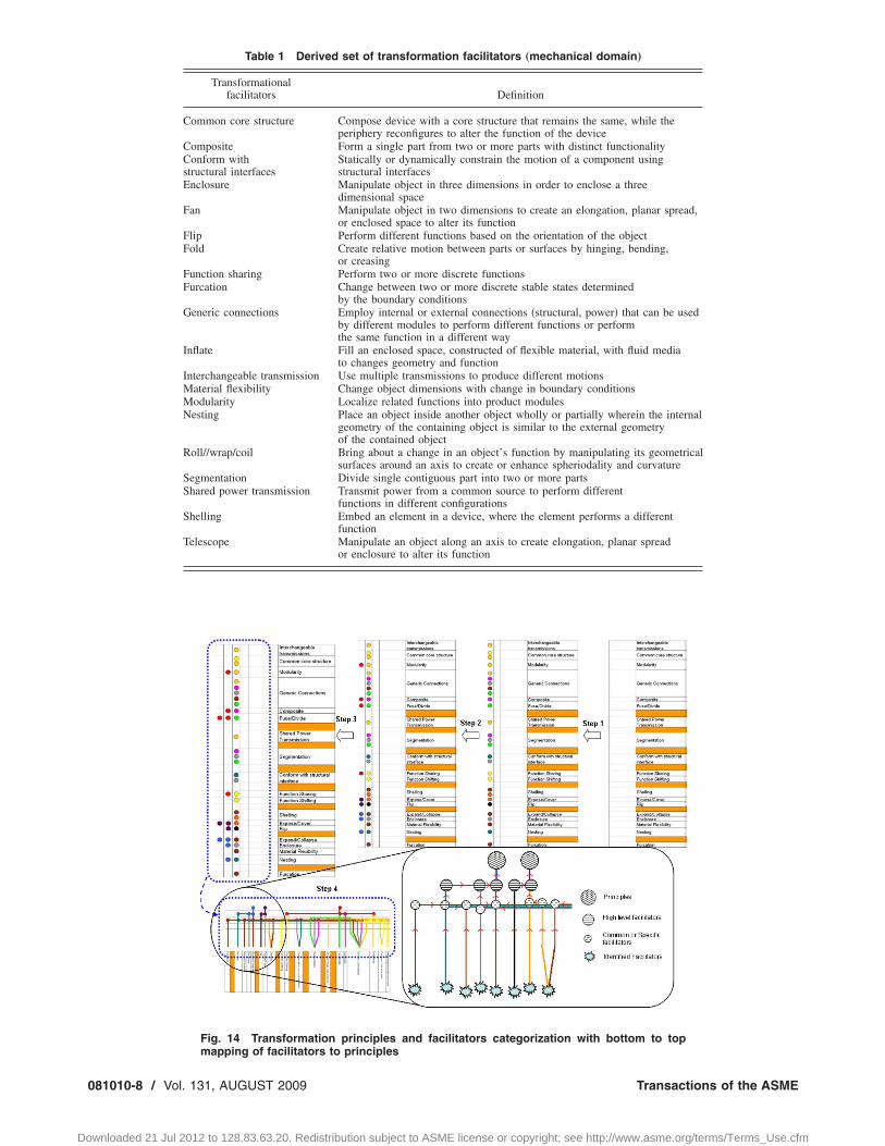
3.3 Transformation Principles and FacilitatorsCategorization. Table 1 shows a list of transformation facilitatorsdeveloped from the combined inductive and deductive ap-proaches. To determine transformation principles from this list,the transformation facilitators are studied and grouped. Thesetransformation facilitators will be described more fully in Sec. 4below. However, Table 1 provides an overview of the transforma-tion facilitators as they are the antecedents for developing thetransformation principles. The steps involved in the process ofusing the transformation facilitators to develop the transformationprinciples are described and graphically depicted in Fig. 14, wherea description of each step is as follows.
• Step 1. The facilitators are grouped on the basis of identify-ing major elements and key features of the existing and/orhypothesized product at a systems level, and/or parts level.These are facilitators that repeatedly appear together andintegrally support the transformation within a system be-tween the product’s primary states. For example, inter-changeable transmissions, common core structure, modular-
Fig. 11 Search methodology for patented devices which showtransformation
ity, generic connections, and shared power transmission are
Transactions of the ASME
license or copyright; see http://www.asme.org/terms/Terms_Use.cfm

J
Do
grouped together based on the frequency of their use in sys-tems that innovatively transform according to “fusing” and“dividing.”
• Step 2. To create a visual representation, the facilitators thatare grouped are color coded; each group of facilitators beingassigned a different color. This process of tagging groupswith a common color helps to iterate the formation of thesegroups and identify that these groups of facilitators couldcross the initial raw distinctions by either including commonfacilitators or incorporating another group of facilitators as asub group. For example, generic connections is found inmany groups as a common facilitator; common core struc-
Fig. 12 Product search methodology
Fig. 13 Deductive research approach
ournal of Mechanical Design
wnloaded 21 Jul 2012 to 128.83.63.20. Redistribution subject to ASME
ture is also found to be common facilitator for modularityand function sharing-function shift �function shift is associ-ated under function sharing�, and furcation is identified as afacilitator grouped only under expand/collapse �56,57�.
• Step 3. The next step is to identify super groups, if any, tothese facilitator sub groups. A different color is tagged nextto the facilitator that fully captured the common functional-ity, interaction, and physical states as described by the trans-formation facilitators. For example, this process results in asuper group involving modularity, composite, and functionsharing.
• Step 4. With higher level facilitators, such as modularity,composite, and function sharing being embodied by fuse/divide, this process results in all the transformation facilita-tors in the mechanical domain being categorized by threefundamental transformation principles: “expand/collapse,”“expose/cover,” and “fuse/divide.” Fig. 14 shows the map-ping of the transforming facilitators leading to transforma-tion principles, from bottom to top. In addition the catego-rization process described above helped to consolidatefacilitators like function sharing and function shifting intoone facilitator—function sharing. It also helped layout a net-work of facilitators which aided certain principles, some ofwhich were found to be aided by more than one facilitator.Inductive and deductive reasoning was further carried out torefine the list of facilitators by adding to the already descrip-tive list of facilitators found through the initial study. Thiswas done to make these transformational design guidelinesmore direct and distinct.
4 Definitions and Principle DescriptionBased on the facilitator extraction process, we arrive at the
following formal definitions:
4.1 Transformation Principle. A transformation principle isa generalized directive to bring about a certain type of mechanicaltransformation. A transformation principle is a guideline that,when embodied, singly creates a transformation.
4.2 Transformation Facilitators. A transformation facilitatoris a design construct that helps or aids in creating mechanicaltransformation. Transformation facilitators aid in the design fortransformation, but their implementation does not create transfor-mation singly.
4.3 Transformation Principles. For consistency, a commonform of writing the principles and facilitators is desired. The de-velopment of a common lexicon is needed to achieve an equiva-lent semantic level for each principle and facilitator. The lexiconis similar to the design principles stated in the theory of inventiveproblem solving �TIPS or TRIZ�, developed by Genrikh S. Alt-shuller in the former USSR, beginning in the late 1940s 58–61, inthe principles described for effort flow analysis �62,63�, or in prin-ciples developed for product flexibility �64,65�.
Through our research approach, as described in the four stepprocess of Fig. 14, we have found that there are three fundamentaltransformation principles, expand/collapse, expose/cover, andfuse/divide, which fully represent transformation potential in themechanical domain. Subordinate to these three principles, thereare transformation facilitators. The hierarchical relationship be-tween principle and facilitator exists because principles describewhat causes transformation, while facilitators describe whatmakes the transformation function fully and efficiently.
Based on this development, we now consider the meaning ofthe principles, with suitable examples from the data sources ofproduct systems, natural analogies, and patents.
• Transformational Principle No. 1: expand/collapse. Changephysical dimensions of an object to bring about an increase/decrease in occupied volume primarily along an axis, in a
plane or in three dimensions. Collapsible or deployableAUGUST 2009, Vol. 131 / 081010-7
license or copyright; see http://www.asme.org/terms/Terms_Use.cfm
0
Do
Table 1 Derived set of transformation facilitators „mechanical domain…
Transformationalfacilitators Definition
Common core structure Compose device with a core structure that remains the same, while theperiphery reconfigures to alter the function of the device
Composite Form a single part from two or more parts with distinct functionalityConform withstructural interfaces
Statically or dynamically constrain the motion of a component usingstructural interfaces
Enclosure Manipulate object in three dimensions in order to enclose a threedimensional space
Fan Manipulate object in two dimensions to create an elongation, planar spread,or enclosed space to alter its function
Flip Perform different functions based on the orientation of the objectFold Create relative motion between parts or surfaces by hinging, bending,
or creasingFunction sharing Perform two or more discrete functionsFurcation Change between two or more discrete stable states determined
by the boundary conditionsGeneric connections Employ internal or external connections �structural, power� that can be used
by different modules to perform different functions or performthe same function in a different way
Inflate Fill an enclosed space, constructed of flexible material, with fluid mediato changes geometry and function
Interchangeable transmission Use multiple transmissions to produce different motionsMaterial flexibility Change object dimensions with change in boundary conditionsModularity Localize related functions into product modulesNesting Place an object inside another object wholly or partially wherein the internal
geometry of the containing object is similar to the external geometryof the contained object
Roll//wrap/coil Bring about a change in an object’s function by manipulating its geometricalsurfaces around an axis to create or enhance spheriodality and curvature
Segmentation Divide single contiguous part into two or more partsShared power transmission Transmit power from a common source to perform different
functions in different configurationsShelling Embed an element in a device, where the element performs a different
functionTelescope Manipulate an object along an axis to create elongation, planar spread
or enclosure to alter its function
Fig. 14 Transformation principles and facilitators categorization with bottom to top
mapping of facilitators to principles81010-8 / Vol. 131, AUGUST 2009 Transactions of the ASME
wnloaded 21 Jul 2012 to 128.83.63.20. Redistribution subject to ASME license or copyright; see http://www.asme.org/terms/Terms_Use.cfm

J
Do
structures are capable of automatically �or through mechani-cal actuation� varying their shape from a compact, packagedconfiguration to an expanded, operational configuration. InFig. 15�a�, the portable sports chair expands for sitting andcollapses for storage or portability; in Fig. 15�b�, the pufferfish expands its body to ward off predators; and in Fig.15�c�, the bag in this patent expands from a towel to a totebag configuration.
• Transformational Principle No. 2: expose/cover. Reveal orconceal a new surface to alter functionality. This principle isa directive for changing the surface of a device or its partsso as to alter the primary function of the device. This alter-ation can be brought about by a part-to-part interaction ofthe device and/or the overall form of the device itself. InFig. 16�a�, the chair rotates and exposes new surfaces tobecome a step ladder; in Fig. 16�b�, the Day-blooming waterlily opens during the day to expose its interior, and closes atnight; and in Fig. 16�c�, the keyboard in this patent folds outto reveal the operational surface.
• Transformational Principle No. 3: fuse/divide. Make asingle functional device become two or more devices �dis-cretization�, at least one of which has its own distinct func-tionality defined by the state of the transformer, or viceversa. Two or more parts with distinct or similar primaryfunctions can fuse/join to form a new device. In Fig. 17�a�,the product shown is an audio player, which also functionsas a USB flash drive or a memory stick. It connects to apower source module making the audio player portable; inFig. 17�b�, Army ants join their bodies to form a bridge forthe rest of the colony; and in Fig. 17�c�, the patented deviceshown has divisible or segmented parts that function as aplatform in one configuration, or function as alternative ex-ercise device in another configuration.
Fig. 15 Examples “expand/collapse” †12,66,67‡
Fig. 16 Examples “expose” †11,68,69‡
Fig. 17 Examples “fuse/divide” †70–72‡
ournal of Mechanical Design
wnloaded 21 Jul 2012 to 128.83.63.20. Redistribution subject to ASME
4.4 Transformation Facilitators. Transformation facilitatorsassist in the design of transformers, i.e., they enable transforma-tion functionality. While singly embodying a transformation prin-ciple can create a transforming product, transformation facilitatorsdo not create transformation alone.
Based on the inductive and deductive research approaches, thetransformation facilitators developed in this research include thefollowing.
• Common core structure—compose device with a core struc-ture that remains the same, while the periphery reconfiguresto alter the function of the device. In essence, a reconfig-urable device can consist of a core structure that is the mainsupport structure that allows for aligning/positioning differ-ent peripheral parts or systems. In Fig. 18�a�, the leaf blow-er’s working organ remains the same, while the usableimplements change the device operation from a blower to avacuum; in Fig. 18�b�, the reproductive termite begins lifeas a crawling insect, then grows wings to leave the colony,and sheds its wings to take the roll of a queen of a newcolony; and in Fig. 18�c�, the cane system changes function-ality depending on its attachments.
• Composite—form a single part from two or more parts withdistinct functionality. Here the parts that form the compositestructure do not functional individually, but become func-tional when arranged together. In Fig. 19�a�, LEGO® partsshown in the drive system consist primarily of a set ofsplined shafts �black� and mounted gears �gray�. The indi-vidual gears and the splined shafts alone do not perform thefunction of transmitting power; in Fig. 19�b�, DNA changesits function based on the specific sequencing of nucleotides;and in Fig. 19�c�, the shapes of the blunt edges of a utilityknife, in this patent, forms a handle out of its cutting utensilswhen they are not in use.
• Conform with structural interfaces—statically or dynami-cally constrain the motion of a component using structuralinterfaces. Parts or devices structurally conform with otherparts or devices to aid in the transformation of the part ordevice to produce distinct functionality. In Fig. 20�a�, flipphones maintain their open position by constraining the mo-
Fig. 18 Examples “common core structure” †3,73,74‡
Fig. 19 Examples “composite” †75–77‡
AUGUST 2009, Vol. 131 / 081010-9
license or copyright; see http://www.asme.org/terms/Terms_Use.cfm

F
0
Do
tion of the headset section against a structural interface onthe base; in Fig. 20�b�, the kangaroo uses its tail as a struc-tural member that interfaces with the terrain to provide moresupport while standing; and in Fig. 20�c�, the patented con-tainer uses self-locking structural interfaces to define its fi-nal shape.
• Enclosure—manipulate object in three dimensions in orderto enclose a three dimensional space. Alteration in an ob-ject’s functionality can be brought about by manipulating itsgeometric configuration in space. For example, Fig. 21�a�,describing this facilitator is a flat cardboard cut out which isfolded and creased to enclose space and store objects insideit; in Fig. 21�b�, an octopus can manipulate its flexible bodyand tentacles to enclose a large space to appear bigger andward off its predators; and in Fig. 21�c�, the patent showshow a flat layout of this object can be changed in threedimensions to enclose a volume and function to store some-thing, in this case, act as a cup or a small bowl.
• Fan—manipulate object in two dimensions to create anelongation, planar spread, or enclose space to alter its func-tion. This can be the transition of a two dimensional move-ment into a one, two or three dimensional expansion. Figure22�a� shows a hand fan which fans out to enclose a volume,and thus transforms into a hat for providing shade; in Fig.22�b�, the frilled lizard fans out its large thin frill around itsneck to intimidate its enemies by appearing larger; and inFig. 22�c�, the patent shows an apparatus for increase ofaircraft lift and maneuverability. The patent claims the wingon an aerofoil composed of two separate halves, the top half�first� and the bottom half �second� split along the chord ofthe wing. The first and second aerofoils are connected to thefuselage at the root, where a mechanism pivots the secondaerofoil about the first. This increases the aircraft lift andmaneuverability making the aircraft more agile.
• Flip—perform different functions based on the orientation ofthe object. This facilitator implies re-orienting an object,
ig. 20 Examples “conform with structural interfaces” †78–80‡
Fig. 21 Examples “enclosure” †80–82‡
81010-10 / Vol. 131, AUGUST 2009
wnloaded 21 Jul 2012 to 128.83.63.20. Redistribution subject to ASME
where the object now has a different interacting surface tofacilitate a distinct functionality. In Fig. 23�a�, the hand heldlight is flipped to expose its solar cell array and interfacewith the handle; in Fig. 23�b�, an otter’s belly, when floatingupside down, functions as a horizontal support surface forcarrying young or preparing food; and in Fig. 23�c�, thepatent shown functions as a stapler on one end, and whenflipped upside down the opposite end functions as a holepunch.
• Fold—create relative motion between parts or surfaces byhinging, bending, or creasing. This relative motion recon-figures the geometric layout of a part�s� in the object facili-tating a change in the objects energy, material, or signal flowinteraction. Figure 24�a� shows the �conceptual� transitioncar, which has wings folded toward its body where thewings can unfold to generate enough lift to transition the carinto a small aircraft; in Fig. 24�b�, birds fold their wingswhen perched on a branch, to roam the landscape for foodand to change speeds suiting their needs during flight; and inFig. 24�c�, the patented hand bag unfolds to become a sleep-ing bag, and one side of this sleeping bag encloses a volumewhich can be accessed in the hand bag configuration to storeobjects.
• Function sharing—perform two or more discrete functions.The transforming device consists of parts that have two ormore functions defined by the state of the transforming de-vice, or throughout the state of the transforming device. Inessence the part is multifunctional in a configuration �func-tion sharing� or a part of the device performs a primaryfunction in one configuration, but performs a different pri-mary function in another state of the device �function shift-ing�. In Fig. 25�a�, the rims of the rear wheels of this am-phibious toy car become propellers in an alternativeconfiguration of the wheels; in Fig. 25�b�, while resting, thepattern on this butterfly’s wings mimics the eyes of a larger
Fig. 22 Examples “fan” †56,83,84‡
Fig. 23 Examples “flip” †77,85,86‡
Fig. 24 Examples “fold” †87–89‡
Transactions of the ASME
license or copyright; see http://www.asme.org/terms/Terms_Use.cfm

J
Do
animal to ward off potential predators; and in Fig. 25�c�, thedumbbells of this patented exercise equipment function aslegs in an alternative configuration, an example of functionshifting.
• Furcation—change between two or more discrete stablestates determined by the boundary conditions. A transform-ing product is designed with multiple stable states, and thetransition between these states is defined by a set of bound-ary conditions imposed upon it. In Fig. 26�a�, the commonslap bracelet toy is an example of a bistable structure that isstable in its extension state until part of its cross-section isflattened, at which time it collapses to a lower-energy coiledstate; in Fig. 26�b�, a Venus fly trap snaps its leaves shut inabout one-tenth of a second, by reversing the curvature of itsleaves releasing stored energy; and in Fig. 26�c�, this um-brella is a bifurcating device with two stable states—openand closed.
• Generic connections—employ internal or external connec-tions (structural, power) that can be used by different mod-ules to perform different functions or perform the same func-tion in a different way. Basic common interconnectionsbetween parts of a device or between devices facilitate thetransformation of a device or a system having a distinctfunctionality. In Fig. 27�a�, the poles and connecters in thisproduct form different structures using quick connections; inFig. 27�b�, identical synaptic connections between two braincells can result in different end effects, depending on thedifferent connection configurations; and in Fig. 27�c�, the
Fig. 25 Examples “function sharing” †90–92‡
Fig. 26 Examples “furcation” †93–95‡
Fig. 27 Examples “generic connections” †96–98‡
ournal of Mechanical Design
wnloaded 21 Jul 2012 to 128.83.63.20. Redistribution subject to ASME
bars and nodes of this patent can be reconfigured for a va-riety of structures.
• Inflate—fill an enclosed space, constructed by flexible mate-rial, with fluid media to alter function. Functionality changeis brought about by replacing solid components in a devicewith flexible materials enclosing a volume. Fluid �liquidand/or gas� is then used to inflate these components to bringabout a change in the geometry thereby facilitating a changein functionality. Figure 28�a� shows the inflatable antennaexperiment �IAE� deployed in space. The noninflatable ver-sion of this antenna would have taken a prohibitive amountof cargo space in the space shuttle. In Fig. 28�b� the pufferfish inflates its body to appear larger and stiffen the spikeson its body to ward off and escape predators; and in Fig.28�c�, the patented chair has an outer chamber that definesthe shape and size of the chair, and is constructed of anenclosed compliant membrane which when inflated createsthe specific shape and size of a chair.
• Interchangeable transmission—use different transmissionsto produce different motions. Transformation in motion orany form of flow �energy, material, and signal� related totransformation can be facilitated by changing the means oftransmission associated with the original motion. Figure29�a�, Black and Decker’s multitool has one central motorwhich is housed inside the body/handle housing where theattachments, sander, drill, and jig saw, have different trans-mission to produce different types of motion �with respect tothe work piece� as would be required for sanding, sawing ordrilling; In Fig. 29�b�, the front transmission changes from awheel to a ski to produce a rotating motion and a slidingmotion, respectively, both of which are suitable to accom-plish travel under different terrain conditions; and in Fig.29�c�, the patented bicycle’s transmission is interchangeablefrom its normal transmission to a transmission with a pro-peller, similar to that of a small boat. In this second configu-ration there are float attachments that take the place of thefront and rear tires of the bike.
• Material flexibility—change object dimensions with changein boundary conditions. Replacing the surface or structureof an object by a flexible membrane or film gives a potentialfor it to stretch in length or area depending on the direction
Fig. 28 Examples “inflate” †14,99,100‡
Fig. 29 Examples “interchangeable transmission” †2,101,102‡
AUGUST 2009, Vol. 131 / 081010-11
license or copyright; see http://www.asme.org/terms/Terms_Use.cfm
0
Do
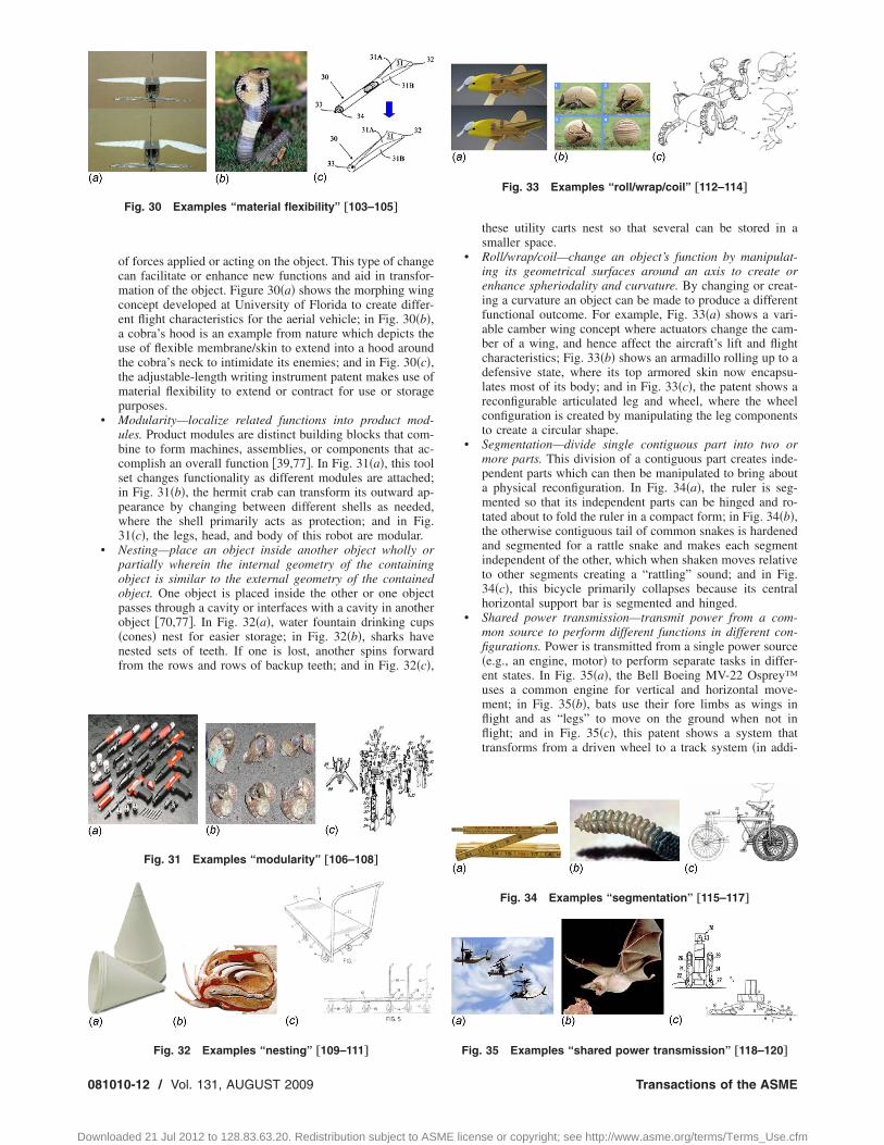
of forces applied or acting on the object. This type of changecan facilitate or enhance new functions and aid in transfor-mation of the object. Figure 30�a� shows the morphing wingconcept developed at University of Florida to create differ-ent flight characteristics for the aerial vehicle; in Fig. 30�b�,a cobra’s hood is an example from nature which depicts theuse of flexible membrane/skin to extend into a hood aroundthe cobra’s neck to intimidate its enemies; and in Fig. 30�c�,the adjustable-length writing instrument patent makes use ofmaterial flexibility to extend or contract for use or storagepurposes.
• Modularity—localize related functions into product mod-ules. Product modules are distinct building blocks that com-bine to form machines, assemblies, or components that ac-complish an overall function �39,77�. In Fig. 31�a�, this toolset changes functionality as different modules are attached;in Fig. 31�b�, the hermit crab can transform its outward ap-pearance by changing between different shells as needed,where the shell primarily acts as protection; and in Fig.31�c�, the legs, head, and body of this robot are modular.
• Nesting—place an object inside another object wholly orpartially wherein the internal geometry of the containingobject is similar to the external geometry of the containedobject. One object is placed inside the other or one objectpasses through a cavity or interfaces with a cavity in anotherobject �70,77�. In Fig. 32�a�, water fountain drinking cups�cones� nest for easier storage; in Fig. 32�b�, sharks havenested sets of teeth. If one is lost, another spins forwardfrom the rows and rows of backup teeth; and in Fig. 32�c�,
Fig. 30 Examples “material flexibility” †103–105‡
Fig. 31 Examples “modularity” †106–108‡
Fig. 32 Examples “nesting” †109–111‡
81010-12 / Vol. 131, AUGUST 2009
wnloaded 21 Jul 2012 to 128.83.63.20. Redistribution subject to ASME
these utility carts nest so that several can be stored in asmaller space.
• Roll/wrap/coil—change an object’s function by manipulat-ing its geometrical surfaces around an axis to create orenhance spheriodality and curvature. By changing or creat-ing a curvature an object can be made to produce a differentfunctional outcome. For example, Fig. 33�a� shows a vari-able camber wing concept where actuators change the cam-ber of a wing, and hence affect the aircraft’s lift and flightcharacteristics; Fig. 33�b� shows an armadillo rolling up to adefensive state, where its top armored skin now encapsu-lates most of its body; and in Fig. 33�c�, the patent shows areconfigurable articulated leg and wheel, where the wheelconfiguration is created by manipulating the leg componentsto create a circular shape.
• Segmentation—divide single contiguous part into two ormore parts. This division of a contiguous part creates inde-pendent parts which can then be manipulated to bring abouta physical reconfiguration. In Fig. 34�a�, the ruler is seg-mented so that its independent parts can be hinged and ro-tated about to fold the ruler in a compact form; in Fig. 34�b�,the otherwise contiguous tail of common snakes is hardenedand segmented for a rattle snake and makes each segmentindependent of the other, which when shaken moves relativeto other segments creating a “rattling” sound; and in Fig.34�c�, this bicycle primarily collapses because its centralhorizontal support bar is segmented and hinged.
• Shared power transmission—transmit power from a com-mon source to perform different functions in different con-figurations. Power is transmitted from a single power source�e.g., an engine, motor� to perform separate tasks in differ-ent states. In Fig. 35�a�, the Bell Boeing MV-22 Osprey™uses a common engine for vertical and horizontal move-ment; in Fig. 35�b�, bats use their fore limbs as wings inflight and as “legs” to move on the ground when not inflight; and in Fig. 35�c�, this patent shows a system thattransforms from a driven wheel to a track system �in addi-
Fig. 33 Examples “roll/wrap/coil” †112–114‡
Fig. 34 Examples “segmentation” †115–117‡
Fig. 35 Examples “shared power transmission” †118–120‡
Transactions of the ASME
license or copyright; see http://www.asme.org/terms/Terms_Use.cfm

5
Fdcflhtpasid
p
J
Do
tion to a secondary function of acting as a suspension�.• Shelling—embed an element in a device, where the element
performs a different function. Shell or cover a component orpart�s� of a component inside itself, with or within anothercomponent. In Fig. 36�a�, a blade is embedded within theshaft of the cane; in Fig. 36�b�, turtles hide within their hardshells to protect themselves from predators; and in Fig.36�c�, the patent shows a modular instrument that hides itsinterchangeable heads within its body.
• Telescope—manipulate an object along an axis to create anelongation, planar spread, or enclosure to alter its function.By moving the components of an object along one particulardirection creating a longitudinal stretch, spread, or just toenclose a volume can change the objects functionality. Fig-ure 37�a� shows bellow shaft couplings which can be ex-tended to a variety of desired lengths to couple shafts sepa-rated by varying distances; Figure 37�b� shows a seaanemone which telescopes out to reveal its tentacles in orderto catch planktons to feed itself; and Fig. 37�c� shows apatent on a telescoping writing instrument, which has ad-justable length for comfortable writing when extended andis collapsed for portability.
Research ResultsThe primary results of the research include the following:
• a set of transformation principles and facilitators �mechani-cal domain�, forming the foundation of a transformationaldesign theory
• validation of this set• application of the principles and facilitators
5.1 Set of Transformation Design Principles andacilitators. The transformation design principles and facilitatorsocumented in Sec. 4 are heuristic rules, which create high leveloncepts that indicate inventive solutions for designing a trans-orming product. These concepts form categories of possible so-utions to a transformational design problem. The principles areigh-level functional solutions, i.e., meta-analogies, and the facili-ators are catalysts that may be used singularly or through super-osition to assist or enable transformations. The set of facilitatorslso represent a wide range of possible form solutions. Table 2ummarizes the transformational principles and facilitators, creat-ng the foundation of a transformational design theory from whichesign methods may be developed.
5.2 Validation. It is necessary to determine what number ofroducts, patents and natural analogies is sufficient to capture the
Fig. 36 Examples “shelling” †121–124‡
Fig. 37 Examples “telescope” †125–127‡
ournal of Mechanical Design
wnloaded 21 Jul 2012 to 128.83.63.20. Redistribution subject to ASME
overwhelming majority of transformation design principles andfacilitators. To determine, at least in part, this sufficiency condi-tion, data is compiled for the number of distinct principles thateach product, patent, and natural analogy revealed.
We present the sufficiency condition for patents in Fig. 38,where here again the focus is on the mechanical domain. Aftersearching tens-of-thousands of patents with our search approach,hundreds of patents were extracted. These extracted patents exhib-ited rich transformer descriptions, and were then studied in greatdetail. Figure 38 plots two curves as the subset of the patents thatwere studied, one curve displays the number of new facilitators orpotential principles that each patent exposed, and the other tracksthe cumulative total of principles and facilitators. These two plotsare superimposed on the same chart.
The plots clearly show that the majority of principles are ex-tracted in the first half of patents analyzed. Analysis of the firstfive patents alone yielded 18 of the 23 transformation principlesand facilitators �a verification of the search procedure developedfor patents�. If this trend holds true in general, it can be assumedthat while it is very possible that not all principles were discov-ered with an analysis of only 41 extracted patents, a high percent-age of them were. A similar validation may be generated for natu-ral analogies and product systems. This validation is a continuingprocess, where at the limit with a large repertoire of products,patents, and natural analogies, the number of principles/facilitators flattens �or becomes asymptotic� versus the number ofpatents/products/natural analogies analyzed.
5.3 Application in Design for Transformation. Using thenewly developed set of transformation principles and facilitatorsas a foundation, a mind mapping approach �60� is used to developa list of possible transformation products. The mind map includesthe need for new transformation products at the center, wherecategories of solutions are labeled as the principles and facilita-tors. The transformation design principles and facilitators led tothe development of the list shown below:
• water rocket ←→ squirt gun• raincoat ←→ umbrella• hose sprayer ←→ lawn/garden sprinkler• fishing rod handle ←→ rod stand• toaster ←→ electric griddle ←→ cooking top• dress shoes ←→ golf shoes• water-sensitive roof shingles converting to gutters• skis ←→ snowboard• hairdryer ←→ curling iron ←→ hair straightener• headphones → speaker• cooler ←→ picnic table• motorcycle ←→ all terrain vehicle
This list of potential new transformer products is partial andintended to be illustrative. Such a list provides insights into trans-former ideas that can be developed through the understanding ofthe transformational design theory based on the knowledge of theprinciples and facilitators.
An idea, from the transformer product list and which the re-search team found to have an attractive application, consists of amotorcycle that transforms into an all terrain vehicle �ATV�. Fig-ure 39 helps to illustrate the need for such a transformer. Figure40 shows the Mind Map that aids in the concept generation ofmotorcycle/ATV transforming designs.
A motorcycle is more maneuverable, aerodynamic, and smallerthan an ATV, but is unfit for all terrains, less stable at low speeds,not suited for reverse motion and transports less material as op-posed to an ATV. For example a motorcycle would be unfit forslowly crawling on rough terrain as it is balanced by only twowheels, but it is required when the need is for maneuverability andsmaller occupied space. A transformer may satisfy the combined
needs and functionality of a motorcycle and an ATV. We used ourAUGUST 2009, Vol. 131 / 081010-13
license or copyright; see http://www.asme.org/terms/Terms_Use.cfm

ttcc
cst�l
P
F
0
Do
heory of transformation to develop a concept of a transformerhat transforms from a two wheel configuration into a four wheelonfiguration. Figure 41 shows an initial embodiment of thisoncept.
The design process started with identifying the most complexommon sub assemblies, for example the wheels. The states of theub assemblies were studied, and principles were applied to createransformation between the states. For example transformationFigs. 42–44� from a motorcycle to an ATV incorporates the fol-owing transformation principles and facilitators.
• Each wheel divides into two wheels: fuse/divide.• The body shell and structure are made of different parts with
a collapsing structure that facilitates the operation of trans-forming from the motorcycle to the all terrain vehicle body:expand/collapse with fuse/divide, conform with structuralinterface.
• The common suspension structure of each wheel splits intofour independent suspension structures for the four wheels:
Table 2 Transformation design princi
Principle/Facilitator
rinciples
Expand/Collapse
Expose/CoverFuse/Divide
acilitators
Common Core Structure
CompositeConform with structural interfaces
Enclosure
Fan
FlipFold
Function sharingFurcation
Generic connections
Inflate
Interchangeable transmissionMaterial flexibilityModularityNesting
Rolf/wrap/coil
Seamen rationShared power transmission
Shelling
Telescope
fuse/divide; function sharing.
81010-14 / Vol. 131, AUGUST 2009
wnloaded 21 Jul 2012 to 128.83.63.20. Redistribution subject to ASME
The core of the motorcycle �engine, seat, and steering� remainsthe same, while transforming into an ATV: common core structureand shared power transmission.
The transformer �motorcycle/ATV� is a preliminary conceptembodying transformation principles and transformation facilita-tors. Current evolution of the device demonstrates the utility ofthe transformation design theory. Figures 44�a� and 44�b� show a1:9 scaled down model of the motorcycle-ATV concept. An ex-panding and collapsing frame essentially changes the two wheelconfiguration to a four wheel configuration. This expanding andcollapsing mechanism is essentially a scissor joint moved by oneor two actuators. The power sources for transformation in thescaled prototype are two servo motors, one actuates the mecha-nism transforming the front wheel of the motorcycle into the fronttwo wheels of the ATV configuration. Similarly, the second servomotor actuates the mechanism transforming the rear wheel intotwo rear wheels for the ATV configuration.
To drive the motorcycle-ATV the engine or power source can
s and facilitators with their definitions
Definition
Change physical dimensions of an object to bring about an increasedecrease in occupied volume primarily along an axis, in a plane, or inthree dimensionsReveal or conceal a new surface to alter functionalityMake a single functional device become two or more devices�discretization�,at least one of which has its own distinct functionality defined by thestate ofthe transformer, or vice versa
Compose device with a core structure that remains the same, while theperiphery reconfigures to alter the function of the deviceForm a single part from two or more parts with distinct functionalityStatically or dynamically constrain the motion of a component usingstructural interfacesManipulate object in three dimensions in order to enclose a threedimensional spaceManipulate object in two dimensions to create an elongation, planarspread, or enclosed space to alter its functionPerform different functions based on the orientation of the objectCreate relative motion between parts or surfaces by hinging, bending,or creasingPerform two or more discrete functionsChange between two or more discrete stable states determined by theboundary conditionsEmploy internal or external connections �structural, power� that can beused by different modules to perform different functions or perform thesamefunction in a different wayFill an enclosed space, constructed of flexible material, with fluidmedia to changes geometry and functionUse multiple transmissions to produce different motionsChange object dimensions with change in boundary conditionsLocalize related functions into product modulesPlace an object inside another object wholly or partially wherein theinternal geometry of the containing object is similar to the externalgeometryof the contained objectBring about a change in an object’s function by manipulating itsgeometrical surfaces around an axis to create or enhance spheriodalityand curvatureDivide single contiguous part into two or more partsTransmit power from a common source to perform different functionsin different configurationsEmbed an element in a device, where the element performs a differentfunctionManipulate an object along an axis to create elongation planar spread,or enclosure to alter its function
ple
be directly fitted on the wheel, therefore eliminating some com-
Transactions of the ASME
license or copyright; see http://www.asme.org/terms/Terms_Use.cfm

Fpatents analyzed
Fig. 40 Mind map for motorcycle/ATV transforming designs
Journal of Mechanical Design
Downloaded 21 Jul 2012 to 128.83.63.20. Redistribution subject to ASME
plexity in the design by not having to include a propeller shaft,axel, or other power transmission device. Current technology canaccomplish this function. For example, RevoPower™ �130� �Fig.45�a�� has developed a wheel based two stroke internal combus-tion engine which is thin enough wherein the engine can spinbetween the forks of a standard bicycle. Also Honda has success-fully manufactured its moped, Honda City Express �131�, with apancake motor fitted directly adjacent to the wheel �Fig. 44�b��.The Michelin E.A.P tire system, designed by James Owen �132�,is a revolutionary design further enabling the feasibility of trans-formation in this product to bring about change in the overallfunction of the device. Figure 46 shows the four forms the tire canmorph into. The concept of a morphing tire is to change the tire
Fig. 41 Concept sketch of a motorcycle-ATV Transformer
Fig. 42 Motorcycle configuration
ig. 38 Number of principles/facilitators versus number of
Fig. 39 Comparison of a motorcycle and an ATV †128,129‡
Fig. 43 ATV configuration
AUGUST 2009, Vol. 131 / 081010-15
license or copyright; see http://www.asme.org/terms/Terms_Use.cfm

Fcycle configuration and „b… ATV configuration
FH
F†132‡
081010-16 / Vol. 131, AUGUST 2009
Downloaded 21 Jul 2012 to 128.83.63.20. Redistribution subject to ASME
surface topology to suit the traction requirements of the wheel indry, low rolling resistance, wet, and snow conditions. These aresome solutions which may bring this transformer concept into aworking reality.
6 Conclusion and Future WorkThe devices that transform capture one’s imagination. They en-
thuse and peak our curiosity, much like the childhood “Trans-former” cartoons and toys �1,87,133�. They perform multiple tasksand functionality beyond the single focus of most products. Theyexpand the envelope of creative and innovative thought. Theyseek to delight, efficiently and effectively, customers in ways thatare unforeseen or forecasted. However, no foundation exists, be-yond experiential approaches and serendipity, for understandinghow to design and develop transformers. This paper utilizes acombined inductive and deductive research methodology for ex-ploring transformation and developing a theoretical basis.
The results from this methodology are exciting. Three funda-mental principles and a number of critical facilitators are pre-sented and illustrated. These principles and facilitators form abudding theory of transformation in design. Initial results ofimplementing this theory, for example in unmanned aerial vehicle�UAV� technology �134,135�, the motorcycle-ATV transformerand the generation of novel transformer concepts, are a clear in-dicator of their potential in product development and beyond. Thisresearch has tremendous potential to change contemporary engi-neering design �136� culture and provides a basis for the develop-ment of innovation processes and methods.
AcknowledgmentThe authors would like to acknowledge the support provided by
the Cullen Endowed Professorship in Engineering, The Universityof Texas at Austin, and grants from the Air Force Research Labo-ratory Munitions Directorate �AFRL/RW� at Eglin, FL and the AirForce Office of Scientific Research �AFOSR�. The authors wouldalso like to thank the Department of Engineering Mechanics at theU.S. Air Force Academy for their support and guidance.
References�1� 2005, Transformer Toys, http://www.hasbro.com/.�2� 2005, Black and Decker 14.4V Cordless Quattro Multi-Tool With Kit Box,
http://www.lenehans.ie/lenehans/Images/DB_Detail/kc2002fk.jpg.�3� 2005, Blower and Vacuum, http://www.ebigchina.com/ebcps/4/pd/
888604.html.�4� 2005, Kitchen Step Stool Chair, http://www.asseenontv.com/prod-pages/
wood_step_ladder.html?gid.�5� 2006, Milwaukee’s 6016–6 ¼ Sheet Orbital Palm Sander, http://
www.tylertool.com/mi6014shorpa.html.�6� 2005, Panasonic MC-E7103, http://www.beststuff.co.uk/
cylinder_vacuum_cleaners.htm.�7� 2005, Poulan Weed Eater 7.5-amp Electric Leaf Blower, http://
www.walmart.com/catalog/product.gsp?product_id�876348.�8� Drill, P., 2005, http://www.am-wood.com/images/tools/drill.gif.�9� 2005, Ryobi Jso45 Variable Speed Orbital Action Jig Saw, www.epinions.com.
�10� 2005, Solid Wood Furniture by WoodCiti® Furniture Thailand, http://www.thailandtradenet.com/photos/catalog/chair/wooden-chair.jpg.
�11� 2005, Two-Foot Stepping Ladder, http://loopy.cc/pt_stools.php.�12� 2005, The Brute B-2 Folding Chairhttp://www.buyersbox.com/
deluxe_folding_chairs.html.�13� European Patent Office Website, http://ep.espacenet.com.�14� Freeland, R. E., Bilyeu, G. D., Veal, G. R., Steiner M. D., and Carson D. E.,
1997, “Large Inflatable Deployable Antenna Flight Experiment Results,” In-ternational Astronautical Federation.
�15� 2005, New Tricycle Morphs Into Bike on the Go, http://www.livescience.com/technology/050429_bike_trainer.html.
�16� Robbin, T., 1996, Engineering a New Architecture, Quebeco-Eusey, Leomin-ster, MA.
�17� U.S. Patent and Trademark Office Website, http://www.upto.gov.�18� Siddiqi, A., and Weck, O.L., 2008, “Modeling Methods and Conceptual De-
sign Principles for Reconfigurable Systems,” ASME J. Mech. Des., 130�10�,p. 101102.
�19� Khire, R. A., and Messac, A., 2008, “Selection-Integrated Optimization �SIO�Methodology for Optimal Design of Adaptive Systems,” ASME J. Mech. Des.,130�10�, p. 101401.
�20� Collier, D. A., 1981, “The Measurement and Operating Benefits of Component
ig. 44 Motorcycle-ATV Transformer “Morphix” „a… motor-
ig. 45 „a… RevoPower™ two-stroke I.C engine †130‡ and „b…onda City Express pancake motor moped †131‡
ig. 46 Morphing tires: „a… wet condition and „b… dry condition
Part Commonality,” Decision. Sci., 12�1�, pp. 85–96.Transactions of the ASME
license or copyright; see http://www.asme.org/terms/Terms_Use.cfm

J
Do
�21� Kota, S., Sethuraman, K., and Miller, R., 2000, “A Metric for EvaluatingDesign Commonality in Product Families,” J. Mech. Des., 122�4�, pp. 403–410.
�22� McDermott, C. M., and Stock, G. N., 1994, “The Use of Common Parts andDesigns in High-Tech Industries: A Strategic Approach,” Prod. Invent. Man-age. J., 35�3�, pp. 65–68.
�23� Uzumeri, M., and Sanderson, S., 1995, “A Framework for Model and ProductFamily Competition,” Res. Policy, 24�4�, pp. 583–607.
�24� Rothwell, R., and Gardiner, P., 1990, “Robustness and Product Design Fami-lies,” Design Management: A Handbook of Issues and Methods, Basil Black-well Inc., Cambridge, MA, pp. 279–292.
�25� Farrell, R. S., and Simpson, T. W., 2003, “Product Platform Design to ImproveCommonality in Custom Products,” J. Intell. Manuf., 14�6�, pp. 541–556.
�26� Hernandez, G.,Allen, J. K., Woodruff, G. W., Simpson, T. W., Bascaran, E.,Avila, L. F., and Salinas, F., 2001, “Robust Design of Product Families withProduction Modeling and Evaluation,” ASME J. Mech. Des., 123�2�, pp. 183–190.
�27� Simpson, T. W., Chen, W., Allen, J. K., and Mistree, F., 1996, “ConceptualDesign of a Family of Products Through the Use of the Robust Concept Ex-ploration Method,” Sixth AIAA/USAF/NASA/ISSMO Symposium on Multi-disciplinary Analysis and Optimization, Bellevue, WA.
�28� Simpson, T. W., and Maier, J. R., and Mistree, F., 2001, “Product PlatformDesign: Method and Application,” Res. Eng. Des., 13, pp. 2–22.
�29� Simpson, T. W., and Seepersad, C. C., and Mistree, F.,2001, “Balancing Com-monality and Performance Within the Concurrent Design of Multiple Productsin a Product Family,” Concurr. Eng. Res. Appl., 9�3�, pp. 177–190.
�30� Dahmus, J. B., Gonzalez-Zugasti, J. P., and Otto, K. N., 2000, “Modular Prod-uct Architecture,” ASME DETC, Baltimore, MD.
�31� Fujita, K., 2002, “Product Variety Optimization Under Modular Architecture,”Comput.-Aided Des., 34, pp. 953–965.
�32� Gonzalez-Zugasti, J. P., and Otto, K. N., 2000, Modular Platform-Based Prod-uct Family Design, ASME DETC, Baltimore, MD.
�33� Rosen, D. W., 1996, “Design of Modular Product Architectures in DiscreteDesign Spaces Subject to Life Cycle Issues,” ASME DETC, Irvine, CA.
�34� Siddique, Z., and Rosen, D. W., 2000, “Product Family Configuration Reason-ing Using Discrete Design Spaces,” AMSE DETC, Baltimore, MD.
�35� Stone, R. B., Wood, K. L., and Crawford, R. H., 2000, “A Heuristic Method toIdentify Modules From a Functional Description of a Product,” Des. Stud.,21�1�, pp. 5–31.
�36� Fujita, K., and Ishii, K., 1997, “Task Structuring Toward Computational Ap-proaches to Product Variety Design,” ASME DETC, Sacramento, CA.
�37� Ishii, K., Juengel, C., and Eubanks, C. F., 1995, “Design for Product Variety:Key to Product Line Structuring,” ASME Design Engineering Division, 83�2�,pp. 499–506.
�38� Martin, M. V., and Ishii, K., 1996, “Design for Variety: A Methodology forUnderstanding the Costs of Product Proliferation,” ASME DETC, Irvine, CA.
�39� Martin, M. V., and Ishii, K., 2002, “Design for Variety: Developing Standard-ized and Modularized Product Platform Architectures,” Res. Eng. Des., 13�4�,pp. 213–235.
�40� Tilstra, A. H., Backlund, P. B., Seepersad, C. C., and Wood, K. L., 2008,“Industrial Case Studies in Product Flexibility for Future Evolution: An Ap-plication and Evaluation of Design Guidelines,” ASME IDETC/CIE, ASME,New York.
�41� Tseng, M. M., and Jiao, J., 1999, “Methodology of Developing Product FamilyArchitecture for Mass Customization,” J. Intell. Manuf., 10�1�, pp. 3–20.
�42� Salemi, B., Moll, M., and Shen, W.-M., 2006, “SUPERBOT: A Deployable,Multi-Functional, and Modular Self-Reconfigurable Robotic System,” Pro-ceedings of the 2006 IEEE/RSJ International Conference on Intelligent Robotsand Systems, Beijing, China.
�43� Shen, W. M., and Yim, M., 2002, “Self-Reconfigurable Modular Robots,”IEEE/ASME Trans. Mechatron., 7�4�, pp. 401–402.
�44� Moon, Y. M., and Kota, S., 2002, “Generalized Kinematic Modeling of Re-configurable Machine Tools,” ASME J. Mech. Des., 124�1�, pp. 47–51.
�45� Gosselin, C. M., 2006, “Adaptive Robotic Mechanical Systems: A DesignParadigm,” ASME J. Mech. Des., 128�1�, pp. 192–198.
�46� Papalambros, P. Y., 2008, “Design Innovation,” ASME J. Mech. Des., 130�4�,p. 040201.
�47� Bar-Cohen, Y., 2006, Biomemetics: Biological Inspired Technologies, Taylorand Francis, Boca Raton, FL.
�48� Chiu, I., and Shu, L. H., 2004,“Natural Language Analysis for BiomimeticDesign,” Proceedings of Design Engineering Technical Conference, Salt LakeCity, UT.
�49� Chiu, I., and Shu, L. H., 2007, “Understanding the Use of Language Stimuli inConcept Generation,” Proceedings of the ASME International Design Engi-neering Technical Conferences, Las Vegas, NV, Sept. 4–7.
�50� Mak, T. W., and Shu, L. H., 2004, “Use of Biological Phenomenon in Designby Analogy,” Proceedings of the Design Engineering Technical Conference,Salt Lake City, UT.
�51� Purves, W. K., Sadava, D., Orians, G. H., and Heller, H. C., 2001, Life: TheScience of Biology, 6th ed., Sinauer Associates Inc., Sunderland, MA.
�52� 2005, Free Patents Online, http://www.freepatentsonline.com.�53� Popular Mechanics 2005–2007, Hearst Magazines Division, The Hearst Cor-
poration, http://www.popularmechnaics.com/.�54� Popular Science Magazine 2005–2007, Bonnier Corporation, http://
www.popsci.com/popsci/.�55� Walmart, http://www.walmart.com, Amazon, http://www.amazon.com, Brook-
stone, http://www.brookstone.com, Sky Mall, http://www.skymall.com, Con-
ournal of Mechanical Design
wnloaded 21 Jul 2012 to 128.83.63.20. Redistribution subject to ASME
sumer Reports, http://www.consumerreports.org/cro/index.htm.�56� Mollerup, P., 2001, Collapsible: The Genius of Space Saving, Chronicle
Books, San Francisco, CA.�57� Pellegrino, S., 2001, Deployable Structures, CISM Courses and Lectures— No.
412, Springer, New York.�58� Altshuller, G. S., 1984, Creativity as an Exact Science, Gordon and Breach,
Luxembourg.�59� Domb, E., and Slocum, M., The TRIZ Journal, 1998. http://www.triz-
journal.com/.�60� Otto, K., and Wood, K., 2001, Product Design: Techniques in Reverse Engi-
neering and New Product Development, Prentice Hall, Upper Saddle River,NJ.
�61� Sushkov, V., Mars, N., and Wognum, P., 1995, “Introduction to TIPS: Theoryfor Creative Design,” Artif. Intell. Eng., 9, pp. 177–189.
�62� Greer, J., Jensen, D., and Wood, K., 2004, “Effort Flow Analysis: A Method-ology for Directed Product Evolution,” Des. Stud., 25�2�, pp. 103–214.
�63� Greer, J., Wood, J., Jensen, D., and Wood, K. L., 2002, “Guidelines for Prod-uct Evolution Using Effort Flow Analysis: Results of an Empirical Study,”ASME Design Theory and Methodology Conference, September.
�64� Keese, D., Neha, P. T., Seepersad, C., and Wood, K. L., 2006, “An EnhancedChange Modes and Effects Analysis �CMEA� Tool for Measuring ProductFlexibility With Applications to Consumer Products,” ASME Design Automa-tion Conference, Design Engineering Technical Conference, Philadelphia, PA,Sep. 10–13.
�65� Qureshi, A., Murphy, J., Seepersad, C., Wood, K. L., and Jensen, D., 2006,“Principles of Product Flexibility,” ASME International Design Theory andMethodology Conference, Philadelphia, PA, Sep. 10–13.
�66� Fish, P., 2005, http://blueseasonline.com/Merchant2/graphics/00000001/2258s.jpg.
�67� Tennant, L. H., Herrin, A. A., and Simmons, G. L., 1988, “Towel That Con-verts Into a Bag,” U.S. Patent No. 4,794,029.
�68� 2005, Day-Blooming Water Lily, http://www.victoria-adventure.org/waterlilies_images/pix_4/albert_greenberg_plant.html.
�69� Baldwin, T., Rodarte, L. E. E., Karidis, J. P., and Moffatt S. S., 2004, “FoldingKeyboard,” U.S. Patent No. 6793421.
�70� 2005, CREATiVE MuVo™ V200, http://211.78.161.52/gdpageimg/42251-1.jpg.
�71� 2005, Army Ants, http://www.dandelion.org/ant/image/burhcelli%20bridge%20%5B215%5D.jpg.
�72� Colledge, A. L., and Johnson, H. I., 1989, “Portable Multi-Purpose ExerciseDevice,” U.S. Patent No. 4,856,775.
�73� 2005, Reproductive Termite, http://www.fzi.uni-freiburg.de/InsectPestKey-long%20version/termit7x.htm.
�74� Geary, J. A., 2000, Geary Convertible Crutch System, U.S. Patent No.6,085,766.
�75� Lego Building Blocks LEGO®, 2005, http://www.seattlerobotics.org/encoder/200108/Image69.jpg.
�76� 2005, DNA Sequence, http://sbchem.sunysb.edu/msl/dna.gif.�77� Ackeret, P., 2002, “Multi-Purpose Hand-Held Device,” U.S. Patent No.
6,493,893.�78� 2005, Motorola® v265, http://www.store.motorola.com/.�79� 2005, Kangaroo, http://www.calm.wa.gov.au/plants_animals/
mammal_kangaroo.html.�80� Roccaforte, H. I., 1980, “Self Locking Tray and Blank for Forming Same,”
U.S. Patent No. 4,227,640.�81� Box, C., 2005, http://www.simply-boxes.co.uk/NewsEngineer.asp.�82� 2005, Octopus by Mark Venguerov, http://homepage.eircom.net/~vengerov/
uw_photos.htm.�83� 2005, Frilled Lizard, http://www.sydneywildlifeworld.com.au/downloads/
images/SWW_Frilled_Neck_Lizard.jpg.�84� Pitt, D. M., 2006, “Apparatus for Increase of Aircraft Lift and Maneuverabil-
ity,” U.S. Patent 7,028,948.�85� 2006, Mighty Lights, http://www.solarquest.com/products/lighting/LEDS/
MightyLights.jpg.�86� 2005, Otter, http://www.naturalexposures.com/index.cfm?p�search.cfm.�87� 2006, Transition Car, http://www.terrafugia.com/.�88� 2005, Bald Eagle, http://bdml.stanford.edu/twiki/pub/Main/AlexisLD/Bald-
Eagle-Landing-Down-On-Tree.Jpg.�89� DeMars, R. A., 1995, “Combination Sleeping/Carry Bag,” U.S. Patent No.
5,404,600.�90� 2005, AmphibiCAR, http://www.w3sh.com/archives/amphibicar-thumb.jpg.�91� 2005, Taenaris Catops Turdula, http://www.butterflyutopia.com/
taenaris_catops.html.�92� Rickey, R. B., 1982, “Exercising Device,” U.S. Patent Np. 4,324,399.�93� Kebadze, E., Guest, S. D., and Pellegrino, S., 2004, “Bistable Prestressed Shell
Structures,” Int. J. Solids Struct., 41, pp. 2801–2820.�94� 2005, Venus Fly Trap, http://www.csdl.tamu.edu/FLORA/tfplab/fa02058.jpg.�95� Villa, F., 2005, “Umbrella Apparatus,” U.S. Patent No. 6,910,490.�96� 2005, Toobeez®, http://www.project-connect.net/toobeez.html.�97� 2005, Synaptic Connection Between Two Brain Cells �Neurons�, http://
www.karapelou.com/work.asp.�98� Lazerman, L., 2002, Modular Structure, U.S. Patent No. 20020115373.�99� 2006, Inflated Puffer Fish, http://www.worldoceans.com/pix/c_spa07.jpg.
�100� Lau, K. W., 2001, Inflatable Chair, U.S. Patent No. 6,328,385.�101� 2006, Snow Hawk Jr. X 120, http://www.snow-Hawk.com/
model_home_hawk_jrx_120.aspx.
AUGUST 2009, Vol. 131 / 081010-17
license or copyright; see http://www.asme.org/terms/Terms_Use.cfm

�
�
�
�
�
�
�
����
�
�
�
�
��
��
0
Do
102� Wang, F. C., 1989, “Foldable Multipurpose Bicycle,” U.S. Patent No.4,842,292.
103� 2005, University of Florida’s Morphing Wing Concept, http://128.227.42.147/rick/rick_pro/rick_mav.html.
104� 2005, Cobra With Extended Hood, http://www.americazoo.com/kids/graphics/cobra1.jpg.
105� Vann, C. S., 2001, “Adjustable-Length Writing Instrument,” U.S. Patent No.6,283,657.
106� 2005, Desoutter SC Modular Screwdrivers, http://www.desouttertools.com/HTML/desoutter-sd_screwdrivers.htm.
107� 2005, Brevimanus Swapping Shells -photo by Andrew Lewis, http://www.ihavecrabs.com/viewpicture.php?id�101.
108� Ogawa, I., 1980, “Articulated Reconfigurable Robot Doll,” U.S. Patent No.4,206,564.
109� 2005, Solo Cups®, http://www.summitcoolers.com/images/p_cone4oz.jpg.110� 2005, Shark Teeth, http://www.kidzone.ws/sharks/facts2.htm.111� Orozco, M. J., 2005, “Nestable Cart,” U.S. Patent No. 6,860,493.112� 2006, Variable Camber Wing, University of Arizona,http://
www.engr.arizona.edu/newsletters/images/wings2.jpg.113� 2005, Armadillo, http://magma.nationalgeographic.com/ngexplorer/0503/
images/articles_gallery_2_0503.jpg.114� Jacobsen, S., Smith, F. M., Oliver, M., Maggio, C. S., 2006, “Reconfigurable
Articulated Leg and Wheel,” U.S. Patent No. 7,017,687, B1.115� 2005, Foldable Ruler, http://hand-tools.hardwarestore.com/21-399-folding-
rulers.aspx.116� 2006, Rattlesnake’s Tail, http://137.222.110.150/calnet/snakeskele/image/
rattle47.jpg.117� Yeh, C. T., 1993, “Foldable Bicycle,” U.S. Patent No. 5,398,955.118� 2005, Bell Boeing MV-22 Osprey™, http://people.howstuffworks.com/
osprey.htm.119� 2005, Bat, http://www.hcc.hawaii.edu/~pine/images/Bat.jpg.120� Crane, C. D., III, and Haukoos, D. S., 1990, “Hybrid Robotic Vehicle,” U.S.
Patent No. 4,977,971.
81010-18 / Vol. 131, AUGUST 2009
wnloaded 21 Jul 2012 to 128.83.63.20. Redistribution subject to ASME
�121� Alabama Red-Bellied Turtle �Pseudemys alabamensis�, http://www.pfmt.org/wildlife/endangered/al_red.htm.
�122� 2005, Gentleman’s Cane Swords, http://www.gungfu.com/pics_info_pages/swords_cane_gentleman.htm.
�123� 2006, Turtle, http://www.pfmt.org/wildlife/endangered/al_red.htm.�124� Wagner, E. C., 2001, “Multifunction Dental Appliance,” U.S. Patent No.
6,247,477.�125� Couplings, B., 2005, http://www.bellowweld.co.za/hoses.htm.�126� 2005, Sea Anemone, http://www.news.harvard.edu/gazette/2006/12.14/16-
glassanimals.html.�127� Vann, C. S., 2003, “Telescoping Writing Instrument,” U.S. Patent No.
6,616,365.�128� 2006, Honda HawkGT, http://www.hawkgt.com/.�129� 2006, Honda TRX400, http://www.honda.co.uk/atv/products/medium/
cutoutTrx4004wdAtRed.jpg.�130� 2006, RevoPower™, http://www.revopower.com.�131� 2006, Honda City Express, http://www.solarnavigator.net/
lynch_motor_achievements.htm.�132� Michelin, E. A. P., 2006, “Tire System, Designer: James Owen,” http://
www.michelinchallengedesign.com/MCD_2006/Site/mcd_gallery_2006/mcd_2006_gallery_d19.asp.
�133� Toys, V., 2005, http://store.voltron.com/.�134� Singh, V., Warren, L., Putnam, N., Walther, B., Becker, P., Danielson, A.,
Koraishy, B., Wood, W., Jensen, D., and Szmerekovsky, A., 2006, “A NovelExploration Into Gust Resistant Operation of MAVs/UAVs Through Trans-formation,” Second US-Euro MAV Conference, Destin, FL.
�135� Skiles, S. M., Singh, V., Krager, J. E., Seepersad, C. C., Wood, K. L., andJensen, D., 2006, “Adapted Concept Generation and Computational Tech-niques for the Application of A Transformer Design Theory,” Proceedings ofthe ASME International Design Engineering Technical Conferences, Phila-delphia, PA.
�136� Pahl, G., and Beitz, W., 1996, Engineering Design—A Systematic Approach,
2nd Rev. Ed., Springer, London.Transactions of the ASME
license or copyright; see http://www.asme.org/terms/Terms_Use.cfm