Inmarsat Phased Array Design - CST · PDF fileCST – COMPUTER SIMULATION TECHNOLOGY | ...
16
CST – COMPUTER SIMULATION TECHNOLOGY | www.cst.com CST – COMPUTER SIMULATION TECHNOLOGY | www.cst.com Inmarsat Phased Array Design using Antenna Magus
-
Upload
nguyenliem -
Category
Documents
-
view
234 -
download
4
Transcript of Inmarsat Phased Array Design - CST · PDF fileCST – COMPUTER SIMULATION TECHNOLOGY | ...
CST – COMPUTER SIMULATION TECHNOLOGY | www.cst.com CST – COMPUTER SIMULATION TECHNOLOGY | www.cst.com
Inmarsat Phased Array Design using Antenna Magus
CST – COMPUTER SIMULATION TECHNOLOGY | www.cst.com
Searchable database
Design antenna
Synthesise array
Estimate performance
Export parameterized
CST STUDIO SUITE® model
Antenna Magus

CST – COMPUTER SIMULATION TECHNOLOGY | www.cst.com
Inmarsat-4: Design Specifications
Gain nominal gain of 12 dBic and max 17 dBic across majority, (85%) of the spherical coordinates
Satellite Discrimination 13 dB
Steer angle 360 degrees azimuth, 180 degrees elevation.
Size constraints fit under radome = 1000 x 400 x 50 mm3
Single Element Phased Array
1518 MHz 1675 MHz
RHCP
Frequency [MHz]

CST – COMPUTER SIMULATION TECHNOLOGY | www.cst.com
Element Choice (i): Bandwidth
Stacked element has
more bandwidth

CST – COMPUTER SIMULATION TECHNOLOGY | www.cst.com
Element Choice (ii) RHCP
How to circularly polarize
the chosen element?

CST – COMPUTER SIMULATION TECHNOLOGY | www.cst.com
Element Choice — Summary
Combine the desirable
characteristics of these
two antennas

CST – COMPUTER SIMULATION TECHNOLOGY | www.cst.com
Initial Design
z-axis scaled for
better visibility
To improve initial design
Info browser in Antenna Magus
Design guidelines in Antenna Magus
Optimization in CST STUDIO SUITE®

CST – COMPUTER SIMULATION TECHNOLOGY | www.cst.com
Finalized Design — within Specification

CST – COMPUTER SIMULATION TECHNOLOGY | www.cst.com
Add the New Design to Antenna Magus
CST – COMPUTER SIMULATION TECHNOLOGY | www.cst.com
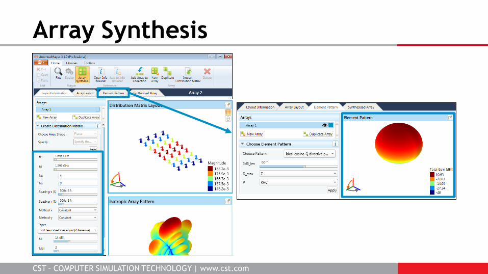
Array Synthesis
CST – COMPUTER SIMULATION TECHNOLOGY | www.cst.com
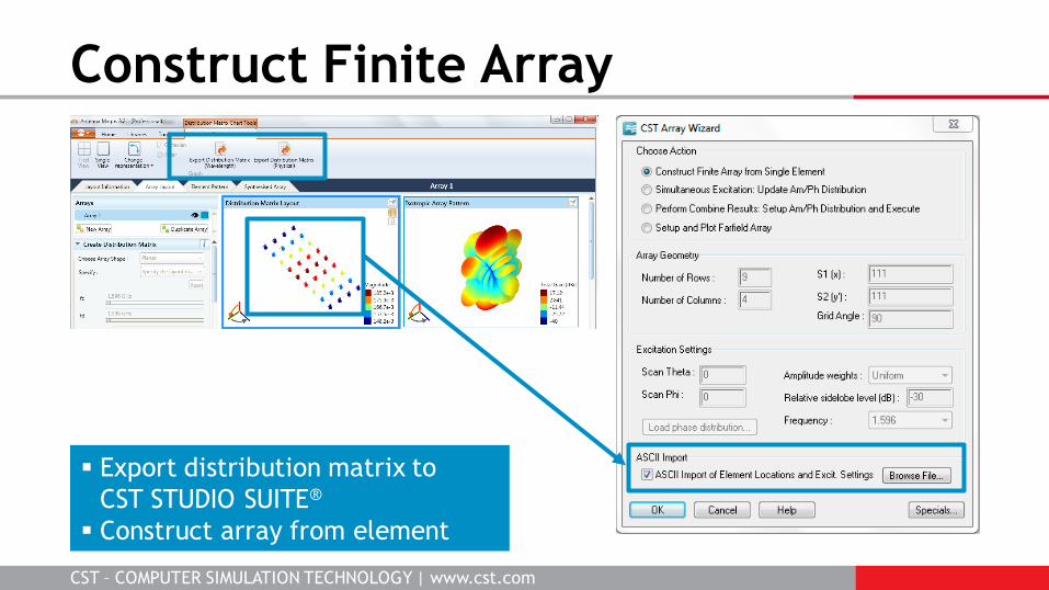
Construct Finite Array
Export distribution matrix to
CST STUDIO SUITE®
Construct array from element

CST – COMPUTER SIMULATION TECHNOLOGY | www.cst.com
Simulation Results
Finite array with no beam steering (main lobe
is broadside).
Simulation requires 1.5 GB RAM and 1.25 hours
on a standard issue laptop.
CST – COMPUTER SIMULATION TECHNOLOGY | www.cst.com
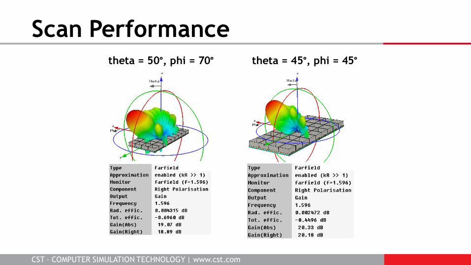
Scan Performance theta = 45°, phi = 45° theta = 50°, phi = 70°

CST – COMPUTER SIMULATION TECHNOLOGY | www.cst.com
Simulated Like Measured Standard ARINC 781 ground plane 2.4 x 1.6 m section of a 3m radius cylinder
CST – COMPUTER SIMULATION TECHNOLOGY | www.cst.com
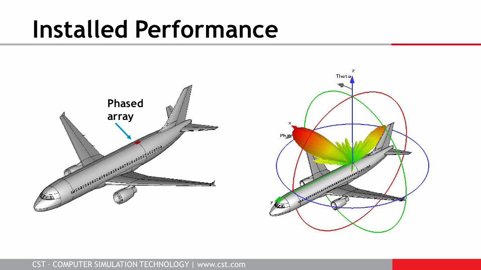
Installed Performance
Phased
array
CST – COMPUTER SIMULATION TECHNOLOGY | www.cst.com
Large library of antennas
New designs are easy
Quick estimation functionality
Include your own antenna in the library
Exports are parameterized
Perfect companions to CST STUDIO SUITE®
Conclusion