Inline Pumps Inline-Pumpen Pompe Inline - maral.biz · nevoilor pieţei, oferă pompa corectă...
56
Pompe Inline Inline-Pumpen Inline Pumps EBZ-V/EBZ-E Mai mult decât pompe 08 0134.0111_EBZ_OST_2 _EBZ_2005/3 D_F_E 18.05.12 08:23 Seite 1
Transcript of Inline Pumps Inline-Pumpen Pompe Inline - maral.biz · nevoilor pieţei, oferă pompa corectă...
Pompe InlineInline-PumpenInline Pumps
EBZ-V/EBZ-E
Mai mult decât pompe
08 0134.0111_EBZ_OST_2 _EBZ_2005/3 D_F_E 18.05.12 08:23 Seite 1
Cine doreşte să supravieţuiască în cadrulconcurenţei actuale acerbe, nu se poatelimita la a cumpăra numai de la furnizoriieftini. Numai cine a învăţat să îşi aleagă partenerii în mod corect şi să le folosească punctele forte pentru afacerea sa, va putea avea profituri şi succes pe termen lung.
O întreagă gamă de servicii ajută clienţiiBiral să devină mai puternici. Servicii, care economisesc timp şi bani,evită situaţiile tensionate şi erorile.
Printre acestea se numără în primul rând:
– Gama de produse bine structuratăO gamă clară de produse, adecvată nevoilor pieţei, oferă pompa corectă pentru fiecare aplicaţie. Tehnologia bine concepută şi caracteristicile stabile garantează funcţii fiabile, silenţioase cu un consum redus de energie.
– Echipa de consiliere:Specialişti instruiţi, disponibili de fiecare dată. Aceştia îi susţin pe partenerii noştri la calcularea şi la alegerea pompei corecte, la diagnosticarea erorilor şi cu indicaţii pentru montaj.
– Date sigure şi documentaţie cuprinzătoare:Acestea sunt bazele pentru orice proiectare a pompelor. Acestea sunt perfecte pentru teoreticieni şi utile pentru cei practici, pentru a obţine cu uşurinţă rezultatul dorit.
– Departamentul de logistică:Sarcina lor: livrarea pompelor şi a pieselor de schimb la timp şi fără erori.
Wer im heutigen Konkurrenzkampf überleben will, kann sich auch gegenüberLieferanten nicht darauf beschränken, billig einzukaufen. Nur wer es gelernt hat,seine Partner richtig auszuwählen undihre Stärken für sein eigenes Geschäft zu nutzen, wird Geld verdienen und langfristig erfolgreich sein können.
Eine ganze Palette von Dienstleistungenhilft den Kunden von Biral, stärker zuwerden. Dienstleistungen, die Zeit und Kosten sparen, Ärger vermeiden,Fehler verhindern.
In erster Linie gehören dazu:
– Das gut strukturierte Sortiment:Eine klare, auf die Marktbedürfnisse abgestimmte Sortimentsstruktur bietet für jede Anwendung die richtige Pumpe. Die ausgeklügelte Technik und die stabilen Kennlinien gewähr-leisten zuverlässige, geräuscharme Funktionen bei geringstem Energieverbrauch.
– Das Beratungsteam:Ausgewiesene Fachleute, jederzeit erreichbar. Sie unterstützen unsere Partner bei der Berechnung und bei der Auswahl der richtigen Pumpe, bei Fehlerdiagnosen und mit Installationshinweisen.
– Sichere Daten und übersichtliche Dokumentation:Sie sind die Grundlage für jede Planung und Pumpenauslegung. In ihrer Aufbereitung sind sie für den Theoretiker perfekt und begeisternd für den Praktiker, den sie mit Leichtigkeit zum gewünschten Resultat führen.
– Die Logistik:Ihre Aufgabe: Die Auslieferung von Pumpen und Ersatzteilen erfolgt termingerecht und fehlerfrei.
Those who want to survive in the presentday competitive environment cannot limit themselves to cheap purchases,even with respect to suppliers. Only those who have learnt to takeadvantage of the strengths of the rightpartners for their own business will besuccessful and profitable in the long term.
A whole range of services helps Biral customers to become stronger. Services to save time and money, avoid annoyance and prevent defects.
These mainly include:
– A well-structured product range:A clear range of products structured to match the demands of the market provides the right pump for every application. The well-devised engineering and stable characteristic curves ensure reliable, quiet functions with minimum energy consumption.
– The advisory team:Qualified specialists who are always accessible. They support our partners in the calculation and selection of the right pump with fault diagnoses and installation instructions.
– Reliable data and clear documentation:These form the basis for all planning and pump design. They are perfect in their preparation for the theorist and useful for the practician to easily achieve the desired result.
– Logistics:Requirement: delivery of pumps and spare-parts in good time and free from faults.
De ce merită să alegeţi BiralWarum es sich lohnt, Biral zu wählenWhy it’s always worth choosing Biral
2
08 0134.0111_EBZ_OST_2 _EBZ_2005/3 D_F_E 18.05.12 08:23 Seite 2

Servicii:Succes pentru partenerii BiralDienstleistungen:Erfolg für Biral-PartnerServices:success for Biral partners
Gama de produseProdukte-BereichProduct range P
oten
ţial d
e câ
ştig
/Ver
die
nst
-Po
ten
zial
/Ear
nin
gs
po
ten
tial
Servicii de consiliereBeratungs-DienstleistungenConsulting services
Asistenţă şi susţinerepe termen lungLangfristige Begleitungund UnterstützungLong-term back-up and support
Pompe excelente: Calitate elveţianăAusgezeichnete Pumpen: Swiss QualityExcellence in pumps: Swiss Quality
Structura gamei conform situaţiilor de utilizareSortiments-Struktur gemäss AnwendungssituationenProduct range structure according to application situations
ConsiliereBeratungAdvice
Documentaţie şi instrucţiuni pentru montajDokumentation und AuslegungshilfenDocumentation and layout assistance
Instruire şi formareSchulung und AusbildungTraining and instruction
Servicii de livrareLieferserviceDelivery service
Service non-stopService 24 Stunden24-hour service (Switzerland only)
Serviciu de reparaţii şi piese de schimbReparatur- und ErsatzteildienstRepair and spare-parts service
– Echipa de service:Aceasta nu cunoaşte numai pompele, ci şi cum funcţionează instalaţia, unde pot apărea probleme şi cum se pot rezolva acestea. Angajaţii, care îi asistă pe partenerii noştri, măsoară, repară, înlocuiesc şi consiliază: zi şi noapte, 7 zile pe săptămână.
Dar în centrul tuturor acestor servicii se află mândria noastră: pompa. O minune a tehnicii – economică, silenţioasă şi robustă, sigură din punctulde vedere al funcţionării şi adaptabilă.
– The service team:These people not only know the pumps, but also how the system functions, where problems may lie and how they can be solved. Personnel supporting our partners measure, repair, exchange and advise: day and night, 7 days a week.
Our proud centrepiece of all these services, however, is the pump. A technical marvel – energy-saving, quiet and robust, reliable in operationand adaptable.
3
– Die Service-Equipe:Sie kennt nicht nur die Pumpen, sondern weiss, wie die Anlage funktioniert, wo Probleme liegen können und wie sie zu lösen sind. Mitarbeiter, die unsere Partner unterstützen, messen, reparieren, auswechseln und beraten: Tag und Nacht, 7 Tage in der Woche.
Im Zentrum all dieser Leistungen abersteht unser ganzer Stolz: die Pumpe. Ein technisches Wunderwerk – energiesparend, leise und robust, betriebssicher und anpassungsfähig.
08 0134.0111_EBZ_OST_2 _EBZ_2005/3 D_F_E 18.05.12 08:23 Seite 3

Pompe Biral InlineEBZ-V, EBZ-E
Pompe centrifugale cu o singură treaptă,cu economie de energie şi construcţiecompactă, cu fiabilitate sporită. Cu caracteristici stabile, acestea au o funcţionare economică şi sunt uşor de montat şi de demontat. Gama bine structurată cu diferite dimensiuni şi posibilităţi de montaj, domeniu de utilizare amplu pentru pomparea apei calde şi reci, în special în instalaţiile de încălzire şi climatizare.
Pompa EBZ-E comandată electronic cu convertizor de frecvenţă integrat se adaptează automat la valori de presiune şi volume de apă variabile.Randament optim fără producere de zgomote.
Biral-Inline-PumpenEBZ-V, EBZ-E
Einstufige, energiesparende und kompakt konstruierte Zentrifugalpumpen von hoher Zuverlässigkeit. Sie haben stabile Kennlinien, sind sparsam und wirtschaftlich im Betriebund einfach montier- und demontierbar.Fein abgestimmtes Sortiment unterschiedlichster Grössen undEinbaumöglichkeiten, breiterEinsatzbereich zur Förderung von Warm- und Kaltwasser vor allem in Heizungs- und Klimaanlagen.
Die elektronisch gesteuerte Pumpe EBZ-E mit integriertem Frequenz-umformer passt sich automatisch anvariable Druck- und Wassermengen an.Optimaler Wirkungsgrad ohneGeräuschentwicklung.
Biral Inline PumpsEBZ-V, EBZ-E
Single-stage, energy-saving centrifugalpumps of compact construction and high reliability. With stable characteristiccurves, they are economical in use, efficient in operation and easily installedand removed. A finely-graded range in many different sizes and possibleinstallations, a wide field of application to convey hot and cold water above all in heating and air-conditioning systems.
The EBZ-E electronically controlled pump with integral frequency converteradapts automatically to variable pressures and water volumes. Optimum efficiency and quiet operation.
Pompa adecvată pentru fiecare aplicaţieFür jeden Einsatz die geeignete PumpeThe best pump for every application
4
Dimensiuni în mmNe rezervăm dreptul de a efectua modificări tehnice
Abmessungen in mmTechnische Änderungen vorbehalten
Dimensions in mmTechnical changes reserved
08 0134.0111_EBZ_OST_2 _EBZ_2005/3 D_F_E 18.05.12 08:23 Seite 4
EBZ-V, EBZ-E
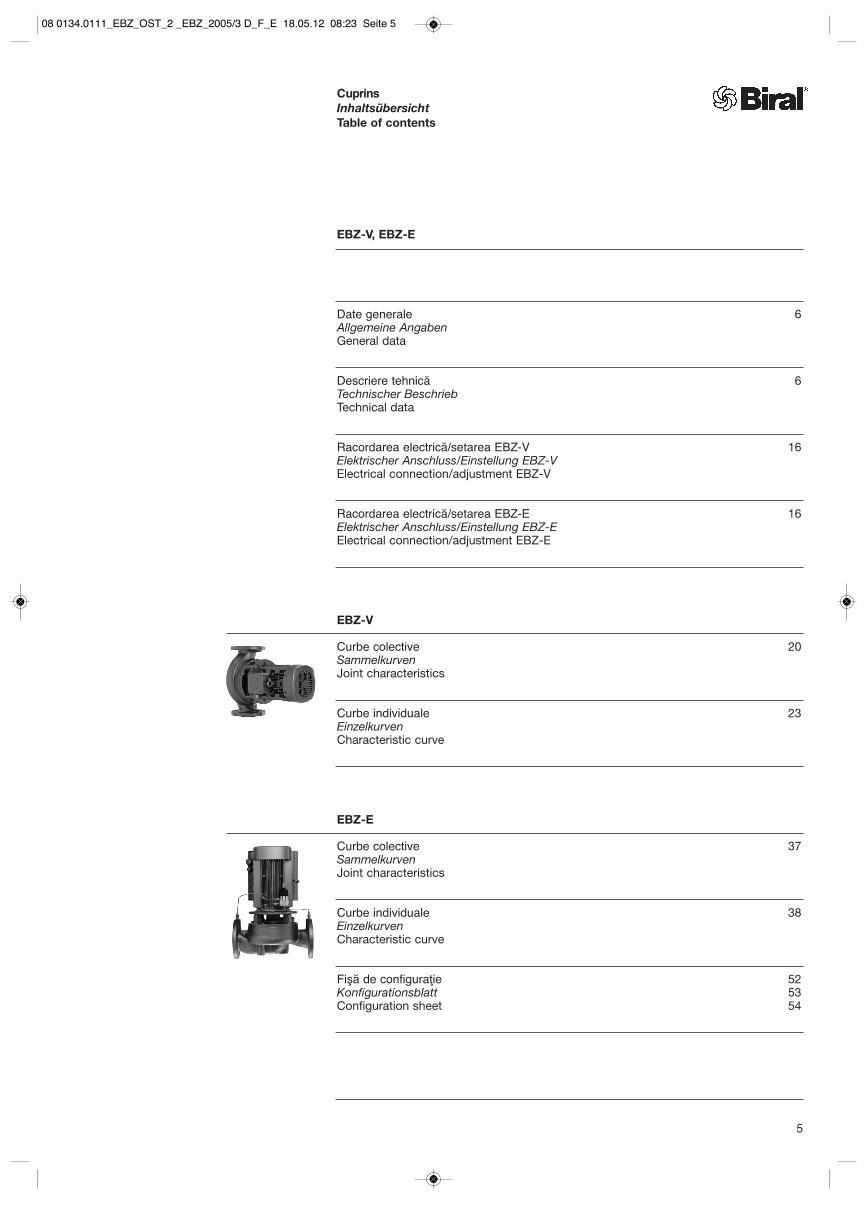
Date generale 6Allgemeine AngabenGeneral data
Descriere tehnică 6Technischer Beschrieb Technical data
Racordarea electrică/setarea EBZ-V 16Elektrischer Anschluss/Einstellung EBZ-VElectrical connection/adjustment EBZ-V
Racordarea electrică/setarea EBZ-E 16Elektrischer Anschluss/Einstellung EBZ-EElectrical connection/adjustment EBZ-E
EBZ-V
Curbe colective 20Sammelkurven Joint characteristics
Curbe individuale 23Einzelkurven Characteristic curve
EBZ-E
Curbe colective 37Sammelkurven Joint characteristics
Curbe individuale 38Einzelkurven Characteristic curve
Fişă de configuraţie 52Konfigurationsblatt 53Configuration sheet 54
CuprinsInhaltsübersichtTable of contents
5
08 0134.0111_EBZ_OST_2 _EBZ_2005/3 D_F_E 18.05.12 08:23 Seite 5

Pompe Biral Inline
Pompele Biral Inline sunt pompe centrifugale cu o singură treaptă, cu economie de energie şi cu contrucţie compactă.Pompele se evidenţiază în special prin siguranţa funcţionării şi fiabilitateasuperioare.
Biral Inline Pumps
Biral Inline pumps are compactly-constructed, single-stage centrifugalpumps with a particularly low energy consumption.These pumps are distinguished by theirhigh level of operational safety and their reliability.
Biral-Inline-Pumpen
Biral-Inline-Pumpen sind einstufige, energiesparende und kompakt konstruierte Zentrifugalpumpen.Die Pumpen zeichnen sich besondersdurch grosse Betriebssicherheit undZuverlässigkeit aus.
Avantajele• Gamă bine structurată
Construcţie compactăNivel de zgomot redus (turaţie joasă)
• Caracteristici stabileÎnălţimea de pompare scade odatăcu creşterea debitului
• Randament bunFuncţionare economică
• Service uşorLa demontarea unităţii de acţionare,carcasa în spirală poate rămâneîn conductă
• Garnitura arborelui fără întreţinereDrept garnituri ale arboreluise utilizează etanşări mecanice (GLRD).
Domenii de utilizarePompele Biral Inline sunt adecvate în special pentru:• Instalaţiile de încălzire şi ventilare• Instalaţiile de climatizare şi răcire• Alimentările cu apă• Instalaţiile industriale• Irigaţii şi drenări
în agricultură
Lichidele pompatePentru pomparea apei pure, de încălzire(conform VDI 2035) şi menajere, a condensului şi a altor medii cu vâscozitate redusă şi fără uleiuri mineralesau particule abrazive sau cu fibre lungi,care nu atacă chimic materialele, precumşi a amestecurilor cu conţinut de glicol de maximum 50% (de la conţinutul de glicol de 25% se foloseşte o garnitură glisantă specială).
În cazul vâscozităţii cinematice mai mari decât a apei, trebuie să se verificeputerea motorului. In cazul fluidelor, cum ar fi uleiul etc., trebuie să se verifice GLRD.
Advantages• Well-graded programme
Compact constructionQuiet operation (low speed)
• Stable characteristic curvesThe delivery head decreases with increasing delivered volume
• High efficiencyEconomical in operation
• Service-friendlyThe spiral housing can be left in the pipe when removing the drive unit
• Shaft seal maintenance-freeFloating ring seals (GLRD) are used as shaft seals.
Fields of applicationThe Biral Inline pumps are useful for:
• heating and air-conditioning installations
• water supplies• industrial plants• irrigation and drainage
in agriculture
Pumping liquidsFor pumping pure-, heating and servicewater, condensate and other low viscosity, petroleum-free media withoutabrasive or long fibre components, which do not attack the materials chemically, as well as mixtureswith a maximum 50% glycol content (special face seal from 25% glycol content).
The motor capacity must be checked for higher kinematic viscosity than water.The GLRD must be checked for mediasuch as oil, etc.
Vorteile• Gut gestuftes Programm
Kompakte BauweiseGeräuscharm (niedertourig)
• Stabile KennlinienDie Förderhöhe nimmt mit zunehmender Fördermenge ab
• Guter WirkungsgradSparsam und wirtschaftlich im Betrieb
• ServicefreundlichBeim Ausbau der Antriebseinheit kann das Spiralgehäuse in der Rohrleitung verbleiben
• Wellendichtung wartungsfreiAls Wellendichtungen werden Gleitringdichtungen (GLRD) eingesetzt.
EinsatzgebieteBiral-Inline-Pumpen eignen sich ausgezeichnet für:• Heizungs- und Lüftungsanlagen• Klima- und Kälteanlagen• Wasserversorgungen• Industrieanlagen• Be- und Entwässerung
in der Landwirtschaft
FörderflüssigkeitenZur Förderung von Rein-, Heizungs- (nach VDI 2035) und Brauchwasser,Kondensat und anderen dünnflüssigenmineralölfreien Medien ohne abrasiveoder langfaserige Bestandteile, die die Werkstoffe chemisch nicht angreifen,sowie Gemische mit maximum 50%Glykolanteil (ab 25% Glykolanteil spezielle Gleitringdichtung).
Bei höherer kinematischer Zähigkeit alsWasser muss die Motorleistung überprüftwerden. Bei Medien wie Öl usw. mussGLRD überprüft werden.
6
08 0134.0111_EBZ_OST_2 _EBZ_2005/3 D_F_E 18.05.12 08:23 Seite 6

Construction form: B5/B14
Efficiency class: IE2 three-phase motors �0,75 kW
Type of protection: IP 55
Insulation class: F
Voltage/frequency: 3× 400V/50 Hz
Motor protection: WSK 150 °C
Speed: 1450 rpm
2900 rpm
Ambient temperature: up to 40 °C
Bauform: B5/B14
Effizienzklasse:IE2 dreiphasige Motoren �0,75 kW
Schutzart: IP 55
Isolationsklasse: F
Spannung/Frequenz: 3×400V/50 Hz
Motorschutz: WSK 150 °C
Drehzahl: 1450 1/min
2900 1/min
Umgebungstemperatur: bis 40 °C
Forma constructivă: B5/B14
Clasa de eficienţă:Motoare trifazate IE2 �0,75 kW
Clasa de protecţie: IP 55
Clasa de izolare: F
Tensiune/frecvenţă: 3×400V/50 Hz
Protecţia motorului: WSK 150 °C
Turaţia: 1450 1/min
2900 1/min
Temperatura ambiantă: până la 40 °C
LagărLagăre montate în motor, lubrifiate permanent, care nu necesită întreţinere.
Mecanismul de acţionareMotor trifazat cu suprafaţa răcită şi arbore motor prelungit
LagerungIm Motor eingebaute, dauerfett-geschmierte, wartungsfreie Wälzlager.
AntriebOberflächengekühlter Drehstrom-Kurzschlussläufermotor mit verlängerter Motorwelle
BearingPermanently greased, maintenance-freeroller bearing integrated in motor.
DriveTotally enclosed, fan-cooled, three-phase squirrel-cage motor with extended motor shaft
7
ConstrucţiaPompe cu carcasă spirală cu o singurătreaptă şi rotor radial închis. Construcţie pentru montajul orizontal sau vertical.Duzele de aspiraţie si refulare cu aceleaşi dimensiuni ale flanşelor sunt dispuse în linie.Motorul cu arbore prelungit este fixat cu flanşe direct pe carcasa pompei.Garnitura arborelui cu garnitură glisantă. Pompele trebuie să pompeze doar pe o perioadă scurtă cu robinetul inchis.Cantitatea minimă de pompare: 10% din cantitatea max. de pompare
KonstruktionEinstufige Spiralgehäusepumpen mit geschlossenem Radial-Laufrad.Ausführung für horizontalen oder vertikalen Einbau.Saug- und Druckstutzen mit den gleichen Flanschabmessungen sind in einer Linieangeordnet.Motor mit verlängerter Welle direkt am Pumpengehäuse angeflanscht.Wellendichtung mit Gleitringdichtung. Pumpen dürfen nur kurzzeitig gegengeschlossenen Schieber fördern.Minimale Fördermenge: 10% von der max. Fördermenge
ConstructionSingle-stage spiral housing pumps with enclosed radial impeller. Version for horizontal or vertical mounting.Suction and discharge branches are placed in line with equal flange dimensions.Motor with extended shaft flanged directly to pump housing.Shaft sealed with floating ring seal.Pumps must only deliver briefly against closed slide valves.Minimum deliveries: 10% of max. delivery
1 Carcasa pompeiPumpengehäusePump housing
2 RotorLaufradImpeller
3 Garnitura glisantă (GLRD)Gleitringdichtung (GLRD)Floating ring seal (GLRD)
4 MotorMotorMotor
EBZ-V1 2 3 4
Nivelurile de eficienţă ale motoarelorEffizienzniveaus von MotorenEfficiency levels of motors
Reglementarea (CE) nr. 640/2009Verordnung (EG) Nr. 640/2009Regulation (EU) no. 640/2009
2011 IE2 este obligatorie de acum!IE2 ab sofort Pflicht!IE2 mandatory with immediate effect
2015IE3 7,5 kW până la 375 kW sau IE2 cu FUIE3 7,5 kW bis 375 kW oder IE2 mit FU IE3 7,5 kW to 375 kW or IE2 with FC
2017IE3 0,75 kW până la 375 kW sau IE2 cu FUIE3 0,75 kW bis 375 kW oder IE2 mit FUIE3 0,75 kW to 375 kW or IE2 with FC
08 0134.0111_EBZ_OST_2 _EBZ_2005/3 D_F_E 18.05.12 08:23 Seite 7

1 Temperaturile admise sunt valabilepentru apă. În cazul altor lichide pompatelimitele de temperatură se pot modifica.
8
Zulässiger EintrittsdruckEintrittsdruck plus Förderhöhe (bei 0 Menge) dürfen den max. zulässigenBetriebsdruck (Pumpenenddruck) nicht überschreiten. Dieser ist abhängigvon der eingesetzten Gleitringdichtung.
Wellendichtung (GLRD)
Standard-Ausführungen bis 25% Glykol
GLRD V-1 MG1 Hartkohle- Siliziumkarbid
Temperatur1 t: –10 °C bis +140 °C
Pumpenenddruck p: 10 bar
bis 50% Glykol
GLRD V-3 MG1 reduzierte Gleitfläche Siliziumkarbid-
Siliziumkarbid
Temperatur1 t: –20 °C bis +60 °C
Pumpenenddruck p: 10 bar
Sonder-AusführungenAbrasive Kleinstteile im Medium:
GLRD V-2 MG1 Siliziumkarbid- Siliziumkarbid
Temperatur1 t: 0 °C bis +90 °C
Pumpenenddruck p: 10 bar
Erhöhter Druck 16 bar/13 bar:
GLRD K-1 HJ92N Hartkohle-entlastet Siliziumkarbid
Temperatur1 t: 0 °C bis +120 °C
Pumpenenddruck p: 16 bar
oder
Temperatur1 t: 0 °C bis +140 °C
Pumpenenddruck p: 13 bar
Weitere Ausführungen auf Anfrage
Die GLRD ist ein Verschleissteil. Je nach Betriebsbedingungen und Medium kann eine gewisse Leckageauftreten. Bei speziellen Medien oderZusätzen aus Frost-/Rostschutz muss dieWahl der GLRD überprüft werden.Gleitringdichtungen nach DIN 24960
1 Die zulässigen Temperaturen geltenfür Wasser. Bei anderen Förderflüssigkeitenkönnen sich die Temperaturgrenzen ändern.
Permissible inlet pressure Inlet pressure plus delivery height (at 0 volume) must not exceed the maximum permissible operating pressureDo not exceed (pump end pressure). This depends on the slide ring seal used.
Shaft seal (SRS)
Standard designup to 25% glycol
SRS V-1 MG1 Hard carbonSilicone carbide
Temperature1 t: –10 °C to +140 °C
Pump end pressure p: 10 bar
Up to 50% glycol
SRS V-3 MG1reduced sliding surface Silicone carbide-
Silicone carbide
Temperature1 t: –20 °C to +60 °C
Pump end pressure p: 10 bar
Special designsAbrasive micro-components in the medium:
GLRD V-2 MG1 Silicone carbide- Silicone carbide
Temperature1 t: 0 °C to +90 °C
Pump end pressure p: 10 bar
Increased pressure, 16 bar/13 bar:
SRS K-1 HJ92N Hard carbonreleased Silicone carbide
Temperature1 t: 0 °C to +120 °C
Pump end pressure p: 16 bar
or
Temperature1 t: 0 °C to +140 °C
Pump end pressure p: 13 bar
Other designs upon request
1 The admissible temperatures refer to water.For different pumping liquids the temperature limit may change.
The slide ring seal is a wearing part.Depending on the operating conditionsand medium, a certain degree of leakagemay arise. For special media or additivesfor frost/corrosion protection, the choiceof SRS must be verified. Slide ring seals according to DIN 24960.
Presiune de intrare permisăPresiunea de intrare plus înălţimea de pompare nu trebuie să depăşeascăpresiunea de funcţionare max. permisă(presiunea finală a pompei). Aceasta depinde de etanşarea mecanicăutilizată.
Garnitura arborelui (GLRD)
Construcţii standard până la 25% glicol
GLRD V-1 MG1 Cărbune dur- Carbură de siliciu
Temperatura1 t: –10 °C până la +140 °C
Presiunea finală a pompei p: 10 bar
până la 50% glicol
GLRD V-3 MG1 suprafaţă glisantă Carbură de siliciu- redusă Carbură de siliciu
Temperatura1 t: –20 °C până la +60 °C
Presiunea finală a pompei p: 10 bar
Construcţii specialeParticule mici abrazive în fluid:
GLRD V-2 MG1 Carbură de siliciu- Carbură de siliciu
Temperatura1 t: 0 °C până la +90 °C
Presiunea finală a pompei p: 10 bar
Presiune crescută 16 bar/13 bar:
GLRD K-1 HJ92N Cărbune dur-echilibrat Carbură de siliciu
Temperatura1 t: 0 °C până la +120 °C
Presiunea finală a pompei p: 16 bar
sau
Temperatura1 t: 0 °C până la +140 °C
Presiunea finală a pompei p: 13 bar
Alte construcţii la cerere
GLRD este o piesă de uzură. În funcţie de condiţiile de funcţionare şide fluid, poate apărea o scurgere. În cazul fluidelor speciale sau al adăugăriide antigel/soluţie anti-corozivă, trebuie să se verifice alegerea GLRD.Etanşări mecanice conform DIN 24960
08 0134.0111_EBZ_OST_2 _EBZ_2005/3 D_F_E 18.05.12 08:23 Seite 8

9
Ausführungen EBZ-V und EBZ-E
Standard
Gehäuse normal lackiert und Standard GLRD
Mediumstemperatur: 0 °C bis +140 °C
Kaltwasser
Gehäuse mit spez. kondenswasser-beständigem Schutzanstrich und Standard GLRD
Mediumstemperatur: –10 °C bis +95 °C
Empfohlen bei Mediumstemperatur <15 °C
Kaltwasser/Glykol
Gehäuse mit spez. kondenswasser-beständigem Schutzanstrich und GLRD für erhöhten Glykol-Anteil
Mediumstemperatur: –20 °C bis +60 °C
Motorschutz EBZ-VDie Motoren sind serienmässig mit Wicklungsschutzkontakten (WSK 150 °C) ausgerüstet. Sie müssen mit einem entsprechendenMotorschutzschalter versehen werden.Erdung nach örtlichen Vorschriften.
Werkstoffe
EBZ-V 35, 45, 55, 65, 85, 100EBZ-E 45, 55, 65, 85, 100
Pumpengehäuse EN-GJL-250 (GG 25)
Gehäusedeckel EN-GJL-250 (GG 25)
EBZ-V 40, 50, 67, 87, 102, 126, 150EBZ-E 102, 126, 150
Pumpengehäuse EN-GJS-400 (GGG 40)
Gehäusedeckel EN-GJS-400 (GGG 40)
alle
Laufrad EN-GJL-200 (GG 20)Aus Bronze auf Anfrage
Welle (1.4057) X17 Cr Ni 16-2
Wellenhülse G-Cu Sn 5
Bei Einsatz der Pumpe auch einschlägige Gesetze und Vorschriften(z. B. DIN 4747 oder DIN 4752, Abschnitt 4,5) beachten.
EBZ-V and EBZ-E designs
Standard
Casing painted normaland standard SRS
Medium temperature: 0 °C to +140 °C
Cold water
Casing with special paint to protectagainst condensation water and standard SRS
Medium temperature: –10 °C to +95 °C
Recommended for medium temperature <15°C
Cold water/glycol
Casing with special paint to protectagainst condensation water and SRS for increased glycol proportions
Medium temperature: –20 °C to +60 °C
EBZ-V motor protectionThe motors are fitted with winding protection (WSK 150 °C) as standard.They must be equipped with an appropriate motor protection holder and earthed according to local regulations.
Materials
EBZ-V 35, 45, 55, 65, 85, 100EBZ-E 45, 55, 65, 85, 100
Pump casing EN-GJL-250 (GG 25)
Casing cover EN-GJL-250 (GG 25)
EBZ-V 40, 50, 67, 87, 102, 126, 150EBZ-E 102, 126, 150
Pump casing EN-GJS-400 (GGG 40)
Casing cover EN-GJS-400 (GGG 40)
all
Impeller EN-GJL-200 (GG 20)Made of bronze on request
Shaft (1.4057) X17 Cr Ni 16-2
Shaft sleeve G-Cu Sn 5
When using the pump, also take accountof relevant laws and regulations(e.g. DIN 4747or DIN 4752, extract 4.5).
Construcţiile EBZ-V şi EBZ-E
Standard
Carcasă vopsită normalşi GLRD standard
Temperatura fluidului: 0 °C până la +140 °C
Apă rece
Carcasă cu strat de protecţie specialrezistent la condens şi GLRD standard
Temperatura fluidului: –10 °C până la +95 °C
Se recomandă la temperatura fluidului <15 °C
Apă rece/glicol
Carcasă cu strat de protecţie specialrezistent la condens şi GLRD pentru un conţinut mai mare de glicol
Temperatura fluidului: –20 °C până la +60 °C
Protecţia motorului EBZ-VMotoarele sunt echipate în serie cu contacte de protecţie a bobinelor (WSK 150 °C). Acestea trebuie să fieprevăzute cu un comutator corespunzătorde protecţie a motorului.Împământare conform prevederilor locale.
Materiale
EBZ-V 35, 45, 55, 65, 85, 100EBZ-E 45, 55, 65, 85, 100
Carcasa pompei EN-GJL-250 (GG 25)
Capacul carcasei EN-GJL-250 (GG 25)
EBZ-V 40, 50, 67, 87, 102, 126, 150EBZ-E 102, 126, 150
Carcasa pompei EN-GJS-400 (GGG 40)
Capacul carcasei EN-GJS-400 (GGG 40)
toate
Rotor EN-GJL-200 (GG 20)Din bronz la cerere
Arbore (1.4057) X17 Cr Ni 16-2
Manşonul arborelui G-Cu Sn 5
La utilizarea pompei, respectaţi şi legile şi prevederile relevante(de ex. DIN 4747 sau DIN 4752, paragraful 4,5).
08 0134.0111_EBZ_OST_2 _EBZ_2005/3 D_F_E 18.05.12 08:23 Seite 9

E * Evacuare 1
Entleerung 1 G 1/4˝Drain 1
LV AerisireEntlüftung G 1/4˝Vent
M Conexiune manometru 1
Manometeranschluss 1 2× G 1/4˝Pressure gauge connection 1
AspiraţieSaugstutzenSuction branch
RefulareDruckstutzenDischarge branch
RacorduriAnschlüsseConnections
E
MLV
M
* EBZ 87/102/125/150
10
Codul tipuluiTypenschlüsselType designation
ExempluBeispielExample
EBZ SeriaTypenreiheSeries
E Reglarea turaţieiDrehzahlregelungSpeed control
85 Dimensiunea tipuluiTypengrösseSize
V Arbore motor prelungitVerlängerte MotorwelleExtended motor shaft
4 Numărul de poli ai motoruluiPolzahl des MotorsNumber of poles of motor
200 Diametrul rotoruluiLaufraddurchmesserImpeller diameter
(H) Peste frecvenţa nominală (50 Hz) cu impuls înalt la 60 HzÜber Nennfrequenz (50 Hz) hochgetaktet auf 60 HzClocked up to 60 Hz over rated frequency (50 Hz)
EBZ - E 85 V / 4 - 200 (H)
1 dacă existăwenn vorhandenif present
EBZ - V 85 V / 4 - 200
08 0134.0111_EBZ_OST_2 _EBZ_2005/3 D_F_E 18.05.12 08:23 Seite 10

LV
LV
V1a
H1a
Posibilităţi de montajEinbaumöglichkeitenPossible methods for installation
EBZ-V/EBZ-E
Montaj verticalEinbau «Förderrichtung» vertikalVertical installation
Aerisirea LV, indiferent de direcţia de montaj, întotdeauna pe axul vertical, sus
Entlüftung LV, unabhängig von der Einbaurichtung, immer in der Vertikalachse, oben
Ventilation LVindependent of the installation direction, always in the vertical axis, above
Montaj orizontalEinbau «Förderrichtung» horizontalHorizontal installation
Aerisirea LV, indiferent de direcţia de montaj, întotdeauna pe axul vertical, susExcepţie: H1 şi H1a
Entlüftung LV, unabhängig von der Einbaurichtung, immer in der Vertikalachse, obenAusnahme: H1 und H1a
Ventilation LVindependent of the installation direction, always in the vertical axis, aboveException: H1 and H1a
În cazul capacităţii portante insuficiente a conductei, pompele de la lăţimea nominală DN 80 mm pot fi fixate cu un picior pe o consolă de perete.
Bei ungenügender Tragfähigkeit der Rohrleitung können Pumpen ab Nennweite DN 80 mm mit einem Fuss an einer Wandkonsole befestigt werden.
If the piping is not sufficiently stable, pumps with a nominal diameter of DN 80 mm and upwards can be attached to a wall bracket.
LV
LV
LV
LV LV
LV
V1
V2
H1
H2
H3
H3
11
961471.00
961471.00
9614
71.0
0
961471.00
08 0134.0111_EBZ_OST_2 _EBZ_2005/3 D_F_E 18.05.12 08:23 Seite 11

Presiunea de funcţionare necesară(valori orientative)
– Sisteme închiseÎnălţimi de admisie minime pentru sisteme închise (Suprapresiunea necesară la duza de aspiraţie a pompei). Locul de amplasare 500 m peste nivelul mării. Pentru fiecare ±100 m altitudine peste nivelul mării presiunea de funcţionare necesară se modifică cu ± 0,01 bar.
Erforderlicher Betriebsdruck(Richtwerte)
– Geschlossene SystemeMinimale Zulaufhöhen für geschlossene Systeme (Erforderlicher Überdruck bei Betriebam Saugstutzen der Pumpe).Aufstellungsort 500 m über Meer. Pro ±100 m Höhe über Meer ändert der erforderliche Betriebsdruck um ±0,01 bar.
Required operating pressure(nominal values)
– Closed systemsMinimum supply elevations for closed systems (required excess pressure at the pumps suction intakes). The values apply for hot-water production plants.Place of installation 500 m above sealevel. Per ±100 m altitude above mean sea level alters the required operating pressure by ±0.01 bar.
Suprapresiunea necesară în bar:Erforderlicher Überdruck in bar:Required excess pressure in bar.
12
Regim de aspiraţie SaugbetriebSuction operation
Regim de admisieZulaufbetriebSupply operation
H (+)
H (–)NPSH
Hf
PbHFig. 1
Tipul pompei TemperaturaPumpentyp TemperaturPump type Temperature
EBZ 60 °C 75 °C 90 °C 110 °C 140 °C
EBZ 35 V/4 0,0 0,2 0,8 2,1 5,6
EBZ 35 V/2 0,2 0,6 1,2 2,5 6,0
EBZ 40 V/4 1,1 1,4 2,0 3,3 6,9
EBZ 45 V/4 EBZ-E 45 V/4 0,0 0,4 1,0 2,3 5,8
EBZ 45 V/2 EBZ-E 45 V/2 0,8 1,2 1,8 3,1 6,6
EBZ 50 V/4 1,1 1,4 2,0 3,3 6,9
EBZ 55 V/4 EBZ-E 55 V/4 0,4 0,8 1,4 2,7 6,3
EBZ 55 V/2 EBZ-E 55 V/2 1,6 2,0 2,6 3,9 7,4
EBZ 65 V/4 EBZ-E 65 V/4 0,4 0,7 1,3 2,6 6,2
EBZ 65 V/2 EBZ-E 65 V/2 1,5 1,9 2,5 3,8 7,4
EBZ 67 V/4 0,7 1,1 1,7 3,0 6,5
EBZ 85 V/4 EBZ-E 85 V/4 0,2 0,5 1,1 2,4 6,0
EBZ 87 V/4 1,0 1,4 2,0 3,3 6,8
EBZ 100 V/4 EBZ-E 100 V/4 0,3 0,7 1,3 2,6 6,1
EBZ 102 V/4 EBZ-E 102 V/4 0,8 1,2 1,8 3,1 6,6
EBZ 126 V/4 EBZ-E 126 V/4 0,4 0,8 1,4 2,7 6,2
EBZ 150 V/4 EBZ-E 150 V/4 0,4 0,8 1,4 2,7 6,3
08 0134.0111_EBZ_OST_2 _EBZ_2005/3 D_F_E 18.05.12 08:23 Seite 12

13
Sisteme deschise(valori orientative)
In funcţie de valoarea NPSH a pompei,temperatura fluidului şi presiunea aerului,pe circuitul de aspiraţie al pompeieste admisă o înălţime de aspiraţie max. sau este necesară o admisie min. in metri (evitarea cavitaţiei).
În cazul presiunii normale a aerului (1013 mbar), aceste valori se pot preluadin diagramă Fig. 2.Pierderile de presiune din conducta de aspiraţie nu sunt luate în considerare(inălţimea de aspiraţie este redusă corespunzător; admisia min. trebuie să fie crescută corespunzător).Este inclusă încărcarea de siguranţă de 0,5 m.
Offene Systeme(Richtwerte)
Maximale Saughöhe – minimaler ZulaufdruckJe nach NPSH-Wert der Pumpe,Medientemperatur und Luftdruck ist auf der Saugseite der Pumpe einemax. Saughöhe zulässig oder ein mind. Zulauf in Meter notwendig(Vermeidung von Kavitation).
Bei Normalluftdruck (1013 mbar) könnendiese Werte aus dem Diagramm Fig. 2entnommen werden.Druckverluste in der Saugleitung sindnicht berücksichtigt (Saughöhe wirdentsprechend reduziert; mind. Zulaufmuss entsprechend erhöht werden).Sicherheitszuschlag von 0,5 m ist eingerechnet.
Open systems(nominal values)
Maximum suction head –minimum supply pressureA max. suction head is permissible on the suction side of the pump or a min. supply necessary in metresdepending on the NPSH value of thepump, medium temperature and air pressure (avoidance of cavitation).
At normal air pressure (1013 mbar) these values can be obtained from the diagram fig. 2.Pressure losses in the suction pipe are not taken into account (suction head is correspondingly reduced; min. supply must be correspondingly increased). Safety margin of 0.5 m is included.
Tipul pompei TemperaturaPumpentyp TemperaturPump type Temperature
EBZ 20 °C 40 °C 60 °C 75 °C 90 °C
EBZ 35 V/4 6,6 4,3 1,5 – 2,3 – 8,3
EBZ 35 V/2 1,6 0,3 – 2,5 – 6,3 –12,3
EBZ 40 V/4 – 6,5 – 7,7 –10,5 –14,3 –20,3
EBZ 45 V/4 EBZ-E 45 V/4 3,6 2,3 – 0,5 – 4,3 –10,3
EBZ 45 V/2 EBZ-E 45 V/2 – 4,5 – 5,7 – 8,5 –12,3 –18,3
EBZ 50 V/4 – 6,5 – 7,7 –10,5 –14,3 –20,3
EBZ 55 V/4 EBZ-E 55 V/4 – 1,0 – 2,2 – 5,0 – 8,8 –14,8
EBZ 55 V/2 EBZ-E 55 V/2 –12,4 –13,7 –16,5 –20,3 –26,3
EBZ 65 V/4 EBZ-E 65 V/4 – 0,3 – 1,5 – 4,3 – 8,1 –14,1
EBZ 65 V/2 EBZ-E 65 V/2 –12,0 –13,2 –16,0 –19,8 –25,8
EBZ 67 V/4 – 3,5 – 4,7 – 7,5 –11,3 –17,3
EBZ 85 V/4 EBZ-E 85 V/4 1,8 0,5 – 2,3 – 6,1 –12,1
EBZ 87 V/4 – 6,5 – 7,7 –10,5 –14,3 –20,3
EBZ 100 V/4 EBZ-E 100 V/4 0,5 – 0,8 – 3,6 – 7,4 –13,4
EBZ 102 V/4 EBZ-E 102 V/4 – 4,5 – 5,7 – 8,5 –12,3 –18,3
EBZ 126 V/4 EBZ-E 126 V/4 – 0,5 – 1,7 – 4,5 – 8,3 –14,3
EBZ 150 V/4 EBZ-E 150 V/4 – 1,0 – 2,2 – 5,0 – 8,8 –14,8
Înălţimile de admisie min., înălţimea de aspiraţie max. in m: Min. Zulaufhöhen, max. Saughöhe in m:Min. supply elevations, max. suction elevations in m:
08 0134.0111_EBZ_OST_2 _EBZ_2005/3 D_F_E 18.05.12 08:23 Seite 13

Exemplu cu Fig. 245 m3/h, 6,5 m Temperatura fluidului 60 °C
EBZ 65 V/4-170
NPSH: 4 m din diagrama pompelor
Inălţimea de aspiraţie maximă: +1,9 m (Fig. 2)fără pierderi de presiune în conducta de aspiraţie
Beispiel mit Fig. 245 m3/h, 6,5 m Mediumtemperatur 60 °C
EBZ 65 V/4-170
NPSH: 4 m aus Pumpendiagramm
Maximale Saughöhe: +1,9 m (Abb. 2)ohne Druckverluste in der Saugleitung
Example with fig. 245 m3/h, 6,5 m medium temperature 60 °C
EBZ 65 V/4-170
NPSH: 4 m from pump diagram
Maximum suction head: +1,9 m (Fig. 2)without pressure loss in the suction pipe
14
Fig. 2:Estimare înălţime de aspiraţie /admisie (H)Abschätzung Saughöhe/Zulauf (H)Estimate of suction head/supply (H)
Inălţimea de aspiraţie max . / admisie min. H – Max. Saughöhe / mind. Zulauf H – Max. suction head /min. supply H
Adm
isie
min
. m
ind
. Zul
auf
H (m
CE
)m
in.
sup
ply
Inăl
ţimea
de
aspi
raţie
max
.M
ax. S
augh
öhe
H
(mC
E)
Max
. su
ctio
n he
ad
Temperatura fluidului – Medientemperatur – Medium temperature °C
08 0134.0111_EBZ_OST_2 _EBZ_2005/3 D_F_E 18.05.12 08:23 Seite 14

15
Calculare precisă a înălţimii de aspiraţie sau a admisiei (H)
pb = Presiunea barometrică în bar.(Presiunea barometrică poate fi eventual de 1 bar). În instalaţiile închise pb indică presiunea sistemului în bar
NPSH = Net Positive Suction Headîn mCA(se citeşte in curba NPSH la cel mai mare debit de pompare, pe care il va folosi pompa)
Hf = Pierderile prin frecare din conducta de aspiraţie in mCA
Hv = Nivelul presiunii aburului la GLRD în mCA, (vezi Fig. 3)tm = Temperatura fluidului
Hs = Încărcare de siguranţă = 0,5 mCA
Dacă inălţimea calculată de pompare Heste pozitivă, pompa poate funcţiona cu o inălţime de aspiraţie de max. „H” mCA.Dacă inălţimea calculată de pompare Heste negativă, este necesară o alimentarede min. „H” mCA.Înălţimea de pompare calculată trebuie să fie disponibilă permanent în timpulfuncţionării.
H = pb × 10,2 – NPSH – Hf – Hv – Hs
Genaue Berechnung von Saughöhe oder Zulauf (H)
pb = Barometerstand in bar.(Der Barometerstand kann evtl. 1 bar sein). In geschlos-senen Anlagen gibt pb den Systemdruck in bar an
NPSH = Net Positive Suction Headin mWS(in der NPSH-Kurve bei dem grössten Förderstrom abzulesen, den die Pumpe fördern wird)
Hf = Reibungsverlust in der Saugleitung in mWS
Hv = Dampfdruckhöhe bei GLRD in mWS, (siehe Abb. 3)tm = Medientemperatur
Hs = Sicherheitszuschlag = 0,5 mWS
Falls die berechnete Druckförderhöhe Hpositiv ist, kann die Pumpe mit einerSaughöhe von max. «H» mWS arbeiten.Falls die berechnete Druckförderhöhe Hnegativ ist, ist eine Zulaufförderung vonmin. «H» mWS erforderlich.Die berechnete Förderhöhe muss währenddes Betriebes ständig vorhanden sein.
H = pb × 10,2 – NPSH – Hf – Hv – Hs
Exact calculation of suction head or supply (H)
pb = Barometric pressure in bar(The barometric pressure may be 1 bar.) In closed systems pb indicates the system pressure in bar
NPSH = Net Positive Suction Headin metres head(to be read from the NPSH curve at the highest flow the pump will deliver)
Hf = Friction loss in suction pipe in metres head
Hv = Vapour pressure by GLRDin metres head (see fig. 3)tm = medium temperature
Hs = Safety margin = 0,5 metres head
If the calculated delivery head H is positive, the pump can operate with a suction head of max. «H» metres head.If the calculated delivery head H is negative, a supply pressure of minimum «H» metres head is required.The delivery head calculated must becontinuously present during operation.
H = pb × 10,2 – NPSH – Hf – Hv – Hs
0 10 20 30 40 50 60 70 80 90 100
110
120
0,1
0,2
0,3
0,4
0,6
0,8
1,0
1,5
2,0
3,0
4,0
5,0
6,0
8,0
10 12 15 20 96 0650_01
Fig. 3Tabelul presiunii aburuluiDampfdrucktabelleVapour pressure table
tGLRD = tm + 15 °Ctm = Temperatura fluidului
MediumtemperaturMedium temperature Hv (m)
Temperatura tGLRD – Temperatur tGLRD – Temperature tGLRD (°C)
Exemplu45 m3/h, 6,5 m Temperatura fluidului tm = 60 °C
EBZ 65 V/4-170
NPSH: m din diagrama pompelor
Pb = 1 barHf = 0 (admisie)Hv = 3,9 (75 °C)H = Pb×10,2 – NPSH – Hf – Hv – Hs
«H» = +10,2 – 4 – 0 – 3,9 – 0,5«H» = +1,8
H pozitiv: Pompa poate aspiraH negativ: Pompa necesită alimentare
permanentă (Fig. 1)
Beispiel45 m3/h, 6,5 m Mediumtemperatur tm = 60 °C
EBZ 65 V/4-170
NPSH: m aus Pumpendiagramm
Pb = 1 barHf = 0 (Annahme)Hv = 3,9 (75 °C)H = Pb×10,2 – NPSH – Hf – Hv – Hs
«H» = +10,2 – 4 – 0 – 3,9 – 0,5«H» = +1,8
H positiv: Pumpe kann ansaugenH negativ: Pumpe benötigt permanent
Zulauf (Fig. 1)
Example45 m3/h, 6,5 m medium temperature tm = 60 °C
EBZ 65 V/4-170
NPSH: m from pump diagram
Pb = 1 barHf = 0 (assumed)Hv = 3,9 (75 °C)H = Pb × 10,2 – NPSH – Hf – Hv – Hs
«H» = +10,2 – 4 – 0 – 3,9 – 0,5«H» = +1,8
H positive: pump can aspirateH negative: pump requires permanent
supply (fig. 1)
08 0134.0111_EBZ_OST_2 _EBZ_2005/3 D_F_E 18.05.12 08:23 Seite 15

16
Schemă de conectare pentru pornirea directăAnschlussschema für DirektanlaufConnection diagramfor direct start-up
Comutare YY-SchaltungY-circuit
Comutare ΔΔ-SchaltungΔ-circuit
Schemă de conectare pentru pornire Y/Δ.Anschlussschema für Y/Δ-AnlaufConnection diagram for Y/Δ start-up
Atenţie: Motorul trebuie să fie adecvat pentru pornirea Y/Δ, vezi plăcuţa motorului.
Achtung: Der Motor muss für Y/Δ-Anlauf geeignet sein, siehe Motorschild.
Important: The motor must be suitable for Y/Δ start-up, see motor plate
Racordarea electricăElektrischer AnschlussElectrical connection
EBZ-V
Atenţie: Pornirea motorului trebuie efectuată conform indicaţiilor de pe plăcuţa motorului pentru pornirea directă!
Achtung: Die Schaltung des Motors darf nur nach der am Motorschild angegebenen Schaltart für Direktanlauf vorgenommen werden!
Caution: The data on the motor nameplate are exclusively binding for all motors!
Racordarea electricăElektrischer AnschlussElectrical connection
EBZ-E
10K
RUN
STOP
1 9 8 7
6 5 4 3 2
B Y A
0-10 V
0/4-20 mA 4-20 mA
0/4-20 mA 0-10 V
111213
1/0
Conexiuni de semnal/Signalanschlüsse /Signal connections
NC C NO
1: Intrare digitală 2 Digital input 2 Digital input 29: GND (cadru) GND (frame) GND (frame)8: +24 V +24 V +24 V7: Intrare senzor Sensor input Sensor inputB: RS 485B RS 485B RS 485BY: Ecran Screen ScreenA: RS-485A RS-485A RS-485A
6: GND (cadru) GND (frame) GND (frame)5: +10 V +10 V +10 V4: Intrare punct Setpoint input Setpoint input
de setare3: GND (cadru) GND (frame) GND (frame)2: PORNIRE/ EIN/AUS extern ON/OFF extern
OPRIRE externă
3× 400 VContactKontaktContact
L1 L2 L3 PE
Atenţie: Pornirea/oprirea pompei prin intermediulreţelei se poate efectua maximum de trei-patru ori pe oră.Dacă pompa este pornită/oprită mai des, trebuieutilizată intrarea pentru PORNIREA/OPRIREAexternă in vederea pornirii/opririi pompei.În cazul pornirii prin intermediul reţelei, pompa funcţionează numai după 20 de secunde.
Achtung: Ein-/Ausschalten der Pumpe über dasNetz darf höchstens drei- bis viermal pro Stundevorgenommen werden.Falls die Pumpe häufiger ein-/ausgeschaltet werden muss, ist der Eingang für extern EIN/AUSzum Ein-/Ausschalten der Pumpe zu benutzen.Beim Einschalten über das Netz läuft die Pumpeerst nach 20 Sekunden an.
Caution: The pump must only be switched on and off three or four times per hour from the mains supply.If the pump is switched on/off more frequently,the input for external ON/OFF should be used to switch the pump.When switched on from the mains the pump only starts after 20 secs.
08 0134.0111_EBZ_OST_2 _EBZ_2005/3 D_F_E 18.05.12 08:23 Seite 16

Pompa Inline EBZ-Ecu reglare continuă a turaţiei
Pompele Biral Inline EBZ-E sunt echipatecu electromotoare din clasa de randamentsuperior IE2 cu convertizor de frecvenţăintegrat.Pompele se evidenţiază in special prin siguranţă in funcţionare şi inalta fiabilitate.
Versiune cu transmiţător de presiune diferenţialăAusführung mit DifferenzdrucktransmitterVersion with differential pressure transmitter
Inline-Pumpe EBZ-Emit stufenloser Drehzahlregelung
Biral-Inline-Pumpen EBZ-E sind mitElektromotoren der Hochwirkungsgrad-klasse IE2 mit integriertem Frequenz-umformer ausgerüstet.Die Pumpen zeichnen sich besondersdurch grosse Betriebssicherheit undZuverlässigkeit aus.
Inline pumps EBZ-Ewith infinitely variable speed control
Biral Inline pumps EBZ-E are fitted with high efficiency motors class IE2with integrated frequency converter.These pumps are distinguished by their high level of operational safety and their reliability.
RacorduriAnschlüsseConnections
E * EvacuareEntleerung G 1/4˝Drain
LV AerisireEntlüftung G 1/4˝Vent
AspiraţieSaugstutzenSuction branch
RefulareDruckstutzenDischarge branch
P1 Racord pe circuitul de refulare Anschluss druckseitig G 1/4˝Pressure-side connection
P2 Racord pe circuitul de aspiraţie Anschluss saugseitig G 1/4˝Suction-side connection
Diff Transmiţător de presiune diferenţialăDifferenzdrucktransmitterDifferential pressure transmitter
* EBZ 87/102/125/150 17
P1
LV
Diff.
E
P2
08 0134.0111_EBZ_OST_2 _EBZ_2005/3 D_F_E 18.05.12 08:23 Seite 17

18
Versiunile pompelor electronice
La aceste pompe, motoarele au ataşateconvertizoare de frecvenţă.Convertizorul de frecvenţă permite o reglare continuă a turaţiei şi astfel o putere a pompei conform nevoilor.Pompele sunt disponibile în două versiuni:– cu regulator PI intern (transmiţător
de presiune diferenţială) ➜ pompa se reglează independent
– cu regulator extern (fără transmiţător de presiune diferenţială) ➜ operatorul trebuie să aibă posibilitatea de reglare
Alte funcţii:– protecţie integrată a motorului– comutare externă PORNIT/OPRIT– in funcţie de configuraţia modului
de reglare (proporţională, presiune constantă, parametru constant) apare mesaj de avarie, de pregătire sau de funcţionare pentru turaţie
Configuraţie standard = din fabrică– cu regulator PI intern: valori nominale
implicite 1, A, F, L, U, X definite pe FU cu taste de comandă/presiune proporţională/turaţie min. externă/mesaj de avarie
– cu regulator extern: valori nominale implicite externe 2, P, U, X definite la 0–10 V/ turaţie min. externă/mesaj de avarie
Indicaţie /Alte funcţiiExistă şi alte posibilităţi de reglare a pompelor; pentru acestea, consultaţifişa de configurare de la pagina 52 şi trimiteţi-o completată corespunzătorodată cu comanda.
Ausführungen der Elektronik-Pumpen
Bei diesen Pumpen sind die Motoren mit aufgebautem Frequenzumformer ausgerüstet.Der Frequenzumformer ermöglicht einestufenlose Drehzahlregulierung und somiteine bedarfsgerechte Pumpenleistung.Die Pumpen sind in zwei Ausführungenerhältlich:– mit internem PI-Regler
(Differenzdrucktransmitter) ➜ Pumpe regelt sich selbst
– mit externem Regler (ohne Differenzdrucktransmitter) ➜ Betreiber muss Regelungs-möglichkeit haben
Weitere Funktionen:– integrierter Motorschutz– externe EIN/AUS-Schaltung– je nach Konfiguration
Regelungsart (Proportional-, Konstantdruck, Konstantkennlinie) externe «Min.» oder «Max.» DrehzahlStör-, Bereit- oder Betriebsmeldung
Standard-Konfiguration = Lieferzustand – mit internem PI-Regler: 1, A, F, L, U, X
Sollwertvorgabe am FU mit Bedien-tasten/Proportionaldruck/externe min. Drehzahl/Störmeldung
– mit externem Regler: 2, P, U, XSollwertvorgabe extern 0–10 V/ externe min. Drehzahl/Störmeldung
Hinweis/Weitere FunktionenEs bestehen weitere Möglichkeiten die Pumpen zu regeln; dazu bitte dasKonfigurationsblatt Seite 55 konsultierenund entspechen ausgefüllt mit derBestellung einsenden.
Designs of electronic pumps
In these pumps the motors have a frequency converter attached.
The frequency converter permits fullyvariable speed control and therefore apump capacity suitable for requirements.Two versions of pumps are available:– With internal Pl controller
(differential pressure transmitter)➜ self-regulating pump
– With external controller (without differential pressure transmitter)➜ operator must have possibility for regulation
Further functions:– Integral motor protection– External ON/OFF switching– Depending on configuration
form of control (proportional, constant pressure, constant characteristic curve)external «Min.» or «Max.» speedfault, ready or operating message
Standard configuration = as supplied– With internal PI controller:
1, A, F, L, U, Xsetpoint defined on FC with operating keys/proportional pressure/external min. speed/fault message
– With external controller: 2, P, U, Xsetpoint defined externally 0-10 V/external min. speed/fault message
Note/further functionsFurther possibilities are available for controlling the pumps; please consult configuration sheet page 57 for this purpose and return suitably completed with order.
08 0134.0111_EBZ_OST_2 _EBZ_2005/3 D_F_E 18.05.12 08:23 Seite 18

19
Presiune proporţională Fig. 5cu transmiţătorul de presiune diferenţialăPosibilitate de reglare Δp proporţional
Presiune constantăFig. 6Cu transmiţătorul de presiune diferenţialăPosibilitate de reglare Δp constant
Parametru constantFig. 7fără transmiţătorul de presiune diferenţială 25% turaţie min. admisă
Alte funcţii la cerereNe rezervăm dreptul de a efectua modificări tehnice
Proportionaldruck Fig. 5mit DifferenzdrucktransmitterRegelungsmöglichkeit Δp Proportional
KonstantdruckFig. 6Mit DifferenzdrucktransmitterRegelungsmöglichkeit Δp Konstant
KonstantkennlinieFig. 7ohne Differenzdrucktransmitter25% min. zulässige Drehzahl
Weitere Funktionen auf AnfrageTechnische Änderungen vorbehalten
Proportional pressure Fig. 5with differential pressure transmitterControl possibility Δp proportional
Constant pressureFig. 6With pressure transmitterControl possibility Δp constant
Constant characteristic curveFig. 7without differential pressure transmitter25% min. permissible speed
Further functions on requestSubject to technical modification
Fig. 5Presiune proporţionalăProportionaldruckProportional pressure
Fig. 6Presiune constantăKonstantdruckConstant pressure
Fig. 7Reglarea turaţieiDrehzahlverstellungSpeed adjustment
H H
100%
25%
H
Q QQ
Hsoll/nom
Hsoll/nom
Hsoll/nom2
0
6
3
[bar]H
Q
3
Valoare reală implicită / reglareIstwert-Vorgabe/VerstellungActual value-required value/Adjustment
Pentru date mai precise vezi manualul de utilizareGenauere Angaben siehe BetriebsanleitungSee operating instructions for more exact details
Fig. 4: Panou de comandă/Bedienfeld/Panou de comandă
08 0134.0111_EBZ_OST_2 _EBZ_2005/3 D_F_E 18.05.12 08:23 Seite 19

1450 1/min
Pompe Biral InlineBiral-Inline-PumpenBiral Inline Pumps
EBZ-V1450 1/min
Pompe cu îmbinări cu şurub,cu arbore motor prelungitPumpen mit Verschraubungen,mit verlängerter MotorwellePumps with unions, with extended motor shaft
Pompe cu racorduri cu flanşe,cu arbore motor prelungitPumpen mit Flanschanschlüssen,mit verlängerter MotorwellePumps with flange connection,with extended motor shaft
Tip VV-Typ
Tipuri VV-Typen
Capacitate – Capacity Q (I.G.P.M.)
Debit – Förderstrom Q
Tota
l hea
d –
Înăl
ţime
tota
lă
H (f
eet)
Înăl
ţime
de p
ompa
re–
Förd
erhö
heH
EBZ 40V/4
EBZ 65V/4
EBZ 55V/4EBZ 45V/4
EBZ 35V/4
EBZ 85V/4
EBZ 67V/4
EBZ 87V/4
EBZ 100V/4
EBZ 126V/4
EBZ 102V/4
EBZ 150V/4
EBZ 50V/4
20
Caracteristici conform EN 9906 K2Kennlinien nach EN 9906 K2Characteristic curves according to EN 9906 K2
Caracteristicile sunt valabile pentru apa rece:Kennlinien gelten für kaltes Wasser:Data refer to cold water: ρ = 1 kg/dm3 şi/and ν = 1 mm2/s
08 0134.0111_EBZ_OST_2 _EBZ_2005/3 D_F_E 18.05.12 08:23 Seite 20

2900 1/min
Pompe Biral InlineBiral-Inline-PumpenBiral Inline Pumps
EBZ-V2900 1/min
Pompe cu îmbinări cu şurub,cu arbore motor prelungitPumpen mit Verschraubungen,mit verlängerter MotorwellePumps with unions, with extended motor shaft
Pompe cu racorduri cu flanşe,cu arbore motor prelungitPumpen mit Flanschanschlüssen,mit verlängerter MotorwellePumps with flange connection,with extended motor shaft
Tip VV-Typ
Tipuri VV-Typen
Debit – Förderstrom Q
Capacitate – Capacity Q (I.G.P.M.)
Tota
l hea
d –
Înăl
ţime
tota
lă
H (f
eet)
Înăl
ţime
de p
ompa
re–
Înăl
ţime
de p
ompa
re
H
EBZ 35V/2
EBZ 45V/2
EBZ 55V/2
EBZ 65V/2
21
Caracteristici conform EN 9906 K2Kennlinien nach EN 9906 K2Characteristic curves according to EN 9906 K2
Caracteristicile sunt valabile pentru apa rece:Kennlinien gelten für kaltes Wasser:Data refer to cold water: ρ = 1 kg/dm3 şi/and ν = 1 mm2/s
08 0134.0111_EBZ_OST_2 _EBZ_2005/3 D_F_E 18.05.12 08:23 Seite 21

22
08 0134.0111_EBZ_OST_2 _EBZ_2005/3 D_F_E 18.05.12 08:23 Seite 22

EBZ 35 V/41450 1/min, 50 Hz
23
EBZ 35 V/22900 1/min, 50 Hz
PompăPumpePump
Îmbinare cu şurubVerschraubungUnion
PompăPumpePump
MotorMotorMotor
GreutateGewichtWeight
3×400VP2
cu piciormit Fusswith base
Tip/Type kW A DN A ∅ AC AD ∅ P LB C kg kgEBZ 35 V/4 - 85 0,25 0,81 71M 1″, 11/4″,11/2″ 360 139 123 160 210 109,5 14,0 –
- 95 0,25 0,81 71M 1″, 11/4″,11/2″ 360 139 123 160 210 109,5 14,0 –-105 0,25 0,81 71M 1″, 11/4″,11/2″ 360 139 123 160 210 109,5 14,0 –
EBZ 35 V/2 - 85 0,55 1,38 71M 1″, 11/4″,11/2″ 360 132 102 160 210 109,5 17,5 –- 95 0,75 1,76 80M 1″, 11/4″,11/2″ 378 154 118 200 228 109,5 18,5 –-105 1,10 2,45 80M 1″, 11/4″,11/2″ 378 154 118 200 228 109,5 20,5 –
Type
08 0134.0111_EBZ_OST_2 _EBZ_2005/3 D_F_E 18.05.12 08:23 Seite 23

PompăPumpePump
FlanşeFlanschenFlanges
PompăPumpePump
MotorMotorMotor
GreutateGewichtWeight
3×400VP2
cu piciormit Fusswith base
Tip/Type kW A DN A ∅ AC AD ∅ P LB C kg kgEBZ 45 V/4 - 92 0,25 0,81 71M 40 390,5 139 123 160 210 105,5 17,0 –
-108 0,25 0,81 71M 40 390,5 139 123 160 210 105,5 17,0 –-120 0,25 0,81 71M 40 390,5 139 123 160 210 105,5 17,0 –
EBZ 45 V/2 - 92 0,75 1,76 80M 40 408,5 154 118 200 228 105,5 20,5 –-108 1,10 2,45 80M 40 408,5 154 118 200 228 105,5 22,5 –-120 1,50 3,40 90S 40 422,5 172 118 200 242 105,5 25,5 –
Type
24
EBZ 45 V/41450 1/min, 50 Hz
FlanşăFlansche DN 40, DIN 2533, PN 16Flanges
EBZ 45 V/22900 1/min, 50 Hz
08 0134.0111_EBZ_OST_2 _EBZ_2005/3 D_F_E 18.05.12 08:23 Seite 24

3×400VP2
Tip/Type kW A DN A ∅ AC AD ∅ P LB C kg kgEBZ 40 V/4 -215 1,5 3,6 90L 40 490 174 128 200 281 134 44 –
-241 2,2 4,9 100L 40 522 196 129 250 313 134 53 –-254 3,0 6,4 100L 40 522 196 129 250 313 134 55 –
Type
25
FlanşăFlansche DN 40, DIN 2533, PN 16Flanges
EBZ 40 V/41450 1/min, 50 Hz
PompăPumpePump
FlanşeFlanschenFlanges
PompăPumpePump
MotorMotorMotor
GreutateGewichtWeight
cu piciormit Fusswith base
08 0134.0111_EBZ_OST_2 _EBZ_2005/3 D_F_E 18.05.12 08:23 Seite 25
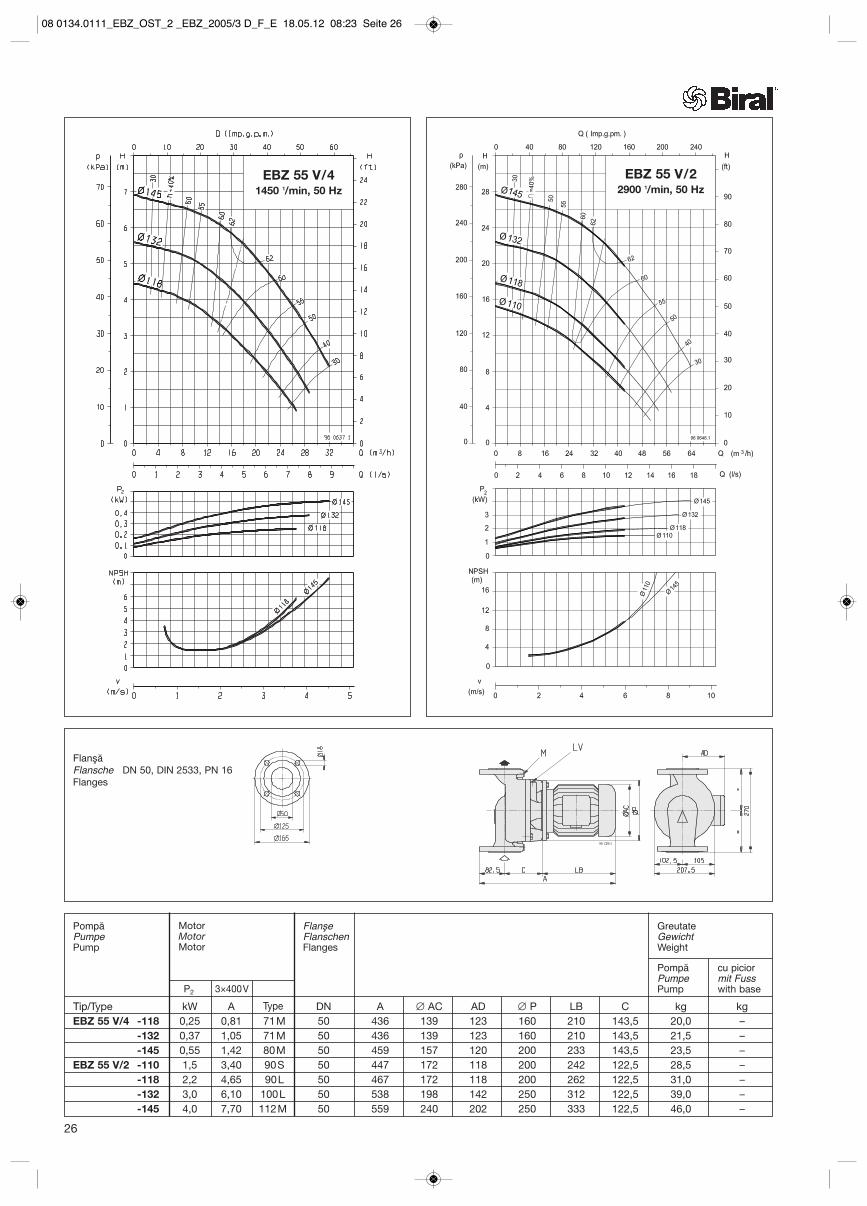
EBZ 55 V/41450 1/min, 50 Hz
26
FlanşăFlansche DN 50, DIN 2533, PN 16Flanges
EBZ 55 V/22900 1/min, 50 Hz
3×400VP2
Tip/Type kW A DN A ∅ AC AD ∅ P LB C kg kgEBZ 55 V/4 -118 0,25 0,81 71M 50 436 139 123 160 210 143,5 20,0 –
-132 0,37 1,05 71M 50 436 139 123 160 210 143,5 21,5 –-145 0,55 1,42 80M 50 459 157 120 200 233 143,5 23,5 –
EBZ 55 V/2 -110 1,5 3,40 90S 50 447 172 118 200 242 122,5 28,5 –-118 2,2 4,65 90L 50 467 172 118 200 262 122,5 31,0 –-132 3,0 6,10 100L 50 538 198 142 250 312 122,5 39,0 –-145 4,0 7,70 112M 50 559 240 202 250 333 122,5 46,0 –
Type
PompăPumpePump
FlanşeFlanschenFlanges
PompăPumpePump
MotorMotorMotor
GreutateGewichtWeight
cu piciormit Fusswith base
08 0134.0111_EBZ_OST_2 _EBZ_2005/3 D_F_E 18.05.12 08:23 Seite 26

EBZ 50 V/41450 1/min, 50 Hz
FlanşăFlansche DN 50, DIN 2533, PN 16Flanges
27
3×400VP2
Tip/Type kW A DN A ∅ AC AD ∅ P LB C kg kgEBZ 50 V/4 -222 2,2 4,9 100L 50 538 196 129 250 313 142,5 58 –
-243 3,0 6,4 100L 50 538 196 129 250 313 142,5 60 –-254 4,0 8,3 112M 50 558 220 142 250 333 142,5 65 –
Type
PompăPumpePump
FlanşeFlanschenFlanges
PompăPumpePump
MotorMotorMotor
GreutateGewichtWeight
cu piciormit Fusswith base
08 0134.0111_EBZ_OST_2 _EBZ_2005/3 D_F_E 18.05.12 08:24 Seite 27

28
FlanşăFlansche DN 65, DIN 2533, PN 16Flanges
EBZ 65 V/41450 1/min, 50 Hz
EBZ 65 V/22900 1/min, 50 Hz
3×400VP2
Tip/Type kW A DN A ∅ AC AD ∅ P LB C kg kg EBZ 65 V/4 -130 0,55 1,42 80M 65 437 157 120 200 233 111,5 31,5 –
-143 0,75 1,86 80M 65 437 157 120 200 233 111,5 33,0 –-158 1,10 2,70 90S 65 485 174 128 200 281 111,5 35,5 –-170 1,50 3,60 90L 65 485 174 128 200 281 111,5 39,0 –
EBZ 65 V/2 -130 4,00 7,70 112M 65 558 240 202 250 333 132,5 54,0 –-143 5,50 10,3 132S 65 599 280 218 300 374 132,5 67,0 –-158 7,50 13,8 132S 65 599 280 218 300 374 132,5 77,0 –
Type
PompăPumpePump
FlanşeFlanschenFlanges
PompăPumpePump
MotorMotorMotor
GreutateGewichtWeight
cu piciormit Fusswith base
08 0134.0111_EBZ_OST_2 _EBZ_2005/3 D_F_E 18.05.12 08:24 Seite 28

FlanşăFlansche DN 65, DIN 2533, PN 16Flanges
29
EBZ 67 V/41450 1/min, 50 Hz
3×400VP2
Tip/Type kW A DN A ∅ AC AD ∅ P LB C kg kg EBZ 67 V/4 -193 2,2 4,9 100 L 65 526 196 129 250 313 115,5 73 –
-216 3,0 6,4 100 L 65 526 196 129 250 313 115,5 75 –-234 4,0 8,3 112M 65 546 220 142 250 333 115,5 80 –-260 5,5 11,4 132S 65 587 259 164 300 374 115,5 94 –
Type
PompăPumpePump
FlanşeFlanschenFlanges
PompăPumpePump
MotorMotorMotor
GreutateGewichtWeight
cu piciormit Fusswith base
08 0134.0111_EBZ_OST_2 _EBZ_2005/3 D_F_E 18.05.12 08:24 Seite 29

30
FlanşăFlansche DN 80, DIN 2533, PN 16Flanges
EBZ 85 V/41450 1/min, 50 Hz
Pompă cu piciorPumpe mit FussExecution with base
3×400VP2
Tip/Type kW A DN A A1 ∅ AC AD ∅ P LB C kg kg EBZ 85 V/4 -148 1,1 2,7 90S 80 509,5 534,5 174 128 200 281 128,5 48,5 50,5
-162 1,5 3,6 90L 80 509,5 534,5 174 128 200 281 128,5 46,0 54,0-176 2,2 4,9 100L 80 541,5 566,5 196 129 250 313 128,5 55,0 63,0-200 3,0 6,4 100L 80 541,5 566,5 196 129 250 313 128,5 57,0 65,0
Type
PompăPumpePump
FlanşeFlanschenFlanges
PompăPumpePump
MotorMotorMotor
GreutateGewichtWeight
cu piciormit Fusswith base
08 0134.0111_EBZ_OST_2 _EBZ_2005/3 D_F_E 18.05.12 08:24 Seite 30

FlanşăFlansche DN 80, DIN 2533, PN 16Flanges
31
EBZ 87 V/41450 1/min, 50 Hz
Pompa ze stopąPompă cu piciorExecution with base
3×400VP2
Tip/Type kW A DN A A1 ∅ AC AD ∅ P LB C kg kg EBZ 87 V/4 -210 3,0 6,4 100 L 80 539 587 196 129 250 313 116 84 94
-225 4,0 8,3 112M 80 559 607 220 142 250 333 116 89 99-245 5,5 11,4 132 S 80 600 648 259 164 300 374 116 103 113-269 7,5 15,1 132M 80 600 648 259 164 300 374 116 114 124
Type
PompăPumpePump
FlanşeFlanschenFlanges
PompăPumpePump
MotorMotorMotor
GreutateGewichtWeight
cu piciormit Fusswith base
08 0134.0111_EBZ_OST_2 _EBZ_2005/3 D_F_E 18.05.12 08:24 Seite 31

32
FlanşăFlansche DN 100, DIN 2533, PN 16Flanges
Pompa ze stopąPompă cu piciorExecution with base
EBZ 100 V/41450 1/min, 50 Hz
3×400VP2
Tip/Type kW A DN A A1 ∅ AC AD ∅ P LB C kg kg EBZ 100 V/4 -158 2,2 4,9 100L 100 562,5 597,5 196 129 250 313 140,5 64 72
-171 3,0 6,4 100L 100 562,5 597,5 196 129 250 313 140,5 66 74-186 4,0 8,3 112M 100 583,5 618,5 240 142 250 333 140,5 71 79-200 5,5 11,4 132 S 100 624,5 659,5 259 164 300 374 140,5 85 93
Type
PompăPumpePump
FlanşeFlanschenFlanges
PompăPumpePump
MotorMotorMotor
GreutateGewichtWeight
cu piciormit Fusswith base
08 0134.0111_EBZ_OST_2 _EBZ_2005/3 D_F_E 18.05.12 08:24 Seite 32

FlanşăFlansche DN 100, DIN 2533, PN 16Flanges
33
Pompă cu piciorPumpe mit FussExecution with base
EBZ 102 V/41450 1/min, 50 Hz
3×400VP2
Tip/Type kW A DN A A1 ∅ AC AD ∅ P LB C kg kg EBZ 102 V/4 -210 3,0 6,4 100L 100 540 587 196 196 250 313 116 93 103
-225 4,0 8,3 112M 100 560 607 220 220 250 333 116 98 108-245 5,5 11,4 132S 100 601 648 259 259 300 374 116 112 122-269 7,5 15,1 132M 100 601 648 259 259 300 374 116 123 133
Type
PompăPumpePump
FlanşeFlanschenFlanges
PompăPumpePump
MotorMotorMotor
GreutateGewichtWeight
cu piciormit Fusswith base
08 0134.0111_EBZ_OST_2 _EBZ_2005/3 D_F_E 18.05.12 08:24 Seite 33
34
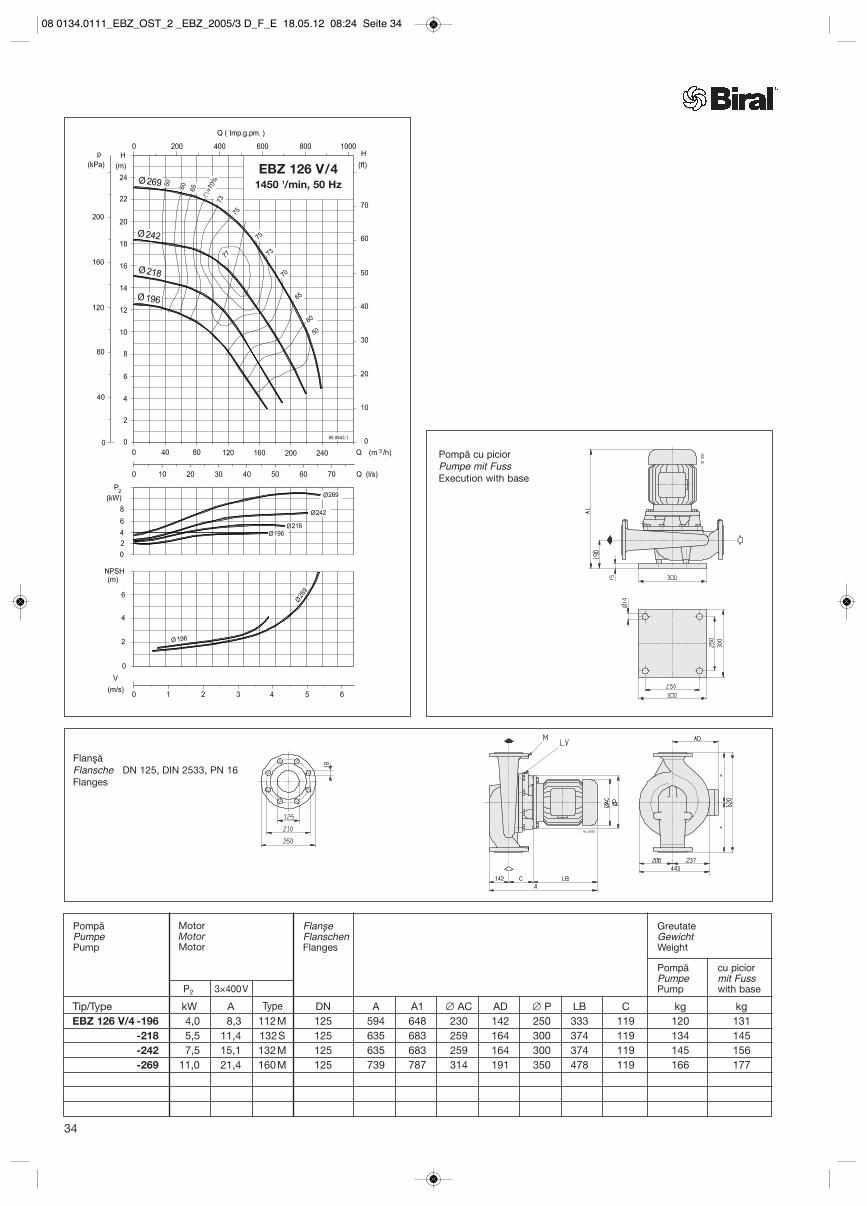
FlanşăFlansche DN 125, DIN 2533, PN 16Flanges
Pompă cu piciorPumpe mit FussExecution with base
EBZ 126 V/41450 1/min, 50 Hz
3×400VP2
Tip/Type kW A DN A A1 ∅ AC AD ∅ P LB C kg kg EBZ 126 V/4 -196 4,0 8,3 112M 125 594 648 230 142 250 333 119 120 131
-218 5,5 11,4 132S 125 635 683 259 164 300 374 119 134 145-242 7,5 15,1 132M 125 635 683 259 164 300 374 119 145 156-269 11,0 21,4 160M 125 739 787 314 191 350 478 119 166 177
Type
PompăPumpePump
FlanşeFlanschenFlanges
PompăPumpePump
MotorMotorMotor
GreutateGewichtWeight
cu piciormit Fusswith base
08 0134.0111_EBZ_OST_2 _EBZ_2005/3 D_F_E 18.05.12 08:24 Seite 34

FlanşăFlansche DN 150, DIN 2533, PN 16Flanges
35
Pompă cu piciorPumpe mit FussExecution with base
EBZ 150 V/41450 1/min, 50 Hz
3×400VP2
Tip/Type kW A DN A A1 ∅ AC AD ∅ P LB C kg kg EBZ 150 V/4 -198 5,5 11,4 132 S 150 660 713 259 164 300 374 124 166 186
-210 7,5 15,1 132M 150 660 713 259 164 300 374 124 177 197-238 11,0 21,4 160M 150 764 817 314 191 350 478 124 198 218-269 18,5 36,0 180M 150 785 838 313 242 350 499 124 256 276
Type
PompăPumpePump
FlanşeFlanschenFlanges
PompăPumpePump
MotorMotorMotor
GreutateGewichtWeight
cu piciormit Fusswith base
08 0134.0111_EBZ_OST_2 _EBZ_2005/3 D_F_E 18.05.12 08:24 Seite 35

36
08 0134.0111_EBZ_OST_2 _EBZ_2005/3 D_F_E 18.05.12 08:24 Seite 36

Pompe Biral InlineBiral-Inline-PumpenBiral Inline Pumps
EBZ-E
Debit – Förderstrom Q
Capacitate – Capacity Q (I.G.P.M.)
Tota
l hea
d –
Înăl
ţime
tota
lă
H (f
eet)
Înăl
ţime
de p
ompa
re–
Förd
erhö
heH
37
EBZ-E1740 1/min
1450 1/min2900 1/min
(H)
Caracteristici conform EN 9906 K2Kennlinien nach EN 9906 K2Characteristic curves according to EN 9906 K2
08 0134.0111_EBZ_OST_2 _EBZ_2005/3 D_F_E 18.05.12 08:24 Seite 37

100%
p konst.1
p prop.
2
NPSH 100%
NPSH(m)
1
2
100%
0
1
2
3
4
5
6
7
0 2 4 6 8 10 12 14 16 180
10
20
30
40
50
60
70
p(kPa)
H(m)
Q (m³/h)0
22
4
46
6
8
10
12
14
16
18
20
22
H(ft)
0 10 20 30 40 50 60 70
Q (lmp.g.p.m.)
0 1 2 3 4 5 Q (l/s)
P1
(kW)
0.5
0.4
0.3
0.2
0.1
0
0 1 2 3 4
v(m/s)
96 0665.1
EBZ-E 45 V/4-120 H1740 1/min, 50 Hz
FlanşăFlansche DN 40, DIN 2533, PN 16Flanges
38
PompăPumpePump
FlanşeFlanschenFlanges
PompăPumpePump
MotorMotorMotor
GreutateGewichtWeight
U I TypeP2
cu piciormit Fusswith base
Tip/Type [kW] [V] [A] DN A ∅ AC AD AE B LB kg kgEBZ-E 45 V/4-120 H 1,1 3×400V 3,2 90S 40 502 178 167 264 106 321 41 –
08 0134.0111_EBZ_OST_2 _EBZ_2005/3 D_F_E 18.05.12 08:24 Seite 38
100%
p konst.1
p prop.
2
NPSH 100%
NPSH(m)
1
2
100%
0
2
4
6
8
10
0 4 8 18120
p(kPa)
H(m)
Q (m³/h)0
4
85
10
15
20
25
30
H(ft)
0 20 40 70
Q (lmp.g.p.m.)
0 2 Q (l/s)P1
(kW)
0.2
0
0 1 2 3 4
v(m/s)
96 0654.1
12
14
1 3
0.4
5
80
16016
18
35
40
45
20 26
4 5
0.6
90 110
6 7
0.8
1
20
20
40
60
100
120
140
180
50
55
60
65
1.2
1.4
6
10 30 50 60 80 100
2 6 10 14 16 22 24 28 30
8
1.6
7
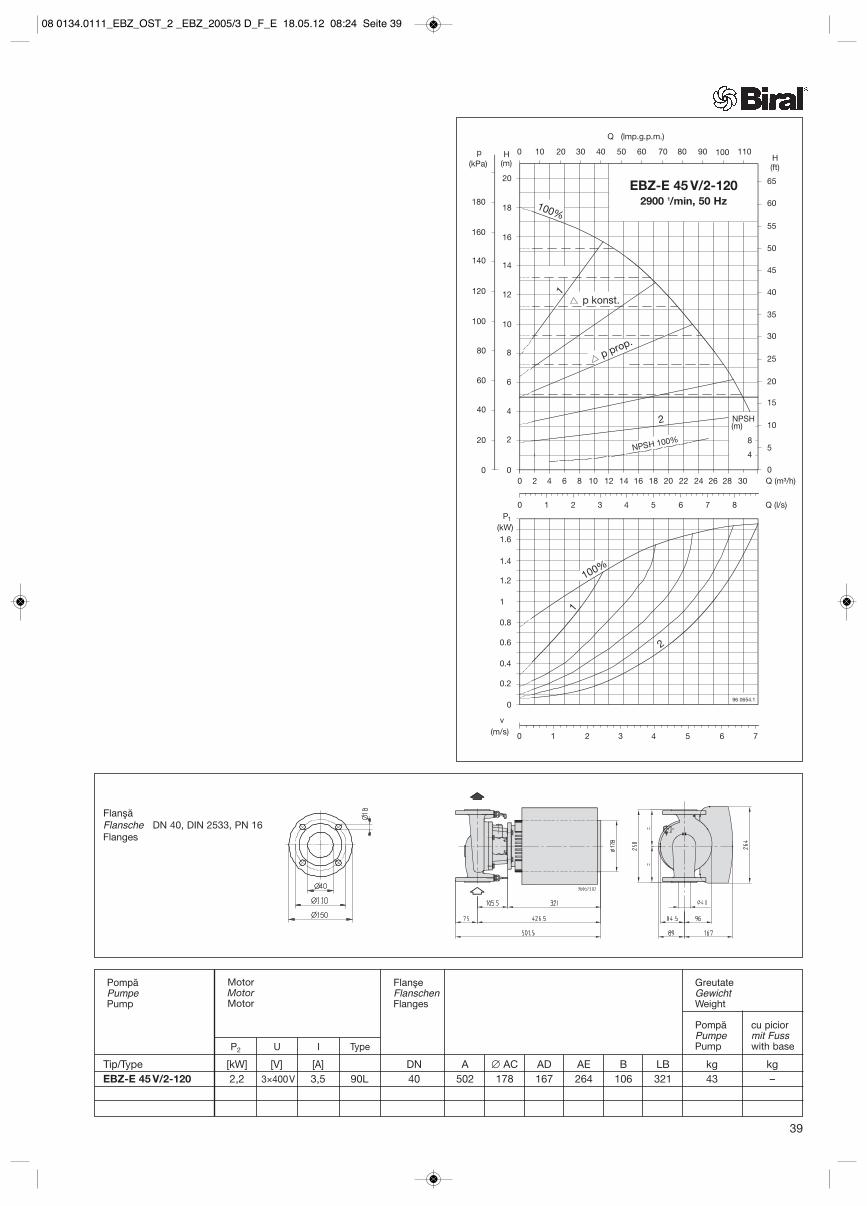
EBZ-E 45 V/2-1202900 1/min, 50 Hz
FlanşăFlansche DN 40, DIN 2533, PN 16Flanges
39
U I TypeP2
Tip/Type [kW] [V] [A] DN A ∅ AC AD AE B LB kg kgEBZ-E 45 V/2-120 2,2 3×400V 3,5 90L 40 502 178 167 264 106 321 43 –
PompăPumpePump
FlanşeFlanschenFlanges
PompăPumpePump
MotorMotorMotor
GreutateGewichtWeight
cu piciormit Fusswith base
08 0134.0111_EBZ_OST_2 _EBZ_2005/3 D_F_E 18.05.12 08:24 Seite 39

100%
p konst.
1
p prop.
2
NPSH 100%
NPSH(m)
1
2
100%
0
1
2
3
4
5
6
7
0 4 8 12 16 20 24 28 32 360
20
40
60
80
100
p(kPa)
H(m)
Q (m³/h)0
2
4
56
10
15
20
25
30
35
H(ft)
0 20 40 60 80 100 120 140
Q (lmp.g.p.m.)
0 2 4 6 8 10 Q (l/s)
P1
(kW)
1.0
0.8
0.6
0.4
0.2
0
0 1 2 3 4
v(m/s)
96 0667.1
8
9
10
8
40
1 3 5 7 9 11
1.2
5
EBZ-E 55 V/4-145 H1740 1/min, 50 Hz
FlanşăFlansche DN 50, DIN 2533, PN 16Flanges
40
U I TypeP2
Tip/Type [kW] [V] [A] DN A ∅ AC AD AE B LB kg kgEBZ-E 55 V/4-145 H 1,1 3×400V 3,2 90S 50 547 178 167 264 144 321 38 –
PompăPumpePump
FlanşeFlanschenFlanges
PompăPumpePump
MotorMotorMotor
GreutateGewichtWeight
cu piciormit Fusswith base
08 0134.0111_EBZ_OST_2 _EBZ_2005/3 D_F_E 18.05.12 08:24 Seite 40

EBZ-E 55 V/2-1452900 1/min, 50 Hz
EBZ-E 55 V/2-1182900 1/min, 50 Hz
FlanşăFlansche DN 50, DIN 2533, PN 16Flanges
41
U I TypeP2
Tip/Type [kW] [V] [A] DN A ∅ AC AD AE B LB kg kgEBZ-E 55 V/2-118 2,2 3×400V 3,5 90L 50 526 178 167 264 123 321 47 –EBZ-E 55 V/2-145 4,0 3×400V 9,0 112M 50 577 220 188 290 123 372 65 –
PompăPumpePump
FlanşeFlanschenFlanges
PompăPumpePump
MotorMotorMotor
GreutateGewichtWeight
cu piciormit Fusswith base
08 0134.0111_EBZ_OST_2 _EBZ_2005/3 D_F_E 18.05.12 08:24 Seite 41

100%
p konst.
1
p prop.
2
NPSH 100%
NPSH(m)
1
2
100%
0
1
2
3
4
5
6
7
0 10 20 30 40 50 600
20
40
60
80
90
p(kPa)
H(m)
Q (m³/h)0
2
4
56
10
15
20
25
30
H(ft)
0 50 100 150 200 250
Q (lmp.g.p.m.)
0 10 Q (l/s)
P1
(kW)
1.2
0.8
0.4
0
0 1 2 3 4
v(m/s)
96 0668.1
8
9
10
8
5 15
1.6
5
10
30
50
70
EBZ-E 65 V/4-1701450 1/min, 50 Hz
FlanşăFlansche DN 65, DIN 2533, PN 16Flanges
42
U I TypeP2
Tip/Type [kW] [V] [A] DN A ∅ AC AD AE B LB kg kgEBZ-E 65 V/4-170 1,5 3×400V 4,2 90L 65 525 178 167 164 112 321 54 –
PompăPumpePump
FlanşeFlanschenFlanges
PompăPumpePump
MotorMotorMotor
GreutateGewichtWeight
cu piciormit Fusswith base
08 0134.0111_EBZ_OST_2 _EBZ_2005/3 D_F_E 18.05.12 08:24 Seite 42

100%
p konst.
1
p prop.
2
NPSH 100%
NPSH(m)
1
2
100%
0
5
10
15
20
0 20 600
p(kPa)
H(m)
Q (m³/h)0
10
2020
40
H(ft)
0 100 200
Q (lmp.g.p.m.)
0 Q (l/s)P1
(kW)
0
0 2 4 6
v(m/s)
96 0672.1
25
2
8
150
30030
35
60
80
80
10
300
20
4
50
100
200
250
350
100
120
6
40
30
8
EBZ-E 65 V/2-1582900 1/min, 50 Hz
EBZ-E 65 V/2-1302900 1/min, 50 Hz
FlanşăFlansche DN 65, DIN 2533, PN 16Flanges
43
U I TypeP2
Tip/Type [kW] [V] [A] DN A ∅ AC AD AE B LB kg kgEBZ-E 65 V/2-130 4,0 3×400V 9,0 112M 65 597 220 188 290 133 372 71 –EBZ-E 65 V/2-158 7,5 3×400V 16,0 132S 65 616 220 188 290 133 391 82 –
PompăPumpePump
FlanşeFlanschenFlanges
PompăPumpePump
MotorMotorMotor
GreutateGewichtWeight
cu piciormit Fusswith base
08 0134.0111_EBZ_OST_2 _EBZ_2005/3 D_F_E 18.05.12 08:24 Seite 43

U I TypeP2
Tip/Type [kW] [V] [A] DN A ∅ AC AD AE B LB kg kgEBZ-E 85 V/4-176 2,2 3×400V 4,6 100L 80 564 198 177 264 129 335 69 79EBZ-E 85 V/4-200 3,0 3×400V 7,2 100L 80 564 198 177 264 129 335 71 81
100%
p konst.
1
p prop.
2
NPSH 100%
NPSH(m)
1
2
100%
0
1
2
3
4
5
6
7
0 10 20 30 40 50 600
p(kPa)
H(m)
Q (m³/h)0
510
515
10
15
20
25
30
H(ft)
0 100 200 300
Q (lmp.g.p.m.)
0 10 Q (l/s)
P1
(kW)
1.5
1
0.5
0
0 1 2 3 4
v(m/s)
96 0669.1
8
9
10
5 15
2
5
50
100
11
12
13
35
40
45
70 80 90
20 25
2.5
3
3.5
EBZ-E 85 V/4-2001450 1/min, 50 Hz
100%
p konst.
1
p prop.
2
NPSH 100%
NPSH(m)
1
2
100%
0
1
2
3
4
5
6
7
0 10 20 30 40 50 600
p H(m)
Q (m³/h)0
510
515
10
15
20
25
30
H(ft)
0 100 200 300
Q (lmp.g.p.m.)
0 10 Q (l/s)
P1
(kW)
1.5
1
0.5
0
0 1 2 3 4
v(m/s)
96 1346.0
8
9
15
2
5
50
10
35
70 80 90
20 25
2.5
100
305
400
40
90
80
70
60
10
20
30
6
EBZ-E 85 V/4-1761450 1/min, 50 Hz
FlanşăFlansche DN 80, DIN 2533, PN 16Flanges
44
PompăPumpePump
FlanşeFlanschenFlanges
PompăPumpePump
MotorMotorMotor
GreutateGewichtWeight
cu piciormit Fusswith base
08 0134.0111_EBZ_OST_2 _EBZ_2005/3 D_F_E 18.05.12 08:24 Seite 44

100%
p konst.
1
p prop.
2
NPSH 100%
NPSH(m)
1
2
100%
0
2
4
6
8
10
0 20 40 60 800
p(kPa)
H(m)
Q (m³/h)0
5
105
15 10
15
20
25
30
H(ft)
0 100 200 300
Q (lmp.g.p.m.)
0 10 Q (l/s)
P1
(kW)
3
2
1
0
0 1 2 3 4
v(m/s)
96 0666.1
12
14
16
5 15
4
5
100
140
18
20
35
40
45
100 120
20 25
5
6
20
40
60
80
120
160
180
200
400 500
50
55
60
65
20
30 35
6 7
EBZ-E 85 V/4-200 H1740 1/min, 50 Hz
EBZ-E 85 V/4-176 H1740 1/min, 50 Hz
FlanşăFlansche DN 80, DIN 2533, PN 16Flanges
U I TypeP2
Tip/Type [kW] [V] [A] DN A ∅ AC AD AE B LB kg kgEBZ-E 85 V/4-176 H 4,0 3×400V 9,0 112M 80 601 220 188 290 129 372 83 93EBZ-E 85 V/4-200 H 5,5 3×400V 11,8 132M 80 620 220 188 290 129 391 87 97
45
PompăPumpePump
FlanşeFlanschenFlanges
PompăPumpePump
MotorMotorMotor
GreutateGewichtWeight
cu piciormit Fusswith base
08 0134.0111_EBZ_OST_2 _EBZ_2005/3 D_F_E 18.05.12 08:24 Seite 45

100%
p konst.
1
p prop.
2
NPSH 100%
NPSH(m)
1 2
100%
0
1
2
3
4
5
6
7
0 20 40 80600
p(kPa)
H(m)
Q (m³/h)0
510
515
10
15
20
25
30
H(ft)
0 100 200 300
Q (lmp.g.p.m.)
0 10 Q (l/s)
P1
(kW)
1.5
1
0.5
0
0 1 2 3 4
v(m/s)
96 0670.1
8
9
10
5 15
2
5
50
100
11
12
13
35
40
45
100 120 140
20 25
2.5
3
3.5
400 500
30 35 40
4
4.5
5
EBZ-E 100 V/4-1861450 1/min, 50 Hz
46
100%
p konst.
1
p prop.
2
NPSH(m)
1
2
100%
0
1
2
3
4
5
6
7
0
p(kPa)
H(m)
05
10
5
15
10
15
20
25
30
H(ft)
P1
(kW)
1.5
1
0.5
096 1452.0
8
9
2
50
10010
35
2.5
40
90
80
70
60
10
20
30
0 20 40 8060
0 105 15
100 120 140
20 25 30 35 40
0 100 200 300
Q (lmp.g.p.m.)
400 500
0 1 2 3 4 5
NPSH 100%
Q (m³/h)
Q (l/s)
v(m/s)
EBZ-E 100 V/4-1711450 1/min, 50 Hz
FlanşăFlansche DN 100, PN 16Flanges
U I TypeP2
Tip/Type [kW] [V] [A] DN A ∅ AC AD AE B LB kg kgEBZ-E 100 V/4-171 3,0 3×400V 7,2 100L 100/16 586 198 177 264 129 335 77 87EBZ-E 100 V/4-186 4,0 3×400V 9,0 112M 100 623 220 188 290 141 372 90 100EBZ-E 100 V/4-200 5,5 3×400V 11,8 132 S 100 642 220 188 290 141 391 95 105
PompăPumpePump
FlanşeFlanschenFlanges
PompăPumpePump
MotorMotorMotor
GreutateGewichtWeight
cu piciormit Fusswith base
EBZ-E 100 V/4-171disponibilă şi cu flanşă PN 6
EBZ-E 100 V/4-171auch mit Flansch PN 6 erhältlich
EBZ-E 100 V/4-171Also available with flange, PN 6
170
100
210
18
PN 6 PN 16
08 0134.0111_EBZ_OST_2 _EBZ_2005/3 D_F_E 18.05.12 08:24 Seite 46

47
100%
p konst.
1
p prop.
2
NPSH 100%
NPSH(m)
1
100%
0
1
2
3
4
5
6
7
0 20 40 80600
p(kPa)
H(m)
Q (m³/h)0
510
515
10
15
20
25
30
H(ft)
0 100 200 300
Q (lmp.g.p.m.)
0 10 Q (l/s)
P1
(kW)
1.5
1
0.5
0
0 1 2 3 4
v(m/s)
96 1279
8
9
10
5 15
2
5
50
100
11
12
13
35
40
45
100 120 140
20 25
2.5
3
3.5
400 500
30 35 40
4
4.5
5
2
EBZ-E 100 V/4-2001450 1/min, 50 Hz
FlanşăFlansche DN 100, DIN 2533, PN 16Flanges
EBZ-E 102 V/4-2691450 1/min, 50 Hz
U I TypeP2
Tip/Type [kW] [V] [A] DN A ∅ AC AD AE B LB kg kgEBZ-E 102 V/4-269 7,5 3×400V 15,5 132S 100 676 258 359 269 116 449 180 190
PompăPumpePump
FlanşeFlanschenFlanges
PompăPumpePump
MotorMotorMotor
GreutateGewichtWeight
cu piciormit Fusswith base
08 0134.0111_EBZ_OST_2 _EBZ_2005/3 D_F_E 18.05.12 08:24 Seite 47

EBZ-E 126 V/4-2181450 1/min, 50 Hz
FlanşăFlansche DN 125, DIN 2533, PN 16Flanges
48
U I TypeP2
Tip/Type [kW] [V] [A] DN A ∅ AC AD AE B LB kg kgEBZ-E 126 V/4-218 5,5 3×400V 11,8 132S 125 652 220 188 290 119 391 – 147
PompăPumpePump
FlanşeFlanschenFlanges
PompăPumpePump
MotorMotorMotor
GreutateGewichtWeight
cu piciormit Fusswith base
08 0134.0111_EBZ_OST_2 _EBZ_2005/3 D_F_E 18.05.12 08:24 Seite 48

49
FlanşăFlansche DN 125, DIN 2533, PN 16Flanges
EBZ-E 126 V/4-2691450 1/min, 50 Hz
EBZ-E 126 V/4-2421450 1/min, 50 Hz
U I TypeP2
Tip/Type [kW] [V] [A] DN A ∅ AC AD AE B LB kg kgEBZ-E 126 V/4-242 7,5 3×400V 15,5 132S 125 710 258 359 269 119 449 – 210EBZ-E 126 V/4-269 11,0 3×400V 21,8 160M 125 710 258 359 269 119 449 – 221
PompăPumpePump
FlanşeFlanschenFlanges
PompăPumpePump
MotorMotorMotor
GreutateGewichtWeight
cu piciormit Fusswith base
08 0134.0111_EBZ_OST_2 _EBZ_2005/3 D_F_E 18.05.12 08:24 Seite 49

0
EBZ-E 150 V/4-2101450 1/min, 50 Hz
FlanşăFlansche DN 150, DIN 2533, PN 16Flanges
50
U I TypeP2
Tip/Type [kW] [V] [A] DN A ∅ AC AD AE B LB kg kgEBZ-E 150 V/4-210 7,5 3×400V 15,5 132S 150 735 258 359 258 124 449 – 255
PompăPumpePump
FlanşeFlanschenFlanges
PompăPumpePump
MotorMotorMotor
GreutateGewichtWeight
cu piciormit Fusswith base
08 0134.0111_EBZ_OST_2 _EBZ_2005/3 D_F_E 18.05.12 08:24 Seite 50

51
FlanşăFlansche DN 150, DIN 2533, PN 16Flanges
EBZ-E 150 V/4-2691450 1/min, 50 Hz
EBZ-E 150 V/4-2381450 1/min, 50 Hz
U I TypeP2
Tip/Type [kW] [V] [A] DN A ∅ AC AD AE B LB kg kgEBZ-E 150 V/4-238 11,0 3×400V 21,5 160M 150 735 258 355 258 124 449 – 263EBZ-E 150 V/4-269 18,5 3×400V 36,5 180M 150 785 313 377 313 124 449 – 320
PompăPumpePump
FlanşeFlanschenFlanges
PompăPumpePump
MotorMotorMotor
GreutateGewichtWeight
cu piciormit Fusswith base
08 0134.0111_EBZ_OST_2 _EBZ_2005/3 D_F_E 18.05.12 08:24 Seite 51

EBZ-E Inline cu convertizor de frecvenţă
ConfiguraţieDate detaliate pentru comandarea pompelor EBZ-E
Obiectiv:
Adresa:
Locaţia:
Persoana de contact:
Client:
Strada:
Locaţia:
Persoana de contact:
Telefon:
Nr. comandă Biral:
Pompa EBZ-E:
În special:
Configuraţie:
Reglarea setărilor, bornele 4-6
cu tastele de comandă
Semnalul valorii nominale extern 0 .. 10 V
Semnalul valorii nominale extern 0 .. 20 mA
Semnalul valorii nominale extern 4 .. 20 mA
Măsurarea valorii efective, bornele 7-8
Cu transmiţătorul de presiune diferenţială
Semnalul valorii reale extern 0 .. 10 V
Semnalul valorii reale extern 0 .. 20 mA
Semnalul valorii reale extern 4 .. 20 mA
Reglarea cu regulatorul PI intern al pompelorProporţional (vezi diagrama pompelor)
Constant (vezi diagrama pompelor)
Debit (m3/h):
Înălţimea de pompare (kPa/m):
Înălţimea nominală de pompare (kPa/m):
Setarea tastelor
fără modificarea configuraţieiSetare din fabrică: 1, A, F, L, U, X
Reglarea cu regulatorul PI intern al pompelorPompa se reglează independent
Reglarea valorii nominale, bornele 4-6
Semnalul valorii nominale extern 0 .. 10 V
Semnalul valorii nominale extern 0 .. 20 mA
Semnalul valorii nominale extern 4 .. 20 mA
Funcţia reglării digitale, bornele 1+3
Turaţia minimă (de ex. scădere noaptea)
Turaţia maximă
Resetarea alarmei (Buton de resetare montat local pe instalaţie, liber de potenţial)
Funcţia reglării digitale, bornele 1+3
Turaţia minimă (de ex. scădere noaptea)
Turaţia maximă
Resetarea alarmei (Buton de resetare montat local pe instalaţie, liber de potenţial)
Funcţia contactului de releu, C-NO-NCContact normal închis: C-NC; contact normal deschis: C-NOMesaj de avarie: Contactul închide dacă pompa este sub tensiune şi survine o avarie.
Pregătit: Contactul închide dacă pompa este sub tensiune şi nu există o avarie
Funcţionare: Contactul închide dacă pompa funcţionează
Resetarea alarmei prin deschiderea contactelor de pornire la bornele 2, 3Oprire + alarmă în cazul valorii nominale eronateOprire + alarmă în cazul erorii la senzor (doar pentru semnal de 4-20 mA)
Pe fiecare câmp este posibilă numai o setare
Funcţia contactului de releu, C-NO-NCContact normal închis: C-NC; contact normal deschis: C-NOMesaj de avarie: Contactul închide dacă pompa este sub tensiune
Pregătit: Contactul închide dacă pompa este sub tensiune şi nu există o avarie
Funcţionare: Contactul închide dacă motorul se roteşte
Resetarea alarmei prin deschiderea contactelor de pornire la bornele 2, 3
Pe fiecare câmp este posibilă numai o setare
Atenţie:La toate tipurile de pompe, care sunt configurate înaintea livrării, termenul de livrare este valabil numai după ce fişa de configuraţie semnată ajunge la sediul Biral AG (CH).Modificările ulterioare ale configuraţiei se pot efectua numai de către unitatea service Biral.
Reglare cu regulator extern(Tastele de comandă de pe pompă sunt inactive)Operatorul trebuie să aibă posibilitatea de reglare.de ex. sistemul de comandă SPS sau HLK cu intare/ieşire analogică
A
1
C
D
E
U
V
W
X
Y
Z
X
Y
Z
F
H
I
K
L
M
2
P
Q
R
U
V
W
Locaţia:
Data:
Semnătura:
fără modificarea configuraţieiSetare din fabrică: 2, P, U, X
09 2400.4010_02
52
08 0134.0111_EBZ_OST_2 _EBZ_2005/3 D_F_E 18.05.12 08:24 Seite 52

53
09 2400.4010_02
Inline-EBZ-E mit stufenloser Drehzahlregelung
KonfigurationDetailangaben zur Bestellung von EBZ-E-Pumpen
Anlage:
Strasse:
Ort:
Bezugsperson:
Besteller:
Strasse:
Ort:
Sachbearbeiter/in:
Telefon:
Biral Auftrag Nr.
Pumpe EBZ-E:
Besonderes:
Konfiguration:
Sollwert-Einstellung, Klemmen 4-6
mit Bedientasten
Sollwertsignal extern 0 .. 10 V
Sollwertsignal extern 0 .. 20 mA
Sollwertsignal extern 4 .. 20 mA
Istwert-Messung, Klemmen 7-8
Mit angebautem Differenzdruck-Transmitter
Istwertsignal extern 0 .. 10 V
Istwertsignal extern 0 .. 20 mA
Istwertsignal extern 4 .. 20 mA
Regulierung mit Pumpen-internem PI-ReglerProportional (siehe Pumpendiagramm)
Konstant (siehe Pumpendiagramm)
Fördermenge (m3/h):
Förderhöhe (kPa/m):
Soll-Förderhöhe (kPa/m):
Tastenstellung
ohne KonfigurationsänderungEinstellung bei Auslieferung: 1, A, F, L, U, X
Regulierung mit Pumpen-internem PI-ReglerDie Pumpe regelt sich selbst
Sollwert-Einstellung, Klemmen 4-6
Sollwertsignal extern 0 .. 10 V
Sollwertsignal extern 0 .. 20 mA
Sollwertsignal extern 4 .. 20 mA
Funktion Digitalregelung, Klemmen 1+3
Minimal-Drehzahl (z. B. Nachtabsenkung)
Maximal-Drehzahl
Alarmrückstellung (Bauseits auf Anlage angebauter Resettaster, potentialfrei)
Funktion Digitalregelung, Klemmen 1+3
Minimal-Drehzahl (z. B. Nachtabsenkung)
Maximal-Drehzahl
Alarmrückstellung (Bauseits auf Anlage angebauter Resettaster, potentialfrei)
Funktion Relaiskontakt, C-NO-NCÖffner: C-NC; Schliesser: C-NOStörmeldung: Kontakt schliesst, wenn Pumpe Spannung hat und eine Störung auftritt.
Bereit: Kontakt schliesst, wenn Pumpe Spannung hat und keine Störung besteht
Betrieb: Kontakt schliesst, wenn Motor dreht
Alarmrückstellung durch Öffnen des Startkontakts Klemmen 2, 3Stop + Alarm bei SollwertfehlerStop + Alarm bei Sensorfehler (nur 4-20 mA Signal)
Pro Feld nur eine Einstellung möglich
Funktion Relaiskontakt, C-NO-NCÖffner: C-NC; Schliesser: C-NOStörmeldung: Kontakt schliesst, wenn Pumpe Spannung hat und eine Störung auftritt.
Bereit: Kontakt schliesst, wenn Pumpe Spannung hat und keine Störung besteht
Betrieb: Kontakt schliesst, wenn Motor dreht
Alarmrückstellung durch Öffnen des Startkontakts Klemmen 2, 3
Pro Feld nur eine Einstellung möglich
Achtung:Bei allen Pumpentypen, die vor Auslieferung konfiguriert werden,gilt die Lieferfrist erst, wenn sich das unterschriebeneKonfigurationsblatt im Hause Biral AG (CH) befindet.Nachträgliche Konfigurationsänderungen können nur vom Biral-Service vorgenommen werden.
Regulierung mit externem Regler(Bedientasten auf Pumpe sind inaktiv)Der Betreiber muss die Regelungsmöglichkeit haben.z. B. SPS oder HLK-Steuerung mit Analog-Ein-/Ausgang
A
1
C
D
E
U
V
W
X
Y
Z
X
Y
Z
F
H
I
K
L
M
2
P
Q
R
U
V
W
Ort:
Datum:
Unterschrift:
ohne KonfigurationsänderungEinstellung bei Auslieferung: 2, P, U, X
08 0134.0111_EBZ_OST_2 _EBZ_2005/3 D_F_E 18.05.12 08:24 Seite 53

Inline EBZ-E with integrated frequency converter
ConfigurationDetails of EBZ-E order
Object:
Street:
Place:
Person resp.:
Purchaser:
Address:
Place:
Techn. person in charge:
Phone:
Biral order number:
Pump EBZ-E:
Special:
Configuration:
Setting adjustment, binding post 4-6
with control keys
with external set point-signal 0 .. 10 V
with external set point-signal 0 .. 20 mA
with external set point-signal 4 .. 20 mA
Instantaneous value measurement, binding post 7-8
differential pressure transmitter fitted 4 .. 20 mA
with external actual value signal from 0 .. 10 V
with external actual value signal from 0 .. 20 mA
with external actual value signal from 4 .. 20 mA
Regulated with pump-internal PI-controllerproportional direct (pls. refer to pump diagram)
constant direct (pls. refer to pump diagram
Flow (m3/h):
Head (kPa/m):
Head set-point in (kPa/m):
Pushbutton position
without change of configurationSetting when supplied 1, A, F, L, U, X
Regulated with pump-internal PI-regulatorThe pump regulates itself
Set-point adjustment, binding post 4-6
with external set point-signal 0 .. 10 V
with external set point-signal 0 .. 20 mA
with external set point-signal 4 .. 20 mA
Function digital entry, binding post 1+3
Minimum speed (e.g. reduction during the night)
Maximum speed
Alarm reset(potential-free reset button integrated in the building)
Function digital entry, binding post 1+3
Minimum speed (e.g. reduction during the night)
Maximum speed
alarm reset(potential-free reset button integrated in the building)
Function relays contact, C-NO-NCOpener: C-NC, Closer: C-NOfault message: contact closes,if pump has voltage and obstruction present
Ready: contact closes,if pump has voltage and no obstruction present
Operation: contact closes, if pump is running
Alarm reset by opening of start contacts,binding post 2-3stop + alarm if set-point errorstop + alarm if sensor error (only if 20 mA signal)
Only one setting possible per field
Function relay contact, C-NO-NCOpener: C-NC, Closer: C-NOFault message: contact closes,if pump has voltage
Ready: contact closes,if pump has voltage and no obstruction present
Operation: contact closes, if motor rotates
Alarm reset by opening of start contacts,binding post 2-3
Only one setting possible per field
Note:For each pump programmed before delivery,the delivery time starts the day this configuration sheet is received.Change of configuration must only be performedby Biral service technician.
Regulated with external controller(Control keys on pump are inactive)The client must have control possibilitye.g. SPS-control with analogue On/Off exit (output?)Heating-air-conditioning control with analogue On/Off exit, etc.
A
1
C
D
E
U
V
W
X
Y
Z
X
Y
Z
F
H
I
K
L
M
2
P
Q
R
U
V
W
Place:
Date:
Signature:
09 2400.4011_02
without change of configurationSetting when supplied 2, P, U, X
54
08 0134.0111_EBZ_OST_2 _EBZ_2005/3 D_F_E 18.05.12 08:24 Seite 54

08 0134.0111_EBZ_OST_2 _EBZ_2005/3 D_F_E 18.05.12 08:24 Seite 55

Biral AG Münsingen, sediul central din Elveţia
Nr.
03/1
2 0
8 01
34.0
111_
00 O
st_2
Biral AGSüdstrasse 10CH-3110 MünsingenT +41 (0) 31 720 90 00F +41 (0) 31 720 94 42E-Mail: [email protected]
Biral GmbHPräzisionspumpenFreiherr-vom-Stein-Weg 15 D-72108 Rottenburg am NeckarT +49 (0) 7472 16 33 0F +49 (0) 7472 16 34 0E-Mail: [email protected]
Biral Pompen B.VPrinterweg 13 3821 APPostbus 2650 3800 GENL-AmersfoortT +31 (0) 33 455 94 44F +31 (0) 33 455 96 10E-Mail: [email protected]
08 0134.0111_EBZ_OST_2 _EBZ_2005/3 D_F_E 18.05.12 08:24 Seite 56