Injection Moldingweb.mit.edu/.../lectures/lec8-injection-molding-2018.pdfCompounding - extrusion An...
59
Injection Molding 2.810 T. Gutowski D. Roylance 1
Transcript of Injection Moldingweb.mit.edu/.../lectures/lec8-injection-molding-2018.pdfCompounding - extrusion An...
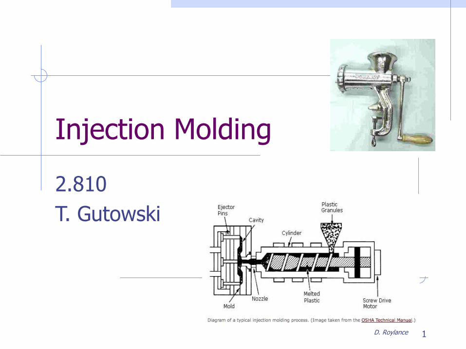
Injection Molding
2.810
T. Gutowski
D. Roylance 1
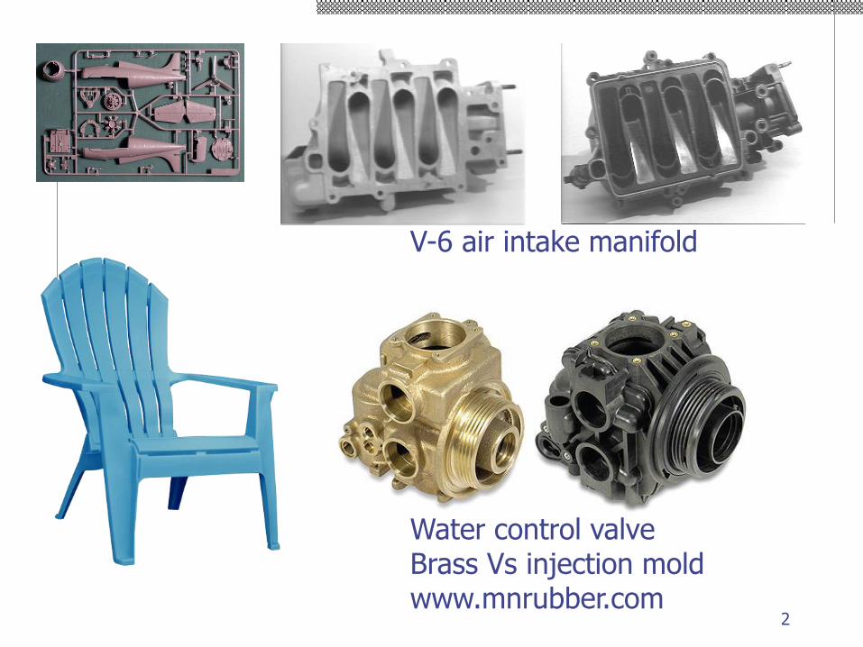
V-6 air intake manifold
Water control valveBrass Vs injection moldwww.mnrubber.com
2
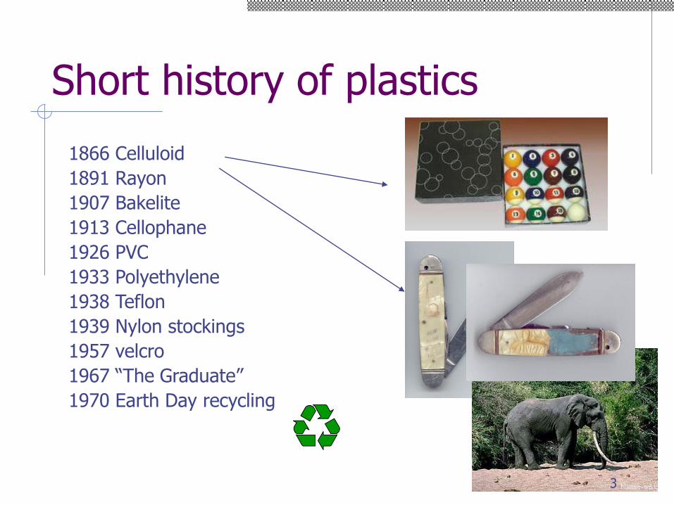
Short history of plastics
1866 Celluloid
1891 Rayon
1907 Bakelite
1913 Cellophane
1926 PVC
1933 Polyethylene
1938 Teflon
1939 Nylon stockings
1957 velcro
1967 “The Graduate”
1970 Earth Day recycling
3
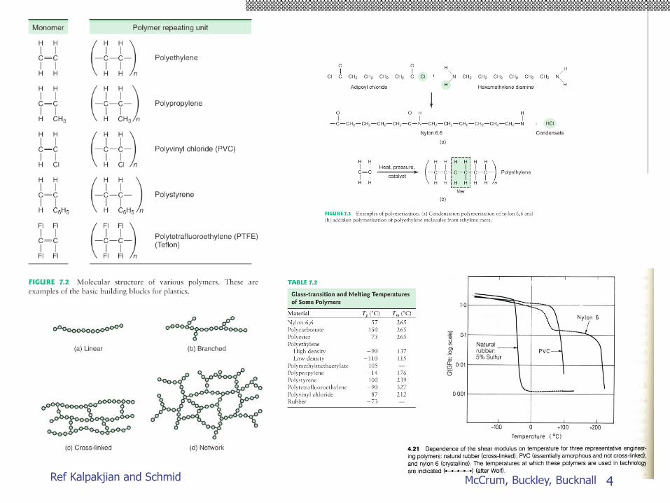
Ref Kalpakjian and Schmid McCrum, Buckley, Bucknall 4
Outline
Basic operation
Cycle time and heat transfer
Flow and solidification
Part design
Tooling
New developments
Environment
5
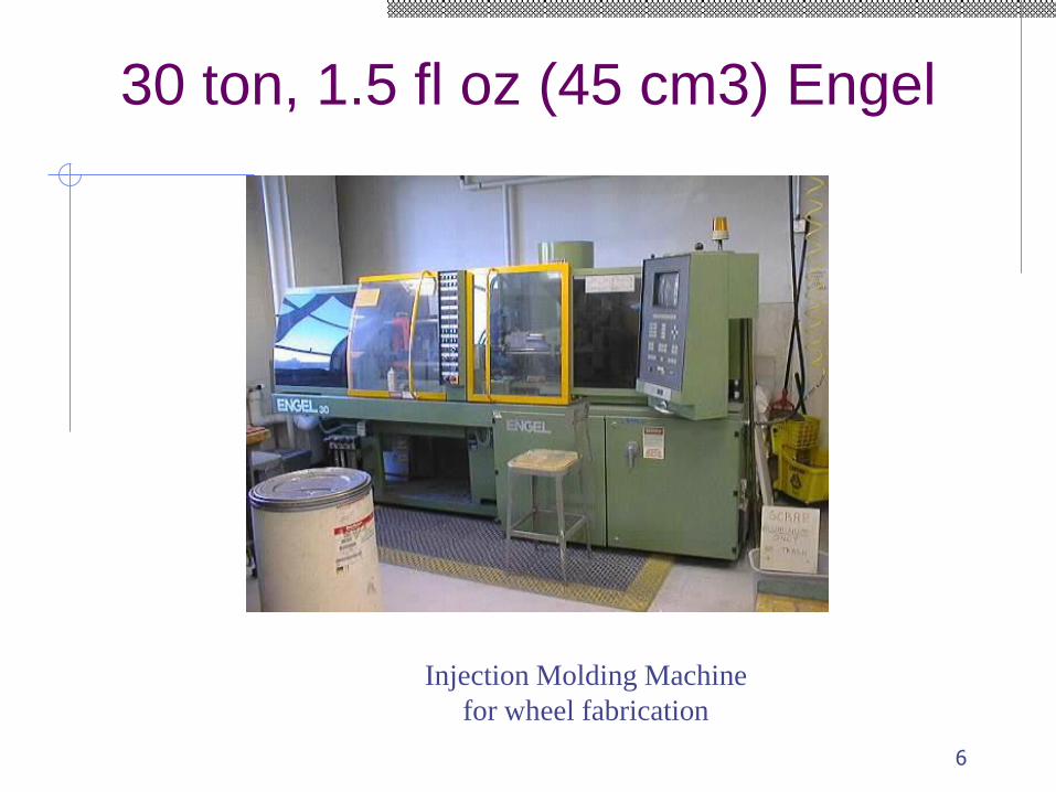
30 ton, 1.5 fl oz (45 cm3) Engel
Injection Molding Machine
for wheel fabrication
6
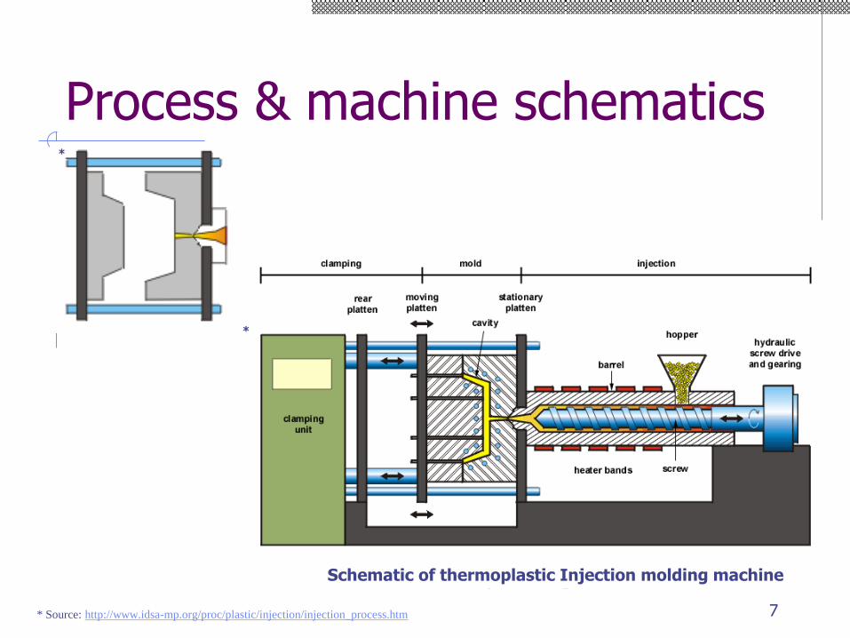
Process & machine schematics*
* Source: http://www.idsa-mp.org/proc/plastic/injection/injection_process.htm
*
Schematic of thermoplastic Injection molding machine
7
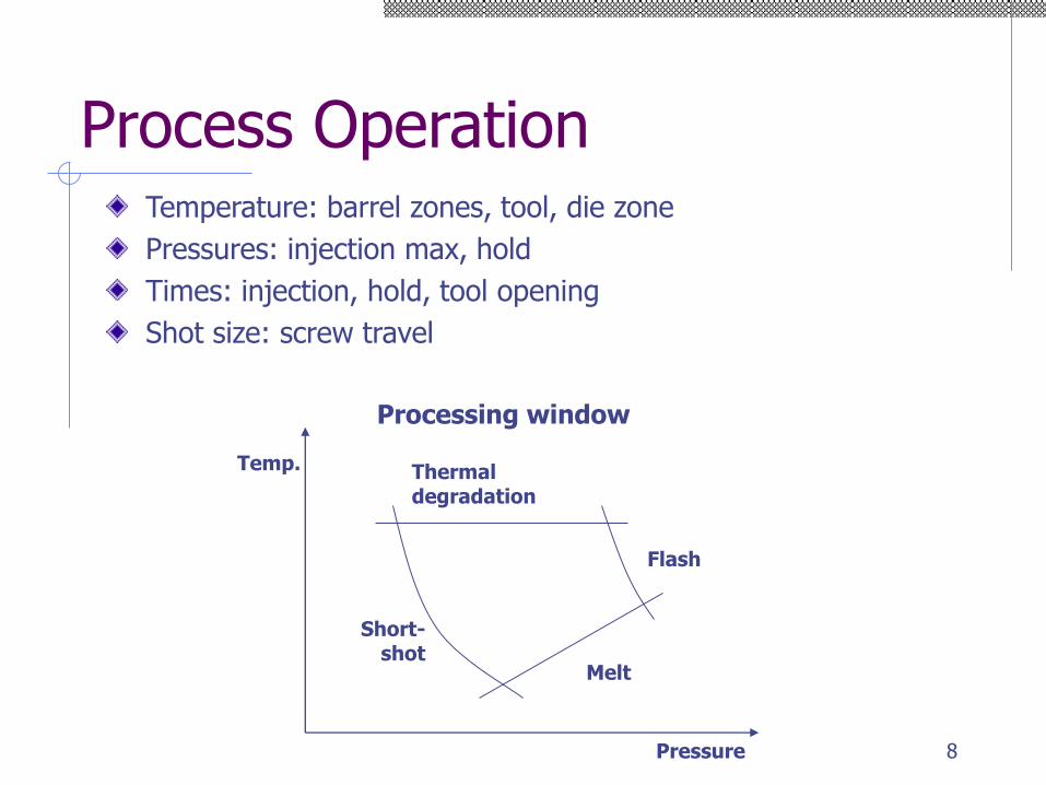
Process OperationTemperature: barrel zones, tool, die zone
Pressures: injection max, hold
Times: injection, hold, tool opening
Shot size: screw travel
Flash
Melt
Thermaldegradation
Short-shot
Temp.
Pressure
Processing window
8

Typical pressure/temperature cycle
Time(sec)
Cooling time generally dominates cycle time
Time(sec)
* Source: http://islnotes.cps.msu.edu/trp/inj/inj_time.html
**
9
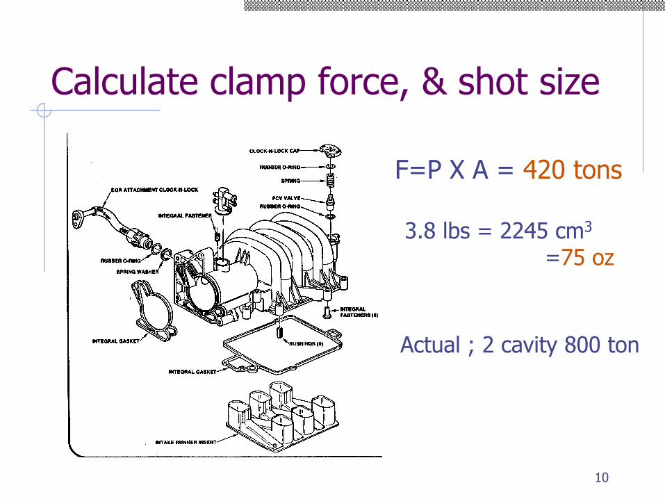
Calculate clamp force, & shot size
F=P X A = 420 tons
3.8 lbs = 2245 cm3
=75 oz
Actual ; 2 cavity 800 ton
10
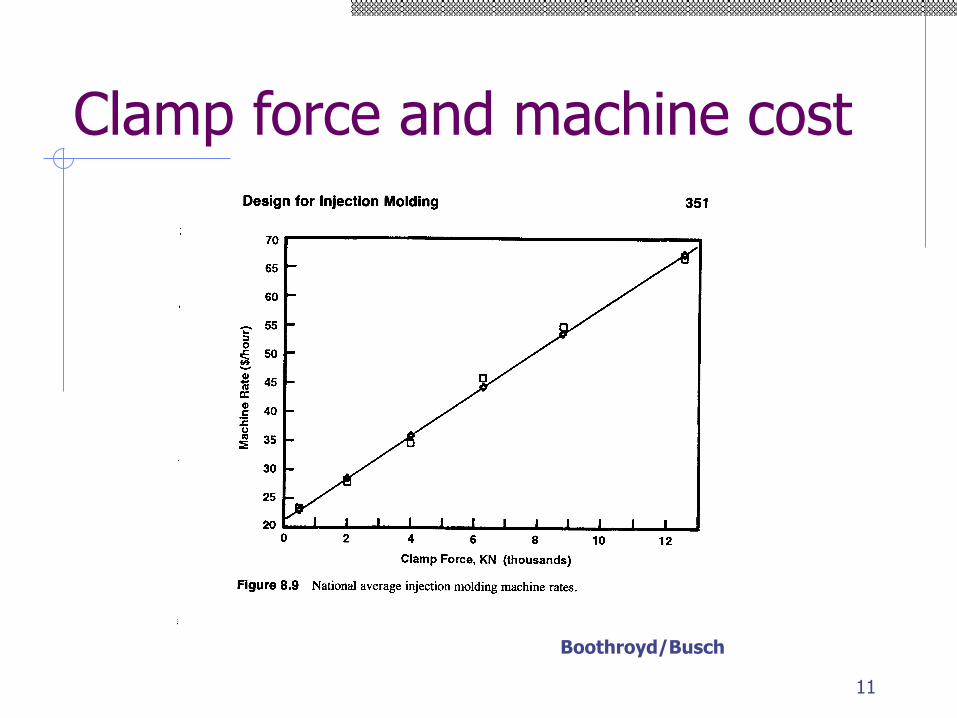
Clamp force and machine cost
Boothroyd/Busch
11
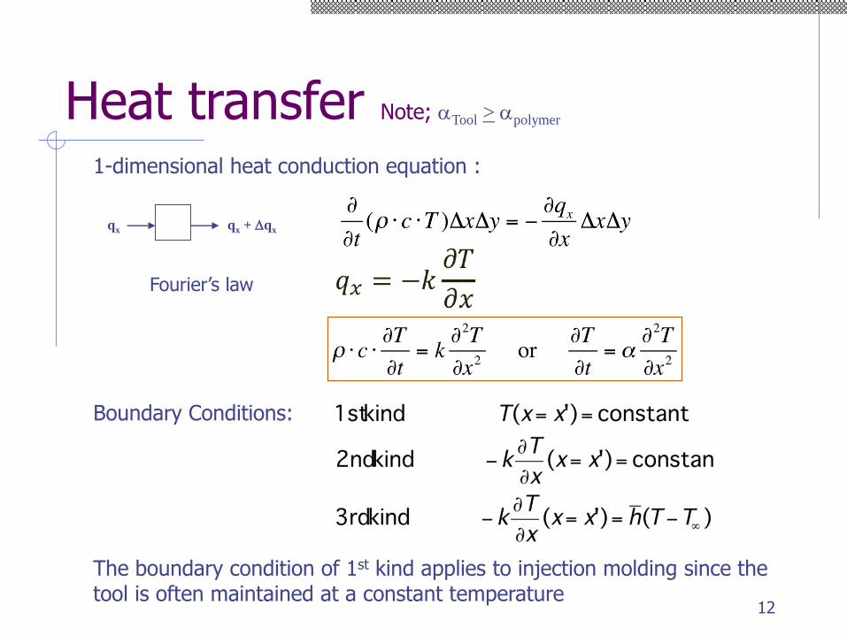
Heat transfer Note; aTool > apolymer
Boundary Conditions:
1-dimensional heat conduction equation :
The boundary condition of 1st kind applies to injection molding since the tool is often maintained at a constant temperature
qx qx + Dqx
Fourier’s law
12
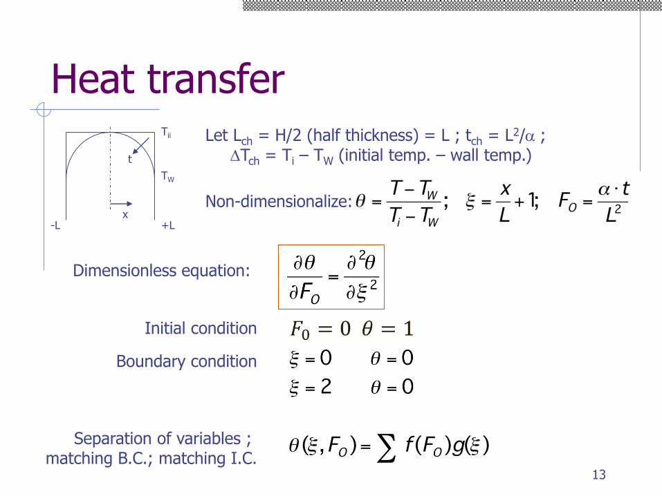
Heat transfer
TW
Tii
t
x+L-L
Let Lch = H/2 (half thickness) = L ; tch = L2/a ;DTch = Ti – TW (initial temp. – wall temp.)
Non-dimensionalize:
Dimensionless equation:
Initial condition
Boundary condition
Separation of variables ; matching B.C.; matching I.C.
13
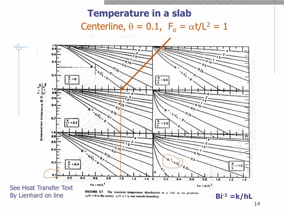
Centerline, q = 0.1, Fo = at/L2 = 1
Temperature in a slab
Bi-1 =k/hL
See Heat Transfer TextBy Lienhard on line
14
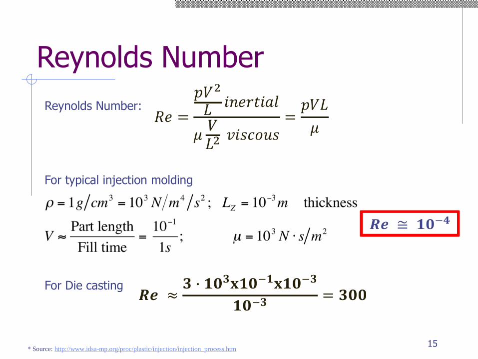
Reynolds Number
* Source: http://www.idsa-mp.org/proc/plastic/injection/injection_process.htm
Reynolds Number:
For typical injection molding
For Die casting
15
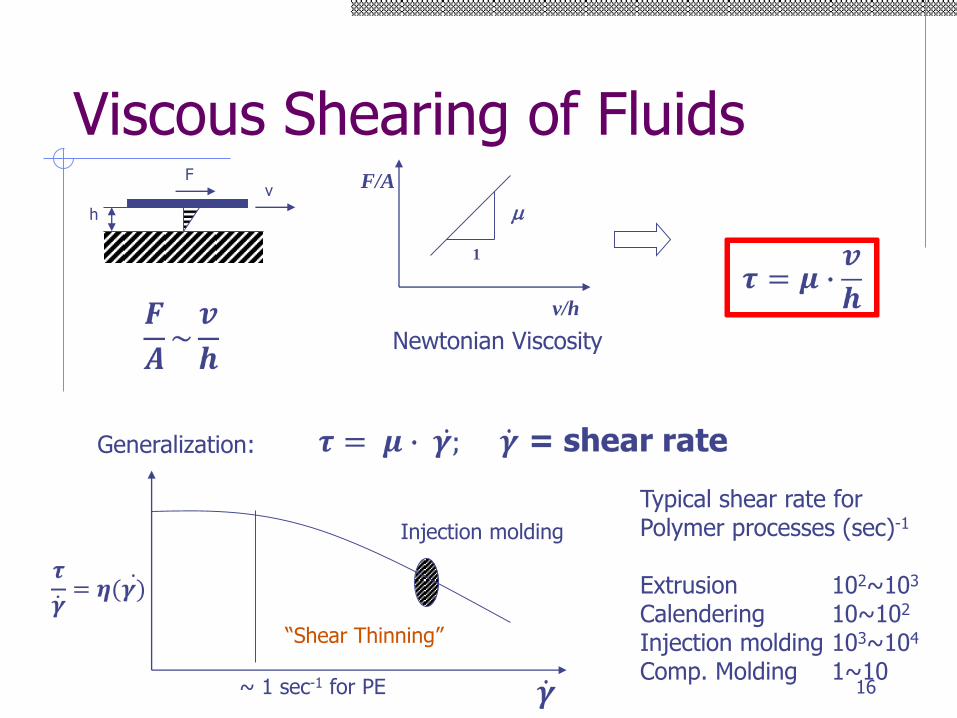
Viscous Shearing of Fluidsv
F
h
F/A
v/h
1
m
Newtonian Viscosity
Generalization:
Injection molding
Typical shear rate for Polymer processes (sec)-1
Extrusion 102~103
Calendering 10~102
Injection molding 103~104
Comp. Molding 1~10
“Shear Thinning”
~ 1 sec-1 for PE 16
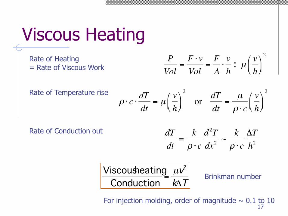
Viscous HeatingRate of Heating = Rate of Viscous Work
Rate of Temperature rise
Rate of Conduction out
Brinkman number
For injection molding, order of magnitude ~ 0.1 to 1017
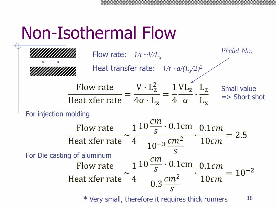
Non-Isothermal Flow
v
Flow rate: 1/t ~V/Lx
Heat transfer rate: 1/t ~a/(Lz/2)2
For injection molding
For Die casting of aluminum
* Very small, therefore it requires thick runners
Small value=> Short shot
Péclet No.
18
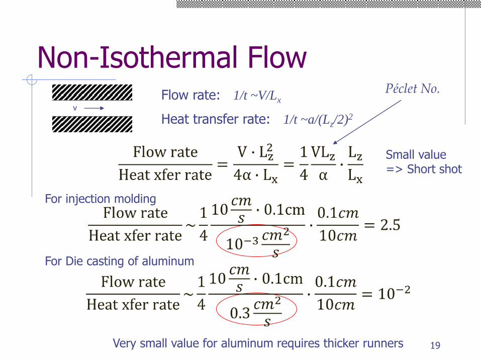
Non-Isothermal Flow
v
Flow rate: 1/t ~V/Lx
Heat transfer rate: 1/t ~a/(Lz/2)2
For injection molding
For Die casting of aluminum
Very small value for aluminum requires thicker runners
Small value=> Short shot
Péclet No.
19
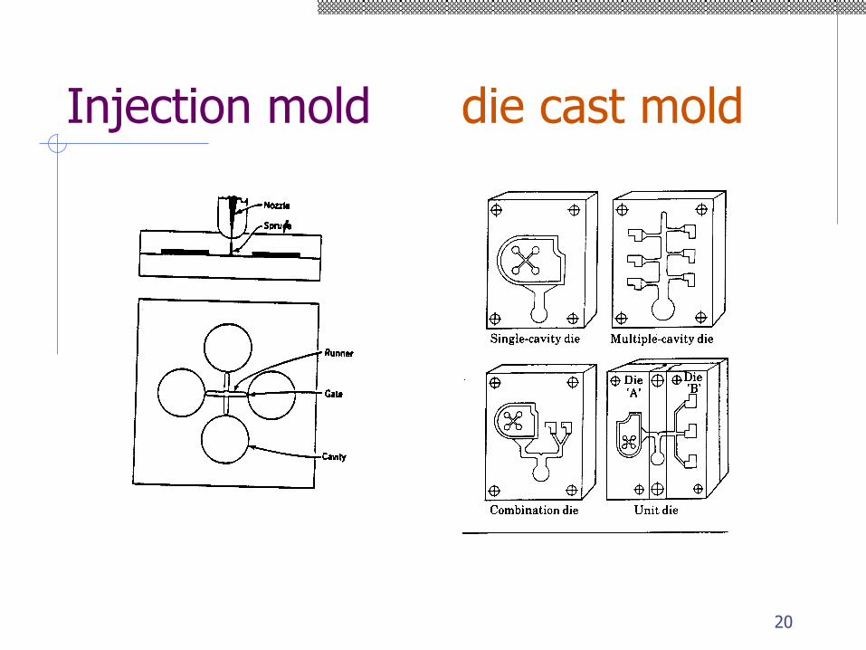
Injection mold die cast mold
20
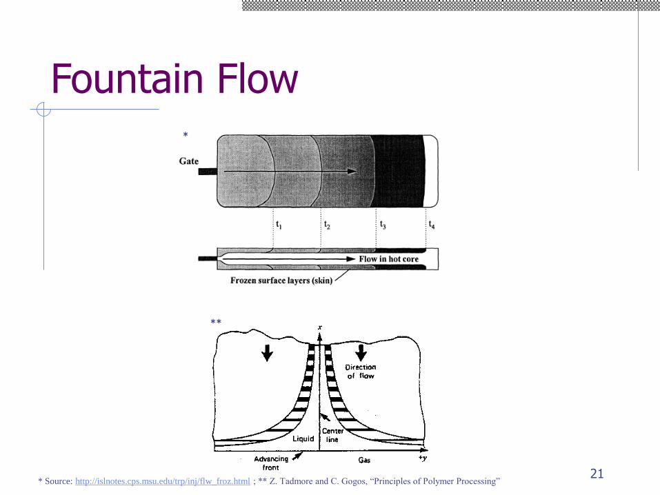
Fountain Flow
* Source: http://islnotes.cps.msu.edu/trp/inj/flw_froz.html ; ** Z. Tadmore and C. Gogos, “Principles of Polymer Processing”
*
**
21
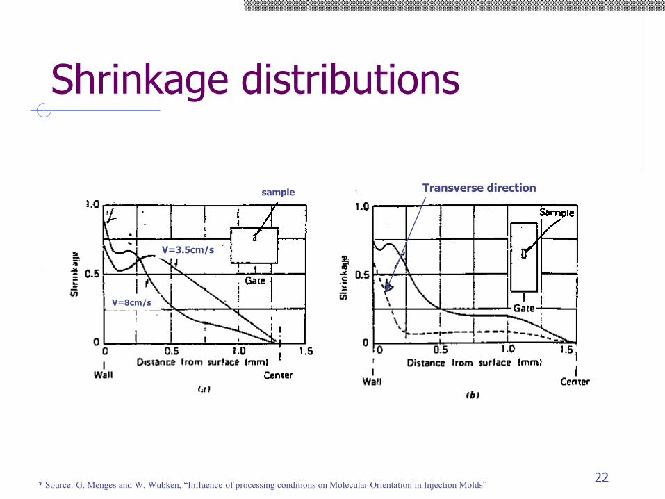
Shrinkage distributions
* Source: G. Menges and W. Wubken, “Influence of processing conditions on Molecular Orientation in Injection Molds”
V=3.5cm/s
V=8cm/s
sample Transverse direction
22
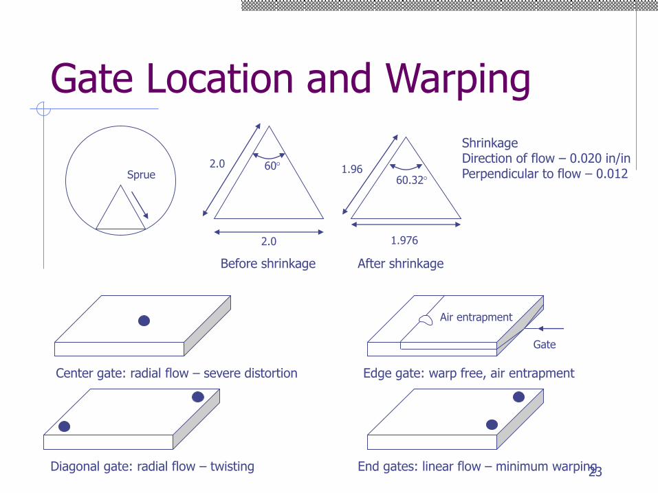
Gate Location and Warping
Center gate: radial flow – severe distortion
Diagonal gate: radial flow – twisting End gates: linear flow – minimum warping
Gate
Air entrapment
Edge gate: warp free, air entrapment
Sprue
2.0
2.0 60
Before shrinkage
60.321.96
1.976
After shrinkage
ShrinkageDirection of flow – 0.020 in/inPerpendicular to flow – 0.012
23
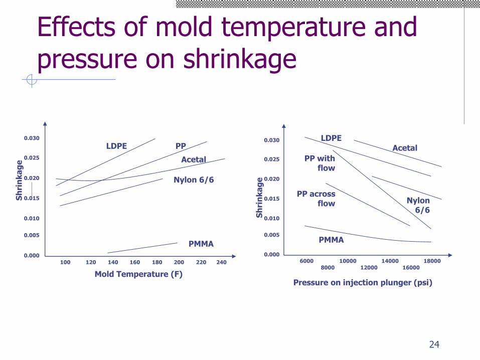
Effects of mold temperature and pressure on shrinkage
0.030
0.000
0.010
0.005
0.015
0.020
0.025
100 120 140 160 180 200 220 240
Mold Temperature (F)
LDPE PP
Nylon 6/6
PMMA
Acetal
Sh
rin
ka
ge
0.030
0.000
0.010
0.005
0.015
0.020
0.025
Sh
rin
ka
ge
6000
8000
10000
12000
14000
16000
Pressure on injection plunger (psi)
Acetal
LDPE
Nylon 6/6
PP with flow
18000
PP across flow
PMMA
24
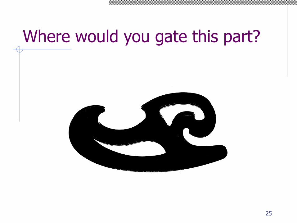
Where would you gate this part?
25
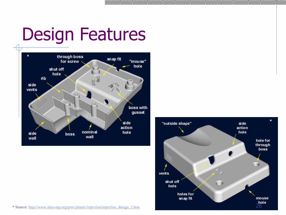
Design Features*
*
* Source: http://www.idsa-mp.org/proc/plastic/injection/injection_design_2.htm 26
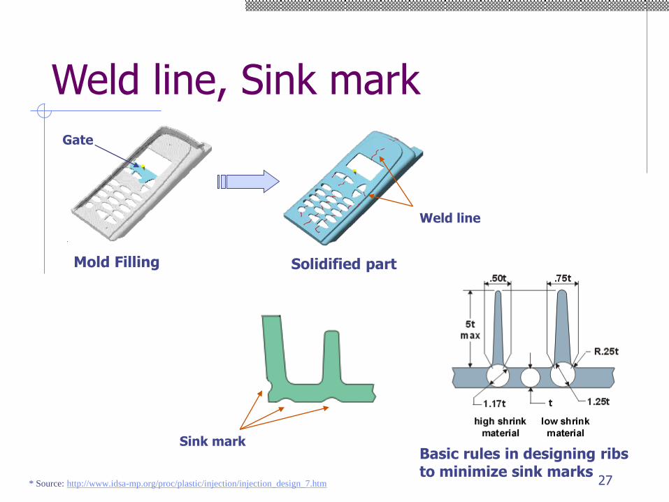
Weld line, Sink mark
* Source: http://www.idsa-mp.org/proc/plastic/injection/injection_design_7.htm
Weld line
Mold Filling
Gate
Solidified part
Sink markBasic rules in designing ribs to minimize sink marks
27
28
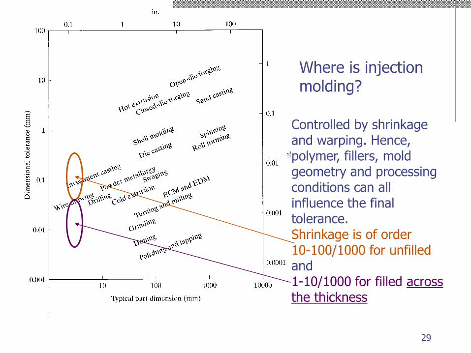
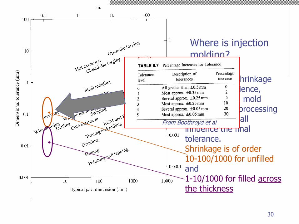
Where is injection molding?
Controlled by shrinkageand warping. Hence,polymer, fillers, moldgeometry and processingconditions can allinfluence the finaltolerance.Shrinkage is of order10-100/1000 for unfilledand1-10/1000 for filled acrossthe thickness
29
Where is injection molding?
Controlled by shrinkageand warping. Hence,polymer, fillers, moldgeometry and processingconditions can allinfluence the finaltolerance.Shrinkage is of order10-100/1000 for unfilledand1-10/1000 for filled acrossthe thickness
From Boothroyd et al
30
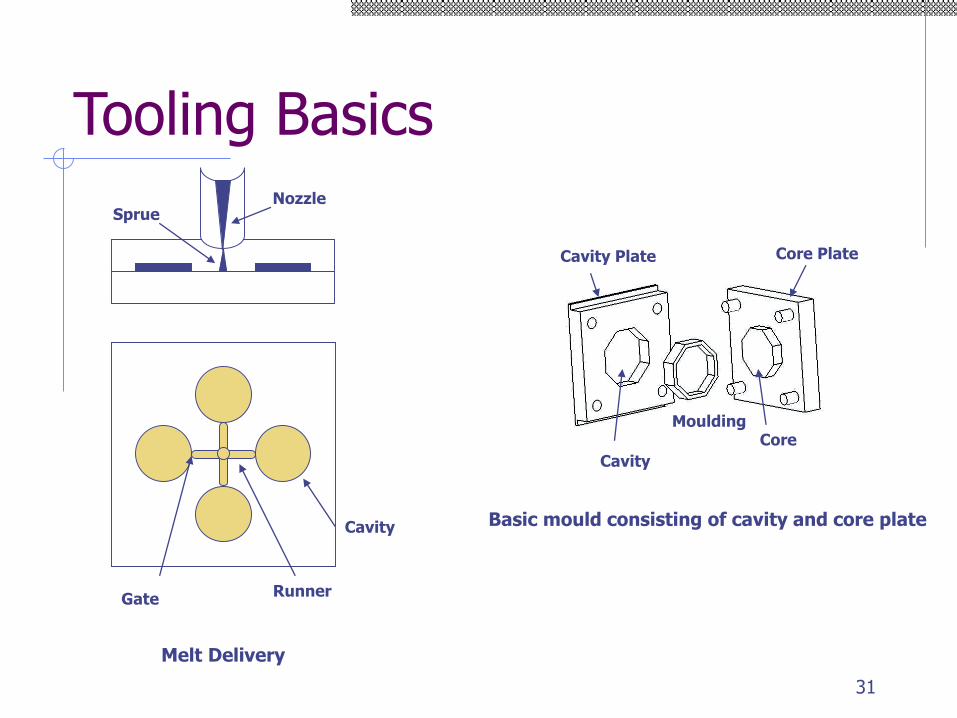
Tooling Basics
Cavity Plate
Cavity
MouldingCore
Core Plate
Basic mould consisting of cavity and core plate
Runner
Cavity
Gate
NozzleSprue
Melt Delivery
31
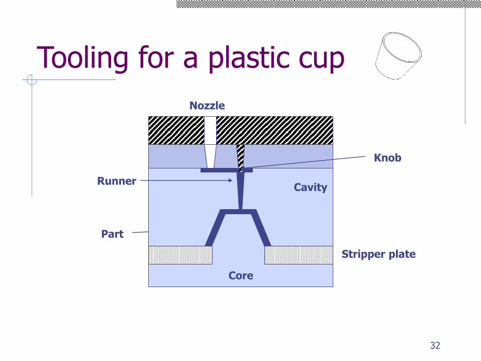
Part
Cavity
Core
Stripper plate
Tooling for a plastic cup
Runner
Knob
Nozzle
32
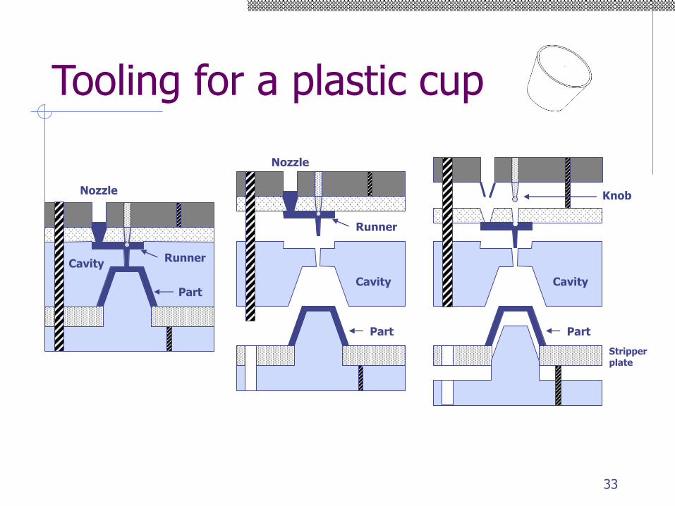
Tooling for a plastic cup
Runner
Part
Cavity
Nozzle
Part
Cavity
Knob
Stripper plate
Runner
Part
Cavity
Nozzle
33
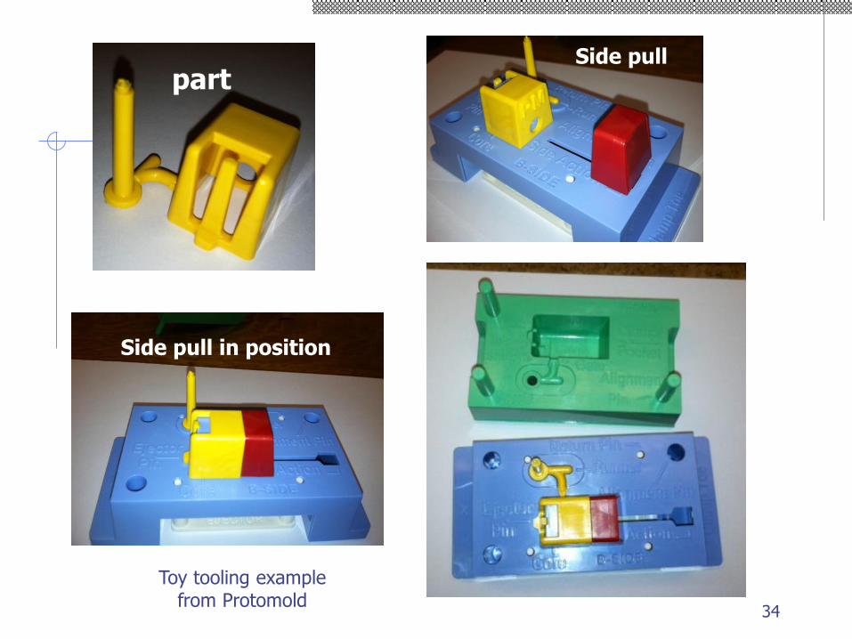
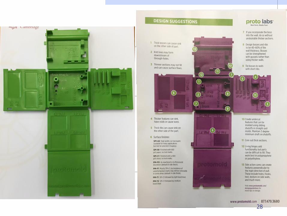
Toy tooling examplefrom Protomold
partSide pull
Side pull in position
34
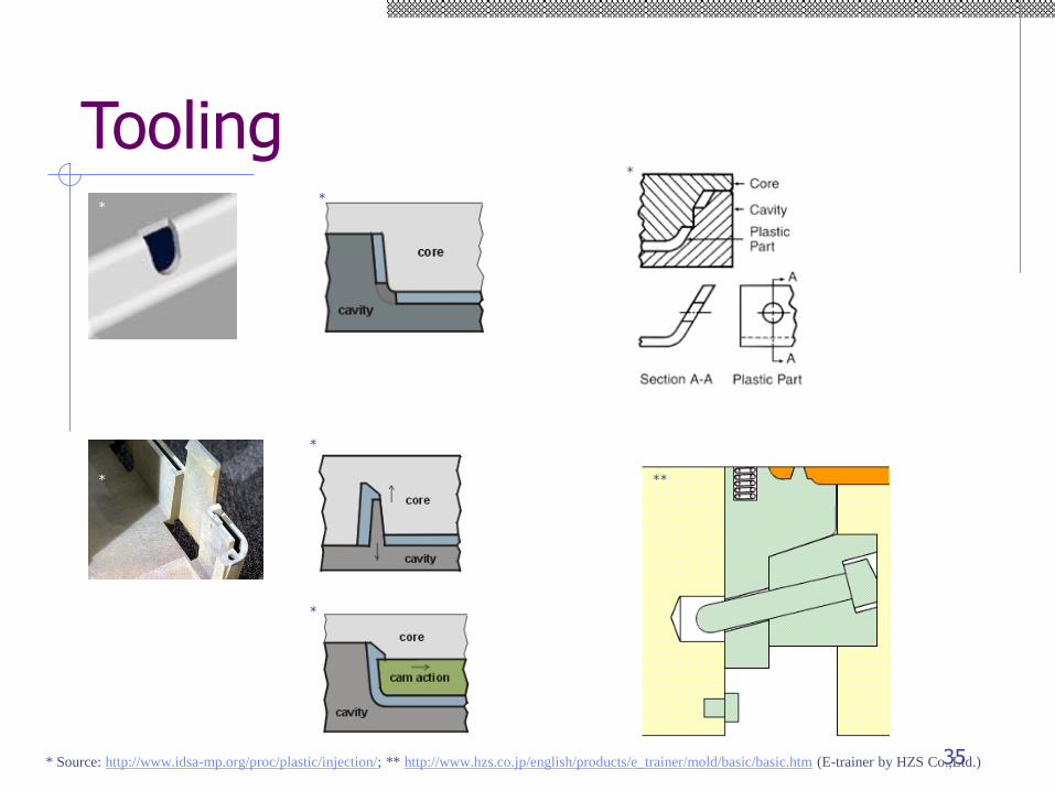
Tooling
* Source: http://www.idsa-mp.org/proc/plastic/injection/; ** http://www.hzs.co.jp/english/products/e_trainer/mold/basic/basic.htm (E-trainer by HZS Co.,Ltd.)
**
*
*
*
* **
35
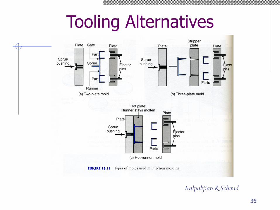
Tooling Alternatives
Kalpakjian & Schmid
36
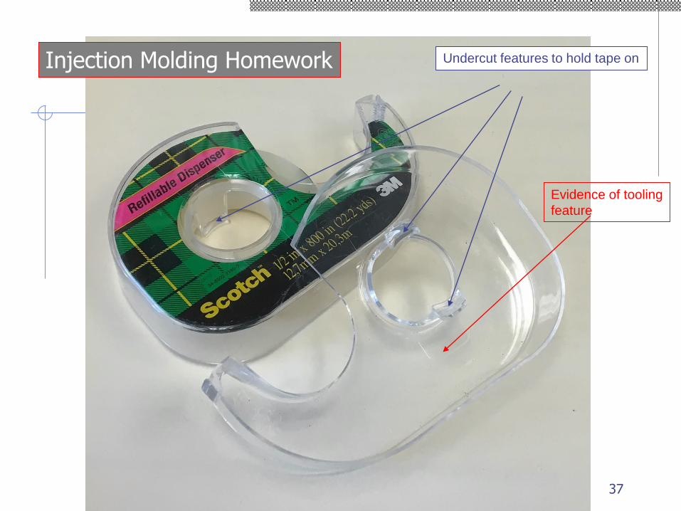
Undercut features to hold tape on
Evidence of tooling
feature
Injection Molding Homework
37
Part design rules
Simple shapes to reduce tooling cost◼ No undercuts, etc.
Draft angle to remove part◼ In some cases, small angles (1/4) will do
◼ Problem for gears
Even wall thickness
Minimum wall thickness ~ 0.025 in
Avoid sharp corners
Hide weld lines◼ Holes may be molded 2/3 of the way through the
wall only, with final drilling to eliminate weld lines38
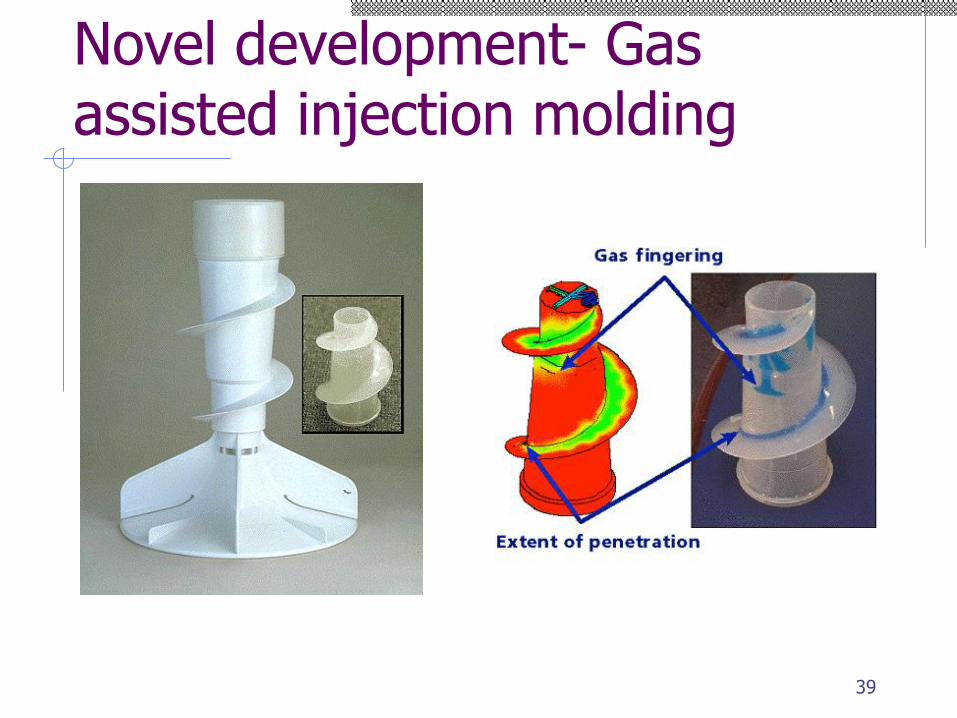
Novel development- Gas assisted injection molding
39
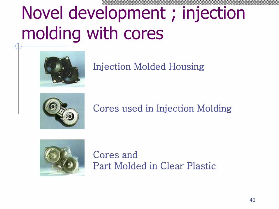
Novel development ; injection molding with cores
Cores and Part Molded in Clear Plastic
Cores used in Injection Molding
Injection Molded Housing
40
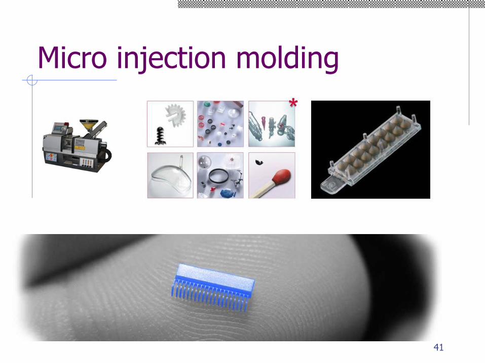
Micro injection molding
41
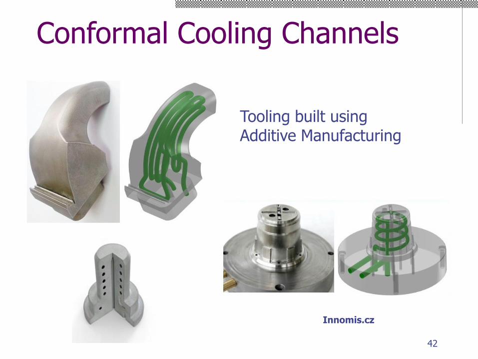
Conformal Cooling Channels
Innomis.cz
Tooling built usingAdditive Manufacturing
42
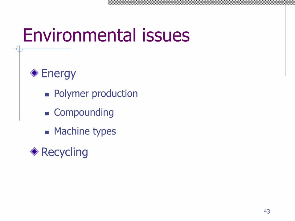
Environmental issues
Energy
◼ Polymer production
◼ Compounding
◼ Machine types
Recycling
43
44
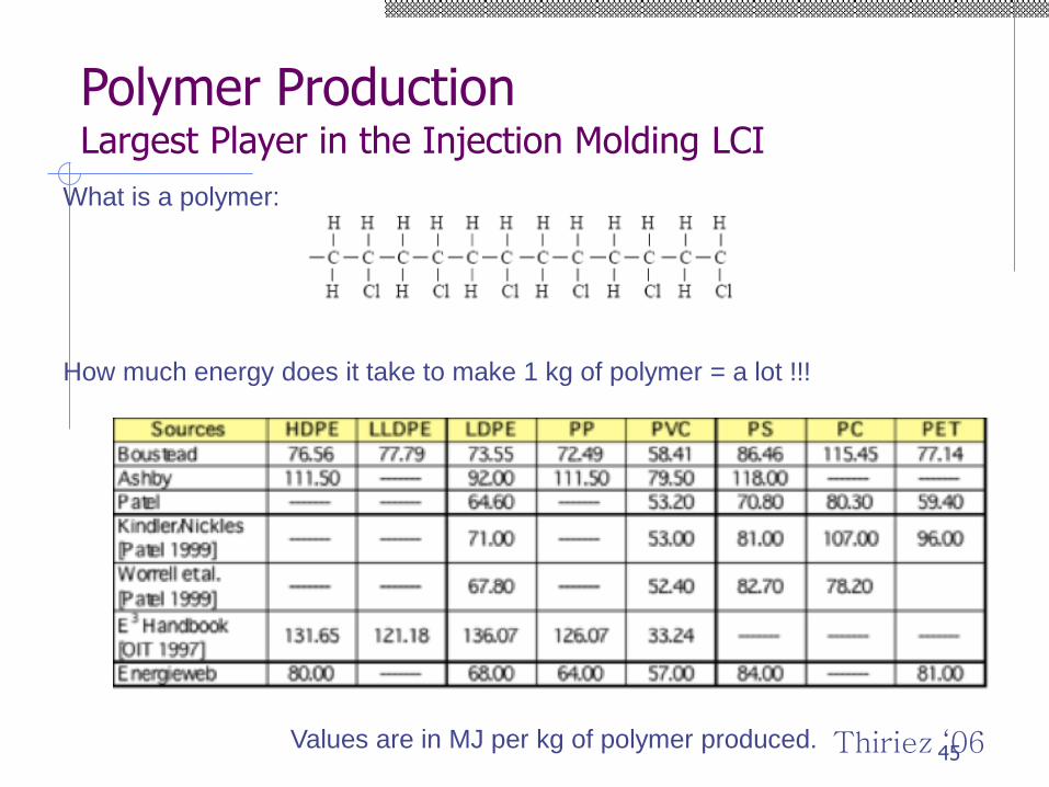
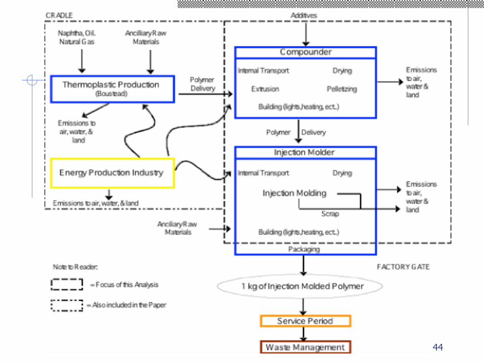
Polymer ProductionLargest Player in the Injection Molding LCI
What is a polymer:
How much energy does it take to make 1 kg of polymer = a lot !!!
Values are in MJ per kg of polymer produced. Thiriez ‘0645
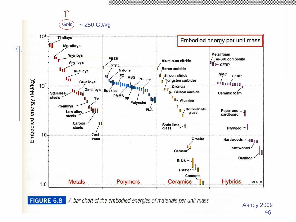
Gold ~ 250 GJ/kg
Ashby 2009
46
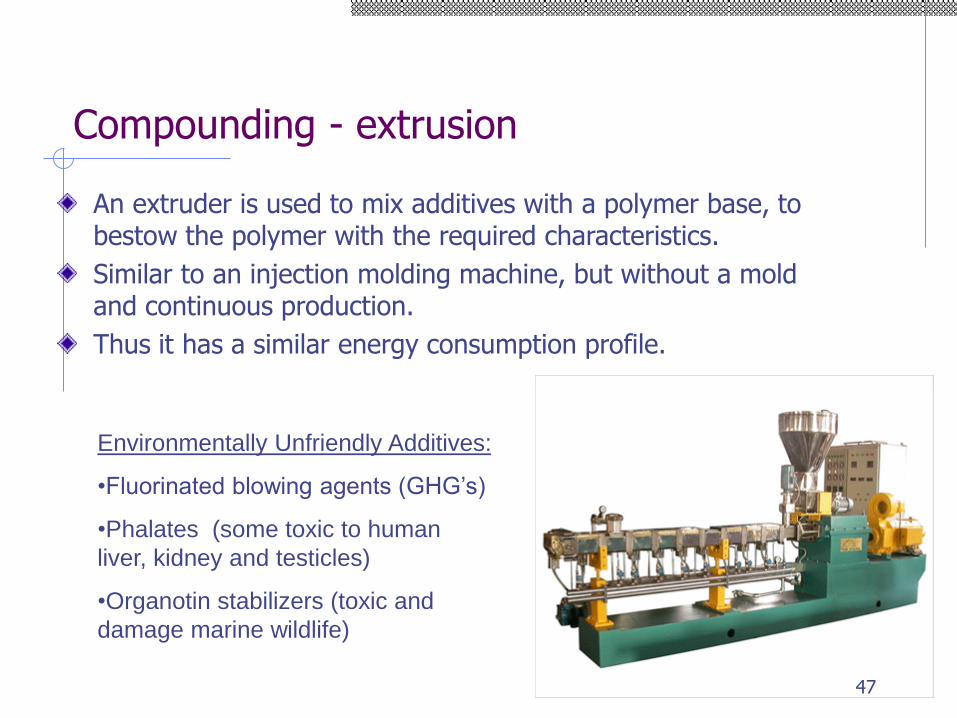
Compounding - extrusion
An extruder is used to mix additives with a polymer base, to bestow the polymer with the required characteristics.
Similar to an injection molding machine, but without a mold and continuous production.
Thus it has a similar energy consumption profile.
Environmentally Unfriendly Additives:
•Fluorinated blowing agents (GHG’s)
•Phalates (some toxic to human
liver, kidney and testicles)
•Organotin stabilizers (toxic and
damage marine wildlife)
47
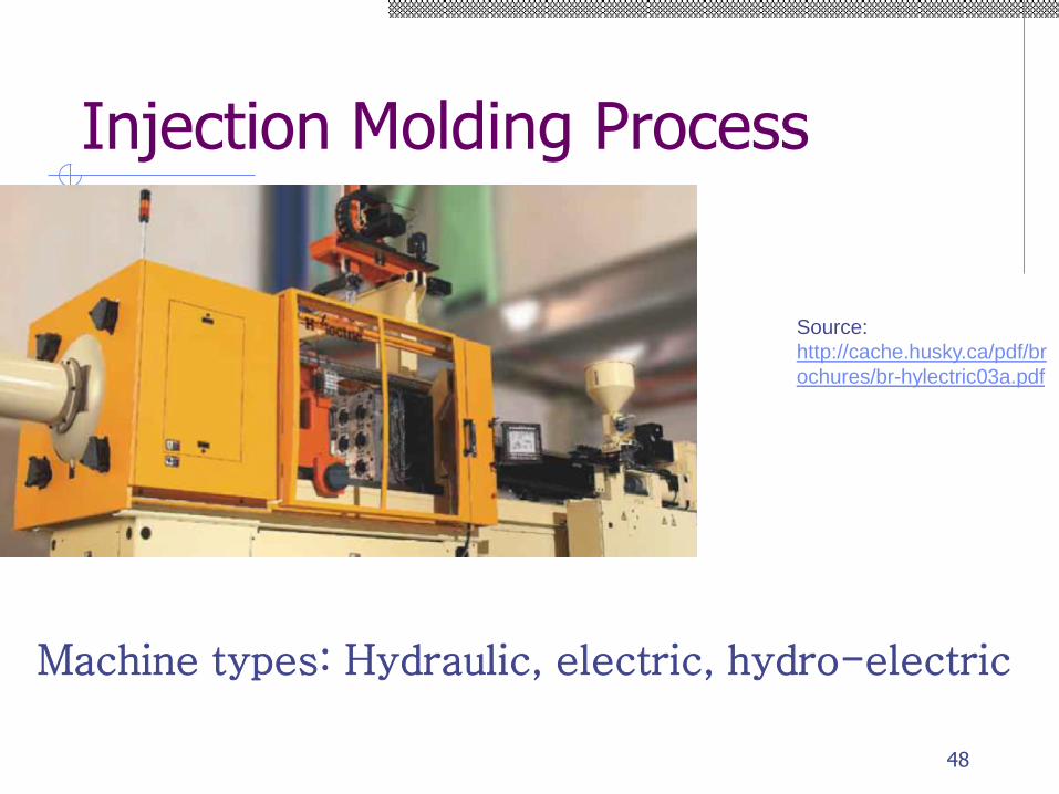
Injection Molding Process
Source:
http://cache.husky.ca/pdf/br
ochures/br-hylectric03a.pdf
Machine types: Hydraulic, electric, hydro-electric
48
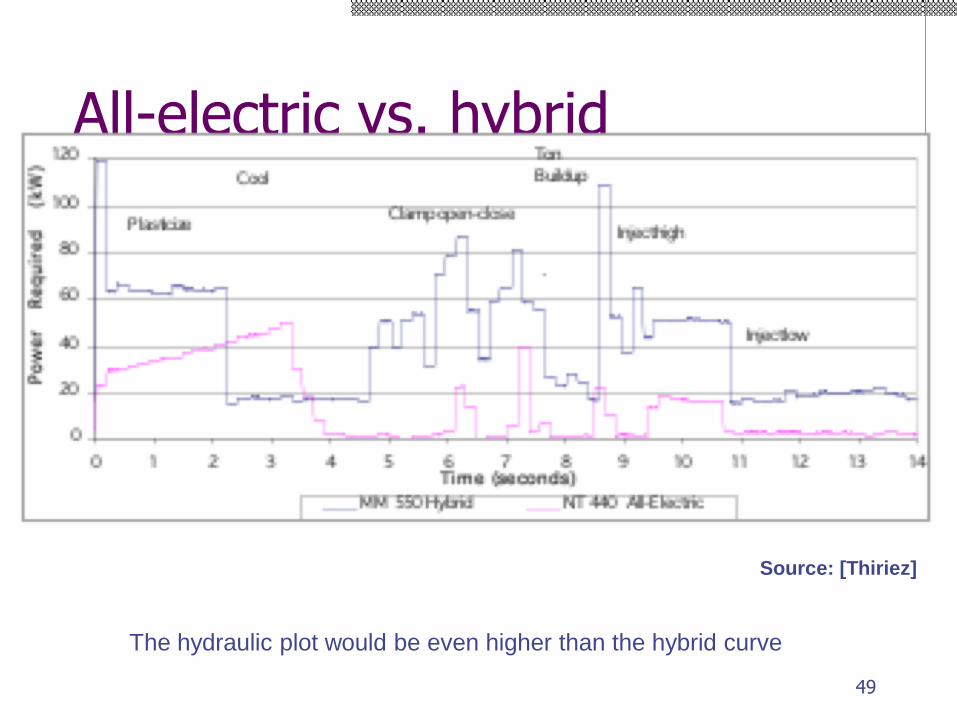
All-electric vs. hybrid
The hydraulic plot would be even higher than the hybrid curve
Source: [Thiriez]
49
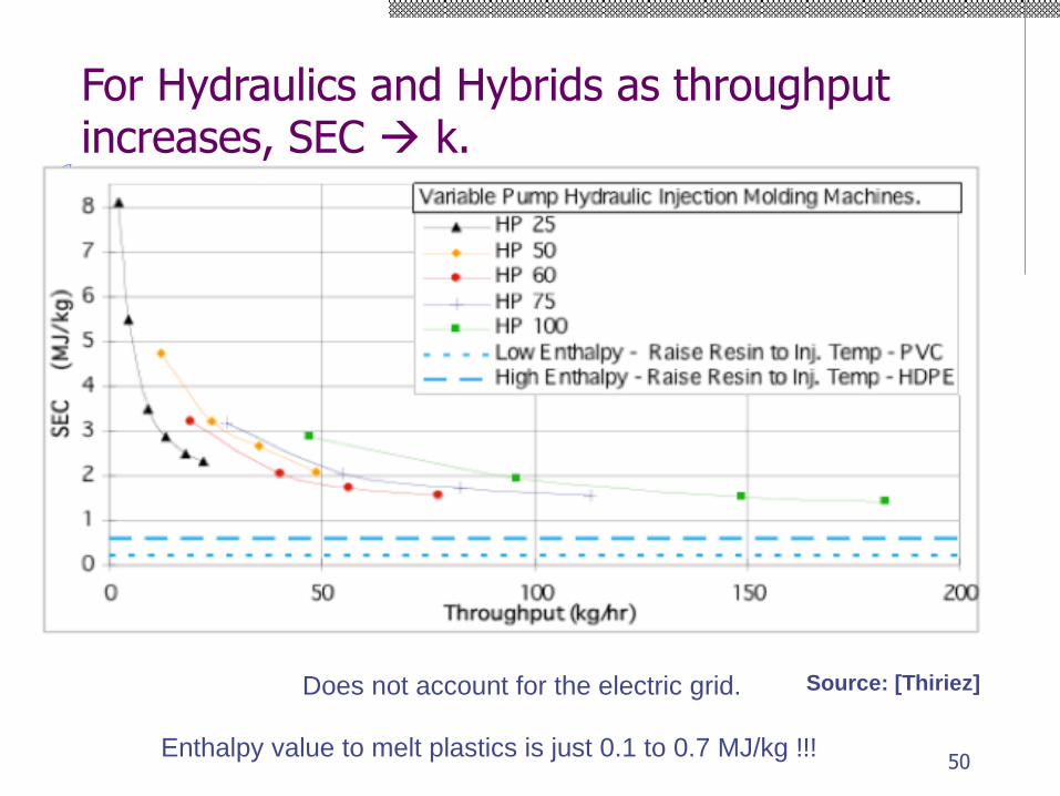
For Hydraulics and Hybrids as throughput increases, SEC → k.
Enthalpy value to melt plastics is just 0.1 to 0.7 MJ/kg !!!
Does not account for the electric grid. Source: [Thiriez]
50
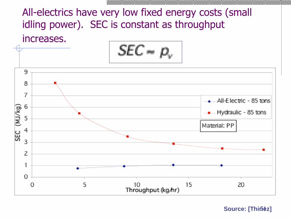
All-electrics have very low fixed energy costs (small idling power). SEC is constant as throughput
increases.
Source: [Thiriez]51
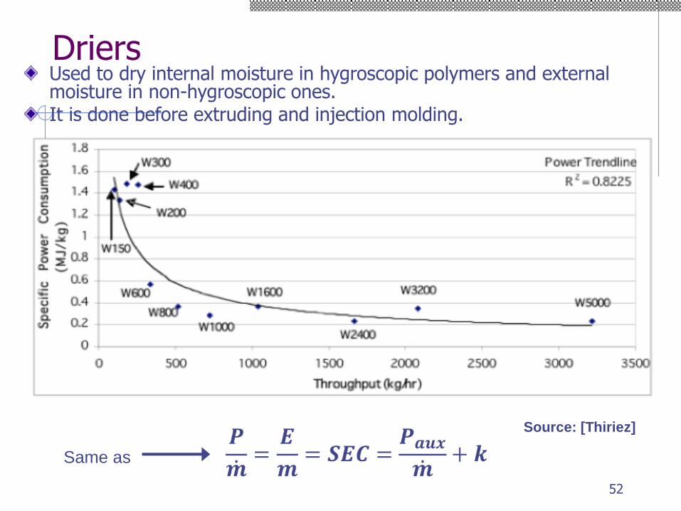
DriersUsed to dry internal moisture in hygroscopic polymers and external moisture in non-hygroscopic ones. It is done before extruding and injection molding.
Source: [Thiriez]
Same as
52
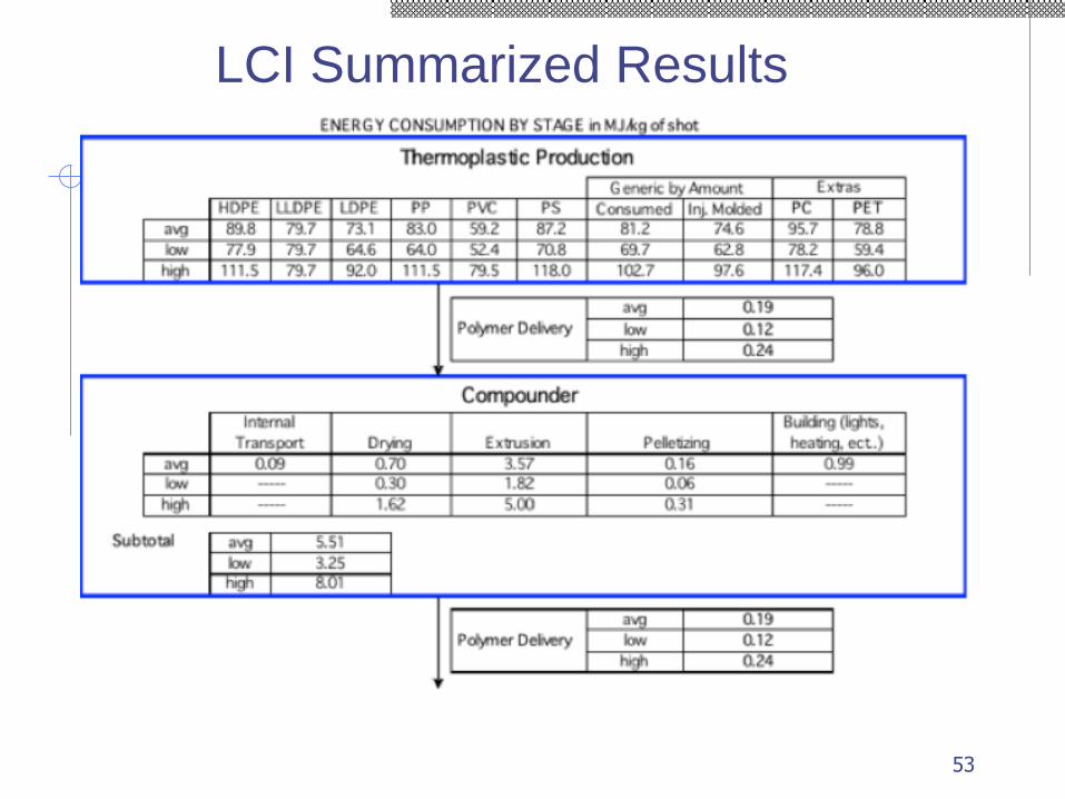
LCI Summarized Results
53
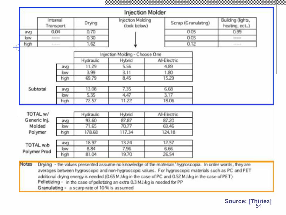
Source: [Thiriez]54
55
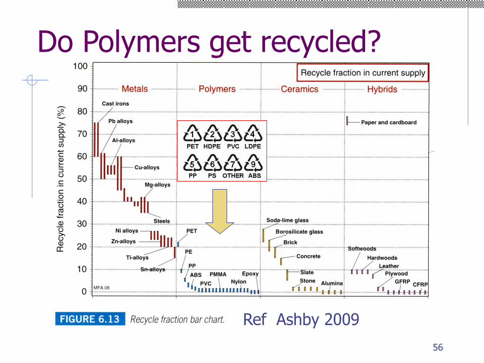
Do Polymers get recycled?
Ref Ashby 2009
56
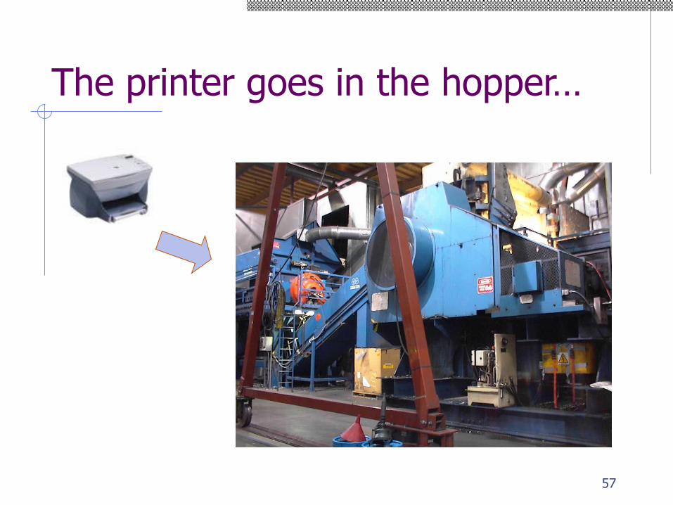
The printer goes in the hopper…
57
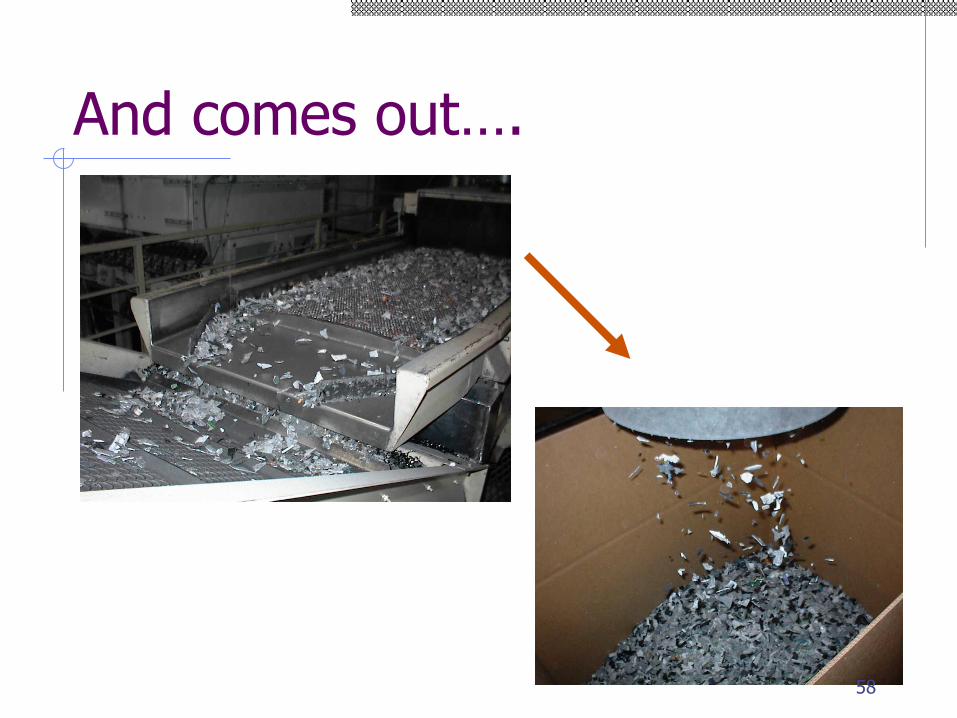
And comes out….
58

Readings (first 3) & Refs
Tadmore and Gogos
◼ Molding and Casting pp 584 -610
Boothroyd Dewhurst
◼ Design for Injection Molding pp 319 - 359
Kalpakjian Ch 7 & 19
Thiriez et al, "An Environmental Analysis of Injection
Molding“
"Injection Molding Case Study“ (Gas Assist)
59