Infusion Pump Operator’s Manual - Eickemeyer - Welkom Infusovet... · Infusion Pump ....
72
Infusion Pump Operator’s Manual
Transcript of Infusion Pump Operator’s Manual - Eickemeyer - Welkom Infusovet... · Infusion Pump ....
Infusion Pump
Operator’s Manual


The issue date for this Operator’s Manual is April 2013. Version:1.0

Preface
Purpose of the Manual This Operator’s Manual describes the product’s application, function and operation in detail. Please read this Operator’s Manual carefully and understand the content before use, in order to ensure the proper usage and guarantee the safety of the patient and the user. This Operator’s Manual describes the product as per the most complete configuration. Some content of this manual may not be applicable for the product you are handling. Please contact us if you have any questions. Please store this Operator’s Manual with the infusion pump in order to consult it at your convenience.
Intended Audience This Operator’s Manual is only applicable to use by suitably qualified clinicians.
Illustrations All illustrations in this Operator’s Manual are used for reference only. Settings or data shown may not be entirely consistent with the actual information displayed on the product. Conventions
Italic text is used in this manual to quote referenced chapters or sections.
The terms “Danger”, ”Warning”, and “Caution” are used throughout this manual to point out hazards and to designate a degree or level of severity.
Contents 1 Safety .................................................................................................................... 1-1 1.1 Safety Information .............................................................................................. 1-1
1.1.1 DANGER ................................................................................................ 1-2 1.1.2 WARNING .............................................................................................. 1-2 1.1.3 CAUTION ............................................................................................... 1-3 1.1.4 NOTE ...................................................................................................... 1-5
1.2 Equipment Symbols............................................................................................ 1-6
2 Overview ............................................................................................................... 2-1 2.1 Product Introduction ........................................................................................... 2-1
2.1.1 Scope of Use .......................................................................................... 2-1 2.1.2 Contraindications .................................................................................... 2-1 2.1.3 Product Structure, Composition and Performance ................................ 2-1
2.2 Product Exterior .................................................................................................. 2-3 2.2.1 Front View .............................................................................................. 2-3 2.2.2 Rear View ............................................................................................... 2-5
2.3 Screen Display ................................................................................................... 2-6 2.4 Battery ................................................................................................................ 2-6
2.4.1 Overview ................................................................................................. 2-6 2.4.2 Battery Guidelines .................................................................................. 2-7 2.4.3 Battery Maintenance .............................................................................. 2-8
2.4.3.1 Battery Optimization ....................................................................... 2-8 2.4.3.2 Checking the Battery ...................................................................... 2-8
2.4.4 Battery Recycling ................................................................................... 2-9
3 Installation and Maintenance ............................................................................. 3-1 3.1 Installation ........................................................................................................... 3-1
3.1.1 Out of Box Audit (OOBA) ....................................................................... 3-1 3.1.2 Environmental Requirements ................................................................. 3-2 3.1.3 Power Supply Requirements .................................................................. 3-2 3.1.4 Fixing the Infusion Pump ........................................................................ 3-3 3.1.5 Installing the Power Cord ....................................................................... 3-4 3.1.6 Installing the Drop Sensor (optional) ...................................................... 3-4
3.2 Maintenance ....................................................................................................... 3-6 3.2.1 Inspection ............................................................................................... 3-6 3.2.2 Cleaning and Disinfection ...................................................................... 3-7 3.2.3 Periodic Maintenance ............................................................................. 3-8 3.2.4 Pollution-Free Disposal and Recycling .................................................. 3-9
4 Operation Guide .................................................................................................. 4-1
4.1 Operation Flow Chart ......................................................................................... 4-1 4.2 Operating Steps .................................................................................................. 4-2
4.2.1 Turning on the Infusion Pump ................................................................ 4-2 4.2.2 Installing the Infusion Tube .................................................................... 4-3 4.2.3 Setting the Infusion Parameters ............................................................. 4-4 4.2.4 Clearing the Accumulated Volume ......................................................... 4-5 4.2.5 Starting the Infusion ................................................................................ 4-5 4.2.6 Infusion Finished .................................................................................... 4-5 4.2.7 Turning off the Infusion Pump ................................................................ 4-5
5 Function and Interface ........................................................................................ 5-1 5.1 Main Interface and Parameters .......................................................................... 5-1 5.2 Bolus Function .................................................................................................... 5-2 5.3 Drop Rate Function and Setting (Optional) ........................................................ 5-2
5.3.1 Starting the Drop Rate Function ............................................................. 5-3 5.3.2 Setting the Drop Rate for the Infusion Tube .......................................... 5-3 5.3.3 Viewing the Drop Rate Interface ............................................................ 5-4
5.4 Using a Different Brand of Tube ......................................................................... 5-5 5.4.1 Selecting the Infusion Tube .................................................................... 5-5 5.4.2 Accuracy Calibration............................................................................... 5-7 5.4.3 Pressure Adjustment .............................................................................. 5-7
5.5 Setting the Occlusion Level ................................................................................ 5-9 5.6 Setting the Air Bubble Filter Level ...................................................................... 5-9 5.7 Automatic Pressure Release Function (Anti-Bolus) ......................................... 5-10 5.8 KVO Function ................................................................................................... 5-10
6 Alarms ................................................................................................................... 6-1 6.1 Overview ............................................................................................................. 6-1 6.2 Alarm Levels and Methods ................................................................................. 6-1 6.3 Pausing the Alarm Tone ..................................................................................... 6-2 6.4 Alarm Countermeasures ..................................................................................... 6-2
A Product Specifications ....................................................................................... A-1 A.1 Safety Specifications .......................................................................................... A-1 A.2 Environmental Specifications ............................................................................. A-1 A.3 Power Specifications .......................................................................................... A-2 A.4 Hardware Specifications .................................................................................... A-2 A.5 Basic Infusion Pump Parameters ...................................................................... A-3 A.6 Occlusion Alarm Pressures, Maximum Delays for Alarm Times and Maximum Permissible Dose Volumes ....................................................................................... A-4 A.7 Infusion Accuracy Table ..................................................................................... A-5
B EMC ...................................................................................................................... B-1

C Alarm Information ............................................................................................... C-1 C.1 Alarm Information ............................................................................................... C-1 C.2 Prompt Messages .............................................................................................. C-6
D Symbols and Terms ............................................................................................ D-1 D.1 List of Units ........................................................................................................ D-1 D.2 List of Terms ....................................................................................................... D-2

FOR YOUR NOTES
1-1
1 Safety
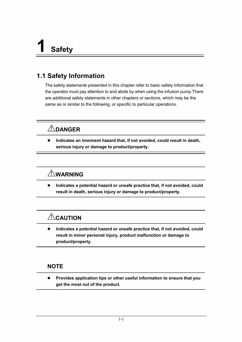
1.1 Safety Information The safety statements presented in this chapter refer to basic safety information that the operator must pay attention to and abide by when using the infusion pump.There are additional safety statements in other chapters or sections, which may be the same as or similar to the following, or specific to particular operations.
DANGER
Indicates an imminent hazard that, if not avoided, could result in death, serious injury or damage to product/property.
WARNING
Indicates a potential hazard or unsafe practice that, if not avoided, could result in death, serious injury or damage to product/property.
CAUTION
Indicates a potential hazard or unsafe practice that, if not avoided, could result in minor personal injury, product malfunction or damage to product/property.
NOTE
Provides application tips or other useful information to ensure that you get the most out of the product.
1-2
1.1.1 DANGER
DANGER
The infusion tube must be installed straight and level in the bottom of the groove on the infusion pump.
1.1.2 WARNING
WARNING
This infusion pump is intended to be used for clinical intravenous infusion. It is not intended to be used for enteral and endogastric nutrition infusion. It can only be used by professional clinicians, medical electrical experts, or suitably trained nurses on specific occasions.
The infusion pump and its accessories must be inspected before use to guarantee their normal and safe operation.
Avoid using this infusion pump in a flammable or explosive atmosphere in case of fire outbreak or explosion.
Infusion alarms must be set based on the actual situation of the patients.Do not rely too heavily on the audible alarm system during infusion supervision. Pay close attention to the actual clinical situation of the patient.
Keep monitoring the remaining liquid volume in the infusion bags (or infusion bottles) and check that there are no air bubbles in the infusion tubes during the infusion. Do not rely solely on the alarm function of the infusion pump.
The pressure detector may not work normally in high-pressure environments, especially in hyperbaric oxygen therapy.
Make sure the blood vessel is well protected before infusion.
In the infusion tube, occlusion caused by tube knots and filter coagulation or intubations may cause the pressure inside the infusion tube to rise.If this occurs, the effort to eliminate the occlusion may cause an excessive dose of liquid to be infused into the patient’s body.Appropriate measures should be taken to prevent this situation.For example,clamp the infusion tube before eliminating the
1-3
occlusion.
This infusion pump should be used 120 cm above or below the patient’s heart.
Avoid using the infusion pump when an alarm is sounding.
When another set of infusion systems or accessories is connected to the infusion tube used in this infusion pump, the operation of this pump may not meet its specifications.
Only standard components, connectors and disposable products can be used with this pump.Subsidiary items must not be attached to the pump and its accessories. Modification of the pump is prohibited and may lead to unexpected consequences.
The pump's accuracy will not be maintained when it is used with a non-standard infusion tube or the parameters of the infusion tube are not set accurately. The maximum deviation may reach 40% or above.
Disposable accessories must be disposed of after use in accordance with the relevant hospital regulations.
This infusion pump belongs to Class II (type of electric shock protection); the supplied Type I power cord PE earth terminal should not be used as ground protection and functional earthing.
Do not open the casing of the infusion pump, as you may suffer an electric shock.The infusion pump must be maintained or updated by maintenance staff trained and authorized by our company.
The packaging materials must be disposed of in compliance with local laws and regulations or the hospital policy on waste management.They must be kept out of the reach of children.
The double thickness of the infusion tube should be between 0.8 mm–1.2 mm. The outer diameter should be between 3.5 mm–4.5 mm.
Otherwise, its accuracy cannot be guaranteed, and may cause serious injury to patients.
1.1.3 CAUTION
CAUTION
Please use the accessories specified in this Operator’s Manual to guarantee the patient’s safety.
Cables must be connected carefully to reduce the possibility of the
1-4
patient choking or getting caught in them.
Disposable accessories can only be used once. Repeated use may lead to deterioration in performance or cross-infection.
After installation of the infusion tube and before infusion, check for leakages. If any are found, they should be rectified as soon as possible.
Adjust the fixing site of the infusion tube every 4 hours after infusion begins, in order to guarantee its accuracy.Replace the infusion tube after the infusion has been running for 24 hours.
When this infusion pump and its accessories exceed their service life, they must be disposed of in accordance with local statutes or hospital regulations.If you have any queries, please contact your distributor or the manufacturer.
Electromagnetic fields may influence the performance of the infusion pump. Therefore, equipment or devices used in the vicinity of the infusion pump must meet the EMC standard.Mobile phones, X ray and MRI equipment are all potential interference sources because of their high-intensity electromagnetic radiation.
Avoid direct sunshine, high temperatures and humidity.
Avoid exposing this infusion pump to high-pressure sterilization or chemical materials.
Check the built-in battery before use to make sure it has sufficient power.Recharge the battery if necessary.
Before the infusion pump is connected to the power supply, make sure the voltage and frequency of the power supply comply with the label on the pump or the specific requirements outlined in this Operator’s Manual.
Please install and carry the infusion pump appropriately to protect the pump from being dropped, knocked, violently shaken, or suffering other damage caused by forces external to the machine.
Use a piece of soft cloth dampened with warm water to wipe the surface of the infusion pump if any liquid is spilled on it.
If the surface tension, specific gravity and viscosity of the infusion solution are different from saline (for example, a kind of solution mixed with surfactant), the infusion accuracy may be different from the accuracy listed in the specifications table.
When the infusion rate is high (≥ 1000 ml/h), high-quality silicone tubes with 0.9 mm transfusion needles must be used with the pump in order to maintain infusion accuracy.
If the infusion pump fails to work as specified in the Operator’s Manual and the cause is uncertain, stop the infusion and report the situation
1-5
(including infusion accessories used with the pump, infusion volume, infusion rate, serial number, liquid type, etc.) to your distributor or the manufacturer.
The drop sensor is not applicable to light-proof medicine infusions. Adopting light-proof IV sets on the pumps might cause the drop sensor to fail and result in serious injury to patients.
1.1.4 NOTE
NOTE
Keep this Operator’s Manual near to the infusion pump for ease of future reference.
Install the infusion pump where convenient for its supervision, operation and maintenance.
This Operator’s Manual describes all the settings and functions of the infusion pump in its most complete functional configuration. The infusion pump you are handling may not have some of the settings or functions described herein.
Do not insert devices that are not specified by our company into the data interface.
1-6
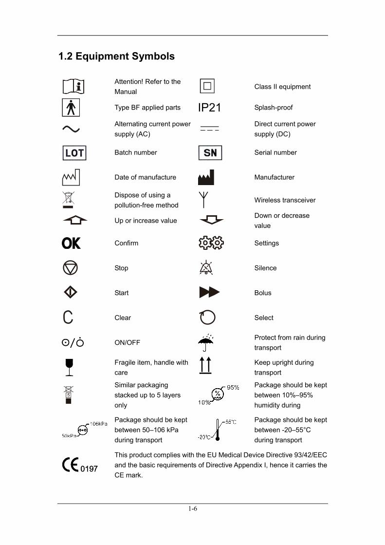
1.2 Equipment Symbols
Attention! Refer to the Manual
Class II equipment
Type BF applied parts IP21 Splash-proof
Alternating current power supply (AC)
Direct current power supply (DC)
Batch number
Serial number
Date of manufacture
Manufacturer
Dispose of using a pollution-free method
Wireless transceiver
Up or increase value Down or decrease value
Confirm
Settings
Stop
Silence
Start
Bolus
Clear
Select
ON/OFF
Protect from rain during transport
Fragile item, handle with care
Keep upright during transport
Similar packaging stacked up to 5 layers only
Package should be kept between 10%–95% humidity during
Package should be kept between 50–106 kPa during transport
Package should be kept between -20–55°C during transport
This product complies with the EU Medical Device Directive 93/42/EEC and the basic requirements of Directive Appendix I, hence it carries the CE mark.
2-1
2 Overview
2.1 Product Introduction
2.1.1 Scope of Use This infusion pump is for use in wards, operating theaters, and observation rooms for accurate and continuous infusion to patients.It does not apply to enteral or endogastric nutrition infusion. This infusion pump is expected to be used in institutes or units with healthcare capabilities, such as hospital outpatient departments, accident and emergency departments, wards, operating theaters, observation rooms, clinics, nursing homes, etc.
WARNING
The infusion pump and its accessories must be inspected before use to guarantee their normal and safe operation.
CAUTION
The operating environment and power supply of this infusion pump must meet the requirements specified in A. Product Specifications.
2.1.2 Contraindications None
2.1.3 Product Structure, Composition and Performance Infusion Pumps mainly comprise a housing assembly, pump component, board and battery. Infusion Pumps contain the following parts:

2-2
Microcomputer System:the core of the whole system, which provides intelligent control and management over the whole system and processes detection signals. In this system, two single-chip Micyoco (SCM) systems are adopted for mutual backup copy and supervision.When one SCM fails, the other one will give a timely warning signal and cut the power of the host computer to stop the pump with the purpose of ensuring the patient’s safety.
Pump Device:the power source of the infusion, employs a step motor to drive the continuous extrusion of the pump tablets upon the infusion tube, in order to achieve infusion.
Detection Device:the device mainly includes various types of sensor, including an air bubble sensor (detects air bubbles inside the infusion tube), a pressure sensor (detects the pressure inside the infusion tube), etc.
Alarm Device:the device mainly includes audible alarms and information alarms, drawing the user’s attention to the correct operation.
Input and Display Device:the input device is used for setting infusion parameters, such as flow rate, etc.The display device shows all the parameters and the current operating status on the screen.
Battery:the battery sustains the operation of the infusion pump when there is no AC power supply.
Infusion Pump Performance: Accurate control of flow rate
Accurate control of infusion volume
Alarms for Air Bubble, Finish, Occlusion, Battery Empty, System Error (Err 1), Motor Error (Err 2), Drops Error (Err 3), Handle Open(Err 4), Reminder (Err 5), Low Battery, AC Disconnect etc.
2-3
2.2 Product Exterior
2.2.1 Front View
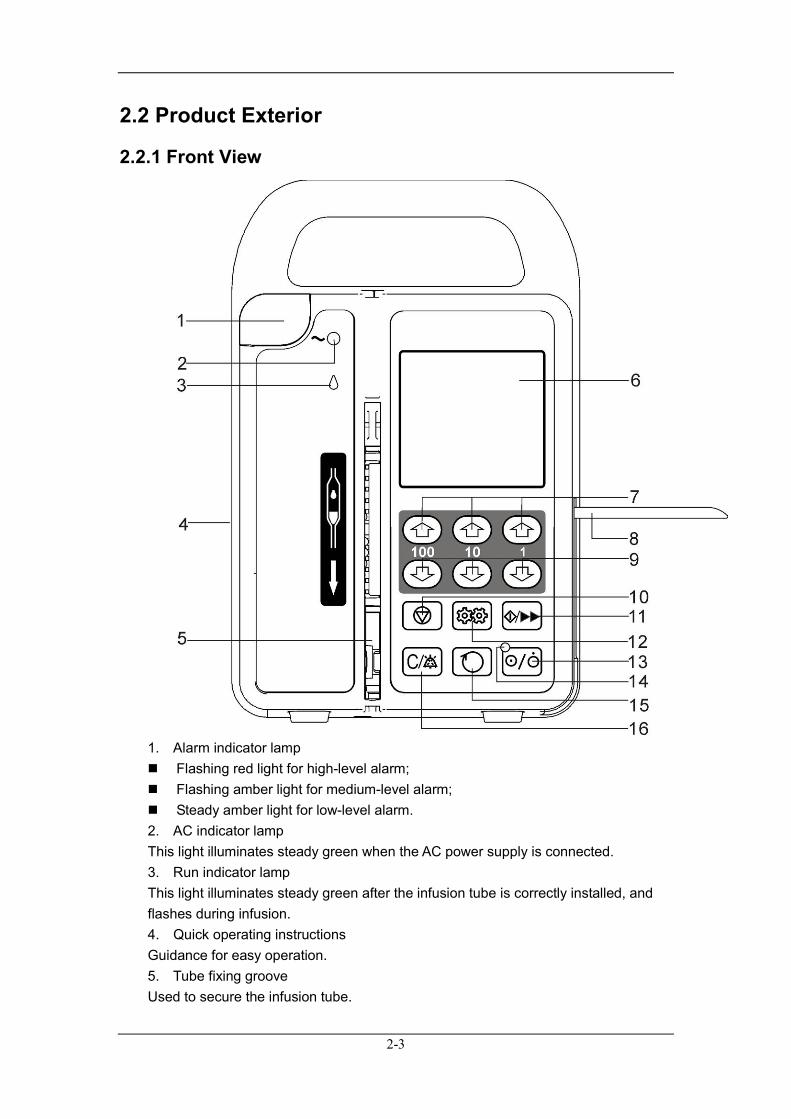
1. Alarm indicator lamp Flashing red light for high-level alarm; Flashing amber light for medium-level alarm; Steady amber light for low-level alarm. 2. AC indicator lamp This light illuminates steady green when the AC power supply is connected. 3. Run indicator lamp This light illuminates steady green after the infusion tube is correctly installed, and flashes during infusion. 4. Quick operating instructions Guidance for easy operation. 5. Tube fixing groove Used to secure the infusion tube.
2-4
6. Display Displays infusion parameters and running status. 7. UP key Moves cursor up or increases value in increments of100, 10 or 1. 8. Handle Pull up the handle:to install or remove the infusion tube. Push down the handle:to tightly clamp the tube and prevent the handle from
protruding at the side.If the infusion tube is correctly installed, the running indicator light will illuminate when the handle is pushed down. Otherwise, reinstall the tube.
9. DOWN key Moves cursor down or decreases value in increments of100, 10 or 1. 10. STOP key During infusion, press this key to stop infusion;when an alarm is on, press this
key to silence the alarm (except battery alarms). In the Accuracy Calibration and Pressure Adjust interfaces, cancels saving the
current setting and exits the interface. 11. START/BOLUS key In stop status, if the infusion tube is correctly installed, pressing this key starts
infusion. During infusion, by keeping your finger on this key as long as you need, the
pump will start the bolus function (flow rate ≤ 600 ml/h). After removing your finger from the key, it will return to the original infusion rate.
12. SET key In stop status, press this key to enter the Infusion Parameters setting interface. 13. Power To turn on the machine:press the key and then release it. To turn off the machine:press and hold until the display flashes for two seconds,
then release. Backlight:after powering on the machine, press this key to switch the display
backlight on/off. 14. POWER ON indicator light This light illuminates steady green in Power On mode. 15. SELECT key In the setting interface for the infusion parameter, press this key to select Rate, Preset volume limit and Bed No. in turn. 16. CLEAR/SILENCE key In the Infusion Stop interface, press this key to clear the accumulated amount; In value inputting status, press this key to clear the input value to the minimum
value; When an alarm occurs in the Run interface, press this key to pause the alarm
tone for 2 mins (except battery alarms).
2-5
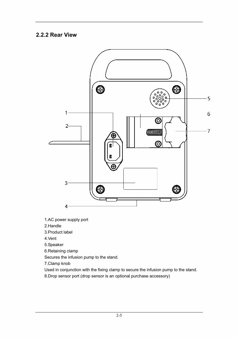
2.2.2 Rear View
1.AC power supply port 2.Handle 3.Product label 4.Vent 5.Speaker 6.Retaining clamp Secures the infusion pump to the stand. 7.Clamp knob Used in conjunction with the fixing clamp to secure the infusion pump to the stand. 8.Drop sensor port (drop sensor is an optional purchase accessory)
2-6
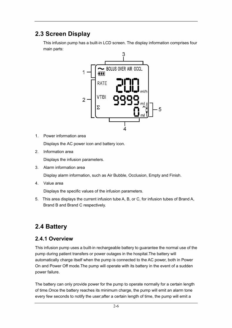
2.3 Screen Display This infusion pump has a built-in LCD screen. The display information comprises four main parts:
1. Power information area
Displays the AC power icon and battery icon.
2. Information area
Displays the infusion parameters.
3. Alarm information area
Display alarm information, such as Air Bubble, Occlusion, Empty and Finish.
4. Value area
Displays the specific values of the infusion parameters.
5. This area displays the current infusion tube A, B, or C, for infusion tubes of Brand A, Brand B and Brand C respectively.
2.4 Battery
2.4.1 Overview This infusion pump uses a built-in rechargeable battery to guarantee the normal use of the pump during patient transfers or power outages in the hospital.The battery will automatically charge itself when the pump is connected to the AC power, both in Power On and Power Off mode.The pump will operate with its battery in the event of a sudden power failure.
The battery can only provide power for the pump to operate normally for a certain length of time.Once the battery reaches its minimum charge, the pump will emit an alarm tone every few seconds to notify the user;after a certain length of time, the pump will emit a
2-7
rapid beeping alarm tone and the alarm indicator light will flash to alert the user that the battery is nearly empty. If the pump is running at this time, it will automatically stop the infusion and will not operate until it is connected to the AC power.The battery empty alarm will only stop sounding after the pump is connected to the AC power.
The alarm indicator light, AC indicator light, AC icon and battery icon all indicate the battery's current status:
When the battery is empty, the red alarm light flashes. When the battery is low, the amber alarm light flashes. When not connected to the AC power supply, the amber alarm light glows
steady and the battery symbol is displayed in the upper-left corner of the screen.
When charging, the AC indicator light glows steady amber and the battery charging icon is displayed in the upper-left corner of the screen.
NOTE
8-14 hours are required to fully charge an empty battery.
Please discharge the battery every 3 months to prevent damage to the battery if the product is not in regular use.
The battery is a consumable part. Please replace it when it no longer holds adequate charge.
If you have any queries, please contact your distributor or the manufacturer.
2.4.2 Battery Guidelines The lifespan of the battery depends on its usage frequency and environment.If it is used and maintained correctly, its lifespan is 3 years.Otherwise, its lifespan will be shortened.The battery will need to be replaced every 3 years.
For safe use and longer battery life, please adhere to the following battery guidelines:
The battery should be checked annually.Before the pump is sent for
maintenance or if you suspect the battery to be the cause of a problem, the battery should be checked.
Optimize the battery every 3 months of use (or storage), or once the battery running time is significantly shortened.
2-8
WARNING
Use the battery specified by the manufacturer.
Please replace the battery immediately if it is damaged or leaking.
Damaged batteries must not be used.
Used batteries must be returned to your supplier or the manufacturer, or disposed of in accordance with applicable laws and regulations.
2.4.3 Battery Maintenance 2.4.3.1 Battery Optimization
Optimize the battery when it is used for the first time.A complete optimizing cycle entails the following:charge continuously until the battery is fully charged, then discharge the battery until the pump powers off automatically, then charge the battery continuously again until fully charged.During usage, regularly optimizing the battery performance will extend its lifespan.
NOTE
The actual battery capacity will reduce after the battery has been used for some time.If the battery capacity is obviously shortened during optimization, please replace the battery.
Please follow the steps below during optimization: 1. Disconnect the infusion pump from the patient, and stop the infusion. 2. Connect the infusion pump to the AC power, charging continuously for 12 hours. 3. Disconnect the infusion pump and the AC power, using the battery as the power
supply until the infusion pump powers off automatically. 4. Connect the infusion pump to the AC power, charging continuously for 12 hours. 5. Battery performance optimization is complete.
2.4.3.2 Checking the Battery
Regular battery checks are required because battery function will reduce as it is used. Please follow the steps below when checking the battery: 1. Connect the pump to the AC power, charging continuously for 8 to 14 hours. 2. Disconnect the AC power supply and let the machine operate on battery power
until it switches off due to the battery being exhausted.

2-9
If the battery works for over 200 mins, it is in good condition. If the battery works for 60 to 200 mins, it is close to the end of its life. If the battery works for less than 60 mins, it has reached the end of its life and
needs to be replaced. 3. Please charge the battery for future usage after performing this check.
NOTE
If the battery’s usage time is too short after a full charge, the battery may be damaged.The battery’s power supply time depends on the usage frequency of the pump and its setting parameters. For example:extended use of the display backlight.
If the battery has obvious damage (e.g. misshapen, dented, leaking) or cannot hold charge, it should be replaced and recycled.
2.4.4 Battery Recycling If the battery has obvious damage (e.g. misshapen, dented, leaking) or the battery capacity is used up, it should be replaced and recycled.Please follow the applicable laws on recycling.
WARNING
The battery must not be disassembled, thrown onto fire or short-circuited.The burning, explosion or leakage of the battery may result in personal injury.

2-10
FOR YOUR NOTES
3-1
3 Installation and Maintenance
3.1 Installation
WARNING
The software copyright of this infusion pump belongs to our company. Any infringement such as falsification, reproduction or exchange by any means or in any form by any organization or individual is prohibited without permission.
3.1.1 Out of Box Audit (OOBA) Before opening the box, please check the packaging carefully for any damage to the products during transportation.If there is any damage, please contact the distributor or our company immediately. If the packaging is intact, please open it immediately, carefully remove the infusion pump and its accessories, and inspect them against the packing list.Examine the pump for any mechanical damage and ensure that the box includes all items on the packing list.Please contact our customer service department immediately if you have any queries.
WARNING
Please keep the packaging materials out of the reach of children.The packaging materials must be disposed of in compliance with local laws and regulations or the hospital policy on waste management.
NOTE
Please keep the packing case and packaging materials for future transport or storage.
Please contact your distributor or the manufacturer if any of the spare parts are missing when you open the box.
3-2
3.1.2 Environmental Requirements The operating environment of this infusion pump must meet the requirements in A.2 Environmental Specifications. The operating environment of this infusion pump should also be appropriately protected from noise, vibration, dust, and corrosive, inflammable or explosive substances.There should be a 2-inch (5 cm) gap around the infusion pump to ensure that air can circulate freely. When the infusion pump is transferred from one place to another, the difference in temperature and humidity may cause condensation to form in the infusion pump. If this is the case, do not switch on the pump until the condensation has gone.
3.1.3 Power Supply Requirements The power supply for this infusion pump must meet the requirements in A.3Power Specifications.
WARNING
Ensure that the operating environment and power supply meet environmental requirements and the power supply requirements specified above. Otherwise, the infusion pump will not meet the technical specifications outlined in A. Product Specifications, and this may also cause unexpected consequences such as damage to the device.
The power supply must be selected in accordance with the settings for the system power voltage.Otherwise, it may cause severe damage to the system.
3-3
3.1.4 Fixing the Infusion Pump
Fig. 3-1
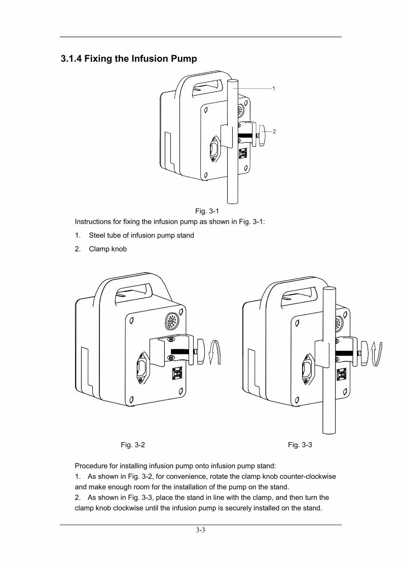
Instructions for fixing the infusion pump as shown in Fig. 3-1:
1. Steel tube of infusion pump stand
2. Clamp knob
Fig. 3-2 Fig. 3-3 Procedure for installing infusion pump onto infusion pump stand: 1. As shown in Fig. 3-2, for convenience, rotate the clamp knob counter-clockwise and make enough room for the installation of the pump on the stand. 2. As shown in Fig. 3-3, place the stand in line with the clamp, and then turn the clamp knob clockwise until the infusion pump is securely installed on the stand.

3-4
NOTE
The infusion pump must be installed horizontally.
Please ensure the stand is stable before installation.
3.1.5 Installing the Power Cord Plug the power cord into the socket on the machine.
NOTE
Applicable power supply range is: 100–240 V, 50/60 Hz.
The AC power cable should be inserted correctly and tightly.
When the infusion pump is not connected to the AC power, it will emit a pip sound every few seconds to remind the user to connect the AC power.
3.1.6 Installing the Drop Sensor (optional)
NOTE
This section should be used with the optional drop sensor. The user may skip the instructions in this section if a drop sensor is not included with the infusion pump.
The drop sensor function can only be started when the rate ≤ 400 ml/h.
3-5
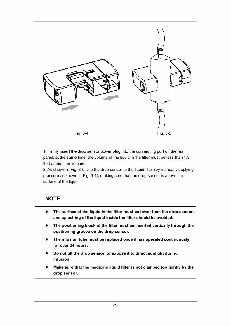
Fig. 3-4 Fig. 3-5
1. Firmly insert the drop sensor power plug into the connecting port on the rear panel; at the same time, the volume of the liquid in the filter must be less than 1/3 that of the filter volume; 2. As shown in Fig. 3-5, clip the drop sensor to the liquid filter (by manually applying pressure as shown in Fig. 3-4), making sure that the drop sensor is above the surface of the liquid.
NOTE
The surface of the liquid in the filter must be lower than the drop sensor, and splashing of the liquid inside the filter should be avoided.
The positioning block of the filter must be inserted vertically through the positioning groove on the drop sensor.
The infusion tube must be replaced once it has operated continuously for over 24 hours.
Do not tilt the drop sensor, or expose it to direct sunlight during infusion.
Make sure that the medicine liquid filter is not clamped too tightly by the drop sensor.
3-6
3.2 Maintenance
WARNING
The hospital or medical facility using this infusion pump must set up a comprehensive maintenance plan. Failure to do so may result in device failure or other unexpected consequences, and may even jeopardize personal safety.
All safety inspections or maintenance work involving the disassembling of the pump must be conducted by professional maintenance personnel. Action by unqualified persons may result in device failure and even jeopardize personal safety.
Please contact your distributor or the manufacturer immediately if you discover any problem with the pump.
3.2.1 Inspection The pump must be given an overall inspection before use, after it has been in continuous use for over 6 months, or after maintenance or updating, so as to ensure that it is operating and functioning normally. The inspection criteria are: The environment and power supply meet requirements The battery performance is good The power cord is not damaged and has sufficient electrical insulation Current leakage meets requirements The infusion pump and accessories have no mechanical damage The accessories used with the pump are specified accessories The alarm system functions correctly Leakage after installation of the infusion tube Pump operates well in all infusion modes If any pump damage or abnormal circumstances occur, please do not use the infusion pump, and contact your distributor or the manufacturer immediately.
3-7
3.2.2 Cleaning and Disinfection The pump must be cleaned or disinfected using the materials and methods listed in this chapter. Otherwise, our company will not be responsible for any damage or accident caused by cleaning and disinfection using other materials and methods. Our company shall not be held responsible for the efficacy of infection control using the following chemicals or methods.Please contact the hospital's infection prevention department or epidemic experts regarding infection control methods. Please keep the infusion pump and accessories free of dust,and comply with the following provisions to prevent damage to the pump: Dilute all cleaning agents and disinfectants in accordance with the
manufacturer’s instructions, or use as low a concentration as possible. Do not submerge the pump in liquid. Do not pour liquid onto the device or its accessories. Avoid liquid entering the pump body. Do not use abrasive materials (such as steel wool or silver polishing agent) or
any strong xylene or acetone-type solvent, in order to prevent damage to the outer casing.
WARNING
Turn off the power and disconnect the AC power supply before cleaning the infusion pump.
CAUTION
If liquid is accidentally spilled on the infusion pump or its accessories and causes the infusion pump to stop working, please contact your distributor or the manufacturer.
The infusion pump should be cleaned regularly. The cleaning frequency should be increased in areas with serious environmental pollution or in very windy or sandy areas.Before cleaning, please consult or refer to the hospital's specific regulations concerning medical device cleaning.
3-8
The recommended cleaning agents and disinfectants are: Warm water Diluted soapy water Diluted aqua ammonia Sodium hypochlorite (bleaching powder for washing) Hydrogen peroxide (3%) Ethanol (70%) Isopropanol (70%) Recommended procedure for cleaning and disinfection: 1.Turn off the power and disconnect the power cord. 2.Use a piece of soft cloth dampened with warm water to wipe the surface of the infusion pump if any liquid is spilled on it. 3.Wipe the surface of the pump with a soft cloth soaked in 70% ethanol. 4.Keep the pump in a cool and ventilated environment to dry. The above steps are for reference only. The effects of disinfection should be checked according to the relevant method.
CAUTION
Do not use ethylene oxide (EtO) gas or formaldehyde for disinfection.
3.2.3 Periodic Maintenance 1. Checking the Infusion Flow Volume Check the infusion flow volume every 3 months using a measuring cylinder and stopwatch.
WARNING
Operators should not rely solely on the infusion pump detection function, but should also use their clinical experience to determine whether the infusion flow rate is normal.
2.Maintaining Battery Performance Refer to 2.4.3 Battery Maintenance. 3.Routine Maintenance

3-9
Interval Routine Maintenance Procedures
According to hospital policy Thoroughly clean the infusion pump casing before or after long storage periods.
Check the pump at least once a year.
1. Check the AC power plug and power cord. 2. Run the machine until it emits a low battery alarm. Then charge the battery to ensure it works and recharges fully. 3. Check for leakage after correct installation of the infusion tube.
3.2.4 Pollution-Free Disposal and Recycling For more relevant information about pollution-free disposal and recycling, please contact your distributor or the manufacturer. You can dispose of the pump and accessories as follows: 1. Pumps that have been scrapped can be sent back to your distributor or the manufacturer for proper recycling. 2. Used batteries can be sent back to your distributor or the manufacturer for disposal, or disposed of in accordance with applicable laws and regulations.

3-10
FOR YOUR NOTES
4-1
4 Operation Guide
4.1 Operation Flow Chart
Turn on the machine
Install the Infusion Set
Start Infusion
Clear the accumulated amount
Infusion Finished
Disconnect the infusion tube between patient and the pump
Set the infusion parameters
Check and remove any air bubbles
Connect the patient and the pump
Turn off the Infusion Pump
Prepare Infusion
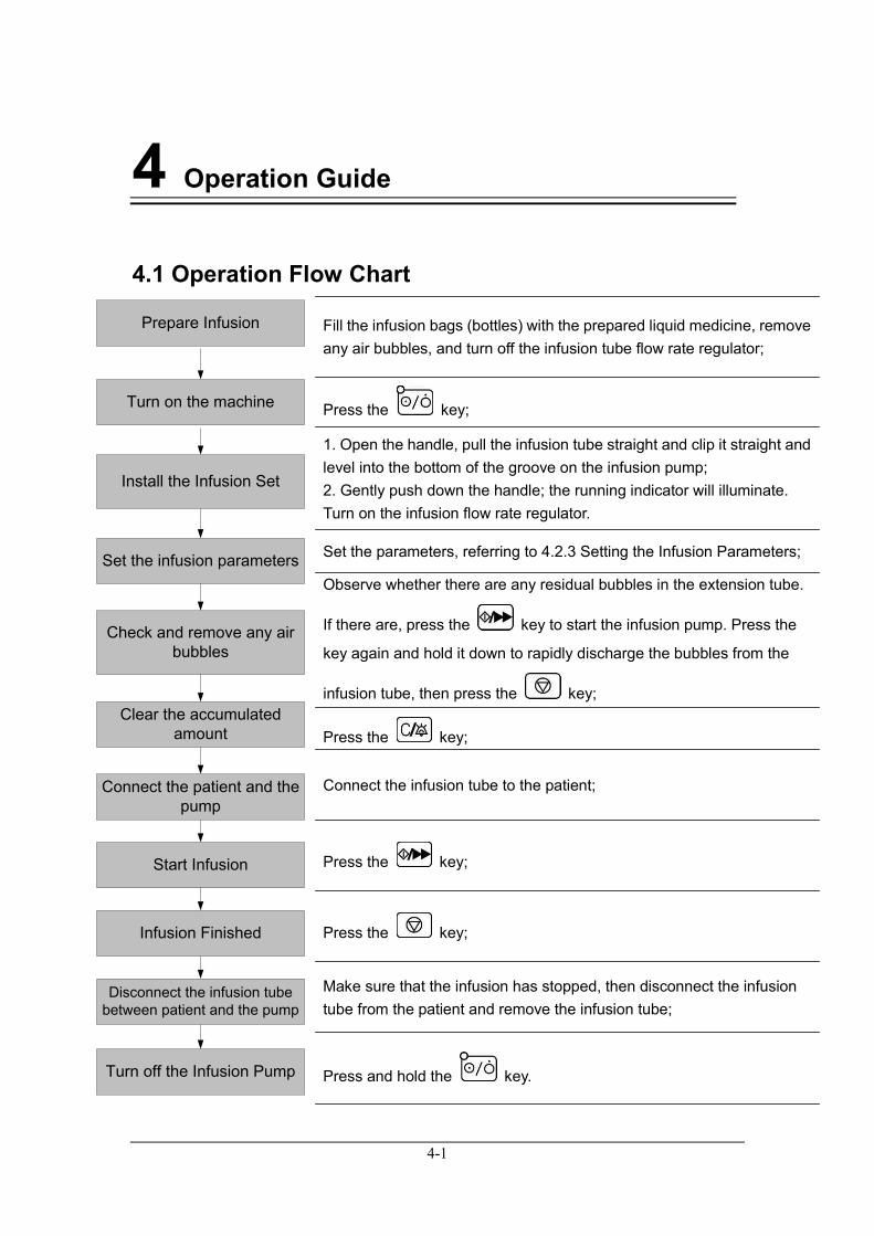
Fill the infusion bags (bottles) with the prepared liquid medicine, remove any air bubbles, and turn off the infusion tube flow rate regulator;
Press the key;
1. Open the handle, pull the infusion tube straight and clip it straight and level into the bottom of the groove on the infusion pump; 2. Gently push down the handle; the running indicator will illuminate. Turn on the infusion flow rate regulator.
Set the parameters, referring to 4.2.3 Setting the Infusion Parameters;
Observe whether there are any residual bubbles in the extension tube.
If there are, press the key to start the infusion pump. Press the
key again and hold it down to rapidly discharge the bubbles from the
infusion tube, then press the key;
Press the key;
Connect the infusion tube to the patient;
Press the key;
Press the key;
Make sure that the infusion has stopped, then disconnect the infusion tube from the patient and remove the infusion tube;
Press and hold the key.
4-2
4.2 Operating Steps
NOTE
Part of this section covers the Drop Sensor function. If the user needs to use this function, the drop sensor should be purchased as an accessory to the infusion pump. For more details, please consult your distributor or the manufacturer.
4.2.1 Turning on the Infusion Pump After installing the infusion pump, turn on the device by referring to the following steps: 1. Perform a safety inspection referring to 3.2.1 Inspection before turning on the
pump.
2. Press the key. The pump will start self-checking and will display the
power-on interface. 3. After a few seconds, the pump will finish self-checking and enter the main
interface. 4. Now the user can operate the pump by means of the operating panel.
NOTE
When the AC indicator light is illuminated, this means that the pump is running on AC power.
In Power On mode, you can turn the display backlight on/off by pressing
the key.
4-3
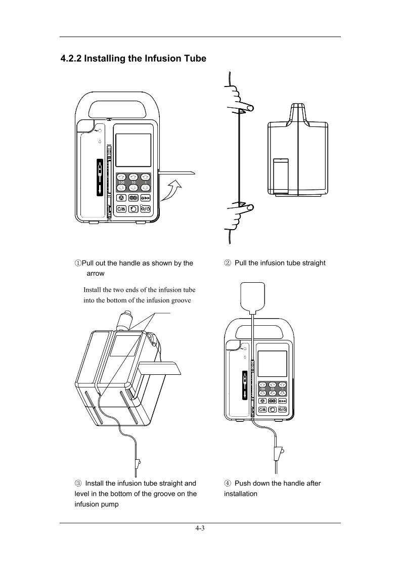
4.2.2 Installing the Infusion Tube
①Pull out the handle as shown by the
arrow
② Pull the infusion tube straight
③ Install the infusion tube straight and level in the bottom of the groove on the infusion pump
④ Push down the handle after installation
Install the two ends of the infusion tube into the bottom of the infusion groove
4-4
WARNING
Push down the handle after correct installation of the infusion tube when the pump is in Power On mode. If the running indicator light illuminates, it means that the infusion tube is correctly installed. If it does not illuminate, the infusion tube needs to be reinstalled.
When using the same infusion tube, change the part of the tube that is clamped in the groove of the machine every 4 hours.The infusion tube must be replaced once it has operated continuously for over 24 hours.
If the infusion tube is loose or pulled too tightly, this may cause an abnormal infusion volume.
The double-layer thickness of the infusion tube should be between 0.8 mm–1.2 mm. The outer diameter should be between 3.5 mm–4.5 mm. Otherwise, its accuracy cannot be guaranteed, and may cause serious injury to patients.
CAUTION
After installation of the infusion tube and before infusion, check for leakages. If any are found, they should be rectified as soon as possible.
4.2.3 Setting the Infusion Parameters
1. Press the key to place the pump in stop status.
2. Press the key to enter the setting interface for the infusion parameters. Press
the key to select Rate, Preset volume limit and Bed No. in turn.The parameter will
keep flashing when it is selected. Press the key or key to adjust the value;
press the key to save the newly set parameter.
4-5
4.2.4 Clearing the Accumulated Volume
In stop status, press the key to clear the accumulated volume.
NOTE
The accumulated volume can only be cleared when the infusion pump is in stop status.
4.2.5 Starting the Infusion After setting all the parameters and installing the infusion tube correctly, press the
key. The motor will begin to run and the pump will start infusing. The running
indicator light will flash during infusion.
NOTE
The pump will stop working automatically once the critically low battery alarm sounds during infusion.
4.2.6 Infusion Finished
When the accumulated volume reaches the preset volume limit, the LCD will display “Finish” and emit an audible alarm to alert the user that the infusion is finished. Press the
key to stop the infusion.
4.2.7 Turning off the Infusion Pump Follow the steps below to turn off the infusion pump:
1. Disconnect the infusion tube between the patient and the pump.
2. Press and hold the key until the backlight blinks for 2 seconds, then release
the key and the pump will power off.

4-6
NOTE
The flow rate and other parameters will reset to the default values after the machine is turned off.
5-1
5 Function and Interface
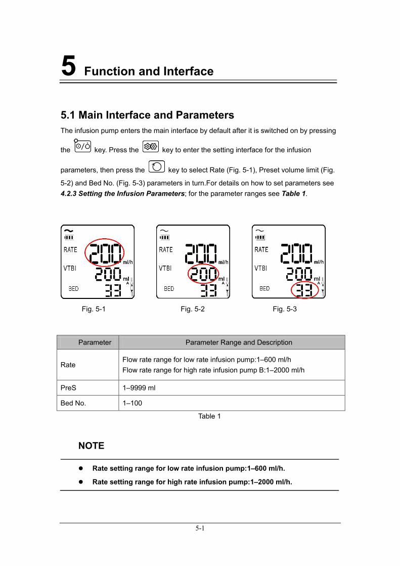
5.1 Main Interface and Parameters The infusion pump enters the main interface by default after it is switched on by pressing
the key. Press the key to enter the setting interface for the infusion
parameters, then press the key to select Rate (Fig. 5-1), Preset volume limit (Fig.
5-2) and Bed No. (Fig. 5-3) parameters in turn.For details on how to set parameters see 4.2.3 Setting the Infusion Parameters; for the parameter ranges see Table 1.
Fig. 5-1 Fig. 5-2 Fig. 5-3
Parameter Parameter Range and Description
Rate Flow rate range for low rate infusion pump:1–600 ml/h Flow rate range for high rate infusion pump B:1–2000 ml/h
PreS 1–9999 ml
Bed No. 1–100
Table 1
NOTE
Rate setting range for low rate infusion pump:1–600 ml/h.
Rate setting range for high rate infusion pump:1–2000 ml/h.

5-2
5.2 Bolus Function During the infusion, if you need to accelerate the infusion when the current flow rate is
below the bolus rate (600 ml/h), keep pressing the key to increase the flow rate to
600 ml/h, and release the key to return to the original flow rate.
NOTE
The bolus function should be used under normal infusion conditions.
The bolus function does not affect any of the alarm functions.
The flow rate for the bolus function is 600 ml/h, and is not adjustable.
5.3 Drop Rate Function and Setting (Optional)
NOTE
The Drop Rate Function described in this section requires software support. For more details, please consult your distributor or the manufacturer.
The pressure adjust and accuracy calibration interfaces do not monitor drop rate.
The drop rate function can only be started when the rate ≤ 400 ml/h.
WARNING
The drop sensor is not applicable to light-proof medicine infusions. Adopting light-proof IV sets on the pumps might cause the drop sensor to fail and result in serious injury to patients.
5-3
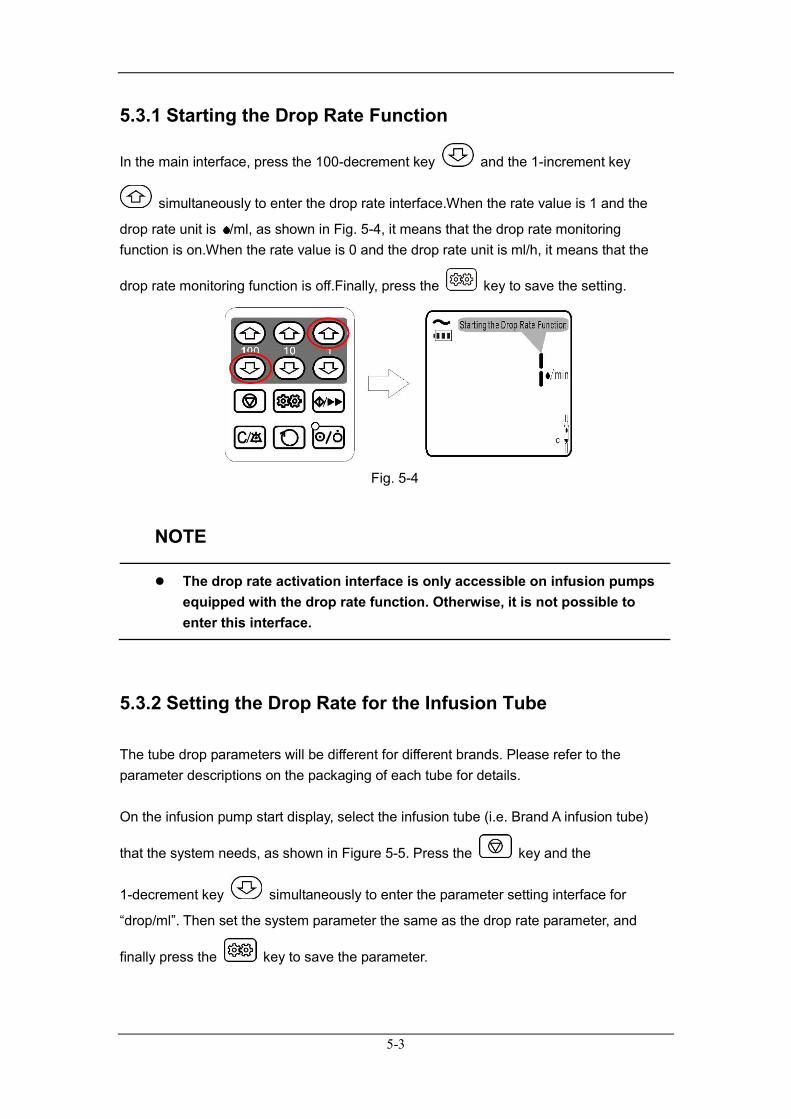
5.3.1 Starting the Drop Rate Function
In the main interface, press the 100-decrement key and the 1-increment key
simultaneously to enter the drop rate interface.When the rate value is 1 and the
drop rate unit is /ml, as shown in Fig. 5-4, it means that the drop rate monitoring function is on.When the rate value is 0 and the drop rate unit is ml/h, it means that the
drop rate monitoring function is off.Finally, press the key to save the setting.
Fig. 5-4
NOTE
The drop rate activation interface is only accessible on infusion pumps equipped with the drop rate function. Otherwise, it is not possible to enter this interface.
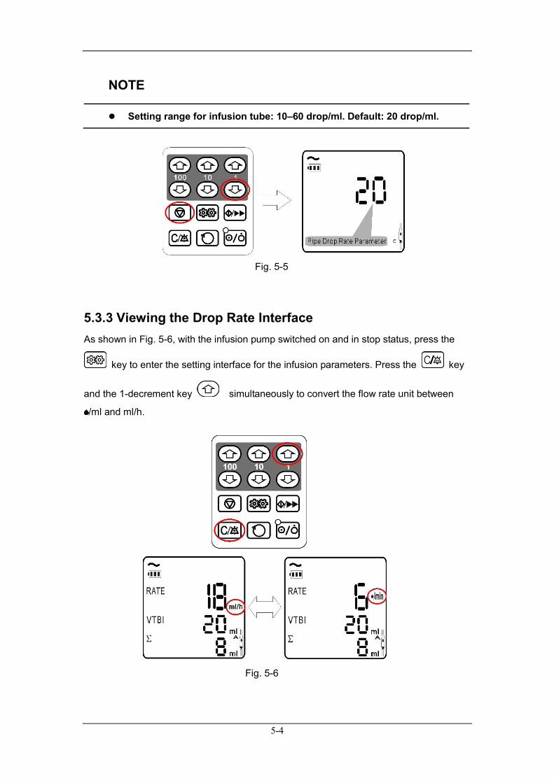
5.3.2 Setting the Drop Rate for the Infusion Tube The tube drop parameters will be different for different brands. Please refer to the parameter descriptions on the packaging of each tube for details.
On the infusion pump start display, select the infusion tube (i.e. Brand A infusion tube)
that the system needs, as shown in Figure 5-5. Press the key and the
1-decrement key simultaneously to enter the parameter setting interface for
“drop/ml”. Then set the system parameter the same as the drop rate parameter, and
finally press the key to save the parameter.
5-4
NOTE
Setting range for infusion tube: 10–60 drop/ml. Default: 20 drop/ml.
Fig. 5-5
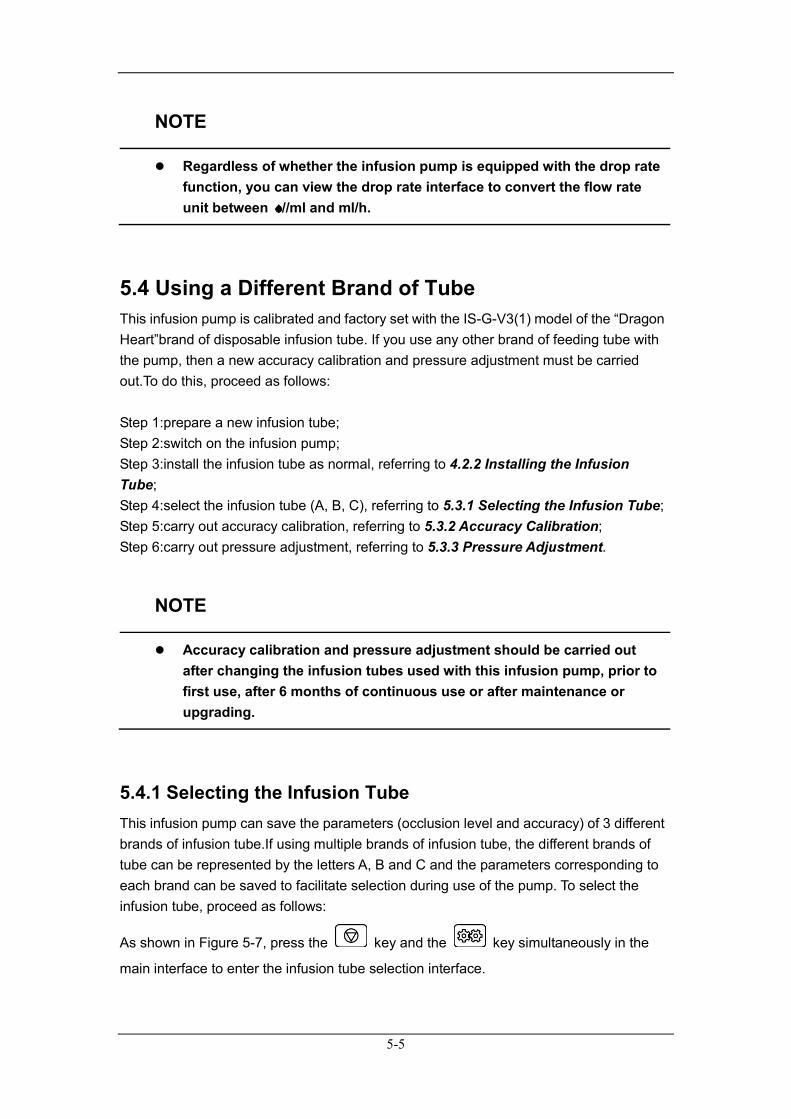
5.3.3 Viewing the Drop Rate Interface As shown in Fig. 5-6, with the infusion pump switched on and in stop status, press the
key to enter the setting interface for the infusion parameters. Press the key
and the 1-decrement key simultaneously to convert the flow rate unit between
/ml and ml/h.
Fig. 5-6
5-5
NOTE
Regardless of whether the infusion pump is equipped with the drop rate function, you can view the drop rate interface to convert the flow rate unit between //ml and ml/h.
5.4 Using a Different Brand of Tube This infusion pump is calibrated and factory set with the IS-G-V3(1) model of the “Dragon Heart”brand of disposable infusion tube. If you use any other brand of feeding tube with the pump, then a new accuracy calibration and pressure adjustment must be carried out.To do this, proceed as follows:
Step 1:prepare a new infusion tube; Step 2:switch on the infusion pump; Step 3:install the infusion tube as normal, referring to 4.2.2 Installing the Infusion Tube; Step 4:select the infusion tube (A, B, C), referring to 5.3.1 Selecting the Infusion Tube; Step 5:carry out accuracy calibration, referring to 5.3.2 Accuracy Calibration; Step 6:carry out pressure adjustment, referring to 5.3.3 Pressure Adjustment.
NOTE
Accuracy calibration and pressure adjustment should be carried out after changing the infusion tubes used with this infusion pump, prior to first use, after 6 months of continuous use or after maintenance or upgrading.
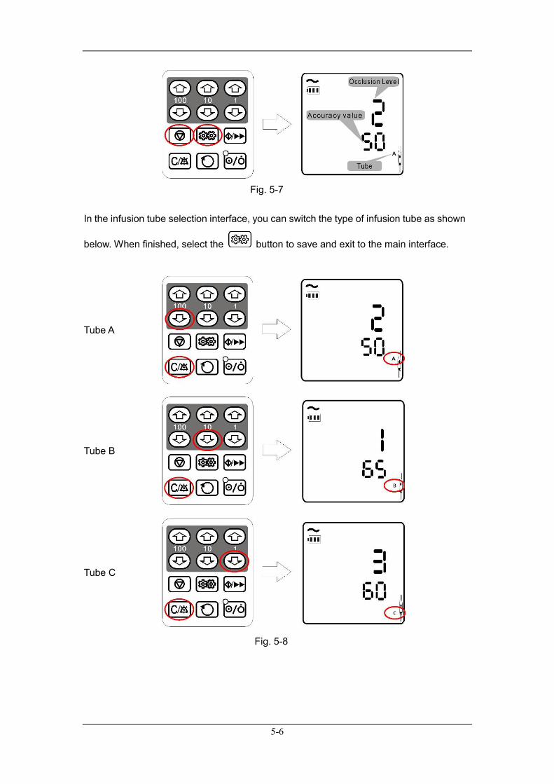
5.4.1 Selecting the Infusion Tube This infusion pump can save the parameters (occlusion level and accuracy) of 3 different brands of infusion tube.If using multiple brands of infusion tube, the different brands of tube can be represented by the letters A, B and C and the parameters corresponding to each brand can be saved to facilitate selection during use of the pump. To select the infusion tube, proceed as follows:
As shown in Figure 5-7, press the key and the key simultaneously in the
main interface to enter the infusion tube selection interface.
5-6
Fig. 5-7
In the infusion tube selection interface, you can switch the type of infusion tube as shown
below. When finished, select the button to save and exit to the main interface.
Tube A
Tube B
Tube C
Fig. 5-8
5-7
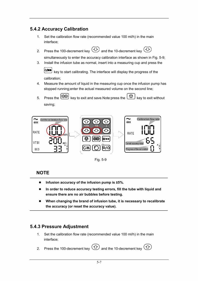
5.4.2 Accuracy Calibration 1. Set the calibration flow rate (recommended value 100 ml/h) in the main
interface;
2. Press the 100-decrement key and the 10-decrement key
simultaneously to enter the accuracy calibration interface as shown in Fig. 5-9; 3. Install the infusion tube as normal, insert into a measuring cup and press the
key to start calibrating. The interface will display the progress of the
calibration; 4. Measure the amount of liquid in the measuring cup once the infusion pump has
stopped running;enter the actual measured volume on the second line;
5. Press the key to exit and save.Note:press the key to exit without
saving;
Fig. 5-9
NOTE
Infusion accuracy of the infusion pump is ±5%.
In order to reduce accuracy testing errors, fill the tube with liquid and ensure there are no air bubbles before testing.
When changing the brand of infusion tube, it is necessary to recalibrate the accuracy (or reset the accuracy value).
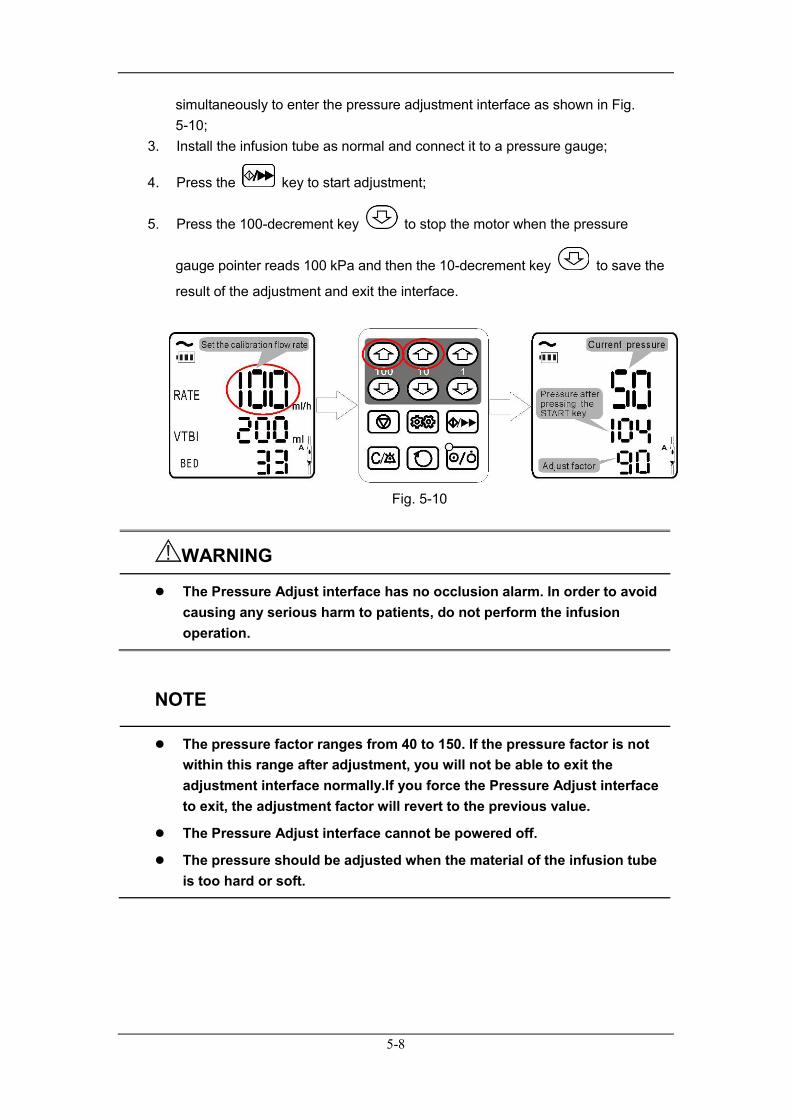
5.4.3 Pressure Adjustment 1. Set the calibration flow rate (recommended value 100 ml/h) in the main
interface;
2. Press the 100-decrement key and the 10-decrement key
5-8
simultaneously to enter the pressure adjustment interface as shown in Fig. 5-10;
3. Install the infusion tube as normal and connect it to a pressure gauge;
4. Press the key to start adjustment;
5. Press the 100-decrement key to stop the motor when the pressure
gauge pointer reads 100 kPa and then the 10-decrement key to save the
result of the adjustment and exit the interface.
Fig. 5-10
WARNING
The Pressure Adjust interface has no occlusion alarm. In order to avoid causing any serious harm to patients, do not perform the infusion operation.
NOTE
The pressure factor ranges from 40 to 150. If the pressure factor is not within this range after adjustment, you will not be able to exit the adjustment interface normally.If you force the Pressure Adjust interface to exit, the adjustment factor will revert to the previous value.
The Pressure Adjust interface cannot be powered off.
The pressure should be adjusted when the material of the infusion tube is too hard or soft.
5-9
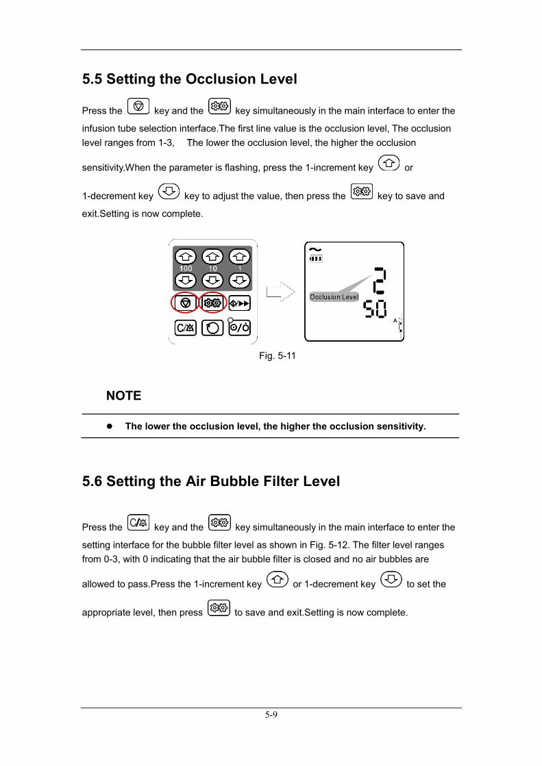
5.5 Setting the Occlusion Level
Press the key and the key simultaneously in the main interface to enter the
infusion tube selection interface.The first line value is the occlusion level, The occlusion level ranges from 1-3, The lower the occlusion level, the higher the occlusion
sensitivity.When the parameter is flashing, press the 1-increment key or
1-decrement key key to adjust the value, then press the key to save and
exit.Setting is now complete.
Fig. 5-11
NOTE
The lower the occlusion level, the higher the occlusion sensitivity.
5.6 Setting the Air Bubble Filter Level
Press the key and the key simultaneously in the main interface to enter the
setting interface for the bubble filter level as shown in Fig. 5-12. The filter level ranges from 0-3, with 0 indicating that the air bubble filter is closed and no air bubbles are
allowed to pass.Press the 1-increment key or 1-decrement key to set the
appropriate level, then press to save and exit.Setting is now complete.

5-10
Fig. 5-12
NOTE
The higher the filter level, the larger the capacity of air bubble allowed through the filter.
5.7 Automatic Pressure Release Function (Anti-Bolus) If occlusion occurs during infusion, an occlusion alarm will be triggered. The motor will reverse and pressure will be released automatically.The motor will remain in reverse until the pressure limit is reached.
5.8 KVO Function When infusion is finished, the system automatically enters KVO mode, continues running at a flow rate of 1 ml/h, and displays the infusion finished report and KVO Rate.
If no operation is performed and no alarm is triggered after entering KVO mode, the system automatically stops after running at the KVO rate for half an hour. Otherwise, it will stop during this process.

6-1
6 Alarms
6.1 Overview Alarms refer to the use of both sound and information displays to alert health care workers to any abnormalities in the infusion circuit or any faults occurring with the infusion pump itself during the infusion process, affecting the pump's ability to provide smooth infusion to the patient.
WARNING
It is potentially hazardous to use the same or similar equipment with different alarm presets within the same area.
6.2 Alarm Levels and Methods When an alarm occurs, the infusion pump will use both visual and auditory methods to alert the user: Visual alarm Audible alarm Alarm Information The visual alarm and audible alarm will vary in order to identify the different alarm types.
Alarm method Alarm level
Visual alarm Audible alarm Message display
Color On Off Sound Continuous Intermittent Text display Prompt
type
High-level alarms
Red 250 ms
250 ms
dididi-didi …… dididi-didi
3000 ms 10 s
Air Bubble Finish Occlusion Battery Empty (not displayed) SystemError:Err 1 Motor Error:Err 2 Drops Error:Err 3 HandleOpen:Err 4
Single alarm flashing; multiple alarms displayed alternately; information switching frequency is 1 s
Mid-level alarms
Yellow 500 ms
500 ms
dididi …… dididi
1500 ms 15 s Reminder:Err 5 Low Battery (not displayed)
Low-level alarms
Yellow Steady / di…… 500 ms 20 s AC Disconnect (not displayed)
6-2
6.3 Pausing the Alarm Tone
After a pump alarm is triggered during infusion, press the key to pause the
alarm tone for 2 mins (except battery alarms). If the source of the alarm has not been eliminated after 2 mins, the alarm tone will continue to sound.
6.4 Alarm Countermeasures
WARNING
Please check the patient’s condition first when an alarm occurs.
When an alarm is triggered, please refer to the following steps and take appropriate measures: 1. Inspect the patient; 2. Confirm the parameters or type of alarm; 3. Determine the reason for the alarm; 4. Eliminate the reason for the alarm; 5. Check whether the alarm has cleared.
NOTE
Please refer to C - Alarm Information for the specific handling measures for each alarm.
A-1
A Product Specifications
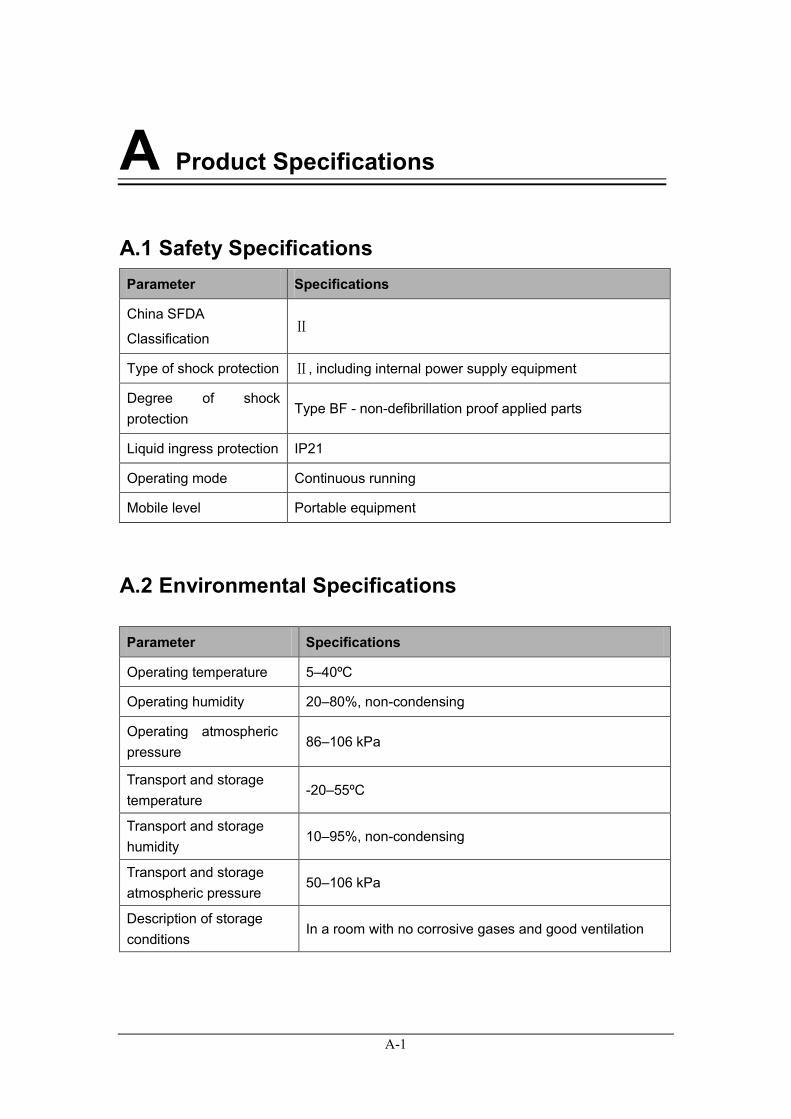
A.1 Safety Specifications Parameter Specifications
China SFDA
Classification Ⅱ
Type of shock protection Ⅱ, including internal power supply equipment
Degree of shock protection
Type BF - non-defibrillation proof applied parts
Liquid ingress protection IP21
Operating mode Continuous running
Mobile level Portable equipment
A.2 Environmental Specifications
Parameter Specifications
Operating temperature 5–40ºC
Operating humidity 20–80%, non-condensing
Operating atmospheric pressure
86–106 kPa
Transport and storage temperature
-20–55ºC
Transport and storage humidity
10–95%, non-condensing
Transport and storage atmospheric pressure
50–106 kPa
Description of storage conditions
In a room with no corrosive gases and good ventilation
A-2
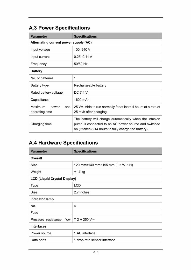
A.3 Power Specifications Parameter Specifications
Alternating current power supply (AC)
Input voltage 100–240 V
Input current 0.25–0.11 A
Frequency 50/60 Hz
Battery
No. of batteries 1
Battery type Rechargeable battery
Rated battery voltage DC 7.4 V
Capacitance 1600 mAh
Maximum power and operating time
25 VA. Able to run normally for at least 4 hours at a rate of 25 ml/h after charging.
Charging time The battery will charge automatically when the infusion pump is connected to an AC power source and switched on (it takes 8-14 hours to fully charge the battery).
A.4 Hardware Specifications Parameter Specifications
Overall
Size 120 mm×140 mm×195 mm (L × W × H)
Weight ≈1.7 kg
LCD (Liquid Crystal Display)
Type LCD
Size 2.7 inches
Indicator lamp
No. 4
Fuse
Pressure resistance, flow
T 2 A 250 V~
Interfaces
Power source 1 AC interface
Data ports 1 drop rate sensor interface
A-3
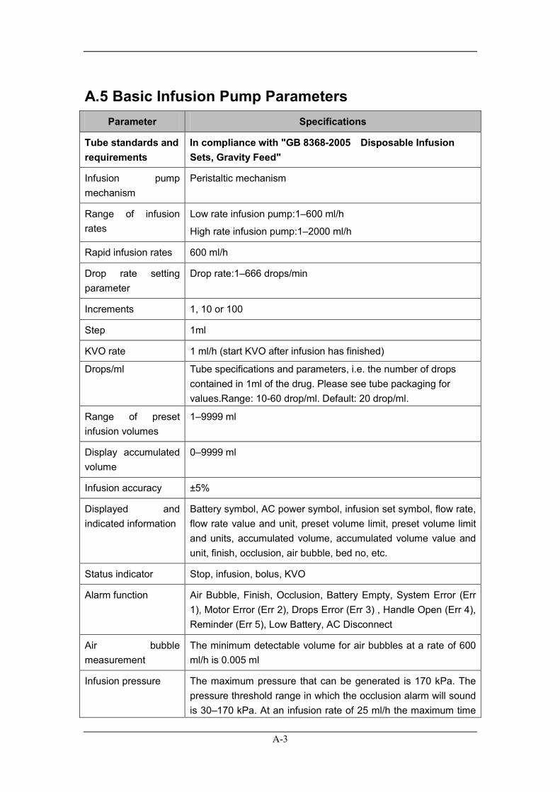
A.5 Basic Infusion Pump Parameters Parameter Specifications
Tube standards and requirements
In compliance with "GB 8368-2005 Disposable Infusion Sets, Gravity Feed"
Infusion pump mechanism
Peristaltic mechanism
Range of infusion rates
Low rate infusion pump:1–600 ml/h
High rate infusion pump:1–2000 ml/h
Rapid infusion rates 600 ml/h
Drop rate setting parameter
Drop rate:1–666 drops/min
Increments 1, 10 or 100
Step 1ml
KVO rate 1 ml/h (start KVO after infusion has finished)
Drops/ml Tube specifications and parameters, i.e. the number of drops contained in 1ml of the drug. Please see tube packaging for values.Range: 10-60 drop/ml. Default: 20 drop/ml.
Range of preset infusion volumes
1–9999 ml
Display accumulated volume
0–9999 ml
Infusion accuracy ±5%
Displayed and indicated information
Battery symbol, AC power symbol, infusion set symbol, flow rate, flow rate value and unit, preset volume limit, preset volume limit and units, accumulated volume, accumulated volume value and unit, finish, occlusion, air bubble, bed no, etc.
Status indicator Stop, infusion, bolus, KVO
Alarm function Air Bubble, Finish, Occlusion, Battery Empty, System Error (Err 1), Motor Error (Err 2), Drops Error (Err 3) , Handle Open (Err 4), Reminder (Err 5), Low Battery, AC Disconnect
Air bubble measurement
The minimum detectable volume for air bubbles at a rate of 600 ml/h is 0.005 ml
Infusion pressure The maximum pressure that can be generated is 170 kPa. The pressure threshold range in which the occlusion alarm will sound is 30–170 kPa. At an infusion rate of 25 ml/h the maximum time
A-4
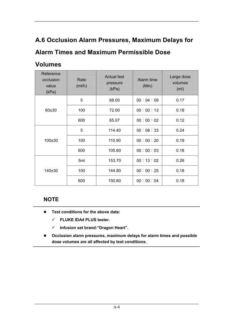
A.6 Occlusion Alarm Pressures, Maximum Delays for
Alarm Times and Maximum Permissible Dose
Volumes Reference occlusion
value (kPa)
Rate (ml/h)
Actual test pressure
(kPa)
Alarm time (Min)
Large dose volumes
(ml)
60±30
5 68.00 00︰04︰09 0.17
100 72.00 00︰00︰13 0.18
600 65.07 00︰00︰02 0.12
100±30
5 114.40 00︰08︰33 0.24
100 110.90 00︰00︰20 0.19
600 105.60 00︰00︰03 0.18
140±30
5ml 153.70 00︰13︰02 0.26
100 144.80 00︰00︰25 0.18
600 150.60 00︰00︰04 0.18
NOTE
Test conditions for the above data:
FLUKE IDA4 PLUS tester.
Infusion set brand:“Dragon Heart”.
Occlusion alarm pressures, maximum delays for alarm times and possible dose volumes are all affected by test conditions.
A-5
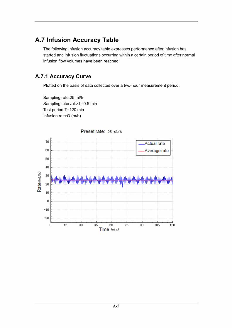
A.7 Infusion Accuracy Table The following infusion accuracy table expresses performance after infusion has started and infusion fluctuations occurring within a certain period of time after normal infusion flow volumes have been reached.
A.7.1 Accuracy Curve Plotted on the basis of data collected over a two-hour measurement period. Sampling rate:25 ml/h Sampling interval:△t =0.5 min Test period:T=120 min Infusion rate:Q (m/h)
A-6
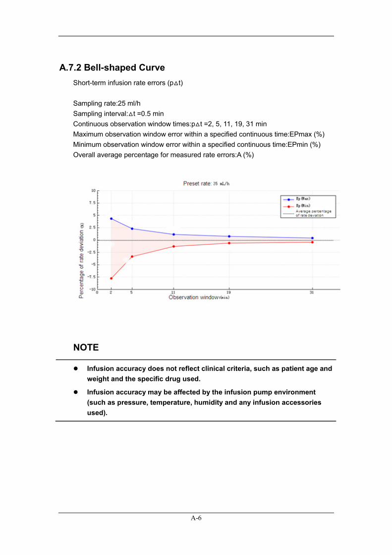
A.7.2 Bell-shaped Curve Short-term infusion rate errors (p△t) Sampling rate:25 ml/h Sampling interval:△t =0.5 min Continuous observation window times:p△t =2, 5, 11, 19, 31 min Maximum observation window error within a specified continuous time:EPmax (%) Minimum observation window error within a specified continuous time:EPmin (%) Overall average percentage for measured rate errors:A (%)
NOTE
Infusion accuracy does not reflect clinical criteria, such as patient age and weight and the specific drug used.
Infusion accuracy may be affected by the infusion pump environment (such as pressure, temperature, humidity and any infusion accessories used).
B-1
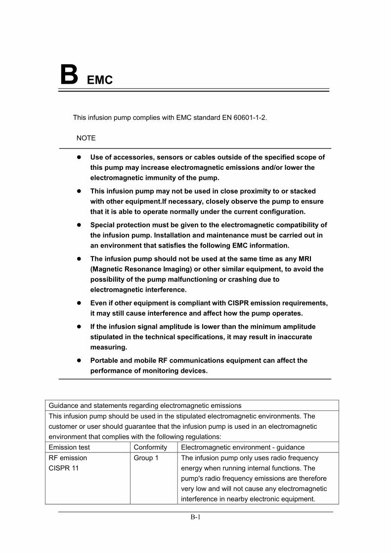
B EMC This infusion pump complies with EMC standard EN 60601-1-2. NOTE
Use of accessories, sensors or cables outside of the specified scope of this pump may increase electromagnetic emissions and/or lower the electromagnetic immunity of the pump.
This infusion pump may not be used in close proximity to or stacked with other equipment.If necessary, closely observe the pump to ensure that it is able to operate normally under the current configuration.
Special protection must be given to the electromagnetic compatibility of the infusion pump. Installation and maintenance must be carried out in an environment that satisfies the following EMC information.
The infusion pump should not be used at the same time as any MRI (Magnetic Resonance Imaging) or other similar equipment, to avoid the possibility of the pump malfunctioning or crashing due to electromagnetic interference.
Even if other equipment is compliant with CISPR emission requirements, it may still cause interference and affect how the pump operates.
If the infusion signal amplitude is lower than the minimum amplitude stipulated in the technical specifications, it may result in inaccurate measuring.
Portable and mobile RF communications equipment can affect the performance of monitoring devices.
Guidance and statements regarding electromagnetic emissions This infusion pump should be used in the stipulated electromagnetic environments. The customer or user should guarantee that the infusion pump is used in an electromagnetic environment that complies with the following regulations: Emission test Conformity Electromagnetic environment - guidance RF emission CISPR 11
Group 1 The infusion pump only uses radio frequency energy when running internal functions. The pump's radio frequency emissions are therefore very low and will not cause any electromagnetic interference in nearby electronic equipment.
B-2
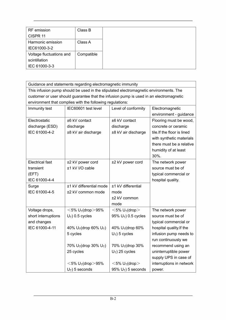
RF emission CISPR 11
Class B
Harmonic emission IEC61000-3-2
Class A
Voltage fluctuations and scintillation IEC 61000-3-3
Compatible
Guidance and statements regarding electromagnetic immunity This infusion pump should be used in the stipulated electromagnetic environments. The customer or user should guarantee that the infusion pump is used in an electromagnetic environment that complies with the following regulations: Immunity test IEC60601 test level Level of conformity Electromagnetic
environment - guidance Electrostatic discharge (ESD) IEC 61000-4-2
±6 kV contact discharge ±8 kV air discharge
±6 kV contact discharge ±8 kV air discharge
Flooring must be wood, concrete or ceramic tile.If the floor is lined with synthetic materials there must be a relative humidity of at least 30%.
Electrical fast transient (EFT) IEC 61000-4-4
±2 kV power cord ±1 kV I/O cable
±2 kV power cord
The network power source must be of typical commercial or hospital quality.
Surge IEC 61000-4-5
±1 kV differential mode ±2 kV common mode
±1 kV differential mode ±2 kV common mode
Voltage drops, short interruptions and changes IEC 61000-4-11
<5% UT(drop>95% UT) 0.5 cycles 40% UT(drop 60% UT) 5 cycles 70% UT(drop 30% UT) 25 cycles <5% UT(drop>95% UT) 5 seconds
<5% UT(drop>95% UT) 0.5 cycles 40% UT(drop 60% UT) 5 cycles 70% UT(drop 30% UT) 25 cycles <5% UT(drop>95% UT) 5 seconds
The network power source must be of typical commercial or hospital quality.If the infusion pump needs to run continuously we recommend using an uninterruptible power supply UPS in case of interruptions in network power.
B-3
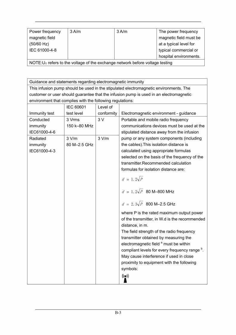
Power frequency magnetic field (50/60 Hz) IEC 61000-4-8
3 A/m 3 A/m The power frequency magnetic field must be at a typical level for typical commercial or hospital environments.
NOTE:UT refers to the voltage of the exchange network before voltage testing
Guidance and statements regarding electromagnetic immunity This infusion pump should be used in the stipulated electromagnetic environments. The customer or user should guarantee that the infusion pump is used in an electromagnetic environment that complies with the following regulations:
Immunity test IEC 60601 test level
Level of conformity Electromagnetic environment - guidance
Conducted immunity IEC61000-4-6
3 Vrms 150 k–80 MHz
3 V Portable and mobile radio frequency communications devices must be used at the stipulated distance away from the infusion pump or any system components (including the cables).This isolation distance is calculated using appropriate formulas selected on the basis of the frequency of the transmitter.Recommended calculation formulas for isolation distance are:
Pd 2.1=
Pd 2.1= 80 M–800 MHz
Pd 3.2= 800 M–2.5 GHz
where P is the rated maximum output power of the transmitter, in W.d is the recommended distance, in m. The field strength of the radio frequency transmitter obtained by measuring the electromagnetic field a must be within compliant levels for every frequency range b. May cause interference if used in close proximity to equipment with the following symbols:
Radiated immunity IEC61000-4-3
3 V/m 80 M–2.5 GHz
3 V/m
B-4
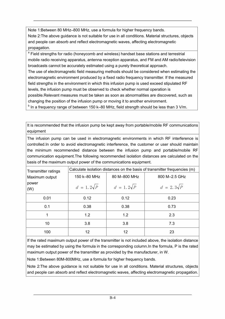
Note 1:Between 80 MHz–800 MHz, use a formula for higher frequency bands. Note 2:The above guidance is not suitable for use in all conditions. Material structures, objects and people can absorb and reflect electromagnetic waves, affecting electromagnetic propagation. a Field strengths for radio (honeycomb and wireless) handset base stations and terrestrial mobile radio receiving apparatus, antenna reception apparatus, and FM and AM radio/television broadcasts cannot be accurately estimated using a purely theoretical approach. The use of electromagnetic field measuring methods should be considered when estimating the electromagnetic environment produced by a fixed radio frequency transmitter. If the measured field strengths in the environment in which this infusion pump is used exceed stipulated RF levels, the infusion pump must be observed to check whether normal operation is possible.Relevant measures must be taken as soon as abnormalities are discovered, such as changing the position of the infusion pump or moving it to another environment. b In a frequency range of between 150 k–80 MHz, field strength should be less than 3 V/m.
It is recommended that the infusion pump be kept away from portable/mobile RF communications equipment
The infusion pump can be used in electromagnetic environments in which RF interference is controlled.In order to avoid electromagnetic interference, the customer or user should maintain the minimum recommended distance between the infusion pump and portable/mobile RF communication equipment.The following recommended isolation distances are calculated on the basis of the maximum output power of the communications equipment.
Transmitter ratings Maximum output power (W)
Calculate isolation distances on the basis of transmitter frequencies (m)
150 k–80 MHz
Pd 2.1=
80 M–800 MHz
Pd 2.1=
800 M–2.5 GHz
Pd 3.2=
0.01 0.12 0.12 0.23
0.1 0.38 0.38 0.73
1 1.2 1.2 2.3
10 3.8 3.8 7.3
100 12 12 23
If the rated maximum output power of the transmitter is not included above, the isolation distance may be estimated by using the formula in the corresponding column.In the formula, P is the rated maximum output power of the transmitter as provided by the manufacturer, in W.
Note 1:Between 80M-800MHz, use a formula for higher frequency bands.
Note 2:The above guidance is not suitable for use in all conditions. Material structures, objects and people can absorb and reflect electromagnetic waves, affecting electromagnetic propagation.
C-1
C Alarm Information
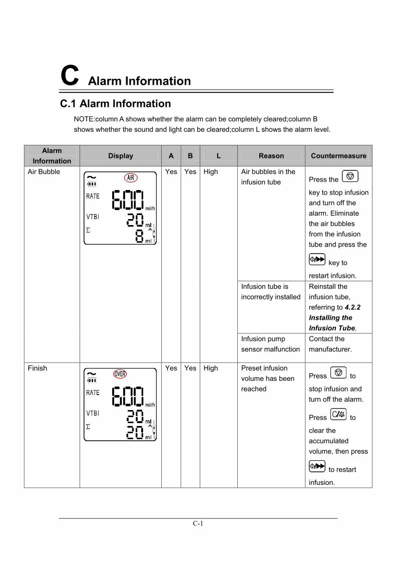
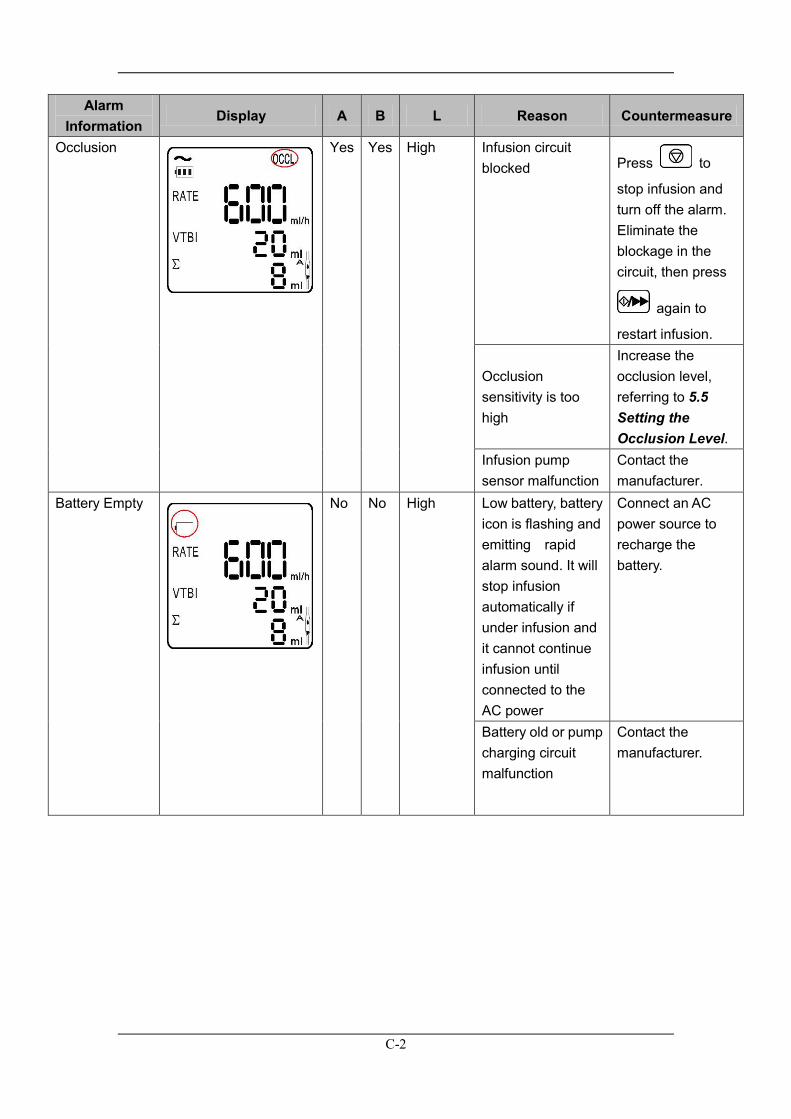
C.1 Alarm Information NOTE:column A shows whether the alarm can be completely cleared;column B shows whether the sound and light can be cleared;column L shows the alarm level.
Alarm Information
Display A B L Reason Countermeasure
Air Bubble
Yes Yes High Air bubbles in the infusion tube Press the
key to stop infusion and turn off the alarm. Eliminate the air bubbles from the infusion tube and press the
key to
restart infusion. Infusion tube is incorrectly installed
Reinstall the infusion tube, referring to 4.2.2 Installing the Infusion Tube.
Infusion pump sensor malfunction
Contact the manufacturer.
Finish
Yes Yes High Preset infusion volume has been reached
Press to
stop infusion and turn off the alarm.
Press to
clear the accumulated volume, then press
to restart
infusion.
C-2
Alarm Information
Display A B L Reason Countermeasure
Occlusion
Yes Yes High Infusion circuit blocked
Press to
stop infusion and turn off the alarm. Eliminate the blockage in the circuit, then press
again to
restart infusion.
Occlusion sensitivity is too high
Increase the occlusion level, referring to 5.5 Setting the Occlusion Level.
Infusion pump sensor malfunction
Contact the manufacturer.
Battery Empty
No No High Low battery, battery icon is flashing and emitting rapid alarm sound. It will stop infusion automatically if under infusion and it cannot continue infusion until connected to the AC power
Connect an AC power source to recharge the battery.
Battery old or pump charging circuit malfunction
Contact the manufacturer.
C-3
Alarm Information
Display A B L Reason Countermeasure
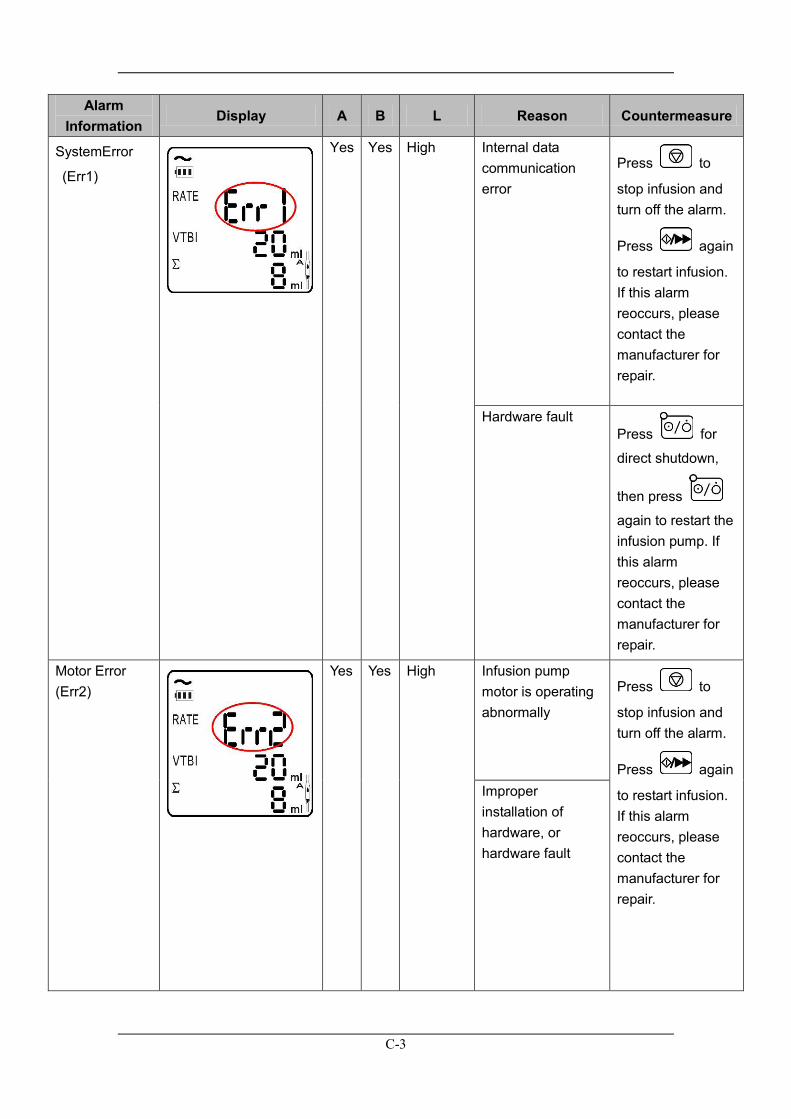
SystemError
(Err1)
Yes Yes High Internal data communication error
Press to
stop infusion and turn off the alarm.
Press again
to restart infusion. If this alarm reoccurs, please contact the manufacturer for repair.
Hardware fault Press for
direct shutdown,
then press
again to restart the infusion pump. If this alarm reoccurs, please contact the manufacturer for repair.
Motor Error (Err2)
Yes Yes High Infusion pump motor is operating abnormally
Press to
stop infusion and turn off the alarm.
Press again
to restart infusion. If this alarm reoccurs, please contact the manufacturer for repair.
Improper installation of hardware, or hardware fault

C-4
Alarm Information
Display A B L Reason Countermeasure
Drops Error (Err3) (requires optional drop rate sensor)
Yes Yes High Error with the drop rate parameter settings
Reset the drop rate parameters correctly.
Accuracy is not calibrated
Recalibrate tube accuracy.
Running the pump for long periods causes water droplets to form on the funnel walls, affecting the monitoring capability of the drop rate sensor
Shake the water droplets off the funnel walls.
Liquid not flowing freely within the tube
Eliminate blockage in the infusion circuit.
Drop rate sensor is faulty
Contact the manufacturer.
Liquid medicine level in the funnel is above the drop rate sensor
Lower the liquid level of the funnel appropriately to keep it below the drop rate sensor.The liquid medicine in the medicine filter must be less than 1/3 of its volume.
Handle Open (Err4)
Yes Yes High Handle open during infusion Press to
stop infusion and turn off the alarm. Close the handle
and press to
restart infusion.
C-5
Alarm Information
Display A B L Reason Countermeasure
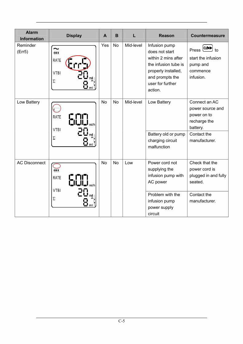
Reminder (Err5)
Yes No Mid-level Infusion pump does not start within 2 mins after the infusion tube is properly installed, and prompts the user for further action.
Press to
start the infusion pump and commence infusion.
Low Battery
No No Mid-level Low Battery Connect an AC power source and power on to recharge the battery.
Battery old or pump charging circuit malfunction
Contact the manufacturer.
AC Disconnect
No No Low Power cord not supplying the infusion pump with AC power
Check that the power cord is plugged in and fully seated.
Problem with the infusion pump power supply circuit
Contact the manufacturer.

C-6
C.2 Prompt Messages None
D-1
D Symbols and Terms
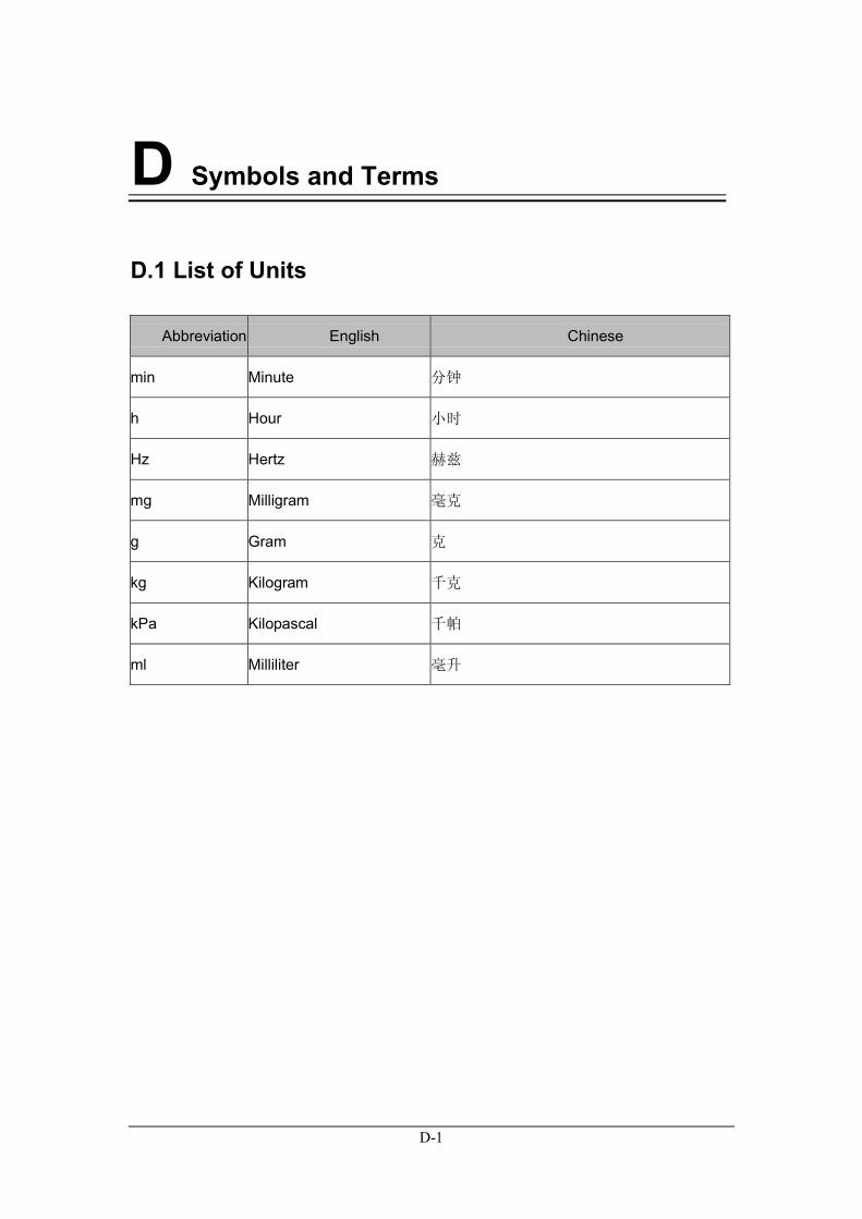
D.1 List of Units
Abbreviation English Chinese
min Minute 分钟
h Hour 小时
Hz Hertz 赫兹
mg Milligram 毫克
g Gram 克
kg Kilogram 千克
kPa Kilopascal 千帕
ml Milliliter 毫升
D-2
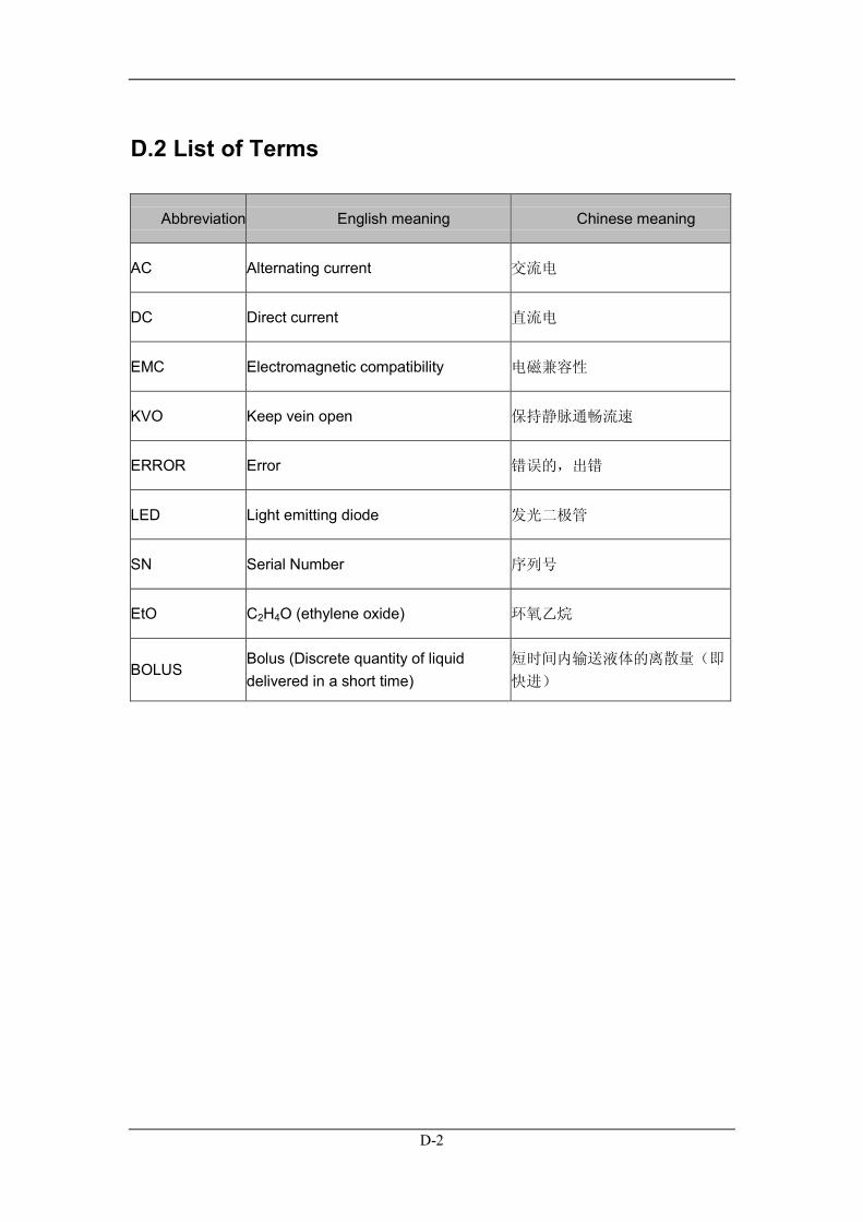
D.2 List of Terms
Abbreviation English meaning Chinese meaning
AC Alternating current 交流电
DC Direct current 直流电
EMC Electromagnetic compatibility 电磁兼容性
KVO Keep vein open 保持静脉通畅流速
ERROR Error 错误的,出错
LED Light emitting diode 发光二极管
SN Serial Number 序列号
EtO C2H4O (ethylene oxide) 环氧乙烷
BOLUS Bolus (Discrete quantity of liquid delivered in a short time)
短时间内输送液体的离散量(即
快进)