INFUB Conference Industrial Furnaces Boilers, INFUB · INFUB ‐11th European Conference on...
26
Technology for a better society 1 INFUB ‐ 11th European Conference on Industrial Furnaces and Boilers, INFUB‐11 Francisco Carrasco‐Maldonado a , Jørn Bakken b , Mario Ditaranto b , Nils E. L. Haugen b , Øyvind Langørgen b , Simon Grathwohl a , Jörg Maier a a IFK, University of Stuttgart, Pfaffenwaldring 23, 70569 Stuttgart, Germany b SINTEF Energy Research, Trondheim, Norway Oxy‐fuel burner investigations for CO2 capture in cement plants
Transcript of INFUB Conference Industrial Furnaces Boilers, INFUB · INFUB ‐11th European Conference on...

Technology for a better society
1
INFUB ‐ 11th European Conference on Industrial Furnaces and Boilers, INFUB‐11
Francisco Carrasco‐Maldonadoa , Jørn Bakkenb, Mario Ditarantob, Nils E. L. Haugenb, Øyvind Langørgenb, Simon Grathwohla, Jörg Maiera
aIFK, University of Stuttgart, Pfaffenwaldring 23, 70569 Stuttgart, GermanybSINTEF Energy Research, Trondheim, Norway
Oxy‐fuel burner investigations for CO2 capture in cement plants

Technology for a better society
2
Raw meal
Cyclonepreheater
Flue gas
Calciner
Tertiary air duct
Cooler exhasut gas
Fuel/air
Fuel
Cooler
Cooling air
Rotary kiln 2000 °C
300 ‐ 350 °C
700 ‐ 1000 °C
200 °C ‐ 350 °C
850 °C
700 ‐ 1000 °C
Clinker
60 % Material CO2
40 % Fuel CO2CaCO3, SiO2, Al2O3, Fe2O3
Cement emissionsrepresent 5% of
total anthropogenicCO2 emissions
CO2 emissions in the cement industry
Source: ECRA
Technology for a better society
3
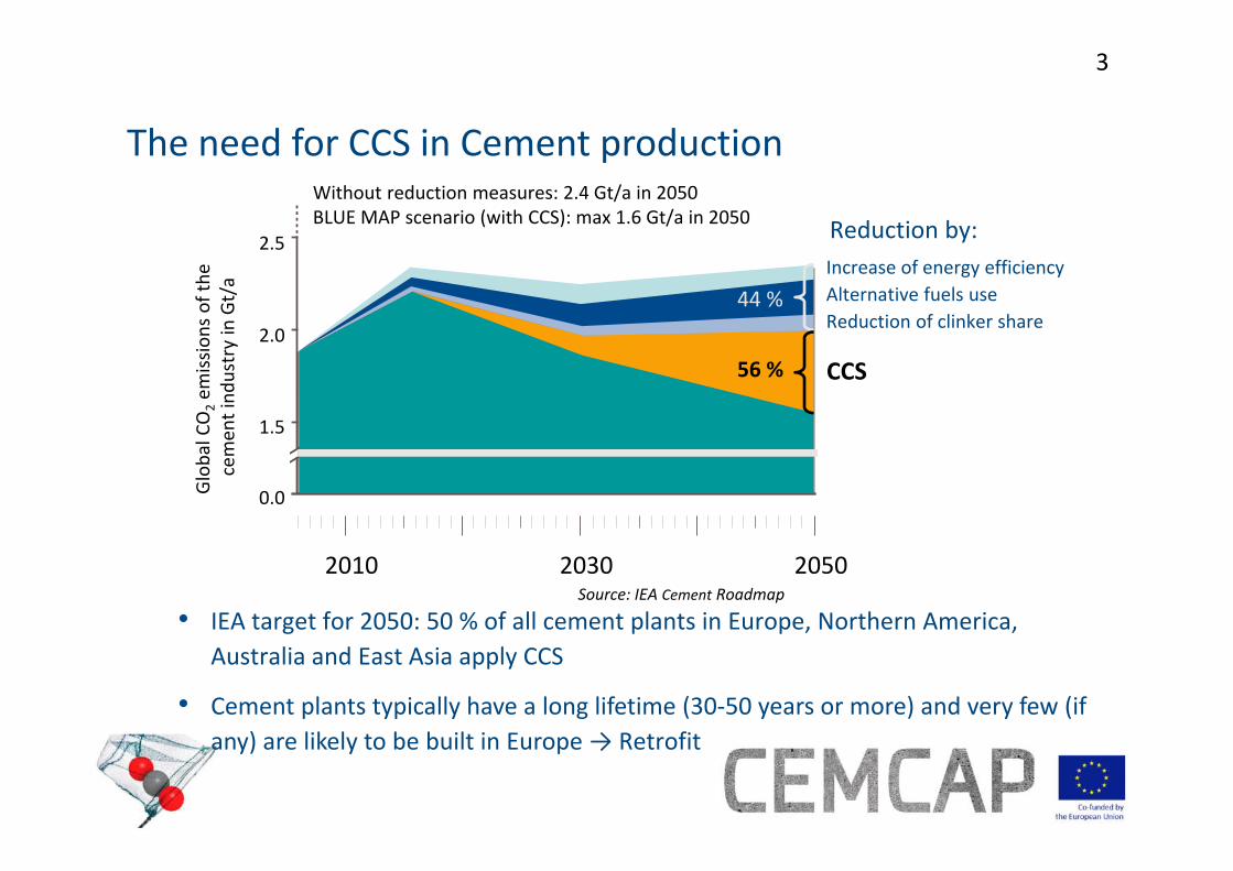
The need for CCS in Cement productionWithout reduction measures: 2.4 Gt/a in 2050BLUE MAP scenario (with CCS): max 1.6 Gt/a in 2050
Increase of energy efficiencyAlternative fuels useReduction of clinker share
Reduction by:
CCS
2.5
2.0
1.5
Global CO2em
issions ofthe
cemen
tind
ustryin Gt/a
0.0
2010 2030 2050
44 %
56 %
Source: IEA Cement Roadmap
• IEA target for 2050: 50 % of all cement plants in Europe, Northern America, Australia and East Asia apply CCS
• Cement plants typically have a long lifetime (30‐50 years or more) and very few (if any) are likely to be built in Europe→ Retrofit
Technology for a better society
4
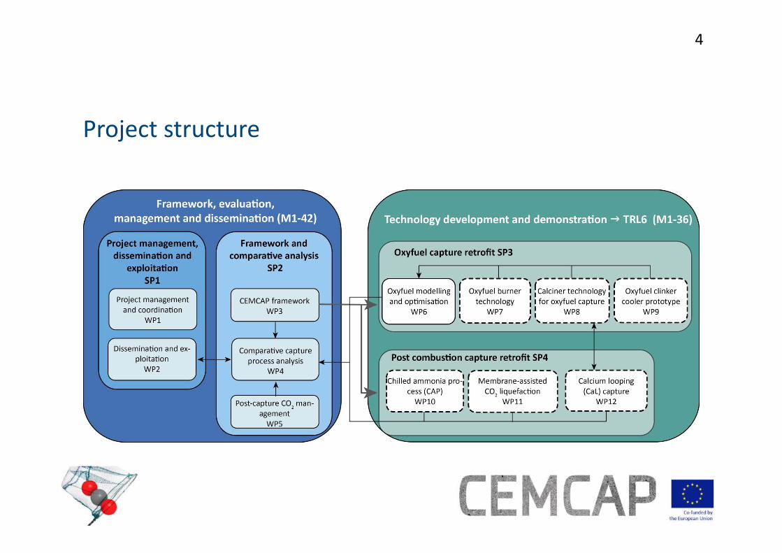
Project structure

Technology for a better society
5
Technologies to be tested ‐ oxyfuelCalciner test rigExisting <50 kWth entrained flow calciner (USTUTT) to be used for oxyfuel calcination tests
Clinker cooler To be designed and built for on‐site testing at HeidelbergCement in Hannover
Partners: USTUTT, VDZ, IKN, CTG
Partners: IKN, HeidelC, VDZ
Partners: USTUTT, TKIS, SINTEF‐ER
Oxyfuel burner Existing 500 kWth oxyfuelburner at USTUTT to be modified for CEMCAP
Source: ECRA

Technology for a better society
6
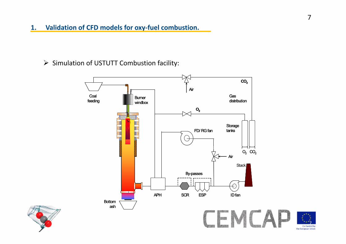
1. Validation of CFD models for oxy‐fuel combustion.
2. Adaptation of test facility for cement kiln burner investigations.
3. Preliminary results of oxy‐fuel investigations.
Outline
Technology for a better society
7
7
Simulation of USTUTT Combustion facility:
1. Validation of CFD models for oxy‐fuel combustion.
Bottomash
ID fanESPSCR
StoragetanksFD/ RG fan
O2
CO2
Stack
AirO2 CO2
Gasdistribution
APH
Coal feeding
Burnerwindbox
Air
By-passes
Bottomash
ID fanESPSCR
StoragetanksFD/ RG fan
O2
CO2
Stack
AirO2 CO2
Gasdistribution
APH
Coal feeding
Burnerwindbox
Air
By-passes
Technology for a better society
8
8
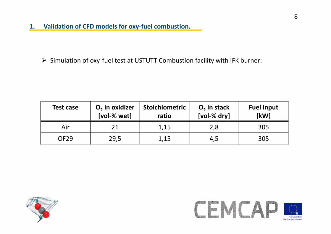
Simulation of oxy‐fuel test at USTUTT Combustion facility with IFK burner:
1. Validation of CFD models for oxy‐fuel combustion.
Test case O2 in oxidizer[vol‐% wet]
Stoichiometricratio
O2 in stack[vol‐% dry]
Fuel input[kW]
Air 21 1,15 2,8 305
OF29 29,5 1,15 4,5 305

Technology for a better society
9
9
South African coal:
1. Validation of CFD models for oxy‐fuel combustion.
0.002.004.006.008.0010.0012.0014.0016.0018.0020.0022.0024.0026.0028.0030.00
0.00
10.00
20.00
30.00
40.00
50.00
60.00
70.00
80.00
90.00
100.00
1.00 10.00 100.00 1000.00
Vol
ume-
%
Particle size [um]
CD
D[v,0.5](um)
BD
Water
[%]
Ash[%]
Volatiles
[%]
Cfix[%]
C[%]
Htot
[%]
H[%]
N[%]
S[%]
O[%]
an 1,65 14,36 27,22 56,77 67,83 4,77 4,59 1,77 0,44 9,35raw 8,94 13,30 25,20 52,56 62,80 5,25 4,25 1,64 0,41 8,66wf - 14,61 27,67 57,72 68,97 4,67 4,67 1,80 0,45 9,51
Ho,v[J/g]
Hu,p[J/g]
an 27.383 26.355raw 25.444 24.316wf 27.942 26.943waf 32.721 31.551Ho,v = HHV and Hu,p = LHV
Technology for a better society
10
10
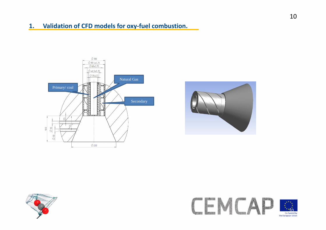
1. Validation of CFD models for oxy‐fuel combustion.
Primary/ coal
Secondary
Natural Gas
Technology for a better society
11
11
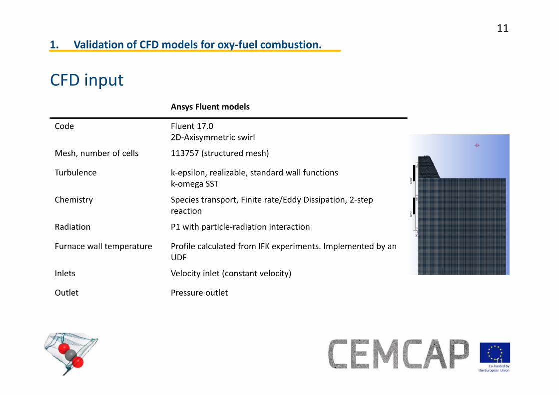
CFD input
1. Validation of CFD models for oxy‐fuel combustion.
Ansys Fluent models
Code Fluent 17.02D‐Axisymmetric swirl
Mesh, number of cells 113757 (structured mesh)
Turbulence k‐epsilon, realizable, standard wall functionsk‐omega SST
Chemistry Species transport, Finite rate/Eddy Dissipation, 2‐step reaction
Radiation P1 with particle‐radiation interaction
Furnace wall temperature Profile calculated from IFK experiments. Implemented by an UDF
Inlets Velocity inlet (constant velocity)
Outlet Pressure outlet
Technology for a better society
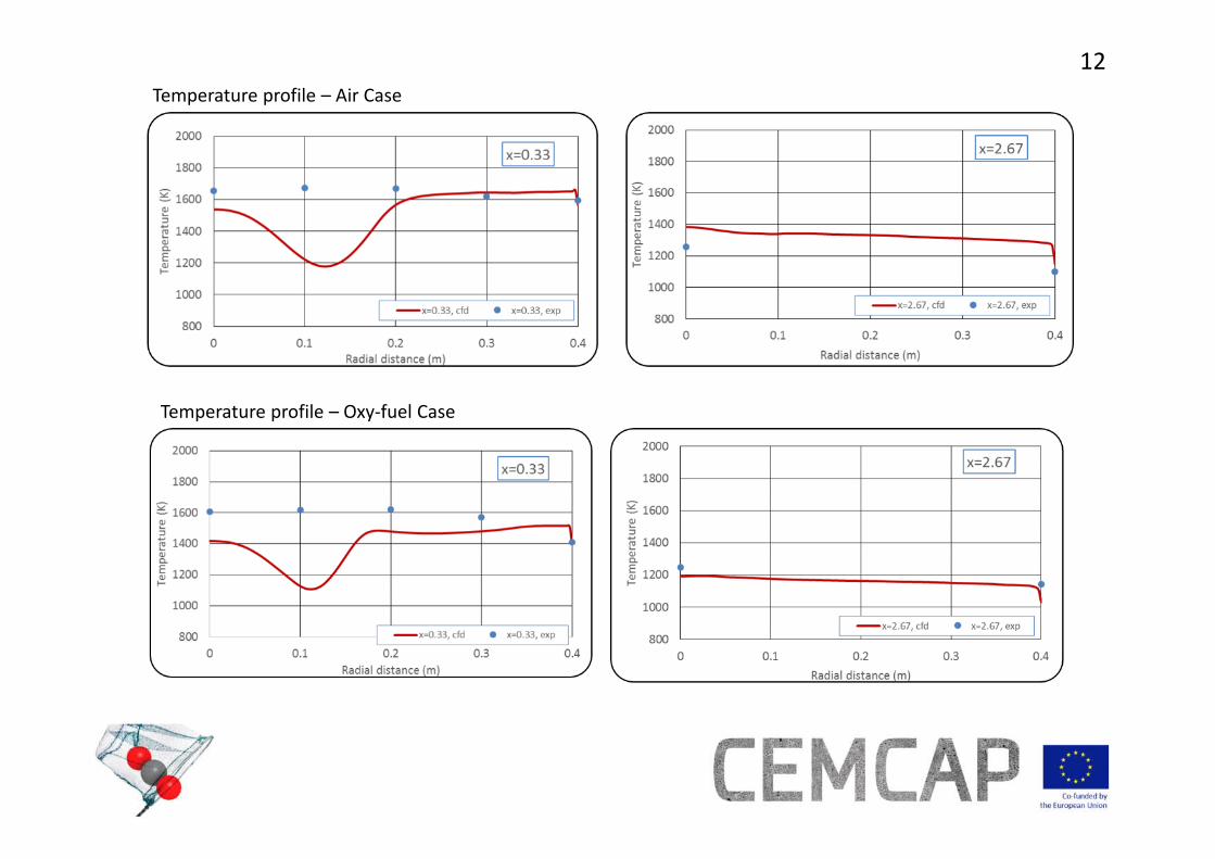
12Temperature profile – Air Case
Temperature profile – Oxy‐fuel Case

Technology for a better society
13Oxygen profile – Oxy‐fuel Case
Carbon dioxide– Oxy‐fuel Case
Technology for a better society
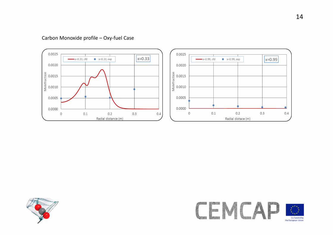
14
Carbon Monoxide profile – Oxy‐fuel Case

Technology for a better society
15
Source: ThyssenKrupp
a) Design of a prototype oxy‐fuel burner for cement kilns.
Source: ThyssenKrupp‐ POLFLAME
2. Adaptation of test facility for cement kiln burner investigations.
• Scaling factor of 100 between industrial and pilot burner.

Technology for a better society
16
16
• Primary Gas (nozzles)o Velocity ca. 250 m/so 8 nozzleso Angle: 0‐40°
• Carrier gas (outer coal channel)o Transport air velocity ca. 15 m/s
2. Adaptation of test facility for cement kiln burner investigations.
Technology for a better society
17
17
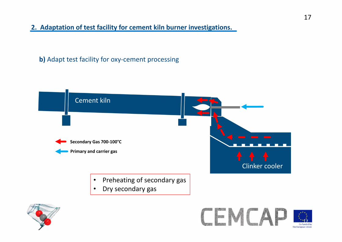
b) Adapt test facility for oxy‐cement processing
2. Adaptation of test facility for cement kiln burner investigations.
Clinker cooler
Cement kiln
Secondary Gas 700‐100°C
Primary and carrier gas
• Preheating of secondary gas• Dry secondary gas
Technology for a better society
18
18
level no.
12345
6789
10
1112131415
1617181920
21
22
23
24
25
26
27
28
29
30
31
Continue gas measurements
Bottomash
ID fanESPSCR
StoragetanksFD/ RG fan
O2
CO2
Stack
AirO2 CO2
Gasdistribution
APH
Coal feeding
Burnerwindbox
Air
By-passes
Bottomash
ID fanESPSCR
StoragetanksFD/ RG fan
O2
CO2
Stack
AirO2 CO2
Gasdistribution
APH
Coal feeding
Burnerwindbox
Air
By-passes
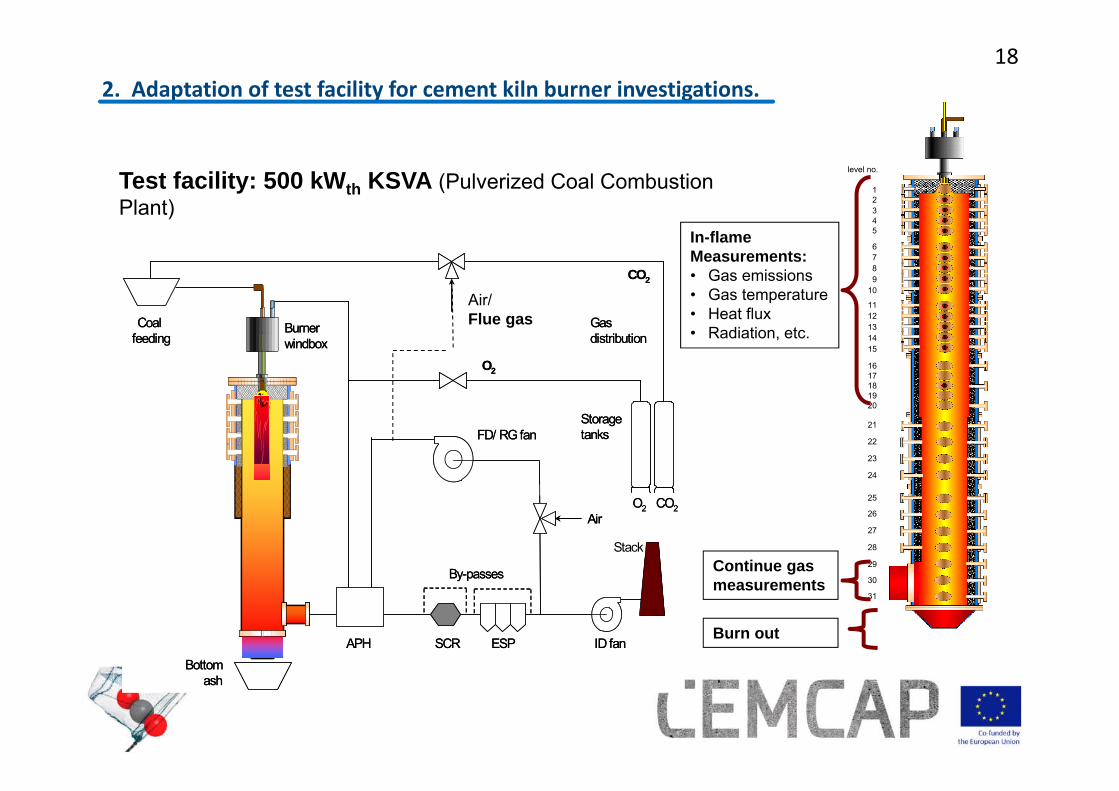
In-flameMeasurements:• Gas emissions• Gas temperature• Heat flux• Radiation, etc.
Air/Flue gas
Test facility: 500 kWth KSVA (Pulverized Coal Combustion Plant)
Burn out
2. Adaptation of test facility for cement kiln burner investigations.
Technology for a better society
19
19Bottom Ash
ID fanESPSCR
Storage Tanks
Carrier gasCO2
Stack
O2 CO2
Coal feeding
Air
By-passes
CO2, O2
Air
Air
CO2, O2
Primary gas
Secondary gas
Preheaters
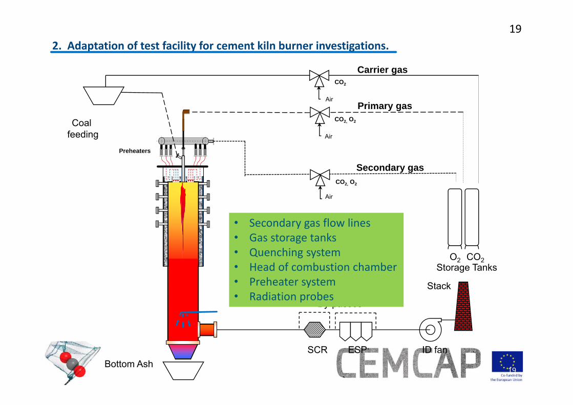
• Secondary gas flow lines• Gas storage tanks• Quenching system• Head of combustion chamber• Preheater system• Radiation probes
2. Adaptation of test facility for cement kiln burner investigations.
Technology for a better society
20
20
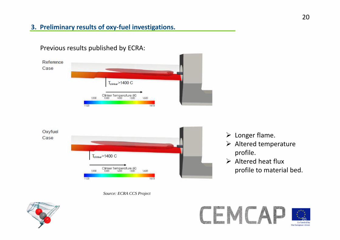
Source: ECRA CCS Project
3. Preliminary results of oxy‐fuel investigations.
Longer flame. Altered temperature
profile. Altered heat flux
profile to material bed.
Previous results published by ECRA:
Technology for a better society
21
21
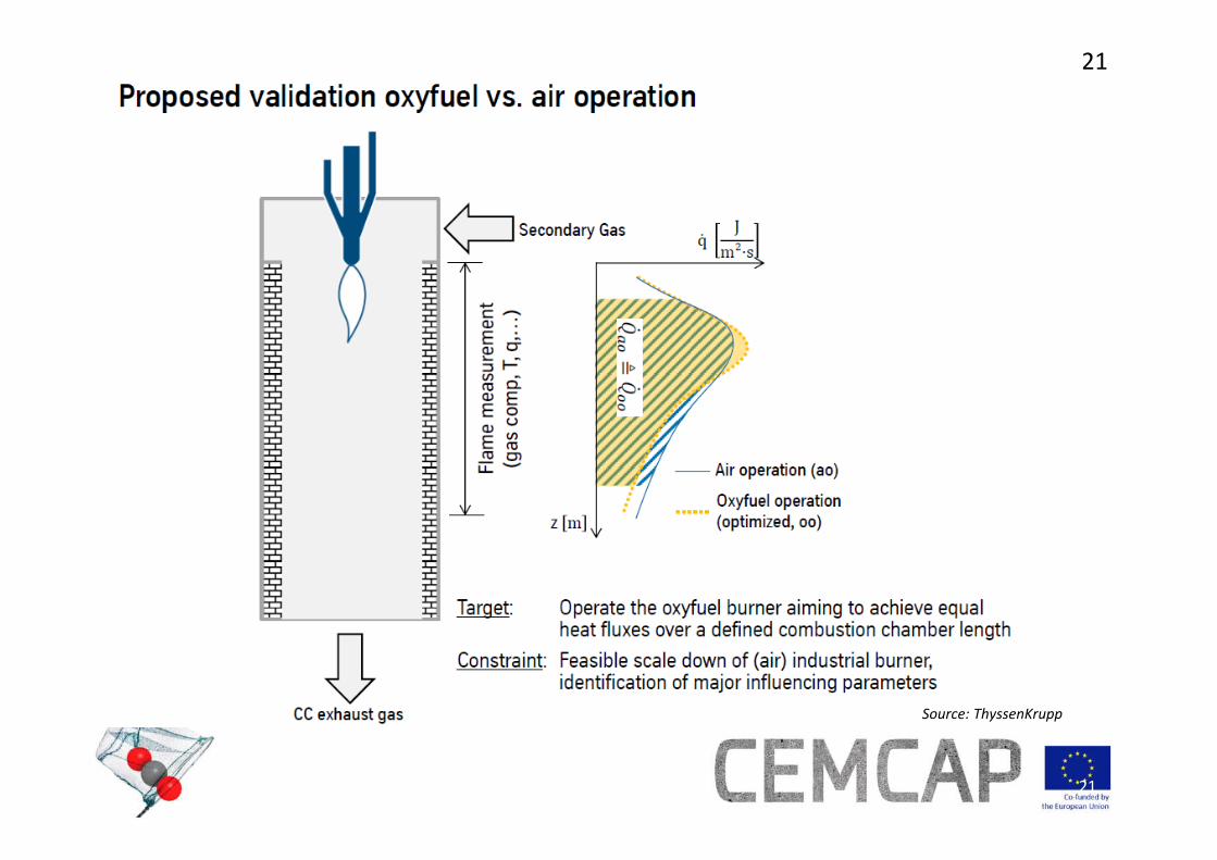
Source: ThyssenKrupp

Technology for a better society
22
22
3. Preliminary results of oxy‐fuel investigations.
Ho,v[J/g]
Hu,p[J/g]
an 33.077 32.237wf 34.657 33.894Ho,v = HHV and Hu,p = LHV
Water[%]
Ash[%]
Volatiles[%]
Cfix[%]
C[%]
Htot
[%]
H[%]
N[%]
S[%]
Cl[%]
an 4,56 2,12 11,3 82,0 77,0 3,91 3,40 1,47 3,03 0,074wf ‐ 2,22 11,9 85,9 80,7 3,56 3,56 1,57 3,17 0,078
Fuel characterization: Petcoke

Technology for a better society
23
23
Primary gas (nozzles)
Coal + Carrier gas
482 kW
Secondary gas
T = 740 °C
v = 4,5 m/s
O2 = 21%
N2 = 79%
λ = 1,12
O2 = 2,2% vol,dry
CO2= 16,5% vol,dry
NOx = 536 ppm, dry
Flue gas
CC Shell radiation
PG = 21%
Primary gas (nozzles)
Coal + Carrier gas
482 kW
O2 = 53%
CO2 = 47%CO2 =100%
Secondary gas
Flue gas
CC Shell radiation
AIR CASE OXY‐27
T = 712 °C
v = 3 m/s
O2 = 21%
CO2 = 79%
λ = 1,13
O2 = 3,4% vol,dry
CO2= 84,6% vol,dry
NOx = 770 ppm, dry
Swirling 40°
PG = 24%

Technology for a better society
24
24
3. Preliminary results of oxy‐fuel investigations.
Air Case Oxy-fuel
Fuel burnout 98,0 98,3

Technology for a better society
25
25
Summary
• First simulation of test rig. Validation vs Experimental data was successful.• Two turbulence models were tested, K‐Omega produced better results.• Test facility was adapted for relevant oxy‐cement tests.• Burner prototype was designed and tested.• Demonstration tests evinced suitability to obtain similar radiation profiles
under oxy‐fuel conditions.
Further Steps• Additional testing with a higher volatile fuel.• Simulation of additional oxy‐fuel cases not investigated in facility.

Technology for a better society
2626
AcknowledgementsThis project has received funding from the European Union's Horizon 2020
research and innovation programme under grant agreement no 641185
This work was supported by the Swiss State Secretariat for Education, Research and Innovation (SERI) under contract number 15.0160
www.sintef.no/cemcapTwitter: @CEMCAP_CO2