
Infrared Reflectance Imaging for Environmentally Friendly ... not display a currently valid OMB...
45
1 Infrared Reflectance Imaging for Environmentally Friendly Corrosion Inspection Through Organic Coatings Project Number WP-0407 Authors: Mr. John Weir, P.E., Northrop Grumman Corporation Mr. Jack Benfer, NAVAIR Jacksonville FL ESTCP Conference Tempe, AZ 25-29 February 2008
Transcript of Infrared Reflectance Imaging for Environmentally Friendly ... not display a currently valid OMB...

1
Infrared Reflectance Imaging for Environmentally Friendly Corrosion Inspection Through Organic Coatings
Project Number WP-0407
Authors:Mr. John Weir, P.E., Northrop Grumman Corporation
Mr. Jack Benfer, NAVAIR Jacksonville FL
ESTCP ConferenceTempe, AZ
25-29 February 2008

Report Documentation Page Form ApprovedOMB No. 0704-0188
Public reporting burden for the collection of information is estimated to average 1 hour per response, including the time for reviewing instructions, searching existing data sources, gathering andmaintaining the data needed, and completing and reviewing the collection of information. Send comments regarding this burden estimate or any other aspect of this collection of information,including suggestions for reducing this burden, to Washington Headquarters Services, Directorate for Information Operations and Reports, 1215 Jefferson Davis Highway, Suite 1204, ArlingtonVA 22202-4302. Respondents should be aware that notwithstanding any other provision of law, no person shall be subject to a penalty for failing to comply with a collection of information if itdoes not display a currently valid OMB control number.
1. REPORT DATE FEB 2008 2. REPORT TYPE
3. DATES COVERED 00-00-2008 to 00-00-2008
4. TITLE AND SUBTITLE Infrared Reflectance Imaging for Environmentally Friendly CorrosionInspection Through Organic Coatings
5a. CONTRACT NUMBER
5b. GRANT NUMBER
5c. PROGRAM ELEMENT NUMBER
6. AUTHOR(S) 5d. PROJECT NUMBER
5e. TASK NUMBER
5f. WORK UNIT NUMBER
7. PERFORMING ORGANIZATION NAME(S) AND ADDRESS(ES) Northrop Grumman Corporation,2980 Fairview Park Drive,Falls Church,VA,22042
8. PERFORMING ORGANIZATIONREPORT NUMBER
9. SPONSORING/MONITORING AGENCY NAME(S) AND ADDRESS(ES) 10. SPONSOR/MONITOR’S ACRONYM(S)
11. SPONSOR/MONITOR’S REPORT NUMBER(S)
12. DISTRIBUTION/AVAILABILITY STATEMENT Approved for public release; distribution unlimited
13. SUPPLEMENTARY NOTES Surface Finishing and Repair Issues for Sustaining New Military Aircraft Workshop, February 26-28,2008, Tempe, AZ. Sponsored by SERDP/ESTCP.
14. ABSTRACT
15. SUBJECT TERMS
16. SECURITY CLASSIFICATION OF: 17. LIMITATION OF ABSTRACT Same as
Report (SAR)
18. NUMBEROF PAGES
44
19a. NAME OFRESPONSIBLE PERSON
a. REPORT unclassified
b. ABSTRACT unclassified
c. THIS PAGE unclassified
Standard Form 298 (Rev. 8-98) Prescribed by ANSI Std Z39-18
2
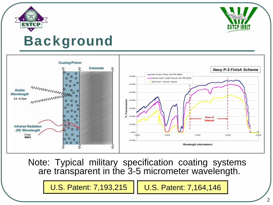
Background
-10.0000
0.0000
10.0000
20.0000
30.0000
40.0000
50.0000
60.0000
70.0000
2.0000 3.0000 4.0000 5.0000 6.0000
Wavelength (micrometers)
% T
rans
mis
sion
Deft 44-GN-7 Primer: MIL-PRF-85582
Hentzen Color # 16440 Topcoat: MIL-PRF-85285
Deft Primer + Hentzen Topcoat
Area of Interest
Navy P-3 Finish Scheme
Note: Typical military specification coating systems are transparent in the 3-5 micrometer wavelength.
U.S. Patent: 7,193,215 U.S. Patent: 7,164,146

3
Technical Objectives• Demonstrate Infrared Reflectance Imaging Technique (IRRIT) as
an enhanced inspection tool when compared to visual inspection.
• Establish and prove the technique and determine cost/waste reductions from actual maintenance operations.
• Reduce environmental impacts • HAZMATs• VOCs• Chromates• Inorganic HAPs
• Reduce costs to inspect and repair coatings by minimizing labor hours and flow/down times.

4
NAVAIR Jacksonville, FL
P-3 OML Dem/Val
Oklahoma City ALC, OK
KC-135 and B-52 IML Dem/Val
P-3 Painted (Prior to Chemical Stripping)
P-3 Post Chemical Stripping
Technical Approach

5
IRRIT System Components
Technical Approach

6
Technical Approach
•Consolidate and Review all data
•Statistical analysis of the number of corrosion sites identified
•Compare Visual versus IRRIT results for accuracy
#1: Visual Inspection #2: Check Paint Thickness #3: Check Paint Temperature #4: Set-Up IRRIT Equipment
#5: Check via IRRIT
(Wing Section)#6: Apply Chemical Stripper#7: Remove Chemical Stripper#8: Data Analysis
Dem/Val Process

7
Technical ApproachIRRIT System During Dem/Val

8
Additional IRRIT Information
Corrosion
Part Numbers
Spot Welds
Fastener
Heads
By the way….

9
VISUAL AND IRRIT VIDEO
Visual Video IRRIT Video

10
Results – IRRIT Dem/Val Data
Visual
Rea
l-Tim
e IR
RIT
Post
-Pro
cess
ing
IRR
IT
Visual
Rea
l-Tim
e IR
RIT
Post
-Pro
cess
ing
IRR
IT
Visual
Rea
l-Tim
e IR
RIT
Post
-Pro
cess
ing
IRR
IT
0%
10%
20%
30%
40%
50%
60%
70%
80%
90%
Acc
urac
y
Accuracy: IRRIT Inspection versus Visual Inspection
Real-Time Visual 5% 7% 25%
Real-Time IRRIT 74% 77% 76%
Post-Processing IRRIT 79% 80% 86%
Navy P-3 Tail #912 (Wing Section) Navy P-3 Tail #912 (Fuselage Section) Navy P-3 Tail #772 (Wing Section)Visual
IRRIT
Visual
IRRIT
Visual
IRRIT
0%
10%
20%
30%
40%
50%
60%
70%
80%
90%
Acc
urac
y
Accuracy: IRRIT Inspection versus Visual Inspection
Visual Corrosion Located 0% 0% 0%
IRRIT Corrosion 50% 88% 50%
KC-135 #1 IML Bulkhead B-52 #1 IML Longerons B-52 #2 IML Longerons
Navy P-3 OML USAF KC-135 and B-52 IML
Navy P-3 OML Dem/Val Results USAF KC-135 and B-52 IML ResultsIRRIT Inspection Accuracy (Post-Processing)
79%, 80%, 86%IRRIT Inspection Accuracy (Real-Time*)
50%, 88%, 50%Visual Inspection Accuracy (Real-Time)
5%, 7%, 25%Visual Inspection Accuracy (Real-Time)
0% - No Corrosion Located Visually
*Post-Processing not performed for OC-ALC IML Dem/Val due to localized stripping.

11
Results
1. The IR method directly images corrosion by-product through the paint system due to reflectance contrast differences of the substrate.
2. The visual method relies upon the identification of paint surface irregularities/blistering (i.e., paint degradation) as a result of substrate volume changes associated with corrosion formation.

12
Transition PlanIRRIT demonstrations and briefings occurred at multiple DoD facilities. Resulting in additional endorsements beyond the scope of the planned Dem/Val, which include: • USN P-3, E-6, T-45, NAVAIR Materials• USCG NDI Program• USAF Pending
Technology Users: • Inspectors, quality assurance specialists, and engineers within applicable
maintenance and engineering departments of the DoD.• Engineering Tool – RCM, E.I., Failure Analysis.• E&E/NDI – Conditional Based Maintenance.• Quality Assurance – Corrosion control program assessments.

13
Transition PlanAcquiring IRRIT System:• IRRIT system procurement may be performed as individual component
purchases (MWIR camera) later integrated by the user community or through IRRIT System Kits produced and provided by Northrop Grumman Technical Services (Bethpage, NY).
• MWIR Camera• IR Bandpass Filter• Data Capture/Storage System
IRRIT System Operating Training• Infrared Training Center (ITC) Certification Level 1, 2, and 3
• Currently certified trained IR Inspectors for EA-6B, NDI, Corrosion, and NATEC technicians.
• Written practice• Site specific task training (IQR)• Northrop Grumman Technical Services (Bethpage, NY), to include,
operating instructions and support for the IRRIT MWIR camera plus all required accessories.

14
Transition PlanNAVAIR Materials Endorsement Letter Draft Technical Manual

15
Transition Plan
Navy E-6 Boeing derived the E-6A from its commercial 707 to replace the aging EC-130Q
Unit Cost: $141.7 millionLength: 150 feet, 4 inches (45.8 meters)Wingspan: 148 feet, 4 inches (45.2 meters)Height: 42 feet 5 inches (12.9 meters)Weight: Max gross, take-off. 342,000 lbs (154,400 kg)
E-6 Technology Implementation• As a result of successful OC-ALC Dem/Val on USAF KC-135 and B-52, the
E-6 engineering office is currently planning IRRIT inspections.• Conditional assessment of aircraft repaint• Maintenance induced damage• Rapid inspection or surface cracks (additional program R&D may be
required, program related funding)

16
Transition Plan•Future IR cameras will be smaller, lighter and more portable. These improved cameras will increase inspection rates, enhance ergonomics, and the capability for inspection of more complex geometries.
•October 2007 IR Thermography Conference – Community will be IR thermography end users and developers for technology improvement purposes.

17
Cost Benefit SummaryCost of strip and repaint for OML of a single P-3 aircraft: $129,565Cost of single IRRIT Merlin camera system: $87,600*
Category Baseline(per aircraft)
Labor** $85,397 Materials $21,233 Utilities $144 HAZMAT Disposal $22,791 TOTAL $129,565VOC Release 3,423 lbsTotal chromates
applied 24 lbs
Total hazardous waste generated 11,273 lbs
*10% annual maintenance cost; $17,000 training cost
**Based off partially burdened $65/hour labor rate.

18
Cost Benefit Summary
Implementation Scenarios• Condition-based Maintenance – Treat aircraft
according to pre-induction inspection performed using IRRIT (requires two IRRIT camera systems).
• Interval Shift – Programmatic change of paint interval resulting from increased confidence from enhanced corrosion inspection data.
“Engineers are inherently conservative with disposition requirements with insufficient data” – 707 Users Conference.

19
Cost Benefit SummaryCondition-based Maintenance; 25 aircraft /year
Category QuantityCapital CostsEquipment Cost $175,200Training Cost $17,080Total Capital Cost $192,290Annual CostsFull Strip (50%) $1,645,971Scuff/Overcoat (40%) $719,331
Selected Strip (5%) $112,913Spot Repair (5%) $23,087IRRIT Maintenance $17,520Total Annual Costs $2,518,822
Simple Payback Period
Baseline (per year) $3,239,128
Condition-based $2,518,822
Annual Savings $720,306
Simple Payback on Capital Cost ($192,290) 0.27 years
Hazardous Waste Savings 96,502 lbs
VOC Savings 38,431 lbs
Note: %’s derived from H-53 legacy data.

20
Cost Benefit SummaryMaintenance Cycle Extension
Yearly aircraft Baseline: 25 +1 Year: 20 +2 Year: 17 +3 Year: 15 +4 Year: 13Capital CostsEquipment $0 $87,600 $87,600 $87,600 $87,600
Training $0 $17,080 $17,080 $17,080 $17,080
Annual O&M CostsLabor/Equip. $2,134,925 $1,716,700 $1,460,509 $1,289,715 $1,118,921
Materials $530,829 $424,663 $360,964 $318,498 $276,031
Utilities $3,600 $2,880 $2,448 $2,160 $1,872
EHS $569,774 $455,819 $387,446 $341,865 $296,283
TOTAL $3,239,128 $2,600,063 $2,211,367 $1,952,237 $1,693,107 Annual Savings N/A $639,066 $1,027,761 $1,286,891 $1,546,022Simple Payback N/A 0.16 years 0.10 years 0.08 years 0.07 yearsHazardous Waste Savings N/A 56,365 lbs 90,184 lbs 112,730 lbs 135,276 lbsVOC Savings N/A 17,116 lbs 27,385 lbs 34,231 lbs 41,077 lbs

21
Cost Benefit Summary
P-3 pollution prevention reductions associated with IRRIT implementation for condition based maintenance and paint interval extension.
VOC (lbs) Hexavalent Chromium (lbs)
Hazardous Waste (lbs)
22
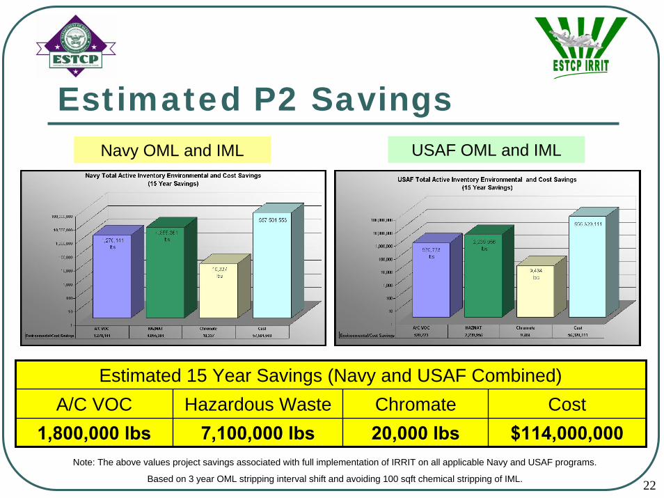
Estimated P2 SavingsNavy OML and IML USAF OML and IML
Estimated 15 Year Savings (Navy and USAF Combined)A/C VOC Hazardous Waste Chromate Cost
1,800,000 lbs 7,100,000 lbs 20,000 lbs $114,000,000Note: The above values project savings associated with full implementation of IRRIT on all applicable Navy and USAF programs.
Based on 3 year OML stripping interval shift and avoiding 100 sqft chemical stripping of IML.

23
Conclusions and SummaryThe IRRIT was validated as an enhanced corrosion inspection tool and consistently demonstrated greater accuracy than existing visual inspection techniques.Significant pollution prevention savings can be realized for programs that implement the IRRIT technology.
IRRIT inherently produces a data record to supplement engineering disposition. The inspection rate of the IRRIT was approximately half the rate of visual inspection. However, improved inspection rates are expected with new generation camera systems.

24
PublicationsStrategic Environmental Research & Development Program (SERDP). Final Report, “Non-Destructive Testing of Corrosion Under Coatings”,Project Number 1137, Dated 1 September 2004.United States Patent 7,164,146 - System for Detecting Structural Defects and Features utilizing Blackbody Self-IlluminationUnited States Patent 7,193,215 - System and Method for Imaging of Coated SubstratesUnited States Patent Application 20060289766 - Spectral Filter System for Infrared Imaging of Substrates Through CoatingsUnited States Patent Application – IRRIT Enhanced ImagingJ. Steve Cargill et al., “Nondestructive Testing for Corrosion under Paint” Materials Evaluation, monthly periodical of American Society for Nondestructive Testing, February 2005Briefing, NAVAIR AUAV Engineering Conference (May 2006)

25
Conclusions and Summary
Mr. John Weir
Technology DevelopmentIntegrated Systems Eastern RegionNorthrop Grumman CorporationBethpage, NY
Phone: 516-575-5422
QUESTIONS
Additional contributors to this project were: Mr. Brian Pollock (WP-AFB project manager), Mr. Matthew Campbell (CTCproject manager), Mr. John Benfer (NAVAIR Jacksonville, principal investigator), Mr. Steven Chu (NGC), Mr. Nils Fonneland(NGC), Mr. Dennis Leyble (NGC), Mr. Mike Miller (CTC), Mr. David Allen (ASM Management), and Mr. John Speers (WP-AFB).

26
Back-Up

27
IRRIT Examples

28
IRRIT Examples

29
IRRIT ExamplesIR Flash Primer Image
Visual Flash Primer Image
IR Painted Image IR Stripped Image
Visual Painted Image Visual Stripped Image

30
IRRIT Examples
31
IRRIT Examples
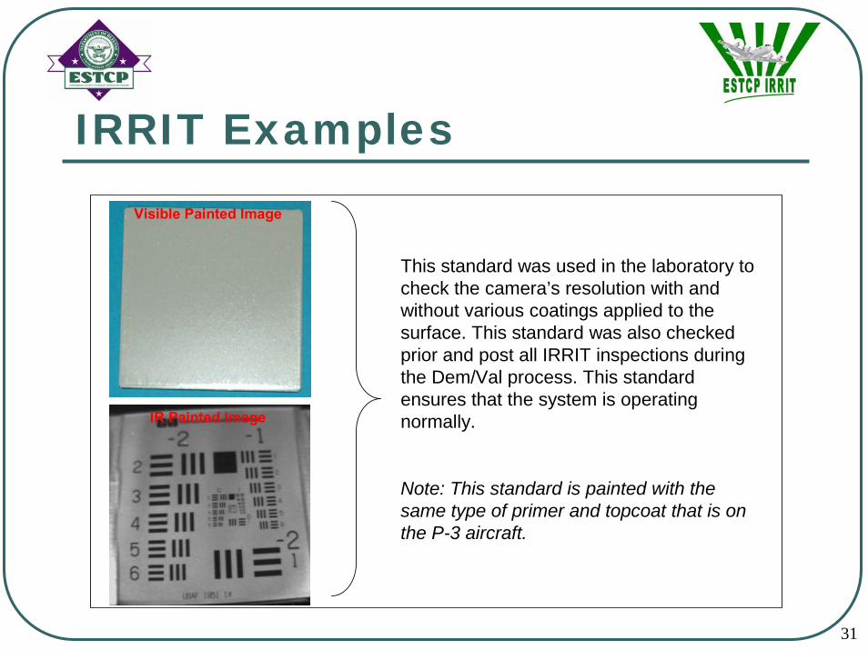
This standard was used in the laboratory to check the camera’s resolution with and without various coatings applied to the surface. This standard was also checked prior and post all IRRIT inspections during the Dem/Val process. This standard ensures that the system is operating normally.
Note: This standard is painted with the same type of primer and topcoat that is on the P-3 aircraft.
Visible Painted Image
IR Painted Image

32
Results – Weighted Average
12%
82%
0%
10%
20%
30%
40%
50%
60%
70%
80%
90%
Ave
rage
Acc
urac
y
Average Accuracy 12% 82%
Visual Inspection Results IRRIT Inspection Results
Average Accuracy: IRRIT Inspection versus Visual Inspection
33
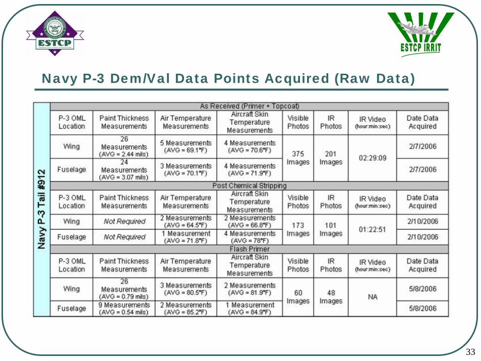
Navy P-3 Dem/Val Data Points Acquired (Raw Data)

34
Navy P-3 Dem/Val Data Points Acquired (Raw Data)

35
Navy P-3 OML Real-Time Results vs Post-Processing Results

36
Navy P-3 OML Real-Time Results vs Post-Processing Results

37
Navy P-3 Dem/Val IRRIT Scan Rates

38
USAF KC-135 Dem/Val Data Points Acquired (Raw Data)

39
USAF B-52 Dem/Val Data Points Acquired (Raw Data)

40
USAF KC-135 IML Real-Time Results vs Post-Processing Results

41
USAF B-52 IML Real-Time Results vs Post-Processing Results

42
USAF KC-135 and B-52 Dem/Val IRRIT Scan Rates

43
IRRIT Examples

44
IRRIT Examples
3.75-5 μm: OPTIMIZED FILTER3-5 μm: STANDARD FILTER
Optimized Filter Results
**Received new Merlin IR camera with internal 3.75-5 micron filter.


