INFRARED RADIANT TUBE HEATER - spaceray.com GENERAL INFORMATION This heater is a self-contained...
22
Submittal ♦ CB May10 CB 20–50 SERIES NATURAL GAS 5-SINGLE STAGE (CHECK ONE) (CHECK ONE) (CHECK ONE) CB 40–50 SERIES PROPANE GAS 7-TWO STAGE NAME: DATE: PROJECT: ADDRESS: NAME: ARCHITECT/ENGINEER: ADDRESS: NAME: CONTRACTOR: ADDRESS: SUBMITTED BY: EQUIPMENT USED : ACCESSORIES : Chain Mounting Kit Vent Cap Thermostat Combustion Air Cap Gas Pressure Regulator 90º Elbow Gas Shut-Off Valve Other Side Reflector Other Corner Reflector Other INFRARED RADIANT TUBE HEATER
Transcript of INFRARED RADIANT TUBE HEATER - spaceray.com GENERAL INFORMATION This heater is a self-contained...
Submittal ♦ CB May10
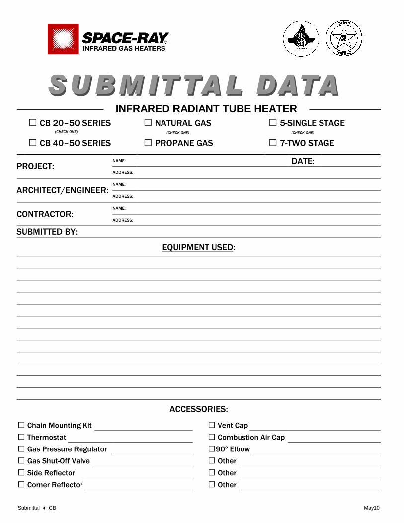
CB 20–50 SERIES NATURAL GAS 5-SINGLE STAGE(CHECK ONE) (CHECK ONE) (CHECK ONE)
CB 40–50 SERIES PROPANE GAS 7-TWO STAGE
NAME: DATE:PROJECT:
ADDRESS:
NAME:
ARCHITECT/ENGINEER:ADDRESS:
NAME:
CONTRACTOR:ADDRESS:
SUBMITTED BY:
EQUIPMENT USED:
ACCESSORIES:
Chain Mounting Kit Vent Cap
Thermostat Combustion Air Cap
Gas Pressure Regulator 90º Elbow
Gas Shut-Off Valve Other
Side Reflector Other
Corner Reflector Other
INFRARED RADIANT TUBE HEATER
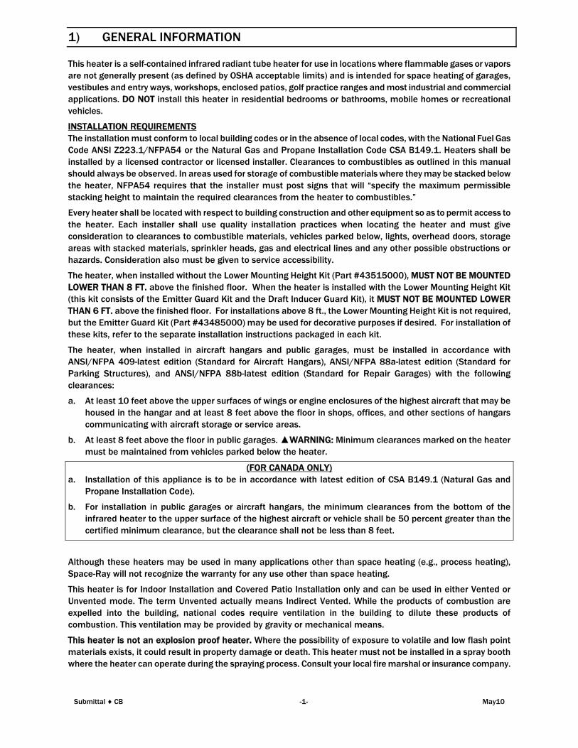
1) GENERAL INFORMATION
This heater is a self-contained infrared radiant tube heater for use in locations where flammable gases or vapors
are not generally present (as defined by OSHA acceptable limits) and is intended for space heating of garages,
vestibules and entry ways, workshops, enclosed patios, golf practice ranges and most industrial and commercial
applications. DO NOT install this heater in residential bedrooms or bathrooms, mobile homes or recreational
vehicles.
INSTALLATION REQUIREMENTS
The installation must conform to local building codes or in the absence of local codes, with the National Fuel Gas
Code ANSI Z223.1/NFPA54 or the Natural Gas and Propane Installation Code CSA B149.1. Heaters shall be
installed by a licensed contractor or licensed installer. Clearances to combustibles as outlined in this manual
should always be observed. In areas used for storage of combustible materials where they may be stacked below
the heater, NFPA54 requires that the installer must post signs that will “specify the maximum permissible
stacking height to maintain the required clearances from the heater to combustibles.”
Every heater shall be located with respect to building construction and other equipment so as to permit access to
the heater. Each installer shall use quality installation practices when locating the heater and must give
consideration to clearances to combustible materials, vehicles parked below, lights, overhead doors, storage
areas with stacked materials, sprinkler heads, gas and electrical lines and any other possible obstructions or
hazards. Consideration also must be given to service accessibility.
The heater, when installed without the Lower Mounting Height Kit (Part #43515000), MUST NOT BE MOUNTED
LOWER THAN 8 FT. above the finished floor. When the heater is installed with the Lower Mounting Height Kit
(this kit consists of the Emitter Guard Kit and the Draft Inducer Guard Kit), it MUST NOT BE MOUNTED LOWER
THAN 6 FT. above the finished floor. For installations above 8 ft., the Lower Mounting Height Kit is not required,
but the Emitter Guard Kit (Part #43485000) may be used for decorative purposes if desired. For installation of
these kits, refer to the separate installation instructions packaged in each kit.
The heater, when installed in aircraft hangars and public garages, must be installed in accordance with
ANSI/NFPA 409-latest edition (Standard for Aircraft Hangars), ANSI/NFPA 88a-latest edition (Standard for
Parking Structures), and ANSI/NFPA 88b-latest edition (Standard for Repair Garages) with the following
clearances:
a. At least 10 feet above the upper surfaces of wings or engine enclosures of the highest aircraft that may be
housed in the hangar and at least 8 feet above the floor in shops, offices, and other sections of hangars
communicating with aircraft storage or service areas.
b. At least 8 feet above the floor in public garages. ▲WARNING: Minimum clearances marked on the heater
must be maintained from vehicles parked below the heater.
(FOR CANADA ONLY)
a. Installation of this appliance is to be in accordance with latest edition of CSA B149.1 (Natural Gas and
Propane Installation Code).
b. For installation in public garages or aircraft hangars, the minimum clearances from the bottom of the
infrared heater to the upper surface of the highest aircraft or vehicle shall be 50 percent greater than the
certified minimum clearance, but the clearance shall not be less than 8 feet.
Although these heaters may be used in many applications other than space heating (e.g., process heating),
Space-Ray will not recognize the warranty for any use other than space heating.
This heater is for Indoor Installation and Covered Patio Installation only and can be used in either Vented or
Unvented mode. The term Unvented actually means Indirect Vented. While the products of combustion are
expelled into the building, national codes require ventilation in the building to dilute these products of
combustion. This ventilation may be provided by gravity or mechanical means.
This heater is not an explosion proof heater. Where the possibility of exposure to volatile and low flash point
materials exists, it could result in property damage or death. This heater must not be installed in a spray booth
where the heater can operate during the spraying process. Consult your local fire marshal or insurance company.
Submittal ♦ CB -1- May10
High Altitude:
Appliances are supplied as standard for altitudes of O to 2,000 feet (0-610 m). High-altitude ratings are obtained
by a change in the orifice size. When ordered for high altitude installations, burners are supplied by the factory
ready for high altitude installation. Check the nameplate for altitude before proceeding with the installation. In
Canada the adjustment for altitude is made in accordance with Standard CGA 2.17, Gas-Fired Appliances for Use
at High Altitudes.
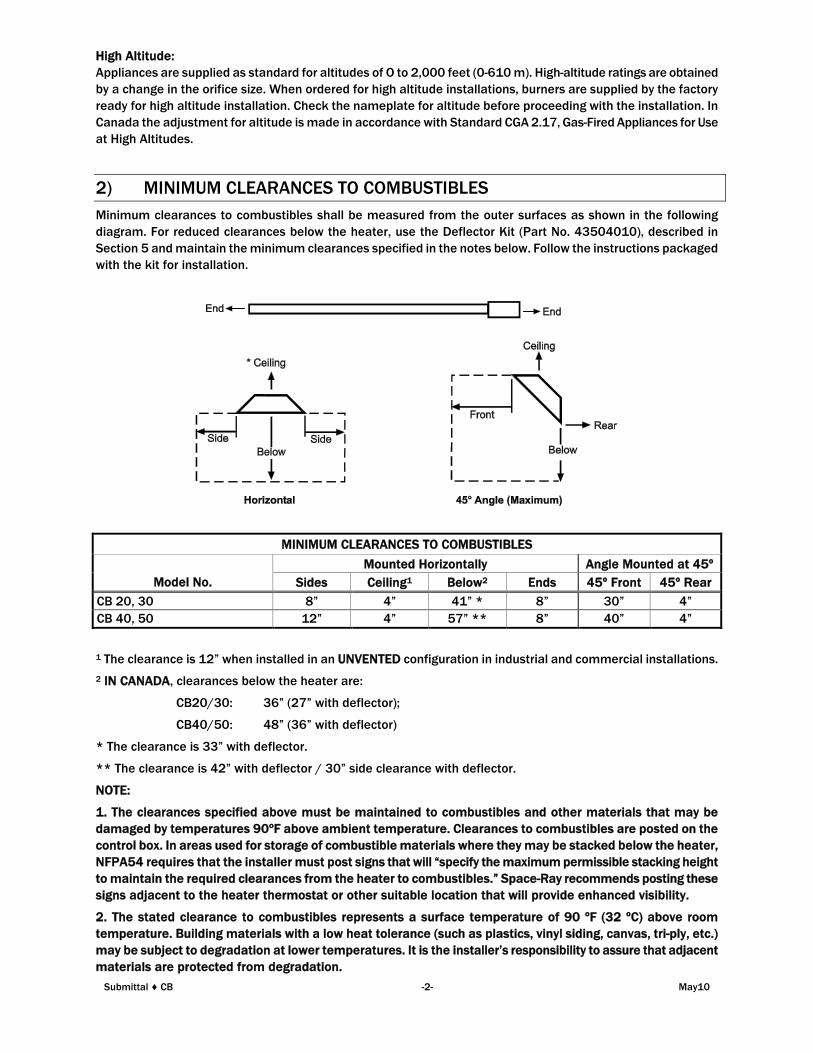
2) MINIMUM CLEARANCES TO COMBUSTIBLES
Minimum clearances to combustibles shall be measured from the outer surfaces as shown in the following
diagram. For reduced clearances below the heater, use the Deflector Kit (Part No. 43504010), described in
Section 5 and maintain the minimum clearances specified in the notes below. Follow the instructions packaged
with the kit for installation.
MINIMUM CLEARANCES TO COMBUSTIBLES
Mounted Horizontally Angle Mounted at 45º
Model No. Sides Ceiling1 Below2 Ends 45º Front 45º Rear
CB 20, 30 8” 4” 41” * 8” 30” 4”
CB 40, 50 12” 4” 57” ** 8” 40” 4”
1 The clearance is 12” when installed in an UNVENTED configuration in industrial and commercial installations.
2 IN CANADA, clearances below the heater are:
CB20/30: 36” (27” with deflector);
CB40/50: 48” (36” with deflector)
* The clearance is 33” with deflector.
** The clearance is 42” with deflector / 30” side clearance with deflector.
NOTE:
1. The clearances specified above must be maintained to combustibles and other materials that may be
damaged by temperatures 90ºF above ambient temperature. Clearances to combustibles are posted on the
control box. In areas used for storage of combustible materials where they may be stacked below the heater,
NFPA54 requires that the installer must post signs that will “specify the maximum permissible stacking height
to maintain the required clearances from the heater to combustibles.” Space-Ray recommends posting these
signs adjacent to the heater thermostat or other suitable location that will provide enhanced visibility.
2. The stated clearance to combustibles represents a surface temperature of 90 ºF (32 ºC) above room
temperature. Building materials with a low heat tolerance (such as plastics, vinyl siding, canvas, tri-ply, etc.)
may be subject to degradation at lower temperatures. It is the installer’s responsibility to assure that adjacent
materials are protected from degradation.
Submittal ♦ CB -2- May10
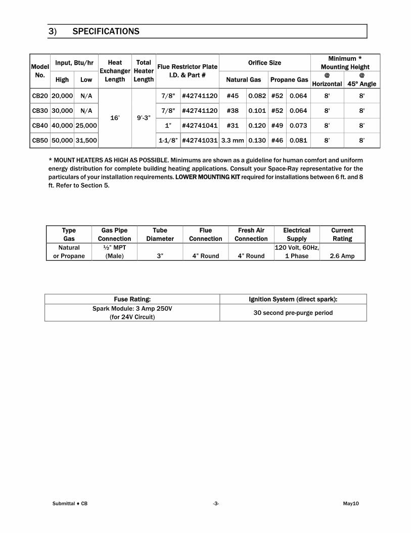
3) SPECIFICATIONS
Input, Btu/hr Orifice SizeMinimum *
Mounting HeightModel
No.High Low
Heat
Exchanger
Length
Total
Heater
Length
Flue Restrictor Plate
I.D. & Part #Natural Gas Propane Gas
@
Horizontal
@
45º Angle
CB20 20,000 N/A 7/8" #42741120 #45 O.082 #52 0.064 8' 8'
CB30 30,000 N/A 7/8" #42741120 #38 0.101 #52 0.064 8' 8'
CB40 40,000 25,000 1” #42741041 #31 0.120 #49 0.073 8’ 8’
CB50 50,000 31,500
16’ 9’-3”
1-1/8” #42741031 3.3 mm 0.130 #46 0.081 8’ 8’
* MOUNT HEATERS AS HIGH AS POSSIBLE. Minimums are shown as a guideline for human comfort and uniform
energy distribution for complete building heating applications. Consult your Space-Ray representative for the
particulars of your installation requirements. LOWER MOUNTING KIT required for installations between 6 ft. and 8
ft. Refer to Section 5.
Type
Gas
Gas Pipe
Connection
Tube
Diameter
Flue
Connection
Fresh Air
Connection
Electrical
Supply
Current
Rating
Natural
or Propane
½” MPT
(Male) 3” 4” Round 4” Round
120 Volt, 60Hz,
1 Phase 2.6 Amp
Fuse Rating: Ignition System (direct spark):
Spark Module: 3 Amp 250V
(for 24V Circuit)30 second pre-purge period
Submittal ♦ CB -3- May10

4) DIMENSIONS
Submittal ♦ CB -4- May10
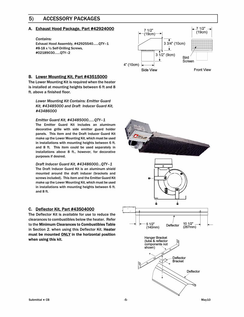
5) ACCESSORY PACKAGES
A. Exhaust Hood Package, Part #42924000
Contains:Exhaust Hood Assembly, #42925540……QTY–1
#8-18 x ½ Self-Drilling Screws,
#02189030……QTY–2
B. Lower Mounting Kit, Part #43515000The Lower Mounting Kit is required when the heater
is installed at mounting heights between 6 ft and 8
ft. above a finished floor.
Lower Mounting Kit Contains: Emitter Guard
Kit, #43485000 and Draft Inducer Guard Kit,
#43486000
Emitter Guard Kit, #43485000……QTY–1The Emitter Guard Kit includes an aluminum
decorative grille with side emitter guard holder
panels. This item and the Draft Inducer Guard Kit
make up the Lower Mounting Kit, which must be used
in installations with mounting heights between 6 ft.
and 8 ft. This item could be used separately in
installations above 8 ft., however, for decorative
purposes if desired.
Draft Inducer Guard Kit, #43486000…QTY–1The Draft Inducer Guard Kit is an aluminum shield
mounted around the draft inducer (brackets and
screws included). This item and the Emitter Guard Kit
make up the Lower Mounting Kit, which must be used
in installations with mounting heights between 6 ft.
and 8 ft.
C. Deflector Kit, Part #43504000The Deflector Kit is available for use to reduce the
clearances to combustibles below the heater. Refer
to the Minimum Clearances to Combustibles Table
in Section 2. when using this Deflector Kit. Heater
must be mounted ONLY in the horizontal position
when using this kit.
Submittal ♦ CB -5- May10
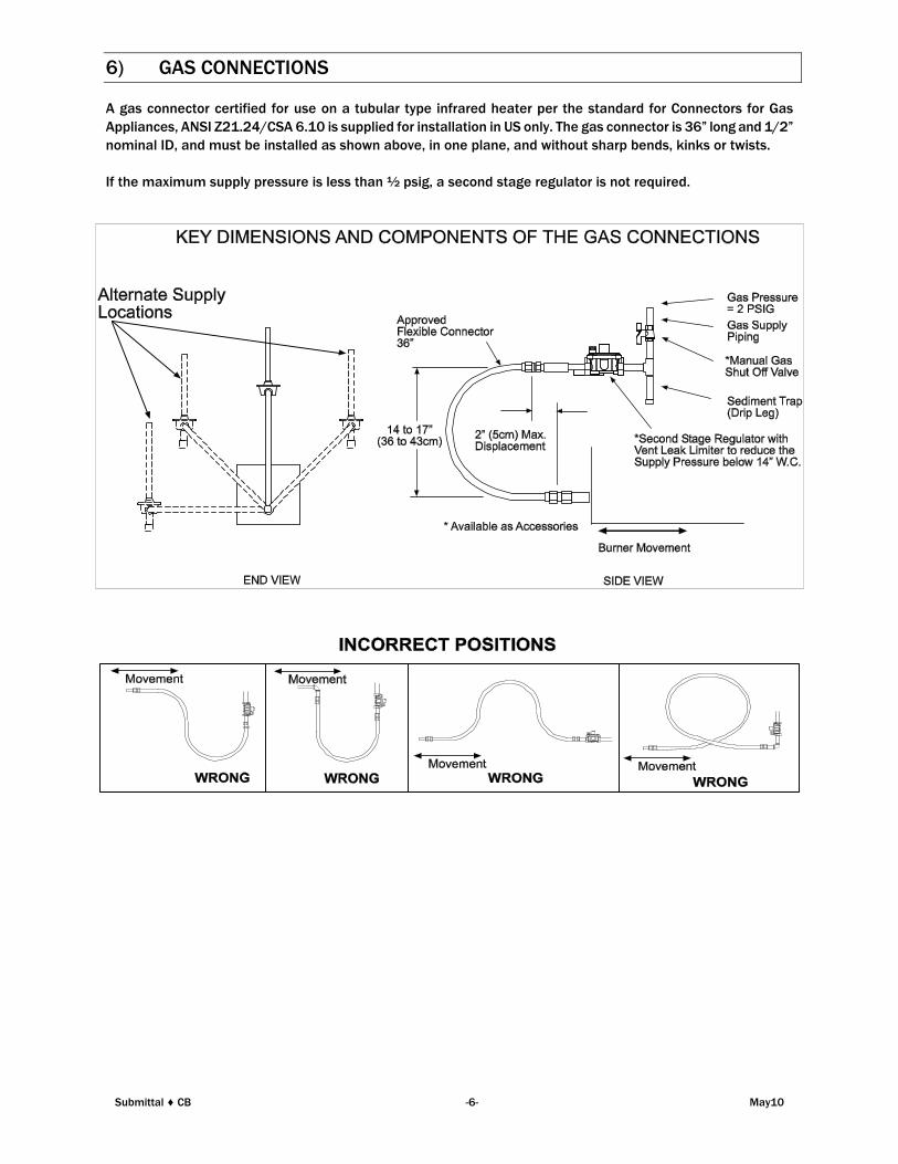
6) GAS CONNECTIONS
A gas connector certified for use on a tubular type infrared heater per the standard for Connectors for Gas
Appliances, ANSI Z21.24/CSA 6.10 is supplied for installation in US only. The gas connector is 36” long and 1/2”
nominal ID, and must be installed as shown above, in one plane, and without sharp bends, kinks or twists.
If the maximum supply pressure is less than ½ psig, a second stage regulator is not required.
Submittal ♦ CB -6- May10
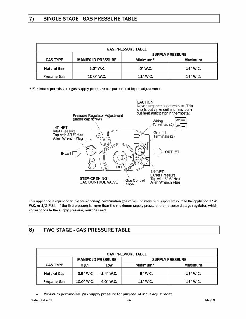
7) SINGLE STAGE - GAS PRESSURE TABLE
GAS PRESSURE TABLE
SUPPLY PRESSURE
GAS TYPE MANIFOLD PRESSURE Minimum* Maximum
Natural Gas 3.5” W.C. 5” W.C. 14” W.C.
Propane Gas 10.0” W.C. 11” W.C. 14” W.C.
* Minimum permissible gas supply pressure for purpose of input adjustment.
This appliance is equipped with a step-opening, combination gas valve. The maximum supply pressure to the appliance is 14”
W.C. or 1/2 P.S.I. If the line pressure is more than the maximum supply pressure, then a second stage regulator, which
corresponds to the supply pressure, must be used.
8) TWO STAGE - GAS PRESSURE TABLE
GAS PRESSURE TABLE
MANIFOLD PRESSURE SUPPLY PRESSURE
GAS TYPE High Low Minimum* Maximum
Natural Gas 3.5” W.C. 1.4” W.C. 5” W.C. 14” W.C.
Propane Gas 10.0” W.C. 4.0” W.C. 11” W.C. 14” W.C.
Minimum permissible gas supply pressure for purpose of input adjustment.
Submittal ♦ CB -7- May10
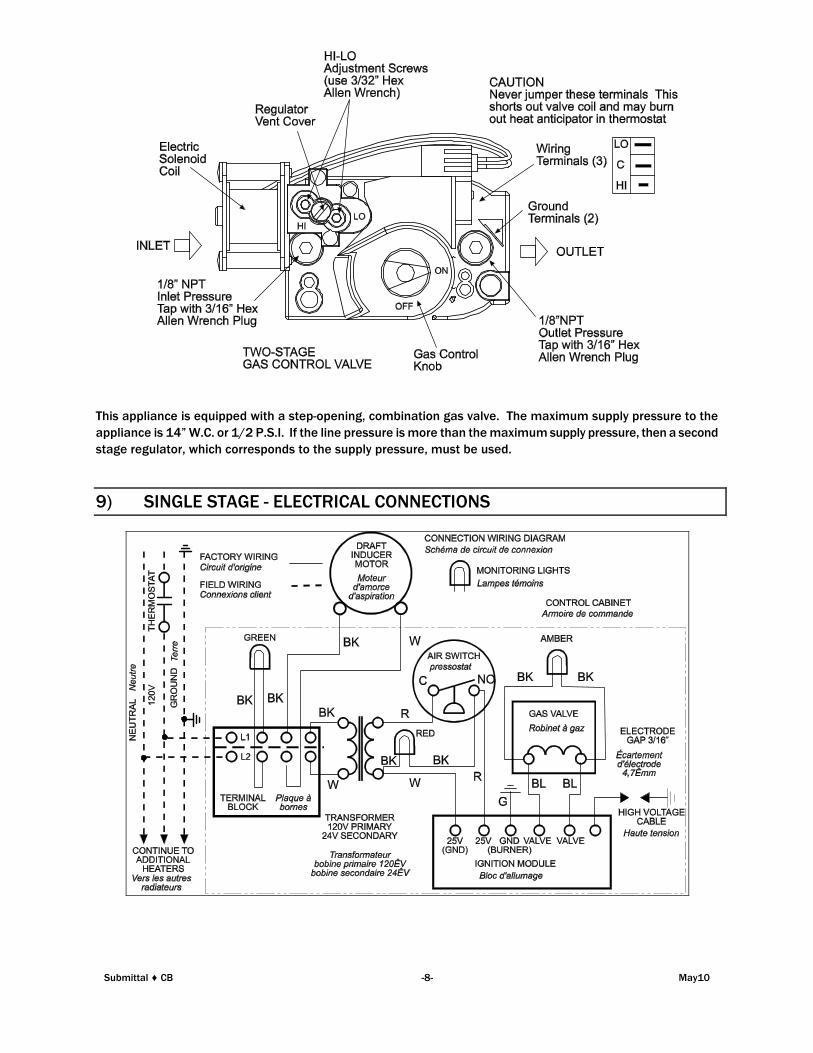
This appliance is equipped with a step-opening, combination gas valve. The maximum supply pressure to the
appliance is 14” W.C. or 1/2 P.S.I. If the line pressure is more than the maximum supply pressure, then a second
stage regulator, which corresponds to the supply pressure, must be used.
9) SINGLE STAGE - ELECTRICAL CONNECTIONS
Submittal ♦ CB -8- May10
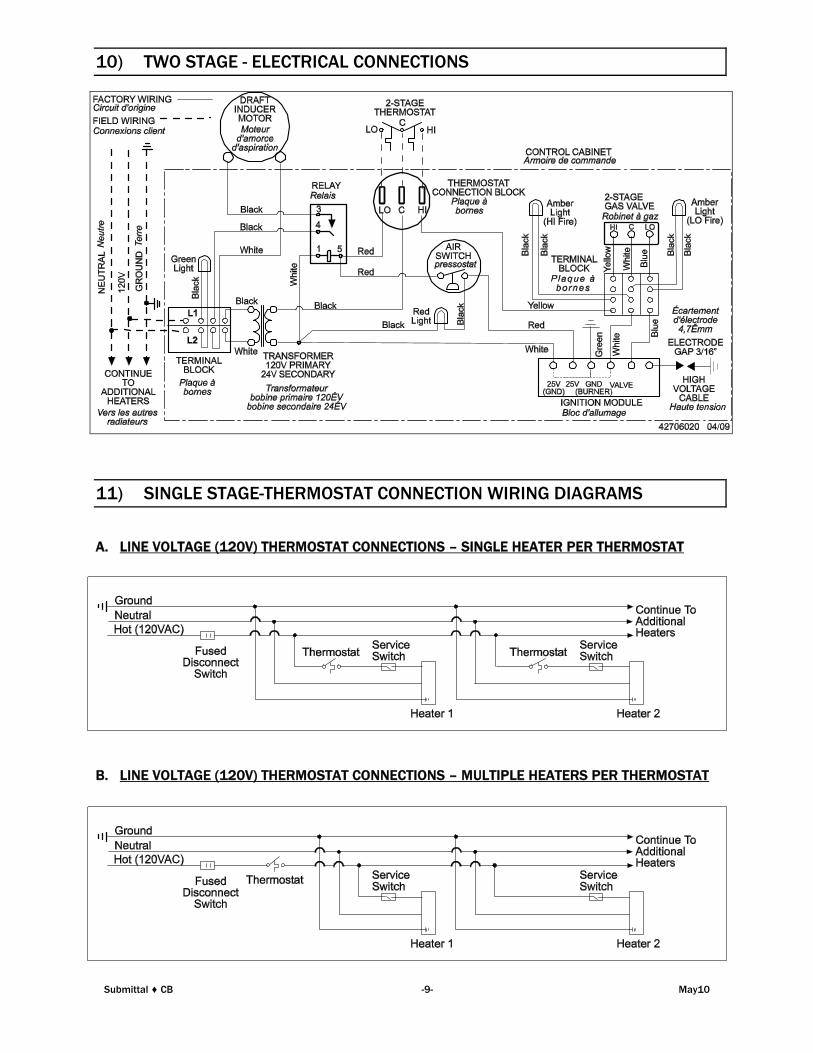
10) TWO STAGE - ELECTRICAL CONNECTIONS
11) SINGLE STAGE-THERMOSTAT CONNECTION WIRING DIAGRAMS
A. LINE VOLTAGE (120V) THERMOSTAT CONNECTIONS – SINGLE HEATER PER THERMOSTAT
B. LINE VOLTAGE (120V) THERMOSTAT CONNECTIONS – MULTIPLE HEATERS PER THERMOSTAT
Submittal ♦ CB -9- May10
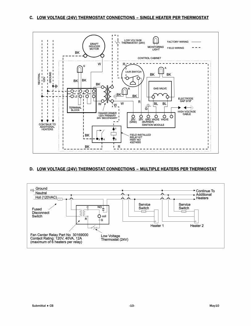
C. LOW VOLTAGE (24V) THERMOSTAT CONNECTIONS – SINGLE HEATER PER THERMOSTAT
D. LOW VOLTAGE (24V) THERMOSTAT CONNECTIONS – MULTIPLE HEATERS PER THERMOSTAT
Submittal ♦ CB -10- May10
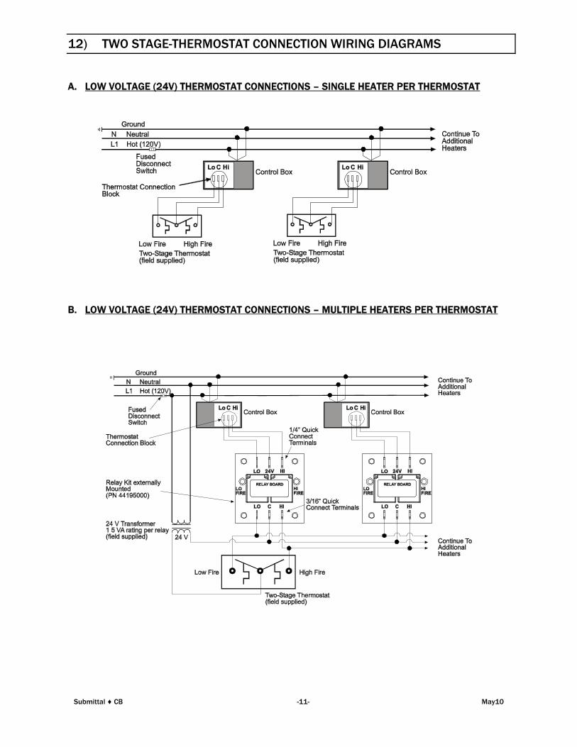
12) TWO STAGE-THERMOSTAT CONNECTION WIRING DIAGRAMS
A. LOW VOLTAGE (24V) THERMOSTAT CONNECTIONS – SINGLE HEATER PER THERMOSTAT
B. LOW VOLTAGE (24V) THERMOSTAT CONNECTIONS – MULTIPLE HEATERS PER THERMOSTAT
Submittal ♦ CB -11- May10
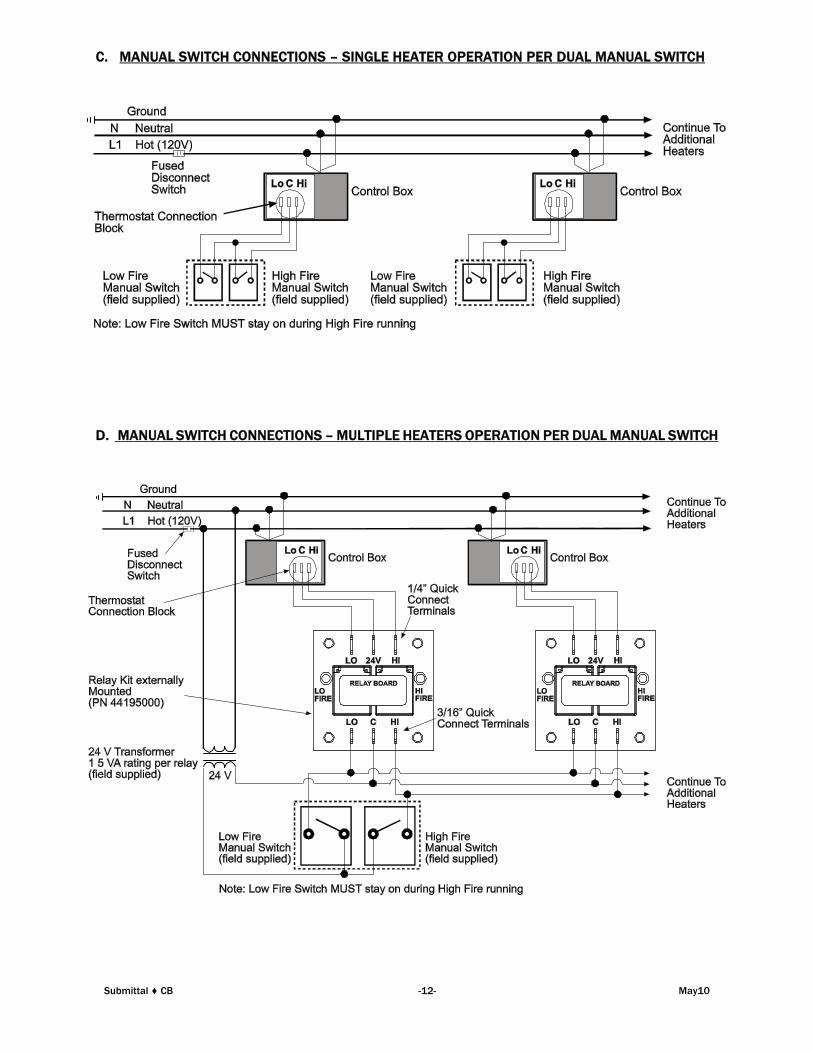
C. MANUAL SWITCH CONNECTIONS – SINGLE HEATER OPERATION PER DUAL MANUAL SWITCH
D. MANUAL SWITCH CONNECTIONS – MULTIPLE HEATERS OPERATION PER DUAL MANUAL SWITCH
Submittal ♦ CB -12- May10
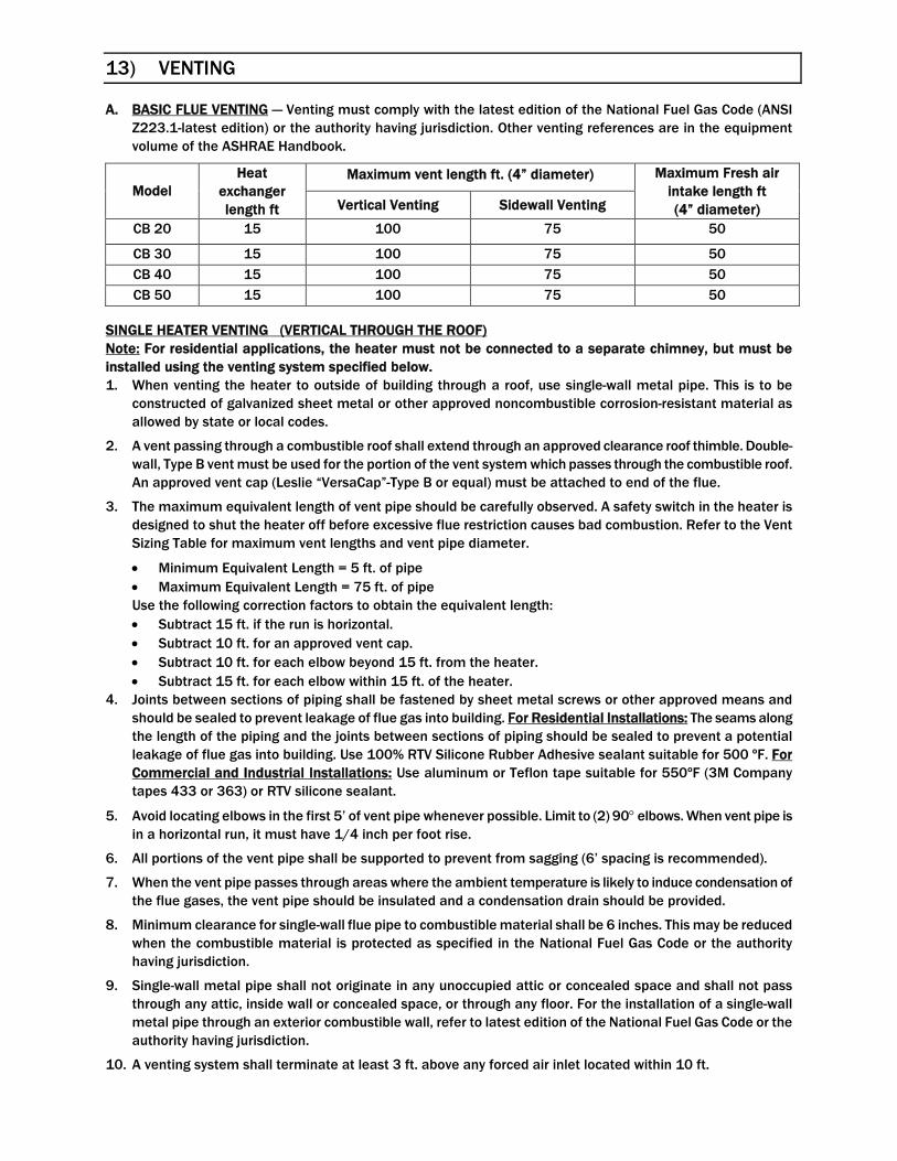
13) VENTING
A. BASIC FLUE VENTING — Venting must comply with the latest edition of the National Fuel Gas Code (ANSI
Z223.1-latest edition) or the authority having jurisdiction. Other venting references are in the equipment
volume of the ASHRAE Handbook.
SINGLE HEATER VENTING (VERTICAL THROUGH THE ROOF)
Note: For residential applications, the heater must not be connected to a separate chimney, but must be
installed using the venting system specified below.
1. When venting the heater to outside of building through a roof, use single-wall metal pipe. This is to be
constructed of galvanized sheet metal or other approved noncombustible corrosion-resistant material as
allowed by state or local codes.
2. A vent passing through a combustible roof shall extend through an approved clearance roof thimble. Double-
wall, Type B vent must be used for the portion of the vent system which passes through the combustible roof.
An approved vent cap (Leslie “VersaCap”-Type B or equal) must be attached to end of the flue.
3. The maximum equivalent length of vent pipe should be carefully observed. A safety switch in the heater is
designed to shut the heater off before excessive flue restriction causes bad combustion. Refer to the Vent
Sizing Table for maximum vent lengths and vent pipe diameter.
Minimum Equivalent Length = 5 ft. of pipe
Maximum Equivalent Length = 75 ft. of pipe
Use the following correction factors to obtain the equivalent length:
Subtract 15 ft. if the run is horizontal.
Subtract 10 ft. for an approved vent cap.
Subtract 10 ft. for each elbow beyond 15 ft. from the heater.
Subtract 15 ft. for each elbow within 15 ft. of the heater.
4. Joints between sections of piping shall be fastened by sheet metal screws or other approved means and
should be sealed to prevent leakage of flue gas into building. For Residential Installations: The seams along
the length of the piping and the joints between sections of piping should be sealed to prevent a potential
leakage of flue gas into building. Use 100% RTV Silicone Rubber Adhesive sealant suitable for 500 ºF. For
Commercial and Industrial Installations: Use aluminum or Teflon tape suitable for 550ºF (3M Company
tapes 433 or 363) or RTV silicone sealant.
5. Avoid locating elbows in the first 5’ of vent pipe whenever possible. Limit to (2) 90 elbows. When vent pipe is
in a horizontal run, it must have 1/4 inch per foot rise.
6. All portions of the vent pipe shall be supported to prevent from sagging (6’ spacing is recommended).
7. When the vent pipe passes through areas where the ambient temperature is likely to induce condensation of
the flue gases, the vent pipe should be insulated and a condensation drain should be provided.
8. Minimum clearance for single-wall flue pipe to combustible material shall be 6 inches. This may be reduced
when the combustible material is protected as specified in the National Fuel Gas Code or the authority
having jurisdiction.
9. Single-wall metal pipe shall not originate in any unoccupied attic or concealed space and shall not pass
through any attic, inside wall or concealed space, or through any floor. For the installation of a single-wall
metal pipe through an exterior combustible wall, refer to latest edition of the National Fuel Gas Code or the
authority having jurisdiction.
10. A venting system shall terminate at least 3 ft. above any forced air inlet located within 10 ft.
Maximum vent length ft. (4” diameter)Model
Heat
exchanger
length ft Vertical Venting Sidewall Venting
Maximum Fresh air
intake length ft
(4” diameter)
CB 20 15 100 75 50
CB 30 15 100 75 50
CB 40 15 100 75 50
CB 50 15 100 75 50
Submittal ♦ CB -13- May10
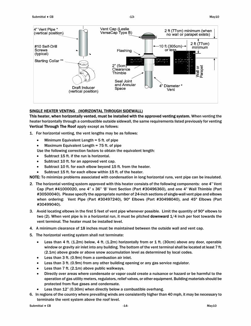
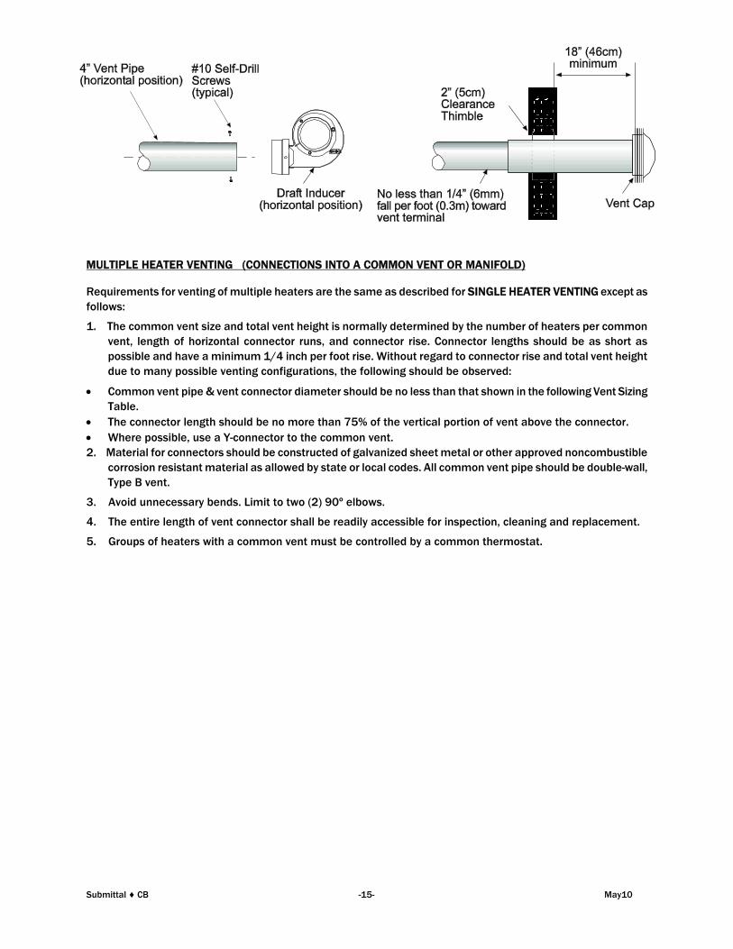
SINGLE HEATER VENTING (HORIZONTAL THROUGH SIDEWALL)
This heater, when horizontally vented, must be installed with the approved venting system. When venting the
heater horizontally through a combustible outside sidewall, the same requirements listed previously for venting
Vertical Through The Roof apply except as follows:
1. For horizontal venting, the vent lengths may be as follows:
Minimum Equivalent Length = 5 ft. of pipe
Maximum Equivalent Length = 75 ft. of pipe
Use the following correction factors to obtain the equivalent length:
Subtract 15 ft. if the run is horizontal.
Subtract 10 ft. for an approved vent cap.
Subtract 10 ft. for each elbow beyond 15 ft. from the heater.
Subtract 15 ft. for each elbow within 15 ft. of the heater.
NOTE: To minimize problems associated with condensation in long horizontal runs, vent pipe can be insulated.
2. The horizontal venting system approved with this heater consists of the following components: one 4” Vent
Cap (Part #41000020, one 4” x 36” ‘B’ Vent Section (Part #30496360), and one 4” Wall Thimble (Part
#30500040). Please specify the appropriate number of 24-inch sections of single-wall vent pipe and elbows
when ordering: Vent Pipe (Part #30497240), 90º Elbows (Part #30498040), and 45º Elbows (Part
#30499040).
3. Avoid locating elbows in the first 5 feet of vent pipe whenever possible. Limit the quantity of 90º elbows to
two (2). When vent pipe is in a horizontal run, it must be pitched downward 1/4 inch per foot towards the
vent terminal. The heater must be installed level.
4. A minimum clearance of 18 inches must be maintained between the outside wall and vent cap.
5. The horizontal venting system shall not terminate:
Less than 4 ft. (1.2m) below, 4 ft. (1.2m) horizontally from or 1 ft. (30cm) above any door, operable
window or gravity air inlet into any building. The bottom of the vent terminal shall be located at least 7 ft.
(2.1m) above grade or above snow accumulation level as determined by local codes.
Less than 3 ft. (0.9m) from a combustion air inlet.
Less than 3 ft. (0.9m) from any other building opening or any gas service regulator.
Less than 7 ft. (2.1m) above public walkways.
Directly over areas where condensate or vapor could create a nuisance or hazard or be harmful to the
operation of gas utility meters, regulators, relief valves, or other equipment. Building materials should be
protected from flue gases and condensate.
Less than 12” (0.30m) when directly below a combustible overhang.
6. In regions of the country where prevailing winds are consistently higher than 40 mph, it may be necessary to
terminate the vent system above the roof level.
Submittal ♦ CB -14- May10
MULTIPLE HEATER VENTING (CONNECTIONS INTO A COMMON VENT OR MANIFOLD)
Requirements for venting of multiple heaters are the same as described for SINGLE HEATER VENTING except as
follows:
1. The common vent size and total vent height is normally determined by the number of heaters per common
vent, length of horizontal connector runs, and connector rise. Connector lengths should be as short as
possible and have a minimum 1/4 inch per foot rise. Without regard to connector rise and total vent height
due to many possible venting configurations, the following should be observed:
Common vent pipe & vent connector diameter should be no less than that shown in the following Vent Sizing
Table.
The connector length should be no more than 75% of the vertical portion of vent above the connector.
Where possible, use a Y-connector to the common vent.
2. Material for connectors should be constructed of galvanized sheet metal or other approved noncombustible
corrosion resistant material as allowed by state or local codes. All common vent pipe should be double-wall,
Type B vent.
3. Avoid unnecessary bends. Limit to two (2) 90º elbows.
4. The entire length of vent connector shall be readily accessible for inspection, cleaning and replacement.
5. Groups of heaters with a common vent must be controlled by a common thermostat.
Submittal ♦ CB -15- May10
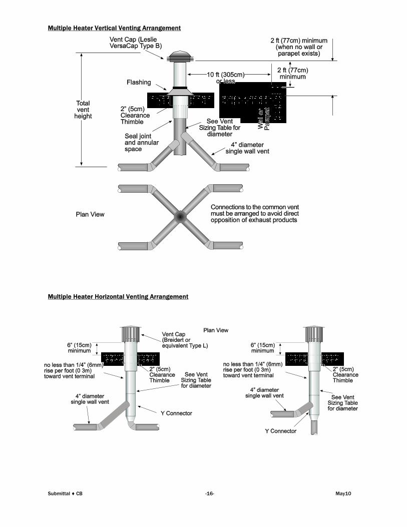
Multiple Heater Vertical Venting Arrangement
Multiple Heater Horizontal Venting Arrangement
Submittal ♦ CB -16- May10
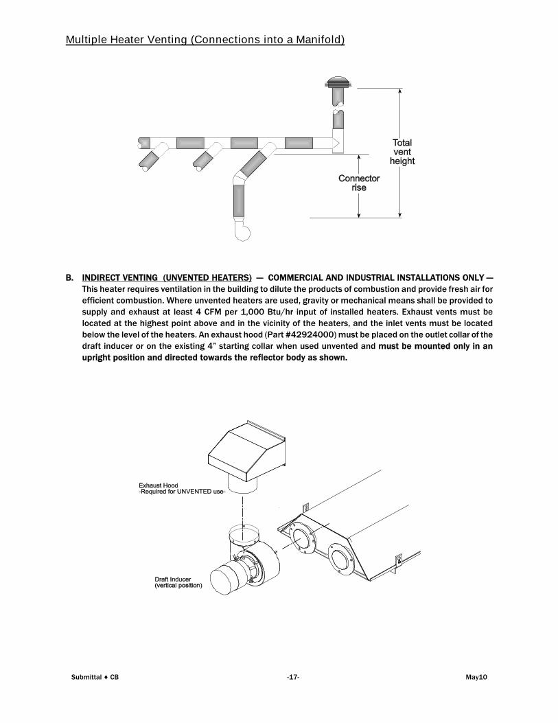
Multiple Heater Venting (Connections into a Manifold)
B. INDIRECT VENTING (UNVENTED HEATERS) — COMMERCIAL AND INDUSTRIAL INSTALLATIONS ONLY —
This heater requires ventilation in the building to dilute the products of combustion and provide fresh air for
efficient combustion. Where unvented heaters are used, gravity or mechanical means shall be provided to
supply and exhaust at least 4 CFM per 1,000 Btu/hr input of installed heaters. Exhaust vents must be
located at the highest point above and in the vicinity of the heaters, and the inlet vents must be located
below the level of the heaters. An exhaust hood (Part #42924000) must be placed on the outlet collar of the
draft inducer or on the existing 4” starting collar when used unvented and must be mounted only in an
upright position and directed towards the reflector body as shown.
Submittal ♦ CB -17- May10
14) AIR FOR COMBUSTION
If indoor combustion air is to be supplied for a tightly enclosed area, one square inch of free area opening shall
be provided below the heater for each 1,000 Btu/hr of heater input. Adequate clearances around the perforated
fresh air plate must be maintained at all times. In larger open areas of buildings, infiltration normally is adequate
to provide air for combustion.
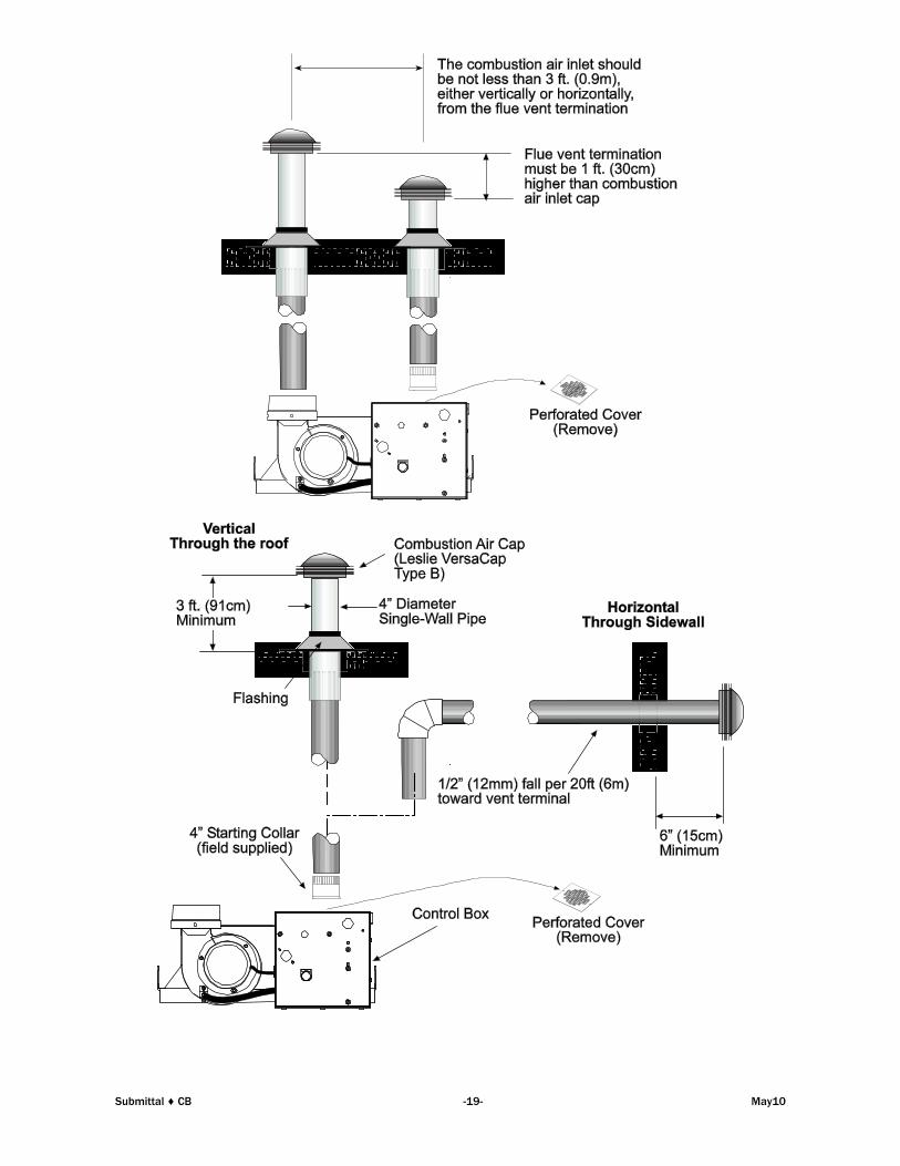
15) DIRECT OUTSIDE AIR FOR COMBUSTION
Outside combustion air should be supplied directly to the heater when the building is subject to negative
pressure, or when contaminants or high humidity are present in the building air. These contaminants include
paints, solvents, corrosive vapors or any other foreign particles that may cause damage to the heater or result in
poor combustion.
Outside combustion air can be brought directly to the heater by a 4” diameter duct less than 50 ft. long or
equivalent (see table in Section 13) based on selected model and heat exchanger lengths). This is attached to the
4” diameter starting collar. The starting collar is fitted to the top of the control box cabinet after first removing
and discarding the perforated cover. An approved vent cap must be placed directly on the end of the outside
combustion air inlet pipe. The combustion air inlet should be not less than 3 ft. (0.9m), either vertically or
horizontally, from the flue vent termination. The air intake terminal must be located not less than 1 ft. (30cm)
above grade. It is good installation practice to supply combustion air from the same pressure zone as the vent
outlet. Avoid bringing combustion air to the heater from an attic space. There is no guarantee that adequate
combustion air will be supplied.
In colder climates, where necessary, insulate the outside combustion air duct. Avoid locating the outside
combustion air duct directly above the control box. Provide a capped cleanout T as necessary. In high humidity
applications, the control box should be sealed with silicone sealer.
In multiple heater applications, the combustion air intake may be ducted individually or common ducted in the
same configuration as shown for venting in Section 13. For combustion air intake duct sizing, please refer to the
Vent Sizing Table and use the diameter indicated, based on the number of heaters per duct.
Submittal ♦ CB -18- May10
Submittal ♦ CB -19- May10

16) SINGLE STAGE - SEQUENCE OF OPERATION
If the flame is not sensed during sequence T3 then the burner will automatically begin ignition sequence T2. If the
flame is not re-established the heater will go to lockout.
17) TWO STAGE - SEQUENCE OF OPERATION
If the flame is not sensed during sequence T3 or T4, then the burner will automatically begin ignition as in
sequence T2. If the flame is not re-established the heater will go to lockout.
Submittal ♦ CB -20- May10
18) LIMITED WARRANTY
LIMITED WARRANTY: Gas-Fired Products, Inc., the manufacturer, warrants to the original owner of any Space-Ray infrared
gas heater that said heater will be free from defects in material or workmanship under normal use and service. The heater(s)
shall be installed, used and maintained strictly in accordance with the manufacturer's instructions. The manufacturer's sole
obligation under this warranty shall be limited to furnishing replacement parts, F.O.B. Charlotte, NC, for 12 months from the
date of installation, or 18 months from the date of shipment by the manufacturer, whichever period shall expire first. Labor
charges for removal of defective parts and the installation of the replacement parts are not included. This warranty applies
only within the USA and Canada.
WARNING: Manufacturer's warranty shall not apply: (a) to damage to the heater when used in an atmosphere containing
halogenated hydrocarbons or other corrosive chemicals. Some compounds in the air can be ingested into the equipment and
can cause an accelerated rate of corrosion of some of the parts of the heating components. The use of such chemical
compounds in or near the operating environment of the heater should be avoided where a longer heater life is desirable; (b)
to any heater or components which have been repaired or replaced with other than factory parts, modified in any way,
misused or damaged, or which have been used contrary to the manufacturer's written instructions. Replacement parts are
available through Space-Ray representatives or their distributors.
LIMITATION OF WARRANTY: THERE ARE NO WARRANTIES, EXPRESS OR IMPLIED, WHICH EXTEND BEYOND THE DESCRIPTION
ON THE FACE HEREOF. WITHOUT LIMITING THE FOREGOING, THE MANUFACTURER EXPRESSLY EXCLUDES ANY AND ALL
IMPLIED WARRANTIES, INCLUDING BUT NOT LIMITED TO ANY IMPLIED WARRANTY OF FITNESS FOR A PARTICULAR PURPOSE
AND ANY IMPLIED WARRANTY OF MERCHANTABILITY FOR ITS PRODUCTS.
If any provision of this warranty is found to be void, unenforceable or unconscionable, then the same is hereby severed and
the remainder of this warranty is hereby saved and shall remain in force.
EXCLUSIVE REMEDY: The sole and exclusive remedy under this warranty is the replacement of the defective parts or heaters
as hereinabove specified. THE MANUFACTURER DOES HEREBY EXPRESSLY EXCLUDE ANY AND ALL LIABILITY FOR
INCIDENTAL AND CONSEQUENTIAL DAMAGES UNDER THIS OR ANY OTHER WARRANTY. Without intending to limit the
aforesaid exclusion, THE MANUFACTURER DOES HEREBY EXCLUDE ANY LIABILITY UNDER THIS OR ANY OTHER WARRANTY
FOR INJURIES AND COMMERCIAL LOSSES TO PROPERTY THAT RESULT FROM THE OPERATION, PROPER OR IMPROPER, OF
ITS PRODUCTS.
ADDITIONAL WARRANTY ON HEAT EMITTING SURFACE AND BURNER: Manufacturer warrants to the original owner of any CSA
design certified heater that, if installed, used and maintained strictly in accordance with the printed instructions received with
the heater, the manufacturer will at any time during the below listed time periods, furnish at no cost to the original owner,
replacement emitters or burners which have become inoperative by reason of any defect in our workmanship, materials or
construction. The manufacturer's obligation under this warranty shall be limited to furnishing replacements under the
following time periods from the date of installation:
Emitter Burner
CB Series: 5 Years 10 Years
The manufacturer will not be responsible for labor charges incurred for removal or installation of emitters. Any transportation
charges involved in the return or repair are excluded.
ADDITIONAL TERMS: Manufacturer assumes no liability for delay in performing its obligations under the aforesaid warranty.
Manufacturer assumes no liability for failure in performing its obligations thereunder if failure results directly or indirectly from
any cause beyond its control, including but not limited to acts of God, acts of Government, floods, fires, shortages of materials,
strikes and other labor difficulties or delays or failures of transportation facilities.
This is a Non-Residential product (excluding the CB Series which is certified for residential and non-residential use).
Installation and service shall be by a Licensed Contractor and in accordance with National and Local Codes.
When presenting warranty claims, proof of date of purchase must be submitted.
No Representative is authorized to assume for the manufacturer any liability except as set forth above.
SPACE-RAY®
A Division of Gas-Fired Products, Inc.
Post Office Box 36485 (28236) 305 Doggett Street (28203) Charlotte, North Carolina
Phone (704) 372-3485 Fax (704) 332-5843 www.spaceray.com email: [email protected]
Submittal ♦ CB -21- May10