
INFORMATION Micro Clamp...
8
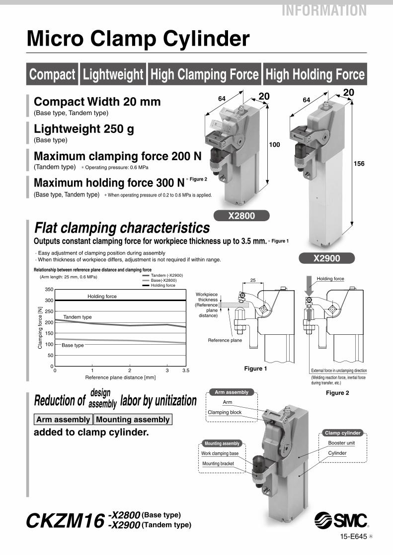
0 50 100 150 200 250 300 350 Reference plane distance [mm] Clamping force [N] Tandem (-X2900) Base(-X2800) Holding force Holding force Tandem type Base type (Arm length: 25 mm, 0.6 MPa) Relationship between reference plane distance and clamping force 0 1 2 3 3.5 25 Reference plane Workpiece thickness (Reference plane distance) Holding force External force in unclamping direction (Welding reaction force, inertial force during transfer, etc.) 20 Arm Work clamping base Booster unit Clamping block Mounting bracket Cylinder 64 156 X2800 X2900 Arm assembly Mounting assembly Clamp cylinder 20 64 100 Micro Clamp Cylinder Compact Lightweight High Clamping Force High Holding Force Compact Width 20 mm (Base type, Tandem type) Lightweight 250 g (Base type) Maximum clamping force 200 N (Tandem type) * Operating pressure: 0.6 MPa Maximum holding force 300 N * Figure 2 (Base type, Tandem type) * When operating pressure of 0.2 to 0.6 MPa is applied. Outputs constant clamping force for workpiece thickness up to 3.5 mm. * Figure 1 · Easy adjustment of clamping position during assembly · When thickness of workpiece differs, adjustment is not required if within range. Arm assembly Mounting assembly added to clamp cylinder. Flat clamping characteristics Reduction of labor by unitization design assembly Figure 1 Figure 2 INFORMATION CKZM16 15-E645 -X2800 (Base type) -X2900 (Tandem type) A
Transcript of INFORMATION Micro Clamp...
0
50
100
150
200
250
300
350
Reference plane distance [mm]
Cla
mpi
ng fo
rce
[N]
Tandem (-X2900)Base(-X2800)Holding force
Holding force
Tandem type
Base type
(Arm length: 25 mm, 0.6 MPa)
Relationship between reference plane distance and clamping force
0 1 2 3 3.5
25
Reference plane
Workpiecethickness
(Referenceplane
distance)
Holding force
External force in unclamping direction
(Welding reaction force, inertial forceduring transfer, etc.)
20
Arm
Work clamping base
Booster unit
Clamping block
Mounting bracket
Cylinder
64
156
X2800
X2900
Arm assembly
Mounting assembly
Clamp cylinder
2064
100
Micro Clamp Cylinder
Compact Lightweight High Clamping Force High Holding Force
Compact Width 20 mm(Base type, Tandem type)
Lightweight 250 g(Base type)
Maximum clamping force 200 N(Tandem type) * Operating pressure: 0.6 MPa
Maximum holding force 300 N * Figure 2
(Base type, Tandem type) * When operating pressure of 0.2 to 0.6 MPa is applied.
Outputs constant clamping force for workpiece thickness up to 3.5 mm. * Figure 1
· Easy adjustment of clamping position during assembly · When thickness of workpiece differs, adjustment is not required if within range.
Arm assembly Mounting assembly
added to clamp cylinder.
Flat clamping characteristics
Reduction of labor by unitizationdesign
assembly
Figure 1
Figure 2
INFORMATION
CKZM1615-E645
-X2800 (Base type)
-X2900 (Tandem type)A
Application examples
20
21
20
21
20
21
20
CKZM16 -X2800 -X2900
A
Keyway
Clamping base
Fits on key
Support bolt(Provided by customer)* Use as required.
Mounting bracket(Provided by customer)
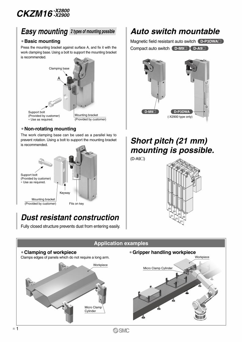
Easy mounting ¡Basic mountingPress the mounting bracket against surface A, and fix it with the work clamping base. Using a bolt to support the mounting bracket is recommended.
¡Non-rotating mountingThe work clamping base can be used as a parallel key to prevent rotation. Using a bolt to support the mounting bracket is recommended.
¡Clamping of workpieceClamps edges of panels which do not require a long arm.
¡Gripper handling workpiece
Micro ClampCylinder
WorkpieceMicro Clamp Cylinder
Workpiece
Short pitch (21 mm)mounting is possible.
Auto switch mountableD-P3DWA
D-M9 D-A9
Magnetic field resistant auto switch
Dust resistant constructionFully closed structure prevents dust from entering easily.
Compact auto switch
D-M9 D-P3DWA(-X2900 type only)
2 types of mounting possible
Mounting bracket(Provided by customer)
(D-A9)
Support bolt(Provided by customer)* Use as required.
1A

M9BW X2800CKZM16 68
Auto switch typeNil Without auto switch
* For applicable auto switch models, refer to the below table.
Arm opening angle[°]
TypeX2800 Base typeX2900 Tandem type
Number of auto switchesNil 2 pcs.S 1 pc.n “n” pcs.
How to Order
Micro Clamp Cylinder
CKZM16-X2800 -X2900
Auto Switch Model/Refer to the WEB catalog or Best Pneumatics No. 3 for further information on auto switches.
Note) The maximum holding force is 300 N when a pressure of 0.2 to 0.6 MPa is supplied. The clamping state is not maintained while operating air is exhausted.
Magnetic field resistant auto switch (-X2900 type only)Type Auto switch model Applicable magnetic field Electrical entry Indicator light Wiring (Pin no. in use) Load voltage Lead wire length Applicable load
Solid stateauto switch
D-P3DWASCAC magnetic field
(Single-phase AC welding magnetic field)
Pre-wired connector2-color
indication
2-wire (3 – 4)
24 VDC
0.3 mRelay, PLC
D-P3DWASE 2-wire (1 – 4)D-P3DWA
Grommet 2-wire0.5 m
D-P3DWAL 3 mD-P3DWAZ 5 m
Compact auto switch (-X2800 and -X2900 types only)
Specifications
Type Base type (-X2800) Tandem type (-X2900)Operating pressure 0.2 to 0.6 MPaAppropriate workpiece thickness range 3.5 mm or lessMaximum holding force Note) 300 NCylinder bore size 16 mmCylinder stroke 27 mm 25 mm x 2Arm length 25 mmArm opening angle 68 degreesClamping force Refer to page 3Appropriate workpiece insert length 8 mm (Refer to page 4) 8 mm (Refer to page 5)Weight 250 g 330 g
* Lead wire length symbols: 0.5 m ·········· Nil (Example) M9NWV 1 m ·········· M (Example) M9NWVM 3 m ·········· L (Example) M9NWVL 5 m ·········· Z (Example) M9NWVZ
* Solid state auto switches marked with “p” are produced upon receipt of order.
* For details about auto switches with pre-wired connector, refer to the WEB catalog or Best Pneumatics No. 2.
*1 Water resistant type auto switches can be mounted on the above models, but in such a case SMC cannot guarantee water resistance. *2 1 m type lead wire is only applicable to D-A93.
Type Special functionElectrical
entry
Indica
tor lig
ht
Wiring(Output)
Load voltage Auto switch model Lead wire length [m]Pre-wiredconnector
ApplicableloadDC AC Perpendicular In-line 0.5
(Nil)1
(M)3
(L)5
(Z)None(N)
So
lid s
tate
au
to s
wit
ch
—
Grommet Yes
3-wire (NPN)
24 V
5 V,
12 V
—
M9NV M9N P P P p — pIC circuit
Relay,PLC
3-wire (PNP) M9PV M9P P P P p — p2-wire 12 V M9BV M9B P P P p — p —
Diagnostic indication(2-color indication)
3-wire (NPN) 5 V,
12 VM9NWV M9NW P P P p — p
IC circuit3-wire (PNP) M9PWV M9PW P P P p — p
2-wire 12 V M9BWV M9BW P P P p — p —
Water resistant(2-color indication)
3-wire (NPN) 5 V,
12 VM9NAV M9NA p p P p — p
IC circuit3-wire (PNP) M9PAV M9PA p p P p — p
2-wire 12 V M9BAV M9BA p p P p — p —
Ree
dau
to sw
itch
— GrommetYes
3-wire (NPN equivalent) — 5 V — A96V A96 P — P — — — IC circuit —
2-wire 24 V12 V 100 V A93V*2 A93 P P P P — — — Relay,
PLCNo 5 V,12 V 100 V or less A90V A90 P — P — — — IC circuit
2

0
50
100
150
200
0 1 2 3 3.5 Note 1) 4 5
Reference plane distance [mm]
Cla
mpi
ng fo
rce
[N]
0.6 MPa 0.5 MPa
0.4 MPa
0.3 MPa
0
50
100
150
200
250
0 1 2 3 4 5
Reference plane distance [mm]C
lam
ping
forc
e [N
]
3.5 Note 1)
0.6 MPa
0.5 MPa
0.4 MPa0.3 MPa
Reference plane(End of work clamping base)
Work clamping base
Note 2)
Mounting bracket
0.5
Not
e 1)
3.5
Not
e 1)
25
Arm length: 25 mm
Note 1) The clamping operating range is 3.5 mm upward from the reference plane, and 0.5 mm downward from the reference plane when the work clamping base is removed.
Note 2) When the height is changed by inserting a shim between the work clamping base and the mounting bracket, the “clamping force characteristics/reference plane distance” becomes narrower only for the height changed.
Base type (-X2800) Tandem type (-X2900)
Clamping Force Characteristics (Reference Plane Distance and Clamping Force)
3
CKZM16 -X2800 -X2900
A

(68°
)11−0.02
−0.07
Unclamp(Arm opening angle: 68 degrees)
Hexagon socket head cap screw(Proper hex key across flat···2 mm)
Manual window cover(Manual window)
6
5
SR4
SR6
38.5
M6 x 1.0 through
20
44±0
.129
.3
(10)
19±0
.15
11
3
R25
M6 x 1.0(1
00.1
)
4927
20.5
(3.6
)
2
64
58
32
(7.5)
810.5
6
M5Unclamp side port
M5Clamp side port
(38)
5.5
8.4
12
Auto switch groove
Auto switch groove
(16)
8 Note 2)
(107
.3)
R0.4
M6 x 1.0
ø6−0 −0.012
Width across flats 9
ø10
Work clamping base(Note 3)
Hexagon nutNote 1)
Work clamping baseNote 1) Note 3)
13±0
.05
13±0
.05
11 16
Note 2) The maximum possible clamping depth.
Note 1) The hexagon nut is installed to prevent detachment of the work clamping base before the shipment.Remove the hexagon nut when the product is installed to the equipment.
Note 3) If the clamping base is used to clamp the workpiece, the torque range is 5.2 to 6.7 [N·m].
Dimensions/Base Type (-X2800)
4
Micro Clamp Cylinder CKZM16 -X2800 -X2900

68°
6
11−0.02 −0.07
Unclamp(Arm opening angle: 68 degrees)
SR4
38.5
(29.
3)44
±0.1 19
±0.1
5(1
0)
3
M6 x 1.0R
25
SR6
20
Hexagon socket head cap screw(Proper hex key across flat···2 mm)
Manual window cover(Manual window)
5
(149
.1)
9827
20.5
(3.6
)
2
64
58
32
(7.5)
810.5
6
Unclamp side portM5
Clamp side portM5
92.5
6.5
9
Auto switch groove (16)
8 Note 2)
(156
.3)
M6 x 1.0 through
Hexagon nutNote 1)
Work clamping baseNote 1) Note 3)
13±0
.05
R0.4
M6 x 1.0
ø6−0 −0.012
Width across flats 9
ø10
Work clamping base(Note 3)
13±0
.05
11 16
Dimensions/Tandem Type (-X2900)
Note 2) The maximum possible clamping depth.
Note 1) The hexagon nut is installed to prevent detachment of the work clamping base before the shipment.Remove the hexagon nut when the product is installed to the equipment.
Note 3) If the clamping base is used to clamp the workpiece, the torque range is 5.2 to 6.7 [N·m].
5
CKZM16 -X2800 -X2900
A
Clamp side
A
B
Unclamp side
(D-P3DWA)
Clamp side
Unclamp side
C
BA
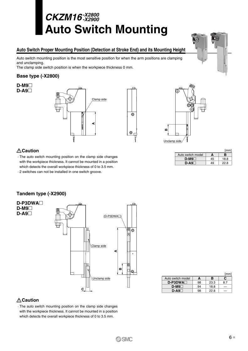
Auto Switch Proper Mounting Position (Detection at Stroke End) and its Mounting Height
Base type (-X2800)
Tandem type (-X2900)
D-P3DWAD-M9D-A9
Caution · The auto switch mounting position on the clamp side changes
with the workpiece thickness. It cannot be mounted in a position which detects the overall workpiece thickness of 0 to 3.5 mm.
Caution · The auto switch mounting position on the clamp side changes
with the workpiece thickness. It cannot be mounted in a position which detects the overall workpiece thickness of 0 to 3.5 mm.
· 2 switches can not be installed in one switch groove.
D-M9D-A9
[mm]Auto switch model A B C
D-P3DWA 98 23.3 8.7D-M9 94 18.8 —D-A9 98 22.8 —
[mm]Auto switch model A B
D-M9 45 18.8D-A9 49 22.8
CKZM16-X2800 -X2900
Auto Switch Mounting
Auto switch mounting position is the most sensitive position for when the arm positions are clamping and unclamping.The clamp side switch position is when the workpiece thickness 0 mm.
6 A
Safety Instructions Be sure to read “Handling Precautions for SMC Products” (M-E03-3) before using.
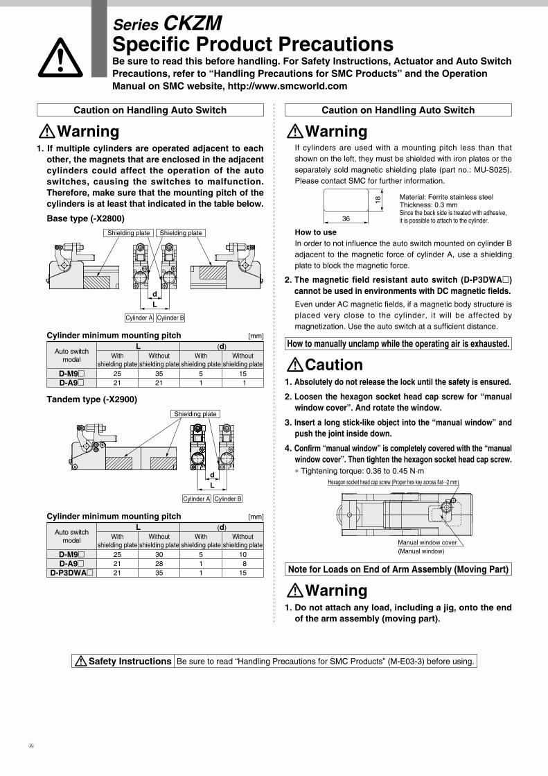
Be sure to read this before handling. For Safety Instructions, Actuator and Auto Switch Precautions, refer to “Handling Precautions for SMC Products” and the Operation Manual on SMC website, http://www.smcworld.com
Caution on Handling Auto Switch
WarningIf cylinders are used with a mounting pitch less than that shown on the left, they must be shielded with iron plates or the separately sold magnetic shielding plate (part no.: MU-S025). Please contact SMC for further information.
18
36
Material: Ferrite stainless steelThickness: 0.3 mmSince the back side is treated with adhesive, it is possible to attach to the cylinder.
How to useIn order to not influence the auto switch mounted on cylinder B adjacent to the magnetic force of cylinder A, use a shielding plate to block the magnetic force.
2. The magnetic field resistant auto switch (D-P3DWA) cannot be used in environments with DC magnetic fields.Even under AC magnetic fields, if a magnetic body structure is placed very close to the cylinder, it will be affected by magnetization. Use the auto switch at a sufficient distance.
How to manually unclamp while the operating air is exhausted.
Caution1. Absolutely do not release the lock until the safety is ensured.
2. Loosen the hexagon socket head cap screw for “manual window cover”. And rotate the window.
3. Insert a long stick-like object into the “manual window” and push the joint inside down.
4. Confirm “manual window” is completely covered with the “manual window cover”. Then tighten the hexagon socket head cap screw.* Tightening torque: 0.36 to 0.45 N·m
Manual window cover(Manual window)
Hexagon socket head cap screw (Proper hex key across flat···2 mm)
Note for Loads on End of Arm Assembly (Moving Part)
Warning1. Do not attach any load, including a jig, onto the end
of the arm assembly (moving part).
Caution on Handling Auto Switch
Warning1. If multiple cylinders are operated adjacent to each
other, the magnets that are enclosed in the adjacent cylinders could affect the operation of the auto switches, causing the switches to malfunction. Therefore, make sure that the mounting pitch of the cylinders is at least that indicated in the table below.
Base type (-X2800)
Shielding plateShielding plate
Cylinder BCylinder A
Ld
Cylinder minimum mounting pitch [mm]
Auto switch model
L (d)With
shielding plateWithout
shielding plateWith
shielding plateWithout
shielding plateD-M9 25 35 5 15D-A9 21 21 1 1
Tandem type (-X2900)
Shielding plate
Cylinder BCylinder A
Ld
Cylinder minimum mounting pitch [mm]
Auto switch model
L (d)With
shielding plateWithout
shielding plateWith
shielding plateWithout
shielding plateD-M9 25 30 5 10D-A9 21 28 1 8
D-P3DWA 21 35 1 15
Series CKZMSpecific Product Precautions
A


![Force Prediction and Cutting-Parameter Optimization in Micro ......micro-milling to reduce burrs on the workpiece surface. Zhang et al. [11] proposed a new universal instantaneous](https://static.fdocuments.net/doc/165x107/60d4f7b97877bd26fd2f1362/force-prediction-and-cutting-parameter-optimization-in-micro-micro-milling.jpg)
