Information for the Machine Tool Builder - · PDF fileMC 6341, CC 6106 2 TNC 640 †...
84
September 2011 TNC 640 HSCI Contouring Control for Machining Centers and Milling/Turning Machines Information for the Machine Tool Builder
Transcript of Information for the Machine Tool Builder - · PDF fileMC 6341, CC 6106 2 TNC 640 †...

September 2011
TNC 640 HSCIContouring Control for Machining Centers and Milling/Turning Machines
Information for the
Machine Tool Builder
MC 6341, CC 6106
2
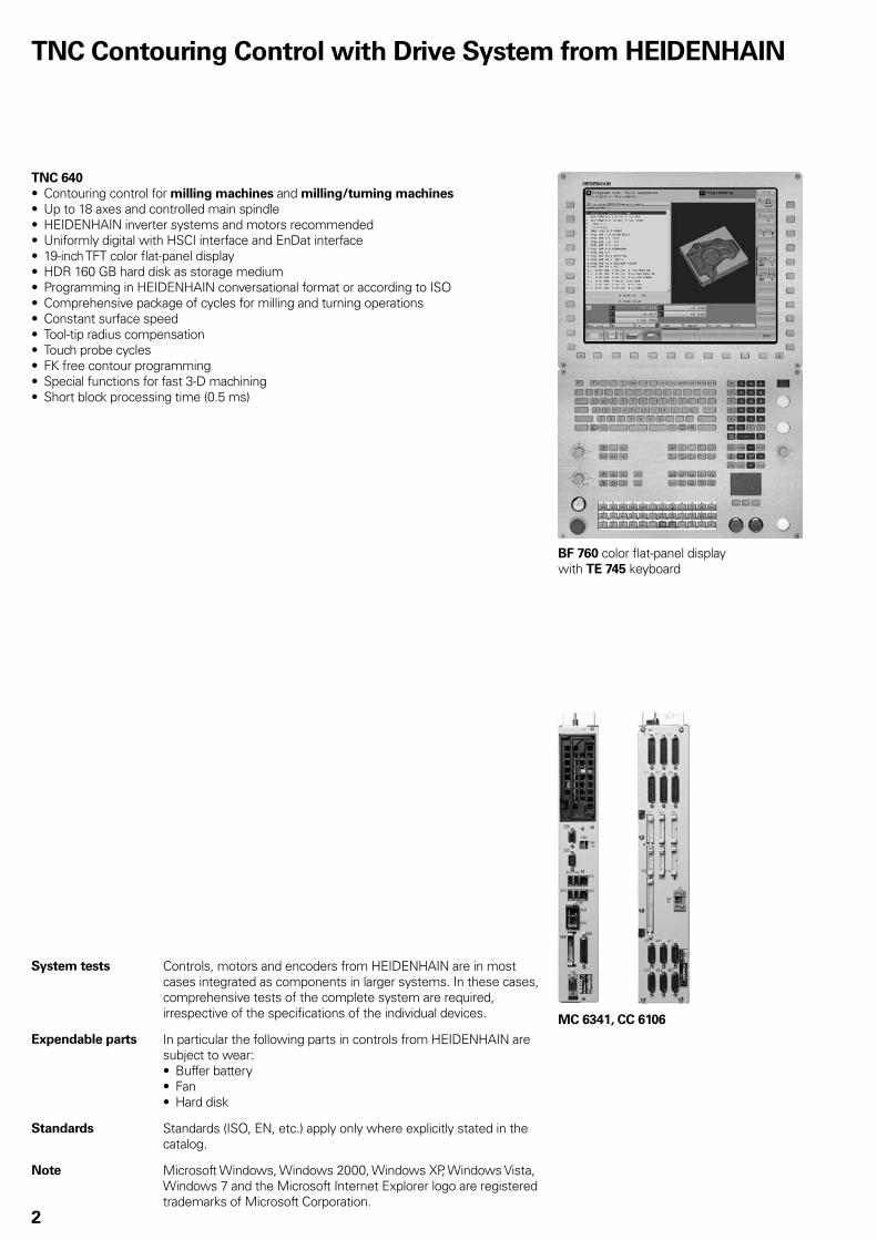
TNC 640
Contouring control for • milling machines and milling/turning machines
Up to 18 axes and controlled main spindle• HEIDENHAIN inverter systems and motors recommended• Uniformly digital with HSCI interface and EnDat interface• 19-inch TFT color fl at-panel display• HDR 160 GB hard disk as storage medium• Programming in HEIDENHAIN conversational format or according to ISO• Comprehensive package of cycles for milling and turning operations• Constant surface speed• Tool-tip radius compensation• Touch probe cycles• FK free contour programming• Special functions for fast 3-D machining• Short block processing time (0.5 ms)•
TNC Contouring Control with Drive System from HEIDENHAIN
System tests Controls, motors and encoders from HEIDENHAIN are in most cases integrated as components in larger systems. In these cases, comprehensive tests of the complete system are required, irrespective of the specifi cations of the individual devices.
Expendable parts In particular the following parts in controls from HEIDENHAIN are subject to wear:
Buffer battery• Fan• Hard disk•
Standards Standards (ISO, EN, etc.) apply only where explicitly stated in the catalog.
Note Microsoft Windows, Windows 2000, Windows XP, Windows Vista, Windows 7 and the Microsoft Internet Explorer logo are registered trademarks of Microsoft Corporation.
BF 760 color fl at-panel display with TE 745 keyboard

3
Contents
This catalog supersedes all previous editions, which thereby become invalid.
Subject to change without notice
The features and specifi cations described here apply for the following control and NC software version:
TNC 640 with NC software versions
340 590-01 (export license required)340 591-01 (no export license required)
Some of these specifi cations require particular machine confi gurations. Please note also that, for some functions, a special PLC program must be created by the manufacturer.If no explicit distinction is made between standard and FS components (FS = functional safety), then the data and other information apply to both versions (e.g. TE 745, TE 745 FS).
Page
Tables with Specifi cations, Machine Interfacing, User Functions and Accessories
4
Functional Safety 14
Digital Control Design 16
Control Systems 17
Cable Overviews 36
Technical Description 40
Overall Dimensions 64
Documentation 79
Service 80
Other HEIDENHAIN Controls 81
Subject Index 82
Please refer to the page references in the tables with the specifi cations.

4
Specifi cations
Specifi cations TNC 640 HSCI Page
Control systems 19” design 17
Main computer MC 6241 orMC 6341
18
Controller unit CC 6106 orCC 6108 orCC 6110 orUEC 111 (inverter and system PL integrated) orUEC 112 (inverter and system PL integrated)
22
Visual display unit BF 760 color fl at-panel TFT display 25
Operating panel TE 740 orTE 745 (integrated machine operating panel)
25
PLC inputs/outputs PL 6xxx series; or on UEC 11x 26
Inverter systems *
Compact inverters ✔ *
Modular inverters ✔ *
Axes1)
Max. 18 40
Rotary axes Max. 3 40
Synchronized axes ✔ 42
PLC axes ✔ 42
Spindle Milling: max. 2; second spindle can be controlled alternately with the fi rstTurning: 1Milling spindle or lathe spindle activated via NC command
45
Shaft speed2) Max. 60 000 min–1 45
Operating-mode switchover ✔ 45
Position-controlled spindle ✔ 45
Oriented spindle stop ✔ 45
Gear shifting ✔ 45
NC program memory Approx. 144 GB on HDR hard disk –
Input resolution and display step 40
Linear axes 1 µm, 0.01 µm with option 23 40
Rotary axes 0.001°; 0.000 01° with option 23 40
1) As ordered2) On motors with two pole pairs* For further information, refer to the Inverter Systems brochure (ID 622 420-xx)

5
Specifi cations TNC 640 HSCI Page
Functional safety With FS components, SPLC and SKERN 14
For applications up to SIL 2 according to EN 61 508• Category 3, PL d according to EN ISO 13 849-1:2008•
14
Interpolation MC 6xxx
Straight line In 4 axes; in 5 axes with option 9 *
Circle In 2 axes; in 3 axes with option 9 *
Helix ✔ *
Axis feedback control 46
With following error ✔ 46
With feedforward ✔ 46
Axis clamping ✔ 40
Maximum feed rate · screw pitch [mm]
Cycle times of main computer MC 6xxx 47
Block processing 0.5 ms 48
Cycle times of controller unit CC 61xx/UEC 11x 47
Path interpolation 3 ms 47
Fine interpolation Single speed: 0.2 msDouble speed: 0.1 ms (option 49)
47
Position controller Single speed: 0.2 msDouble speed: 0.1 ms (option 49)
47
Speed controller Single speed: 0.2 msDouble speed: 0.1 ms (option 49)
47
Current controller fPWM TINT 3 333 Hz 150 µs 4 000 Hz 125 µs 5 000 Hz 100 µs 6 666 Hz 75 µs with option 49 8 000 Hz 60 µs with option 4910 000 Hz 50 µs with option 49
22
Permissible temperature range Operation: In electrical cabinet: 5 °C to 40 °CIn operating panel: 0 °C to 50 °C
Storage: –20 °C to +60 °C
–
* For further information, refer to the TNC 640 brochure (ID 892 916-xx)
60 000 min–1
No. of pole pairs in motor

6
Machine Interfacing
Machine interfacing TNC 640 Page
Error compensation ✔ 50
Linear axis error ✔ 50
Nonlinear axis error ✔ 50
Backlash ✔ 50
Reversal peaks with circular movement ✔ 50
Hysteresis ✔ 50
Thermal expansion ✔ 50
Stick-slip friction ✔ 50
Sliding friction ✔ 50
Integral PLC 55
Program format Statement list 55
Program input on the TNC ✔ 55
Program input via PC ✔ 55
Symbolic PLC-NC interface ✔
PLC memory At least 1 GB on hard disk 55
PLC cycle time Typically 21 ms, adjustable 55
PLC inputs/outputs1) 1 x PLB 62xx or UEC 11x and max. 7 x PLB 61xx and 1 x TE 745 (with
integrated MB) or PLB 6001 (max. total: 9 components)26
PLC inputs, 24 V DC Via PL or UEC 11x 26
PLC outputs, 24 V DC Via PL or UEC 11x 26
Analog inputs, ±10 V DC Via PL 26
Inputs for PT 100 thermistors Via PL 26
Analog outputs, ±10 V DC Via PL 26
PLC functions ✔ 56
Small PLC window ✔ 56
PLC soft keys ✔ 56
PLC positioning ✔ 56
PLC basic program ✔ 58
Integration of applications 57
High-level language programming Python programming language used in combination with the PLC (option 46) 57
User interface can be custom-designed Inclusion of specifi c user interfaces from the machine tool builder (option 46) 571) Further PLC inputs/outputs via PL 550 for connection to MC 6xxx with PROFIBUS-DP interface

7
Machine interfacing TNC 640 Page
Encoder inputs CC 6106 CC 6108 CC 6110 UEC 111 UEC 112 49
Position 6 8 10 4 5 49
Incremental 1 VPP 49
Absolute EnDat 2.2 49
Speed 6 8 10 4 5 49
Incremental 1 VPP 49
Absolute EnDat 2.2 49
Nominal-value outputs CC 6106 CC 6108 CC 6110 UEC 111 UEC 112 23
PWM 6 8 10 – – 23
Motor connections – – – 4 5 24
Commissioning and diagnostic aids 53
DriveDiag Software for diagnosis of digital drive systems 53
TNCopt Software for putting digital control loops into service 53
Confi gDesign Software for creation of the machine confi guration 53
Integrated oscilloscope ✔ 54
Trace function ✔ 54
Logic diagram ✔ 54
API DATA function ✔ 54
Table function ✔ 54
OnLine Monitor (OLM) ✔ 53
Log ✔ 54
TNCscope ✔ 54
Bus diagnosis ✔ 54
Data interfaces 60
Ethernet (100BaseT) ✔ 60
USB 2.0 ✔ 60
RS-232-C/V.24 ✔ 60
Protocols 60
Standard data transfer ✔ 60
Blockwise data transfer ✔ 60
LSV2 ✔ 60

8
Accessories
Accessories TNC 640 Page
Electronic handwheels One HR 410, HR 130, or up to three HR 150 via HRA 110 30
Touch probes One TS 220, TS 440, TS 444, TS 640 or TS 740 workpiece touch probe• One TT 140 or TL tool touch probe•
35
PLC input/output systems With HSCI interface 26
Basic module System PL1) For 4 I/O modules: PLB 6204
PLB 6204 FSFor 6 I/O modules: PLB 6206 PLB 6206 FSFor 8 I/O modules: PLB 6208 PLB 6208 FS
26
Expansion PL For four I/O modules: PLB 6104 PLB 6104 FSFor six I/O modules: PLB 6106 PLB 6106 FSFor eight I/O modules: PLB 6108 PLB 6108 FS
26
I/O modules PLD-H 16-08-00: 16 digital inputs and 8 digital outputs, 24 VPLD-H 08-16-00: 8 digital inputs and 16 digital outputs, 24 VPLD-H 08-04-00 FS: 8 digital inputs and 4 digital outputs, 24 VPLD-H 04-08-00 FS: 4 digital inputs and 8 digital outputs, 24 VPLA-H 08-04-04: 8 analog inputs ± 10 V, 4 analog outputs ± 10 V and
4 analog PT 100 inputs
27
HSCI adapter PLB 6001: For connection of an OEM machine operating panel 32
PLC input/output systems With PROFIBUS-DP interface 28
Basic module PLB 550 for four I/O modules 28
I/O modules PLD 16-8: 16 digital inputs and 8 digital outputs, 24 VPLA 4-4: 4 analog inputs ± 10 V, and 4 analog inputs for PT 100
28
Machine operating panel Integrated in TE 745 or• PLB 6001 (HSCI adapter for OEM operating panel)•
25
32
Analog module CMA-H 04-04-00: Additional module for analog axes/spindles in the HSCI system
32
USB hub ✔ 60
PLC basic program ✔ 58
TNC 640 programming station Control software for PCs for programming, archiving, and training
IPC 6341 Industrial PC with Windows 7 21
1) Integrated in UEC 11x, otherwise necessary once in each HSCI control system

9
Accessories TNC 640 Page
Software
PLCdesign1) PLC development software 57
KinematicsDesign1) Software for kinematic confi guration 52
TNCremo2) Data transfer software 61
TNCremoPlus2) Data transfer software with live-screen function 61
Confi gDesign1) Software for confi guring the machine parameters 53
CycleDesign1) Software for creating cycle structures 59
TNCscope1) Software for data recording 54
DriveDiag1) Software for diagnosis of digital control loops 53
TNCopt1) Software for putting digital control loops into service 53
IOconfi g1) Software for confi guring PLC I/O and PROFIBUS-DP components 27
TeleService1) Software for remote diagnostics, monitoring, and operation 54
RemoTools SDK1) Function library for developing customized applications for communication
with HEIDENHAIN controls61
1) Available to registered customers for downloading from the Internet2) Available to all customers (without registration) for downloading from the Internet

10
User Functions
User functions
Sta
nd
ard
Op
tio
n
Brief description •
•
0-77778
Basic version: 3 axes plus spindle4th NC axis plus auxiliary axisor
a total of 14 additional NC axes or 13 additional NC axes plus second spindle
Digital current and spindle speed control
Program entry ••
HEIDENHAIN conversationalDIN/ISO
Position data •••
Nominal positions for lines and arcs in Cartesian coordinates or polar coordinatesIncremental or absolute dimensionsDisplay and entry in mm or inches
Tool compensation ••
9
Tool radius in the working plane and tool lengthRadius-compensated contour look-ahead for up to 99 blocks (M120)Three-dimensional tool-radius compensation for changing tool data without having to recalculate
an existing program
Tool tables • Multiple tool tables with any number of tools
Constant contour speed ••
Relative to the path of the tool centerRelative to the tool’s cutting edge
Parallel operation • Creating a program with graphic support while another program is being run
3-D machining 9999
Motion control with minimum jerk3-D tool compensation through surface normal vectorsKeeping the tool normal to the contourTool radius compensation normal to the tool direction
Rotary table machining 88
Programming of cylindrical contours as if in two axesFeed rate in mm/min
Contour elements •••••••
5050
Straight lineChamferCircular pathCircle centerCircle radiusTangentially connecting circular arcCorner roundingRecessUndercut
Approaching and
departing the contour
••
Via straight line: tangential or perpendicularVia circular arc
FK free contour
programming
• FK free contour programming in HEIDENHAIN conversational format with graphic support for workpiece drawings not dimensioned for NC
Program jumps •••
SubroutinesProgram-section repeatCalling any program as a subroutine
11
User functions
Sta
nd
ard
Op
tio
n
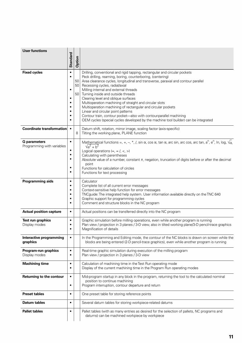
Fixed cycles ••
•
••••••
5050
50
Drilling, conventional and rigid tapping, rectangular and circular pocketsPeck drilling, reaming, boring, counterboring, (centering)Area clearance cycles, longitudinal and transverse, paraxial and contour parallelRecessing cycles, radial/axialMilling internal and external threadsTurning inside and outside threadsClearing level and oblique surfacesMultioperation machining of straight and circular slotsMultioperation machining of rectangular and circular pocketsLinear and circular point patternsContour train, contour pocket—also with contour-parallel machiningOEM cycles (special cycles developed by the machine tool builder) can be integrated
Coordinate transformation •8
Datum shift, rotation, mirror image, scaling factor (axis-specifi c)Tilting the working plane, PLANE function
Q parameters
Programming with variables•
•••
••
Mathematical functions =, +, –, *, /, sin Þ, cos Þ, tan Þ, arc sin, arc cos, arc tan, an, en, In, log, √a, √a2 + b2
Logical operations (=, = /, <, >)Calculating with parenthesesAbsolute value of a number, constant þ, negation, truncation of digits before or after the decimal
pointFunctions for calculation of circlesFunctions for text processing
Programming aids ••••••
CalculatorComplete list of all current error messagesContext-sensitive help function for error messagesTNCguide: The integrated help system. User information available directly on the TNC 640Graphic support for programming cyclesComment and structure blocks in the NC program
Actual position capture • Actual positions can be transferred directly into the NC program
Test run graphics
Display modes•••
Graphic simulation before milling operations, even while another program is runningPlan view / projection in 3 planes / 3-D view, also in tilted working plane/3-D pencil-trace graphicsMagnifi cation of details
Interactive programming
graphics
• In the Programming and Editing mode, the contour of the NC blocks is drawn on screen while the blocks are being entered (2-D pencil-trace graphics), even while another program is running
Program-run graphics
Display modes••
Real-time graphic simulation during execution of the milling programPlan view / projection in 3 planes / 3-D view
Machining time ••
Calculation of machining time in the Test Run operating modeDisplay of the current machining time in the Program Run operating modes
Returning to the contour •
•
Mid-program startup in any block in the program, returning the tool to the calculated nominal position to continue machining
Program interruption, contour departure and return
Preset tables • One preset table for storing reference points
Datum tables • Several datum tables for storing workpiece-related datums
Pallet tables • Pallet tables (with as many entries as desired for the selection of pallets, NC programs and datums) can be machined workpiece by workpiece

12
User Functions
User functions
Sta
nd
ard
Op
tio
n
Touch probe cycles ••••
Touch probe calibrationCompensation of workpiece misalignment, manual or automaticDatum setting, manual or automaticAutomatic tool and workpiece measurement
Parallel secondary axes ••
•
Compensating movement in the secondary axis U, V, W through the principal axis X, Y, ZIncluding movements of parallel axes in the position display of the associated principal axis (sum
display)Defi ning the principal and secondary axes in the NC program makes it possible to run programs
on different machine confi gurations
Conversational languages •
41
English, German, Chinese (traditional, simplifi ed), Czech, Danish, Dutch, Finnish, French, Hungarian, Italian, Polish, Portuguese, Russian (Cyrillic), Spanish, Swedish
For more conversational languages, see Options
13
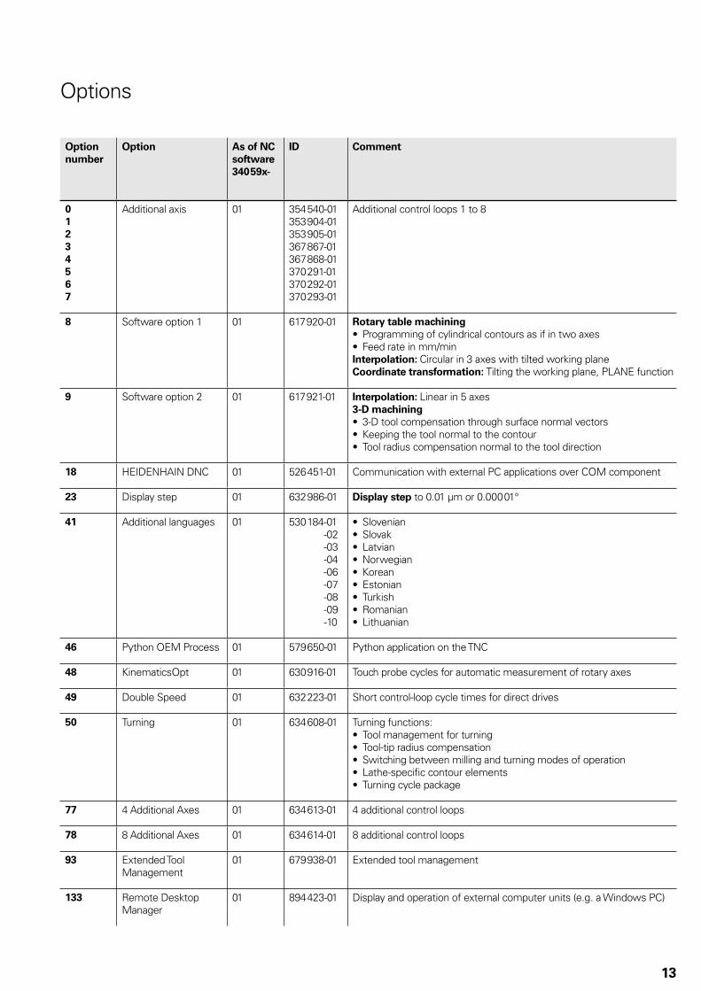
Options
Option
number
Option As of NC
software
340 59x-
ID Comment
0
1
2
3
4
5
6
7
Additional axis 01 354 540-01353 904-01353 905-01367 867-01367 868-01370 291-01370 292-01370 293-01
Additional control loops 1 to 8
8 Software option 1 01 617 920-01 Rotary table machining
Programming of cylindrical contours as if in two axes• Feed rate in mm/min•
Interpolation: Circular in 3 axes with tilted working planeCoordinate transformation: Tilting the working plane, PLANE function
9 Software option 2 01 617 921-01 Interpolation: Linear in 5 axes3-D machining
3-D tool compensation through surface normal vectors• Keeping the tool normal to the contour• Tool radius compensation normal to the tool direction•
18 HEIDENHAIN DNC 01 526 451-01 Communication with external PC applications over COM component
23 Display step 01 632 986-01 Display step to 0.01 µm or 0.000 01°
41 Additional languages 01 530 184 -01-02-03-04-06-07-08-09-10
Slovenian• Slovak• Latvian• Norwegian• Korean• Estonian• Turkish• Romanian• Lithuanian•
46 Python OEM Process 01 579 650-01 Python application on the TNC
48 KinematicsOpt 01 630 916-01 Touch probe cycles for automatic measurement of rotary axes
49 Double Speed 01 632 223-01 Short control-loop cycle times for direct drives
50 Turning 01 634 608-01 Turning functions:Tool management for turning• Tool-tip radius compensation• Switching between milling and turning modes of operation• Lathe-specifi c contour elements• Turning cycle package•
77 4 Additional Axes 01 634 613-01 4 additional control loops
78 8 Additional Axes 01 634 614-01 8 additional control loops
93 Extended Tool Management
01 679 938-01 Extended tool management
133 Remote Desktop Manager
01 894 423-01 Display and operation of external computer units (e.g. a Windows PC)
����
����
� �
������� �
����
14
Functional safety (FS)
Basic principle Controls from HEIDENHAIN with functional safety meet safety integrity level 2 (SIL 2) as per the EN 61 508 standard, as well as the performance level “d” as per EN ISO 13 849-1 (which replaced EN 954-1). These standards describe the assessment of safety-related systems, for example based on the failure probabilities of integrated components and subsystems. This modular approach helps the manufacturers of safety-related systems to implement their complete systems, because they can begin with subsystems that have already been qualifi ed. Safety-related position encoders, the TNC 640 control and functional safety accommodate this concept. Two redundant safety channels that work independently of each other are the foundation for controls with functional safety. All safety-relevant signals are captured, processed and output via two channels. Errors are detected by mutual comparison of the states and data in the two channels. This way, the occurrence of just one fault in the control does not lead to the safety functions being incapacitated.
Design The safety-related controls from HEIDENHAIN have a dual-channel design with mutual monitoring. The SPLC (safety-related PLC program) and SKERN (safe core software) processes are the basis of the two redundant systems. The two software processes run on the MC main computer (CPU) and CC controller unit (DSP) components. The dual-channel structure of the MC and CC is also used in the PL 6xxx FS input/output systems and the MB 6xx FS machine operating panel. This means that all safety-relevant signals (e.g. permissive buttons and keys, door contacts, emergency stop button) are captured via two channels, and are evaluated independently of each other by the MC and CC. The MC and CC use separate channels to also address the power stages, and to stop the drives in case of an error.
Components In systems with functional safety, certain hardware components assume safety-relevant tasks. Systems with FS may consist of only those safety-relevant components, including their variants, which HEIDENHAIN has approved for use!
Control components with functional safety are recognizable by the suffi x FS after the model designation, e.g. TE 745 FS.
MB and TE An MB machine operating panel with FS is absolutely necessary for systems with functional safety (integrated in TE 745 FS). Only on such a machine operating panel do all keys have a dual-channel design. Axes can be moved without additional permissive keys.
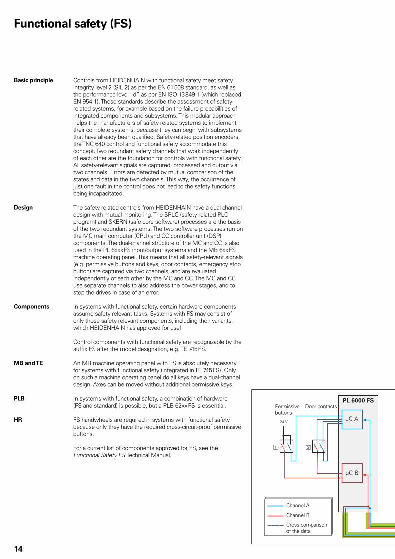
PLB In systems with functional safety, a combination of hardware (FS and standard) is possible, but a PLB 62xx FS is essential.
HR FS handwheels are required in systems with functional safety because only they have the required cross-circuit-proof permissive buttons.
For a current list of components approved for FS, see the Functional Safety FS Technical Manual.
Door contactsPermissive buttons
Channel A
Channel B
Cross comparison of the data

��������
���� ����
����� �����
�������
���
����� �
���
�
TE 745
15
Safety functions The following safety functions are integrated in the hardware and software.
Safe stop reactions (SS0, SS1, SS2)• Safe torque off (STO)• Safe operating stop (SOS)• Safely limited speed (SLS)• Safely limited position (SLP)• Safe brake control (SBC)• Safe operating modes in accordance with EN 12• 417:
Operating mode 1 – Automated or production mode -Operating mode 2 – Set-up mode -Operating mode 3 – Manual intervention -Operating mode 4 – Advanced manual intervention, process -monitoring
Please note:At the time of introduction, the TNC 640 does not yet have the complete scope of functions for ensuring functional safety on all machine types. Before planning a machine with functional safety, please inform yourself of whether the current scope of features suffi ces for your machine design.
Activation of
functional safety
If the control identifi es a PLB 62xx FS in the system during booting, functional safety is activated. In this case, it is essential that the following prerequisites be fulfi lled:
Functional safety versions of safety-related control components • (e.g. TE 745 FS, HR 410 FS)Safety-related SPLC program• Confi guration of safe machine parameters• Wiring of the machine for systems with functional safety•
Functional safety cannot be activated or deactivated by parameter.
For more
information
For more information on the topic of functional safety, refer to the Technical Information documents Safety-Related Control Technology for Machine Tools and Safety-Related Position Encoders.
For details, see the Functional Safety FS Technical Manual.Your contact person at HEIDENHAIN will be glad to answer any questions concerning the TNC 640 with functional safety.
Power amplifi er
EnDat masterSafety-related position measuring system
EnDat 2.2 data transmission path
Emergency stop button
Inverter
system
Encoder

16
Digital Control Design
Uniformly digital In the uniformly digital control design from HEIDENHAIN, all components are connected to each other via purely digital interfaces: The control components are connected via HSCI (HEIDENHAIN Serial Controller Interface), the new real-time protocol from HEIDENHAIN for Fast Ethernet, and the encoders are connected via EnDat 2.2, the bidirectional interface from HEIDENHAIN. This achieves a high degree of availability for the entire system. It can be diagnosed and is immune to noise—from the main computer to the encoder. These outstanding properties of the uniformly digital design from HEIDENHAIN guarantee not only very high accuracy and surface quality, but rapid traverse speeds as well. Please refer to the Uniformly Digital Technical Information sheet for more detailed information.
HSCI HSCI, the HEIDENHAIN Serial Controller Interface, connects the main computer, controller(s) and other control components. HSCI is based on 100BaseT Ethernet hardware. A special interface component developed by HEIDENHAIN has shortened cycle times for data transfer.
Main advantages of the control design with HSCI:
Hardware platform for fl exible and scalable control system • (e.g. decentral axis systems)High noise immunity due to digital communication between • componentsHardware basis for the implementation of “functional safety”• Simpler wiring (initial operation, confi guration)• Inverters remain connected via proven PWM interface• Greater cable lengths in the entire system (HSCI up to 70 m)• More control loops (18 axes, alternately 2 spindles)• More PLC inputs and outputs• Controller units can be installed elsewhere•
CC or UEC controller units, up to eight PL 6xxx input/output modules, and an MB machine operating panel can be connected to the serial HSCI bus of the MC main computer. The HR handwheel is connected directly to the machine operating panel.
The combination of visual display unit and main computer housed in the operating panel is especially advantageous. All that is required is the power supply and an HSCI line to the controller in the electrical cabinet.
The maximum permissible number of individual HSCI participants is listed below.
HSCI components Maximum number
MC HSCI master 1 in the system
CC, UEC HSCI slave 4 drive-control motherboards (distributed to CC, UEC as desired)
TE 745, PLB 6001 HSCI slave 1 in the system Total of up to 9 components
PLB 62xx HSCI slave 1 in the system (not with UEC 11x)
PLB 61xx HSCI slave 7 in the system
HR handwheel On MB 7xx or PLB 6001
1 in the system
PLD-H-xx-xx FS In PLB 6xxx FS 8 in the system
PLD-H-xx-xx In PLB 6xxx (FS) 64 in the system

17
TNC 640 HSCI Control Systems
Overview
The TNC 640 contouring control includes various components, which can be selected and combined to fi t the application.
Type Page
Main computer MC 6241 MC 6341 18
Processor Pentium M Pentium Dual Core
Storage medium HDR hard disk 19
NC software license SIK 19
Controller unit 6 control loops CC 6106 23
8 control loops CC 6108 23
10 control loops CC 6110 23
12 control loops CC 6106 + CC 6106 23
14 control loops CC 6108 + CC 6106 23
16 control loops CC 6108 + CC 6108 23
18 control loops CC 6106 + CC 6106 + CC 6106 or CC 6110 + CC 6108 23
20 control loops CC 6110 + CC 6110 23
Controller unit
with integral
inverter
4 control loops UEC 1111)
24
5 control loops UEC 1121)
24
Power supply PSL 130/PSL 135 29
Visual display unit BF 760 25
Operating panel TE 740 or TE 745 (with integrated MB) 25
Machine operating panel TE 745 (MB integrated) orPLB 6001 (HSCI adapter for OEM operating panel)
25
32
PLC inputs/outputs1)
PL 6xxx/PL 550 series 26
Connecting cables 36
Electronic handwheels HR 410/HR 130 or HR 150 30
Touch probes Workpiece measurement
TS 220/TS 440/TS 444/TS 640 or TS 740 35
Tool measurement TT 140 or TL 35
Industrial PC IPC 6341 21
1) Please note:
The MC 6xxx main computer does not have any PLC inputs/outputs. Therefore one PL 62xx or one UEC 11x is necessary for each control. They feature safety-relevant inputs/outputs as well as the connections for touch probes.
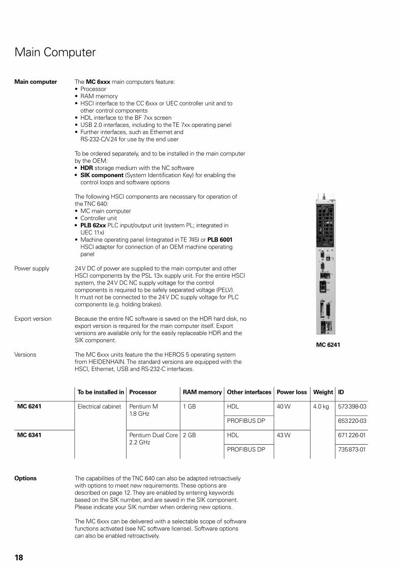
MC 6241
18
Main computer The MC 6xxx main computers feature:Processor• RAM memory• HSCI interface to the CC 6xxx or UEC controller unit and to • other control componentsHDL interface to the BF 7xx screen• USB 2.0 interfaces, including to the TE 7xx operating panel• Further interfaces, such as Ethernet and • RS-232-C/V.24 for use by the end user
To be ordered separately, and to be installed in the main computer by the OEM:
HDR• storage medium with the NC softwareSIK component• (System Identifi cation Key) for enabling the control loops and software options
The following HSCI components are necessary for operation of the TNC 640:
MC main computer• Controller unit• PLB 62xx• PLC input/output unit (system PL; integrated in UEC 11x)Machine operating panel (integrated in TE 745) or • PLB 6001 HSCI adapter for connection of an OEM machine operating panel
Power supply 24 V DC of power are supplied to the main computer and other HSCI components by the PSL 13x supply unit. For the entire HSCI system, the 24 V DC NC supply voltage for the control components is required to be safely separated voltage (PELV). It must not be connected to the 24 V DC supply voltage for PLC components (e.g. holding brakes).
Export version Because the entire NC software is saved on the HDR hard disk, no export version is required for the main computer itself. Export versions are available only for the easily replaceable HDR and the SIK component.
Versions The MC 6xxx units feature the the HEROS 5 operating system from HEIDENHAIN. The standard versions are equipped with the HSCI, Ethernet, USB and RS-232-C interfaces.
Main Computer
To be installed in Processor RAM memory Other interfaces Power loss Weight ID
MC 6241 Electrical cabinet Pentium M1.8 GHz
1 GB HDL 40 W 4.0 kg 573 398-03
PROFIBUS DP 653 220-03
MC 6341 Pentium Dual Core2.2 GHz
2 GB HDL 43 W 671 226-01
PROFIBUS DP 735 873-01
Options The capabilities of the TNC 640 can also be adapted retroactively with options to meet new requirements. These options are described on page 12. They are enabled by entering keywords based on the SIK number, and are saved in the SIK component. Please indicate your SIK number when ordering new options.
The MC 6xxx can be delivered with a selectable scope of software functions activated (see NC software license). Software options can also be enabled retroactively.

19
Main Computer—HDR, SIK Component
Storage medium The storage medium is removable and must be ordered separately from the main computer. It contains the NC software 340 59x-xx. An HDR hard disk serves as storage medium.
HDR hard disk
SIK component
SIK component The SIK component contains the NC software license for enabling control loops and software options. It gives the main computer an unambiguous ID code—the SIK number. The SIK component is ordered and shipped separately. It must be inserted in a special slot in the MC 6xxx main computer.
The SIK component with the NC software license is available in various versions, depending on the main computer and the enabled control loops. Further control loops—up to the maximum number available (see Controller Unit)—can be enabled later by entering a keyword. HEIDENHAIN provides the keyword, which is based on the SIK number.
When ordering, please indicate the SIK number of your control.
When the keywords are entered in the control, they are saved in the SIK component. This enables and activates the options. Should service become necessary, the SIK component must be inserted in the replacement control to enable all required options.
Free
capacity
For main
computer
Export license
required
No export license
required
HDR hard disk 144 GB MC 6241MC 6341
ID 617 779-01 ID 617 779-51
Master keyword (general key)
There is a master keyword (general key) for putting the TNC 640 into service that will unlock all options for a duration of 90 days. After this period, only those options with the correct keywords will be active. The general key is activated via a soft key.
Software Key Generator (accessory)
This PC software makes it possible to generate an activation code for software options on HEIDENHAIN controls. The selected option is enabled for a limited time (10 to 90 days). It can only be enabled once. You generate the desired activation code by entering the SIK number, the option to be enabled, the duration and a manufacturer-specifi c password. The enabling is independent of the general key.

20
Individual control loops ID
1st additional control loop 354 540-01
2nd additional control loop 353 904-01
3rd additional control loop 353 905-01
4th additional control loop 367 867-01
5th additional control loop 367 868-01
6th additional control loop 370 291-01
7th additional control loop 370 292-01
8th additional control loop 370 293-01
Enabling further
control loops
Further control loops can be enabled either as groups or individually. The combination of control-loop groups and individual control loops makes it possible to enable any number of control loops. Up to 20 control loops are possible.
Control-loop groups Option ID
4 additional control loops 77 634 613-01
8 additional control loops 78 634 614-01
NC software license
and enabling of
control loops
depending on CC(italics: export version)
Acti
ve c
on
tro
l
loo
ps
Recommended combinations NC software licenseC
C 6
106
CC
6108
CC
611
0
2 x
CC
6106
CC
6106
CC
6108
2 x
CC
6108
Without
option
Incl. Software
Option 1
Incl. Software
Options 1 + 2
Incl. Software
Options 1 and 2,
and option 50
SIK ID SIK ID SIK ID SIK ID
4 674 989-20674 989-70
674 989-09674 989-59
674 989-01674 989-51
674 989-28674 989-78
5 674 989-24674 989-74
674 989-17674 989-67
674 989-02674 989-52
674 989-29674 989-79
6 674 989-25674 989-75
674 989-18674 989-68
674 989-03674 989-53
674 989-30674 989-80
7 674 989-26674 989-76
674 989-19674 989-69
674 989-04674 989-54
674 989-31674 989-81
8 674 989-27674 989-77
674 989-23674 989-73
674 989-05674 989-55
674 989-32674 989-82
9 674 989-06674 989-56
674 989-33674 989-83
10 674 989-07674 989-57
674 989-34674 989-84
11 674 989-10674 989-60
674 989-35674 989-85
12 Only through subsequent enabling of control loops (additional axes)
674 989-11674 989-61
674 989-36674 989-86
13 674 989-12674 989-62
674 989-37674 989-87
14 674 989-13674 989-63
674 989-38674 989-88
15 674 989-14674 989-64
674 989-39674 989-89
16 674 989-15674 989-65
674 989-40674 989-90
17 – 20
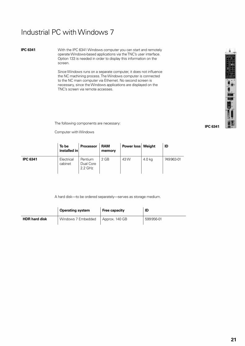
IPC 6341
21
Industrial PC with Windows 7
IPC 6341 With the IPC 6341 Windows computer you can start and remotely operate Windows-based applications via the TNC’s user interface. Option 133 is needed in order to display this information on the screen.
Since Windows runs on a separate computer, it does not infl uence the NC machining process. The Windows computer is connected to the NC main computer via Ethernet. No second screen is necessary, since the Windows applications are displayed on the TNC’s screen via remote accesses.
The following components are necessary:
Computer with Windows
To be
installed in
Processor RAM
memory
Power loss Weight ID
IPC 6341 Electrical cabinet
Pentium Dual Core2.2 GHz
2 GB 43 W 4.0 kg 749 963-01
A hard disk—to be ordered separately—serves as storage medium.
Operating system Free capacity ID
HDR hard disk Windows 7 Embedded Approx. 140 GB 599 956-01

CC 6106
22
Controller Unit
Controller unit Due to the very short cycle times of the position, speed and current controllers, the controller units from HEIDENHAIN are equally suited for conventional drives, for direct drives (linear motors, torque motors) and for HSC spindles. They permit a high loop gain and short reaction times to changing machining forces, and so make the high contour accuracy and surface quality of the workpiece possible.
Single-speed Double-speed
Single-speed control loops are usually suffi cient for linear or torque motors and for conventional axes. Double-speed control
loops (option 49) are preferred for HSC spindles and axes that are diffi cult to control. In the default setting, all axes are set to single speed. Each axis that is switched from single speed to double speed may reduce the number of available control loops by one. PWM frequencies greater than 5 kHz require double-speed control loops, for which option 49 must be enabled.
Cycle times With fPWM Current
controller
Speed controller Position
controllerSingle-
speed
Double-
speed
3 333 Hz 150 µs 300 µs 150 µs Same as speed
controller 4 000 Hz 125 µs 250 µs 125 µs
5 000 Hz 100 µs 200 µs 100 µs
6 666 Hz1) 75 µs 150 µs 150 µs
8 000 Hz1) 60 µs 125 µs 125 µs
10 000 Hz1) 50 µs 100 µs 100 µs
1) Possible only with option 49
Number of control loops
The number of enabled control loops depends on the SIK (see Main Computer), or on additionally enabled control loops, which can also be ordered as needed at a later date.
Versions Modular CC 61xx controller units with PWM interface to the • invertersCompact UEC 11x controller units with integrated inverter•
Controller units and main computers operate in any desired combination.

c
c
23
Combination Length Dimension
c
ID
2 x CC 6108 or2x CC 6110 orCC 6108 and CC 6110
300 mm1) 26.5 mm 325 816-22
2 x CC 6106 80 mm 31.5 mm 325 816-151) In order to reduce the voltage drop, the long ribbon cable is led
doubled.
Ribbon cable for
supply voltage
Additional ribbon cables are necessary if multiple CC 6xxx units are combined.
The short ribbon cables (ID 352 816-15) included in delivery are not necessary for combinations with CC 6108 and/or CC 6110. They are only necessary for connecting sockets X69 A and X69 B if the CC units are used separately.
For more information about connecting a CC 6xxx to a supply unit via ribbon cables, see the Inverter Systems brochure.
For more than 10 control loops, an HSCI line is used to combine the controller units. For example:CC 6106 + CC 6106 for up to 12 control loopsCC 6106 + CC 6108 for up to 14 control loopsCC 6110 + CC 6108 for up to 18 control loops
Constraints:Max. 20 control loops for max. 18 axes + 2 spindles (second • spindle can be controlled alternately with the fi rst spindle) can be activatedA maximum of four drive-control main boards are allowed in the • HSCI system (the CC 6106 contains one main board, the CC 6108/CC 6110 each contain two main boards).
CC 61xx The CC 61xx controller units feature:Position controller• Speed controller• Current controller• HSCI interfaces• PWM interfaces to the UM, UR, UE power modules• Interfaces to the speed and position encoders• Interfaces for power supply (via inverter or PSL 135)• SPI interfaces for expansion modules (e.g. CMA-H)•
CC 6106 CC 6108 CC 6110
Digital control loops Max. 6 (single speed) Max. 8 (single speed) Max. 10 (single speed)
Speed inputs 6 x 1 VPP or EnDat 2.2 8 x 1 VPP or EnDat 2.2 10 x 1 VPP or EnDat 2.2
Position inputs 6 x 1 VPP or EnDat 2.2 8 x 1 VPP or EnDat 2.2 10 x 1 VPP or EnDat 2.2
PWM outputs 6 8 10
Weight 4.1 kg 4.7 kg 4.8 kg
ID 662 636-01 662 637-01 662 638-01
24
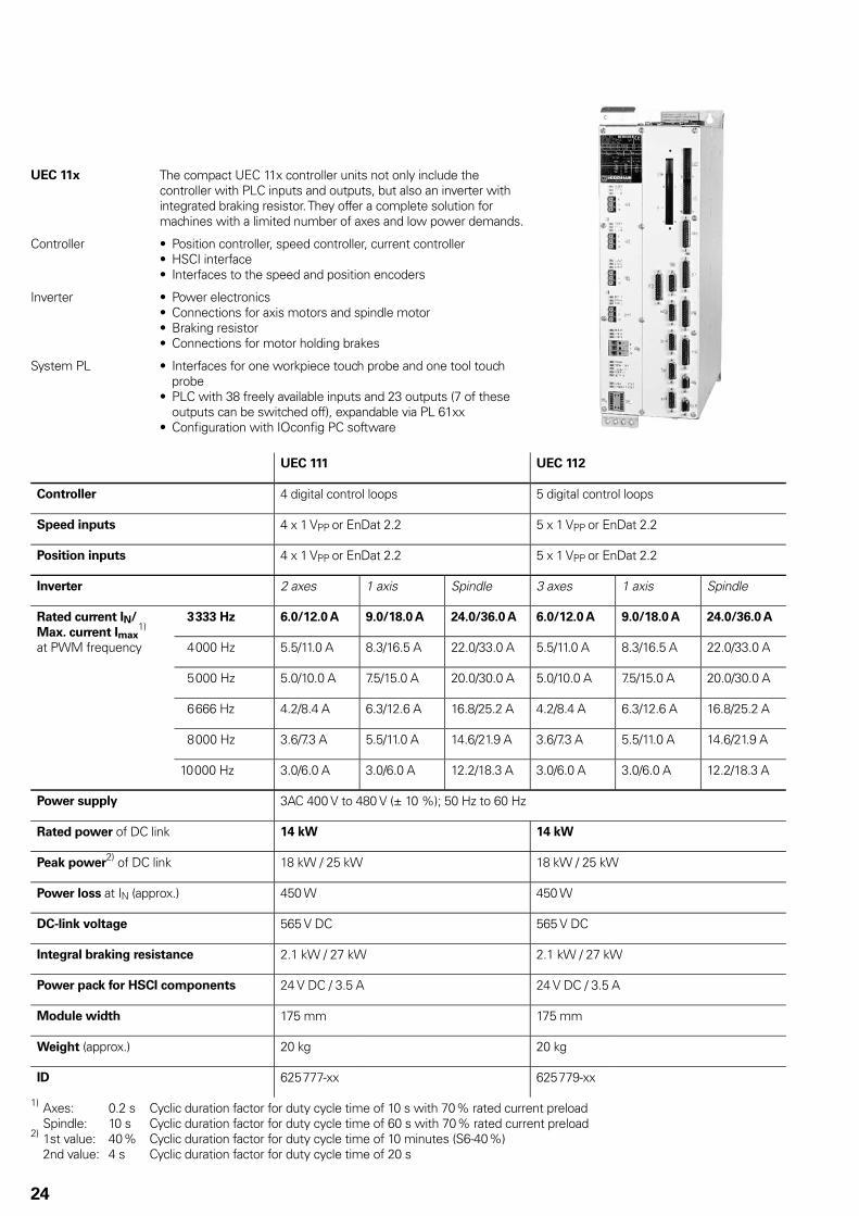
UEC 11x The compact UEC 11x controller units not only include the controller with PLC inputs and outputs, but also an inverter with integrated braking resistor. They offer a complete solution for machines with a limited number of axes and low power demands.
Controller Position controller, speed controller, current controller• HSCI interface• Interfaces to the speed and position encoders•
Inverter Power electronics• Connections for axis motors and spindle motor• Braking resistor• Connections for motor holding brakes•
System PL Interfaces for one workpiece touch probe and one tool touch • probePLC with 38 freely available inputs and 23 outputs (7 of these • outputs can be switched off), expandable via PL 61xxConfi guration with IOconfi g PC software•
UEC 111 UEC 112
Controller 4 digital control loops 5 digital control loops
Speed inputs 4 x 1 VPP or EnDat 2.2 5 x 1 VPP or EnDat 2.2
Position inputs 4 x 1 VPP or EnDat 2.2 5 x 1 VPP or EnDat 2.2
Inverter 2 axes 1 axis Spindle 3 axes 1 axis Spindle
Rated current IN/
Max. current Imax1)
at PWM frequency
3 333 Hz 6.0/12.0 A 9.0/18.0 A 24.0/36.0 A 6.0/12.0 A 9.0/18.0 A 24.0/36.0 A
4 000 Hz 5.5/11.0 A 8.3/16.5 A 22.0/33.0 A 5.5/11.0 A 8.3/16.5 A 22.0/33.0 A
5 000 Hz 5.0/10.0 A 7.5/15.0 A 20.0/30.0 A 5.0/10.0 A 7.5/15.0 A 20.0/30.0 A
6 666 Hz 4.2/8.4 A 6.3/12.6 A 16.8/25.2 A 4.2/8.4 A 6.3/12.6 A 16.8/25.2 A
8 000 Hz 3.6/7.3 A 5.5/11.0 A 14.6/21.9 A 3.6/7.3 A 5.5/11.0 A 14.6/21.9 A
10 000 Hz 3.0/6.0 A 3.0/6.0 A 12.2/18.3 A 3.0/6.0 A 3.0/6.0 A 12.2/18.3 A
Power supply 3AC 400 V to 480 V (± 10 %); 50 Hz to 60 Hz
Rated power of DC link 14 kW 14 kW
Peak power2)
of DC link 18 kW / 25 kW 18 kW / 25 kW
Power loss at IN (approx.) 450 W 450 W
DC-link voltage 565 V DC 565 V DC
Integral braking resistance 2.1 kW / 27 kW 2.1 kW / 27 kW
Power pack for HSCI components 24 V DC / 3.5 A 24 V DC / 3.5 A
Module width 175 mm 175 mm
Weight (approx.) 20 kg 20 kg
ID 625 777-xx 625 779-xx
1) Axes: 0.2 s Cyclic duration factor for duty cycle time of 10 s with 70 % rated current preload Spindle: 10 s Cyclic duration factor for duty cycle time of 60 s with 70 % rated current preload2) 1st value: 40 % Cyclic duration factor for duty cycle time of 10 minutes (S6-40 %) 2nd value: 4 s Cyclic duration factor for duty cycle time of 20 s

TE 740
TE 745
BF 760
25
19” Screen and Keyboard
BF 760 color
fl at-panel display
ID 732 589-01Weight: approx. 7.8 kg
Power supply: 24 V DC / approx. 65 W• 19 inch;• 1280 x 1024 pixelsHDL interface to the MC• 10 horizontal NC soft keys, 8 + 10 vertical soft keys for PLC• Soft-key row switchover• Screen layout• Operating-mode switchover• Integrated USB hub with six USB interfaces on the rear•
TE 740
keyboard unit
ID 886 546-01Weight: approx. 3.2 kg
Suitable for BF 760 (19” design)• Axis keys• The keys for axes IV and V are exchangeable snap-on keys.• Contouring keys• Operating mode keys• ASCII keyboard• Spindle-speed, feed-rate and rapid-traverse override • potentiometersUSB interface to the MC• Touchpad• USB interface with cover cap on front•
A PLB 6001 is required for connection of an OEM-specifi c machine operating panel.
TE 745
keyboard unit with
integrated machine
operating panel
TE 745: ID 679 817-01TE 745 FS: ID 805 482-01Weight: approx. 4.2 kg
Same as TE 740, but with integrated machine operating panelPower supply 24 V DC / approx. 4 W• 36 exchangeable snap-on keys with status LEDs, freely • defi nable via PLCOperating elements: 12 axis keys, 24 function keys, NC start• 1), NC stop1), spindle start, spindle stop, emergency stop button, control voltage on1); 2 holes for additional keys or keylock switchesConnection for HR handwheel• HSCI interface• TE 745• : 7 free PLC inputs and 5 free PLC outputsTE 745 FS: 5 free FS inputs and 5 free PLC outputs; and dual-
channel FS inputs for emergency stop and permissive buttons of the handwheel
1) Keys illuminated, addressable via PLC
PLB 62xx
26
PL 6xxx PLC Input/Output Systems with HSCI
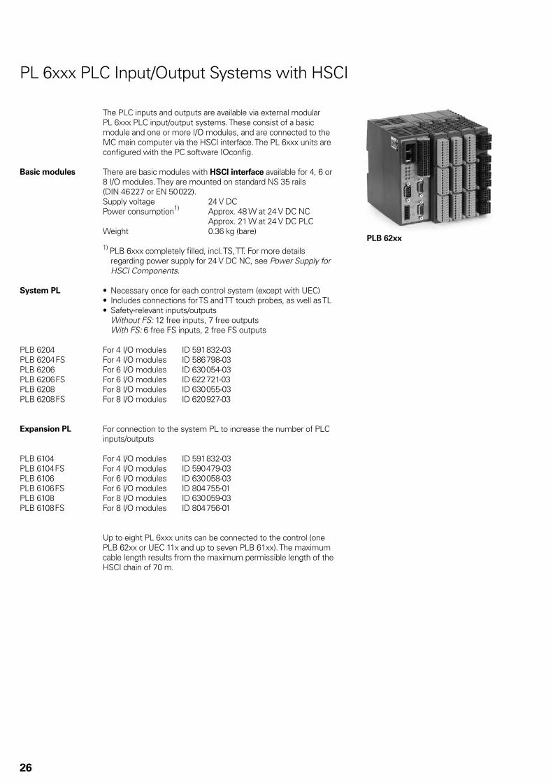
The PLC inputs and outputs are available via external modular PL 6xxx PLC input/output systems. These consist of a basic module and one or more I/O modules, and are connected to the MC main computer via the HSCI interface. The PL 6xxx units are confi gured with the PC software IOconfi g.
Basic modules There are basic modules with HSCI interface available for 4, 6 or 8 I/O modules. They are mounted on standard NS 35 rails (DIN 46 227 or EN 50 022).Supply voltage 24 V DCPower consumption1) Approx. 48 W at 24 V DC NC Approx. 21 W at 24 V DC PLCWeight 0.36 kg (bare)
1) PLB 6xxx completely fi lled, incl. TS, TT. For more details regarding power supply for 24 V DC NC, see Power Supply for HSCI Components.
System PL Necessary once for each control system (except with UEC)• Includes connections for TS and TT touch probes, as well as TL• Safety-relevant inputs/outputs•
Without FS: 12 free inputs, 7 free outputs With FS: 6 free FS inputs, 2 free FS outputs
PLB 6204PLB 6204 FSPLB 6206PLB 6206 FSPLB 6208PLB 6208 FS
For 4 I/O modules ID 591 832-03For 4 I/O modules ID 586 798-03For 6 I/O modules ID 630 054-03For 6 I/O modules ID 622 721-03For 8 I/O modules ID 630 055-03For 8 I/O modules ID 620 927-03
Expansion PL For connection to the system PL to increase the number of PLC inputs/outputs
PLB 6104PLB 6104 FSPLB 6106PLB 6106 FSPLB 6108PLB 6108 FS
For 4 I/O modules ID 591 832-03For 4 I/O modules ID 590 479-03For 6 I/O modules ID 630 058-03For 6 I/O modules ID 804 755-01For 8 I/O modules ID 630 059-03For 8 I/O modules ID 804 756-01
Up to eight PL 6xxx units can be connected to the control (one PLB 62xx or UEC 11x and up to seven PLB 61xx). The maximum cable length results from the maximum permissible length of the HSCI chain of 70 m.
27
I/O modules For HSCI:
There are I/O modules with digital and analog inputs and outputs. For partially occupied basic modules, the unused slots must be occupied by an empty housing.
PLD-H 16-08-00PLD-H 08-16-00PLD-H 08-04-00 FSPLD-H 04-08-00 FS
I/O module with 16 digital inputs and 8 digital outputsI/O module with 8 digital inputs and 16 digital outputsI/O module with 8 digital FS inputs and 4 digital FS outputsI/O module with 4 digital FS inputs and 8 digital FS outputs
Total current Outputs 0 to 7: † 2 A per output († 8 A simultaneously)
Power output Max. 200 WWeight 0.2 kgPLD-H 16-08-00 ID 594 243-02PLD-H 08-16-00 ID 650 891-02PLD-H 08-04-00 FS ID 598 905-02PLD-H 04-08-00 FS ID 727 219-02
PLA-H 08-04-04 Analog module for PL 6xxx with8 analog inputs, ±10 V• 4 analog outputs, ± 10 V• 4 analog inputs for PT 100 thermistors•
Weight 0.2 kgID 675 572-01
Empty housing For unused slots
ID 383 022-11
IOconfi g
(accessory)PC software for confi guring HSCI and PROFIBUS components
PL 550
28
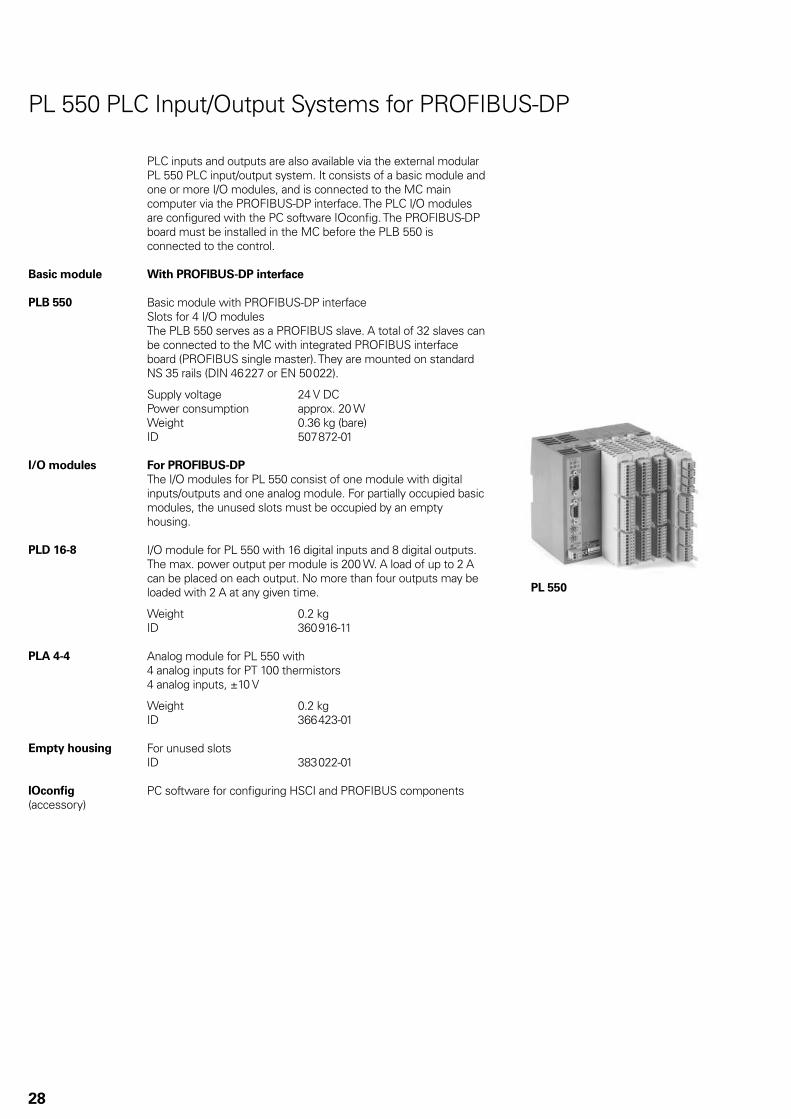
PLC inputs and outputs are also available via the external modular PL 550 PLC input/output system. It consists of a basic module and one or more I/O modules, and is connected to the MC main computer via the PROFIBUS-DP interface. The PLC I/O modules are confi gured with the PC software IOconfi g. The PROFIBUS-DP board must be installed in the MC before the PLB 550 is connected to the control.
Basic module With PROFIBUS-DP interface
PLB 550 Basic module with PROFIBUS-DP interfaceSlots for 4 I/O modulesThe PLB 550 serves as a PROFIBUS slave. A total of 32 slaves can be connected to the MC with integrated PROFIBUS interface board (PROFIBUS single master). They are mounted on standard NS 35 rails (DIN 46 227 or EN 50 022).
Supply voltage 24 V DCPower consumption approx. 20 WWeight 0.36 kg (bare)ID 507 872-01
I/O modules For PROFIBUS-DP
The I/O modules for PL 550 consist of one module with digital inputs/outputs and one analog module. For partially occupied basic modules, the unused slots must be occupied by an empty housing.
PLD 16-8 I/O module for PL 550 with 16 digital inputs and 8 digital outputs.The max. power output per module is 200 W. A load of up to 2 A can be placed on each output. No more than four outputs may be loaded with 2 A at any given time.
Weight 0.2 kgID 360 916-11
PLA 4-4 Analog module for PL 550 with4 analog inputs for PT 100 thermistors4 analog inputs, ±10 V
Weight 0.2 kgID 366 423-01
Empty housing For unused slotsID 383 022-01
IOconfi g
(accessory)PC software for confi guring HSCI and PROFIBUS components
PL 550 PLC Input/Output Systems for PROFIBUS-DP
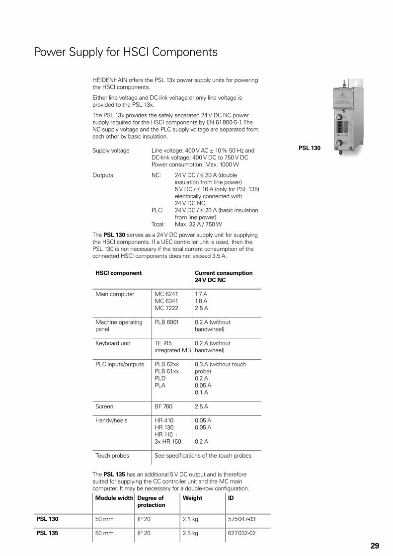
PSL 130
29
Power Supply for HSCI Components
HEIDENHAIN offers the PSL 13x power supply units for powering the HSCI components.
Either line voltage and DC-link voltage or only line voltage is provided to the PSL 13x.
The PSL 13x provides the safely separated 24 V DC NC power supply required for the HSCI components by EN 61 800-5-1. The NC supply voltage and the PLC supply voltage are separated from each other by basic insulation.
Supply voltage Line voltage: 400 V AC ± 10 % 50 Hz and DC-link voltage: 400 V DC to 750 V DC Power consumption: Max. 1000 W
Outputs NC: 24 V DC / † 20 A (double insulation from line power)
5 V DC / † 16 A (only for PSL 135) electrically connected with 24 V DC NC
PLC: 24 V DC / † 20 A (basic insulation from line power)
Total: Max. 32 A / 750 W
The PSL 130 serves as a 24 V DC power supply unit for supplying the HSCI components. If a UEC controller unit is used, then the PSL 130 is not necessary if the total current consumption of the connected HSCI components does not exceed 3.5 A.
HSCI component Current consumption
24 V DC NC
Main computer MC 6241MC 6341MC 7222
1.7 A1.8 A2.5 A
Machine operating panel
PLB 6001 0.2 A (without handwheel)
Keyboard unit TE 745integrated MB
0.2 A (without handwheel)
PLC inputs/outputs PLB 62xxPLB 61xxPLDPLA
0.3 A (without touch probe)0.2 A0.05 A0.1 A
Screen BF 760 2.5 A
Handwheels HR 410HR 130HR 110 +3x HR 150
0.05 A0.05 A
0.2 A
Touch probes See specifi cations of the touch probes
The PSL 135 has an additional 5 V DC output and is therefore suited for supplying the CC controller unit and the MC main computer. It may be necessary for a double-row confi guration.
Module width Degree of
protection
Weight ID
PSL 130 50 mm IP 20 2.1 kg 575 047-03
PSL 135 50 mm IP 20 2.5 kg 627 032-02

30
HR 130 Panel-mounted handwheel with ergonomic control knob.It is connected to the PLB 6001 or TE 745 directly or via extension cable.
Weight Approx. 0.7 kg
HR 130 without detent ID 540 940-03HR 130 with detent ID 540 940-01
Accessories
Electronic Handwheels
Support of electronic handwheels is standard on the TNC 640. The following handwheels can be installed:
One • HR 410 portable handwheel, orOne • HR 130 panel-mounted handwheel, orUp to three • HR 150 panel-mounted handwheels via HRA 110 handwheel adapter
Handwheels are connected to the MB machine operating panel or the PLB 6001 adapter for HSCI.
HR 410 Portable electronic handwheel withKeys for the selection of 5 axes• Traverse direction keys• Keys for three preset feed rates• Actual-position-capture key• Three keys with machine functions (see below)• Two permissive buttons (24 V)• Emergency stop button (24 V)• Magnetic holding pads•
All keys are designed as snap-on keys and can be replaced by keys with other symbols. (For key symbols see Snap-On Keys.)
Weight Approx. 1 kg
Without detent With detent Keys
HR 410 ID 296 469-53 – FCT A, FCT B, FCT C
ID 296 469-54 – Spindle right/left/stop
ID 296 469-55 ID 535 220-05 NC start/stop, spindle start (for PLC basic program)
HR 410 FS ID 337 159-11 ID 578 114-03 FCT A, FCT B, FCT C

31
HRA 110 Handwheel adapter for connection of up to three HR 150 panel-mounted handwheels and two switches for axis selection and for selecting the interpolation factor. The fi rst two handwheels are permanently assigned to axes 1 and 2. The third handwheel is assigned to the axes over a step switch (accessory) or by machine parameters. The position of the second step switch (accessory) is evaluated by the PLC, for example to set the proper interpolation.
HRA 110
ID 261 097-04Weight Approx. 1.5 kg
Handwheel step switch with knob and cableID 270 908-xx
HR 150 Panel-mounted handwheel with ergonomic control knob for connection to the HRA 110 handwheel adapter.
Weight Approx. 0.7 kgHR 150 without detent ID 540 940-07HR 150 with detent ID 540 940-06

32
The PLB 6001 HSCI adapter is required in order to connect an OEM-specifi c machine operating panel to the TNC 640. The spindle-speed and feed-rate override potentiometers of the TE 7xx and the HR handwheel are also connected to this adapter.
PLB 6001 HSCI interface• Connection for HR handwheel• Connection for spindle-speed, feed-rate and rapid-traverse • overrideScrew fastening or top-hat-rail mounting• Confi guration of the PLC inputs/outputs with the IOconfi g • computer softwareInputs and outputs for keys and key illumination•
Without FS: terminals for 64 inputs and 32 outputs With FS: terminals for 32 FS inputs and 32 outputs
Weight Approx. 1.2 kgPLB 6001: ID 668 792-01PLB 6001 FS: ID 722 083-01
HSCI Adapter for OEM Machine Operating Panel
Digital drive designs sometimes also require analog axes or spindles. The additional module CMA-H 04-04-00 (Controller Module Analog – HSCI) makes it possible to integrate analog servo drives in an HSCI system. However, all of the interpolating axes must be either analog or digital. Mixed operation is not possible.
The CMA-H is connected to the HSCI control system through a slot on the underside of the CC or UEC. Every controller unit has slots for two boards. The CMA-H does not increase the total number of available axes: every analog axis used reduces the number of available digital control loops by one. Analog control loops also need to be enabled on the SIK. The analog control-loop outputs can only be accessed via the NC, and not via the PLC.
CMA-H 04-04-00 Additional module for analog axes/spindlesExpansion board for CC 61xx or UEC 11x controller units• 4 analog outputs ± 10 V for axes/spindle• Spring-type plug-in terminals•
ID 688 721-01
Module for Analog Axes
����������
�����������
����������
����������
����������
����������
����������
����������
���������
�����������
�����������
�����������
�����������
����������
����������
����������
����������
��������� �
��������� �
��������� �
�����������
�����������
�����������
�����������
����������
����������
����������
�����������
�����������
�����������
�����������
����������
����������
�
�
����������
����������
����������
�����������
�����������
�����������
�����������
�����������
�����������
����������
����������
�����������
���������
���������
����������
����������
33
Snap-On Keys For Control
Axis keys
Orange
Spindle functions
Other keys
Gray
Machine functions
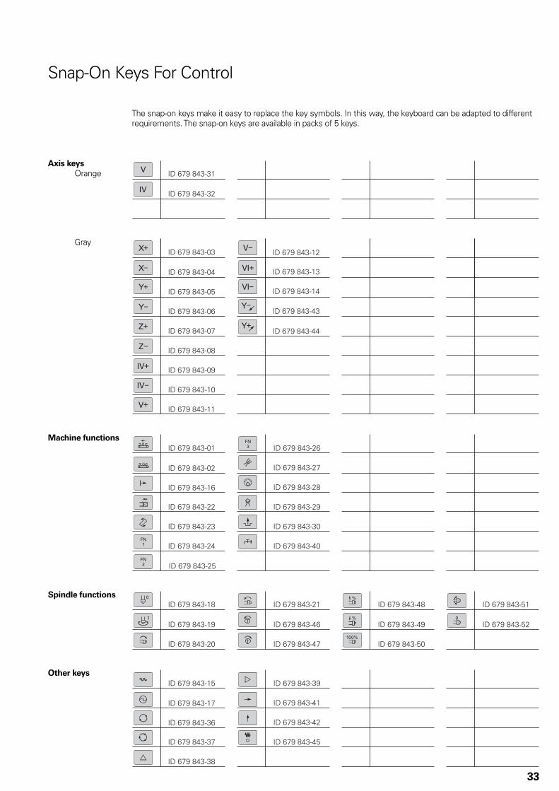
The snap-on keys make it easy to replace the key symbols. In this way, the keyboard can be adapted to different requirements. The snap-on keys are available in packs of 5 keys.
����������
����������
���������� ����������
�����������
���������� ���������
����������
���������
����������
�����������
�����������
�����������
�����������
�����������
����������
�����������
�����������
�����������
������������
�����������
�����������
�����������
�����������
�����������
�����������
�����������
�����������
�����������
�����������
�����������
�����������
�����������
�����������
����������
����������
�����������
�����������
�����������
�����������
�����������
����������
�����������
�����������
������������
�
�����������
�����������
�����������
�����������
�����������
����������
����������
����������
����������
���������� ����������
�����������
����������
�����������
�����������
�����������
�����������
�����������
����������
����������
�����������
�����������
����������!
�����������
�����������
����������
����������"
����������
����������
�����������
����������� ����������
��������������������
����������
����������
���� � �� �
�����������
�����������
����������
��������� �
�����������
�����������
���������
���������
�����������
�����������
���������
�����������
�����������
�����������
����������"
�����������
����������
�
����������
����������
����������
34
Snap-on keys for HR 410
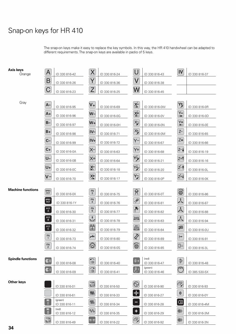
The snap-on keys make it easy to replace the key symbols. In this way, the HR 410 handwheel can be adapted to different requirements. The snap-on keys are available in packs of 5 keys.
Axis keys
Orange
Spindle functions
Other keys
Gray
(green)
(red)
(red)
(green)
Machine functions
TS 220
TT 140
TS 220
TT 140
TL Micro 150,
TL Micro 300
35
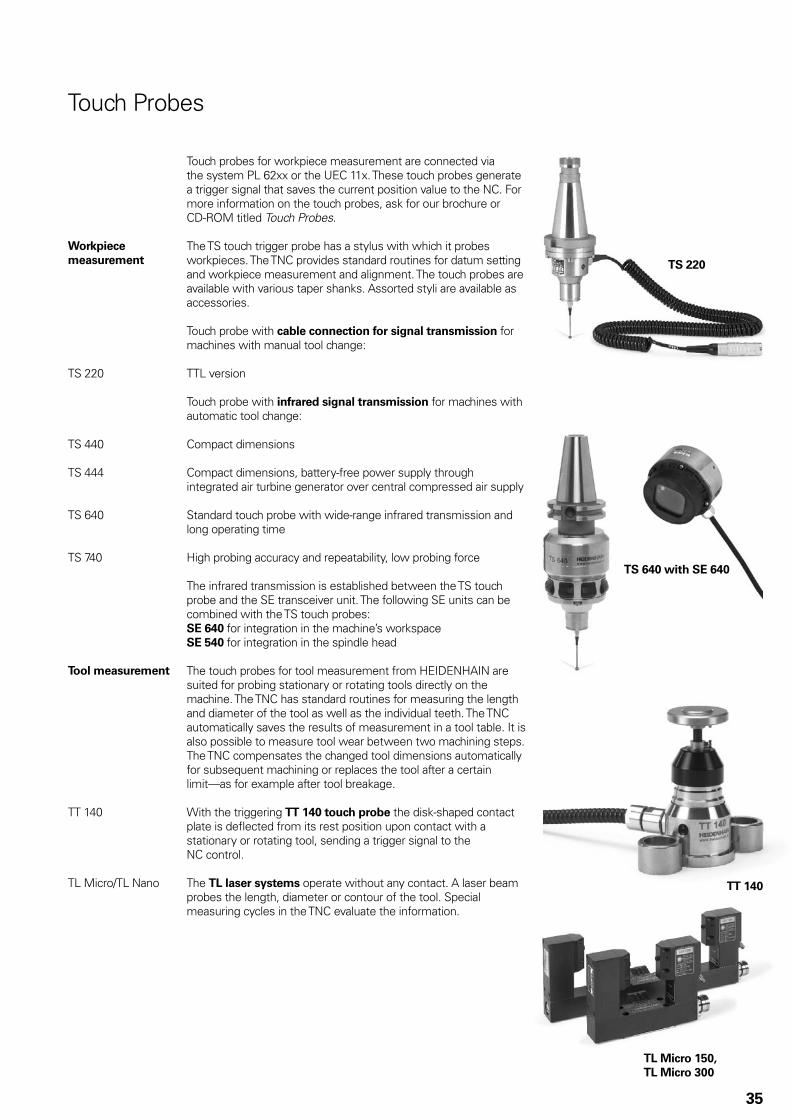
Touch Probes
Touch probes for workpiece measurement are connected via the system PL 62xx or the UEC 11x. These touch probes generate a trigger signal that saves the current position value to the NC. For more information on the touch probes, ask for our brochure or CD-ROM titled Touch Probes.
Workpiece
measurement
The TS touch trigger probe has a stylus with which it probes workpieces. The TNC provides standard routines for datum setting and workpiece measurement and alignment. The touch probes are available with various taper shanks. Assorted styli are available as accessories.
Touch probe with cable connection for signal transmission for machines with manual tool change:
TS 220 TTL version
Touch probe with infrared signal transmission for machines with automatic tool change:
TS 440 Compact dimensions
TS 444 Compact dimensions, battery-free power supply through integrated air turbine generator over central compressed air supply
TS 640 Standard touch probe with wide-range infrared transmission and long operating time
TS 740 High probing accuracy and repeatability, low probing force
The infrared transmission is established between the TS touch probe and the SE transceiver unit. The following SE units can be combined with the TS touch probes:SE 640 for integration in the machine’s workspaceSE 540 for integration in the spindle head
Tool measurement The touch probes for tool measurement from HEIDENHAIN are suited for probing stationary or rotating tools directly on the machine. The TNC has standard routines for measuring the length and diameter of the tool as well as the individual teeth. The TNC automatically saves the results of measurement in a tool table. It is also possible to measure tool wear between two machining steps. The TNC compensates the changed tool dimensions automatically for subsequent machining or replaces the tool after a certain limit—as for example after tool breakage.
TT 140 With the triggering TT 140 touch probe the disk-shaped contact plate is defl ected from its rest position upon contact with a stationary or rotating tool, sending a trigger signal to the NC control.
TL Micro/TL Nano The TL laser systems operate without any contact. A laser beam probes the length, diameter or contour of the tool. Special measuring cycles in the TNC evaluate the information.
TS 640 with SE 640

������ ��������������� �����
����
���
�
��
����
����
����
���������
���������������� �����
���������
����� �����
���������
����� �����
���
���
����������
����������
���
���
����������
��������
� ��
!������
���������
���
����������
����
"#�
������������
!�����
� ��
!������
���������
�
���������
��������
"#�
$% &
���
�!�����
���
��������
�
���������
���
�
����������
����������
��
��
��' (����
' (����
' (����
��
����
���
���
�)& *
����
)& *
+ �����
��
��
���
�
���������
�
�������������!������
����������
����
���
�
����������
����
' (����
' (����
' (����
��������������!�����
��
���
�������������!������
����������
����������
��������������!������
�� ��
��
��
��
��
��
��
��
��
���������� &
�����
���������� $
,� -�����
���������� -����
�!������
�!������
�!������
����������
)& *
����������
����������
�!������
�&$
)& *
����������
����
��������
.��
��������
)& *
� ����
�&$���������������
�&$���������������
�!�����
�!������
�&$���������������
�&$���������������
�!�����
����
�!������
���������
��
��
�&$
������
������
���
���
��������
��
��
�����
���++
+����������
����
���++
���++
&�//0�������
��1!��������
�/23!4/
5�/��6�����07/8
5�/�8����
5�/�8����
��7�!9
/�4���2�77/2����
����������
��7�!9
/�4���2�77/2����
����������
���++
���++
��7�!9
/�4���2�77/2����
����������
5�/��6�����07/8
:�7;�3�2�4���/4������3��</�"#�
50!�
�/2�4���/4��2���������
3�2�����07/��3��/4/��!2;�
� 8����/�
�����4!=
7/�������>�3�2��/�!2!������������?��<�4���/4���9�4!=
7/�������>�3�2�/��/�0��9�/������9�4���/4���9�4!=
7/
@����
47�0/0
�?��<��</�$-����
@@����47�0/0
�?��<��</�.$�����
�
)& *����!7�7/�
9�<�����
�7/4�2�4!7�4!=
��/�
'�==���4!=
7/�3�2���3��A/;��@�
��1!��?
��<���
42/�
/��!7���9�!7�
+�2/7;��/2�!7��
�1!�����
'�==���4!=
7/�3�2�����
'�==���4!=
7/�3�2���3��A/;��@�
@@�
36
Cable Overviews
Control System with UEC 11x

���
���5������
��5
���$������
��$@�
����5
������
��5
����$
������
���$
@�
���
����������
����������
���
���
����������
��������
� ��
!������
���������
���
����������
����
"#�
������������
!�����
� ��
!������
���������
�
���������
��������
"#�
$% &
���
�!�����
)& *
����������
����������
�!������
���
��������
�
���������
���
�
����������
����������
��
��
��' (����
' (����
' (����
��
���
�5
���
���
���
�
����5
)& *
���
�$@@@�
����$
@@@�
����
)& *
+B.
���
����
���
�
+ �����
+ �����
��
��
�&$
)& *
����������
���
�
����
��������
.��
��������
)& *
� ����
�&$
������
�&$���������������
�&$���������������
�!�����
�!������
�&$���������������
�&$���������������
�!�����
�!������
���������� &
�����
���������� $
,� -�����
���������� -����
�!������
�!������
�!������
�������������!������
����������
����
���
�
����������
����
' (����
' (����
' (����
��������������!�����
��
���
�������������!������
����������
����������
��������������!������
�� ��
��
��
��
��
��
��
��
��
���5�����5
���$������$@
������
����������
����
���
���
��������
���������
��
��
��
��
�����
���++
+����������
����
���++
���++
&�//0�������
��1!��������
�/23!4/
5�/��6�����07/8
5�/�8����
5�/�8����
��7�!9
/�4���2�77/2����
����������
��7�!9
/�4���2�77/2����
����������
���++
���++
��7�!9
/�4���2�77/2����
����������
5�/��6�����07/8
��7;�3�2�4���/4������3��</�"#�
50!�
�/2�4���/4��2���������
3�2�����07/��3��/4/��!2;�
@@@�� ��?��<���0�4���2�77/2�=�!20
��1!��?
��<���
42/�
/��!7���9�!7�
+�2/7;��/2�!7��
�1!�����
� 8����/�
�����4!=
7/�������>�3�2��/�!2!������������?��<�4���/4���9�4!=
7/�������>�3�2�/��/�0��9�/������9�4���/4���9�4!=
7/
@����
47�0/0
�?��<��</�$-����
@@����47�0/0
�?��<��</�.$�����
�
)& *����!7�7/�
9�<�����
'�==���4!=
7/�3�2�����@@�
�7/4�2�4!7�4!=
��/�
'�==���4!=
7/�3�2���3��A/;��@�
'�==���4!=
7/�3�2���3��A/;��@�
37
Control System with CC 6106

��
��
�����
������
���
����
������������
�����������������
���������������
����������
����������
"1'����
���
���
��
��
�� �� �
�� �� �
�� �� �
������
����
��
���
������
���
+B����
���������
�����������������
����������
����������
���
���
���������������
��
��
��
���
��
����
��
����
��
����
��
���
+B����
������������
�����������������
���������������
����������
����������
���
�����
��
��
��
���
��
����
��
����
��
����
���
���
� ��
���
���
����������
����������
���������
�������������������
���
���
�����������������
"1'����
���
�����
��
��
��
��
��
�� �� �
������
���
+B����
������
��
��
����
�����
�����
�����
�����
������
��
��
������
��
��
������
��
��
������
#<2//��<
!�/
!4�4!�
!4���
2��������� �
�/�3�7�/2
�+ :&���
��/�3�7�/2
�+ :&����5
#<2//��<
!�/
!4�4!�
!4���
2���������
��� !"#�$%&'(#'(�)%�%('*'%'(!#$&'+
�3��//0/0
�
��� !"#�$%&'(#'(�)('*'%'(!#$&'+
&//�.
���2��4!�!7�9
3�2���?/2�4!=
7/�����
���2
&//�.
���2��4!�!7�9
3�2���?/2�4!=
7/�����
���2
�3��//0/0
�
&//�.
���2��4!�!7�9
3�2���?/2�4!=
7/�����
���2
��,-.!(�$%&'(#'(�)%�%('*'%'(!#$&'+
��,-.!(�$%&'(#'(�)('*'%'(!#$&'+
&//�.
���2��4!�!7�9
3�2���?/2�4!=
7/�����
���2
�3��//0/0
�
�3��//0/0
�
�3��//0/0
�
�3��//0/0
�
&//�.
���2��4!�!7�9
3�2���?/2�4!=
7/�����
���2
38
Inverter Systems

����������
������
���������
���
+
����������
���
##����
����������
���
#&����
���������
����������
����������
���
��������
���������
���������
���
���
��
���������
���
���
���������
����������
���
����
+ ����
����
���%'&�����
����������
����������
����
:������
����������
���
��</2�/�
���������
����������
����
����
���������
� �
�����
����������
#&���
����������
&����
����������
#&��
������
����
&����
����������
# �(!�
������������
# �.�42����������������
# �.�42�����
������������
# �.�42�����
������������
����������
&����
����������
���
��
�����
#&���
����������
����������
����
������
.5�)�������
���
�!�������
�
���������
���������
����������
)'5����
����������
���
����������
���������
����������
��
)'����
��������
����������������)'����
��������
����������������)'���
���������
����������
50!�
�/2�������
����������
� 8����/�
�����4!=
7/�������>�3�2��/�!2!������������?��<�4���/4���9�4!=
7/�������>�3�2�/��/�0��9�/������9�4���/4���9�4!=
7/
50!�
�/2������
����������
���/4��2�<�����9��
����=/������/0
�&$�<�=
���������
+�'��2��/4��C/�!2��2
&�//7�=2!�0��9
?��<�4���/4������3�!��&$�<�=
B��<�( ���3�?!2/�����������3�2�#
( ����8
��7;�#&����%�����##��
!�!7�9�!���
�����
����
39
Accessories

40
Technical Description
Axes
Linear axes Depending on the options enabled, the TNC 640 can control linear axes with any axis designation (X, Y, Z, U, V, W ...).
Display and programming
–99 999.999 to +99 999.999 [mm]–99 999.999 99 to +99 999.999 99 [mm] with option 23
Feed rate in mm/min relative to the workpiece contour, or mm per spindle revolution
Feed rate override: 0 to 150 %
Traverse range –99 999.999 to +99 999.999 [mm]–99 999.999 99 to +99 999.999 99 [mm] with option 23
The machine tool builder defi nes the traverse range.The user can set additional limits to the traverse range if he wishes to reduce the working space.Various traverse ranges can be defi ned per axis using parameter sets (selection by PLC).
Rotary axes The TNC 640 can control rotary axes with any axis designation (A, B, C, U ...).
Special parameters and PLC functions are available for rotary axes with Hirth coupling.
Display and programming
0° to 360° or–99 999.999 to +99 999.999 [°]–99 999.999 99 to +99 999.999 99 [°] with option 23
Feed rate in degrees per minute (°/min)
Traverse range –99 999.999 to +99 999.999 [°]–99 999.999 99 to +99 999.999 99 [°] with option 23
The machine tool builder defi nes the traverse range.The user can set additional limits to the traverse range if he wishes to reduce the working space.Various traverse ranges can be defi ned per axis using parameter sets (selection by PLC).
Free rotation For milling-turning operations, the rotary axis can be started via the PLC with a defi ned feed rate. For functions specifi c to milling/turning machines, see Turning Operations.
Cylindrical surface
interpolation
(option 8)
A contour defi ned in the working plane is machined on a cylindrical surface.
Axis clamping The control loop can be opened through the PLC in order to clamp specifi c axes.
�
�
�
41
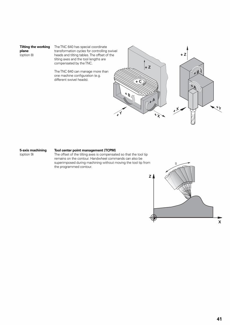
Tilting the working
plane
(option 8)
The TNC 640 has special coordinate transformation cycles for controlling swivel heads and tilting tables. The offset of the tilting axes and the tool lengths are compensated by the TNC.
The TNC 640 can manage more than one machine confi guration (e.g. different swivel heads).
5-axis machining
(option 9)Tool center point management (TCPM)
The offset of the tilting axes is compensated so that the tool tip remains on the contour. Handwheel commands can also be superimposed during machining without moving the tool tip from the programmed contour.

���
���
��
��
���
���
��
��
42
Synchronized axes Synchronous axes are moved simultaneously and are programmed with the same axis designation, e.g. gantry axes, tandem tables or torque control.
Gantry axes Gantry axes can be distributed to several drive-control motherboards (DSP), and so to several controller units.
Torque control Torque control is used on machines with mechanically coupled motors for which
a defi ned distribution of drive torque is • desired,
orparts of the controlled system show • a backlash effect that can be eliminated by “tensioning” the servo drives (e.g. racks).
For torque control, the master and slave must be on the same motherboard (DSP).
Depending on the controller unit being used, up to fi ve slave axes can be confi gured for each master in this manner.
PLC axes Axes can be controlled by the PLC. They are programmed over M functions or OEM cycles.
The PLC axes are positioned independently of the NC axes and are therefore designated as asynchronous axes.

�
�
/0
/1
/2
/�
/3
/0
/1
/2
�
�4����4���������4
�4����4����������
�
/3
43
Turning Operations
Performing turning
operations
(option 50)
The TNC 640 supports machines that can perform a combination of milling and turning operations in a single setup. It offers the operator a comprehensive package of cycles for both types of operations, which are programmed in HEIDENHAIN’s workshop-oriented conversational format.
In turning mode, the rotary table serves as the lathe spindle, while the milling spindle with the tool remains stationary.
Rotationally symmetric contours are produced during turning operations. The preset must be in the center of the lathe spindle for this.
Machines for milling and turning must fulfi ll special demands. A basic prerequisite is a machine designed with high rigidity, in order to ensure a low oscillation tendency even when the machine table (acting as lathe spindle) is turning at high speeds.
Toggling between
milling and turning
modes
When switching between turning and milling modes, the TNC switches the diameter programming on or off, respectively, selects the XZ plane as working plane for turning, and shows whether it is in milling or turning mode in the status display.
The machine operator uses the NC commands FUNCTION MODE TURN and FUNCTION MODE MILL to toggle between milling and turning modes. The machine-specifi c procedures necessary here are realized via OEM macros. In these macros the machine tool builder specifi es, for example, which kinematics model is active for the milling or turning mode, and which axis and spindle parameters are in effect. Since the FUNCTION MODE TURN and FUNCTION MODE MILL commands are independent of the type of machine, NC programs can be exchanged between different types of machines.
Machine in turning modeMachine in milling mode

44
Measuring the
unbalance –
Balancing
An important and basic prerequisite for turning operations is that the radial runout of the workpiece has been balanced. Both the machine (rotary table) and the workpiece must be balanced before machining. If the clamped workpiece has an unbalance, undesirable centrifugal forces can result, infl uencing the accuracy of the runout.
An unbalance of the rotary table can endanger the machine operator, as well as lower the quality of the workpiece and reduce the machine’s lifetime.
The TNC 640 can determine an unbalance of the rotary table by measuring the effects of the centrifugal forces on neighboring axes. A rotary table positioned via a linear axis would be ideal for this. For other machine designs, measurement of the unbalance via external sensors is appropriate.
The TNC 640 offers the following functions:Calibration of the unbalance•
A calibration cycle ascertains the unbalance behavior of the rotary table. This unbalance calibration is generally performed by the machine tool builder before he ships the machine. During execution of the calibration cycle, the TNC generates a table describing the unbalance behavior of the rotary table.
Balancing•
After the workpiece blank to be turned has been clamped, the machine operator can use a measuring cycle to determine the current unbalance. During balancing, the TNC assists the machine operator by indicating the mass and position of the balancing weights.
Unbalance monitoring•
The TNC constantly monitors the momentary unbalance during machining. An NC stop is triggered if a specifi ed limit value is exceeded.

45
Spindle
The TNC 640 contouring control is used in connection with the HEIDENHAIN inverter systems with fi eld-oriented control. As an alternative, an analog nominal value can be output.
Controller unit
CC 61xx
With the CC 61xx and UEC controller units, the PWM basic frequency can be set for each controller assembly (e.g. 4 kHz). Possible basic frequencies are 3.33 kHz, 4 kHz or 5 kHz. The Double Speed option (option 49) can double this frequency for high-speed spindles (e.g. 8 kHz for HF spindles) (see the TNC 640 Technical Manual).
Controller groups 1: X51 + X522: X53 + X543: X55 + X56
Maximum spindle
speed
The maximum spindle speed is calculated as follows:
nmax =
fPWM = PWM frequency in HzNPP = Number of pole pairs
Operating-mode
switchover
Various parameter sets can be stored for controlling the spindle (e.g. for wye/delta connection). You can switch between the parameter sets in the PLC.
Position-controlled
spindle
The position of the spindle is monitored by the TNC 640.
Encoder HEIDENHAIN rotary encoder with sinusoidal voltage signals (1 VPP) or EnDat interface.
Tapping There are special cycles for tapping with or without fl oating tap holder. For tapping without fl oating tap holder, the spindle must be operated under position control.
Oriented spindle
stop
With a position-controlled spindle, the spindle can be positioned exactly to 0.1°.
Spindle override 0 to 150 %
Gear ranges A specifi c nominal speed can be defi ned for each gear range. The gear code is output via the PLC.
Second spindle Up to two spindles can be alternately controlled.You can switch from spindle 1 to spindle 2 through the PLC. Because the second spindle is controlled instead of an axis, the number of available axes is reduced by one.
fPWM · 60 000 min–1
NPP · 5000 Hz
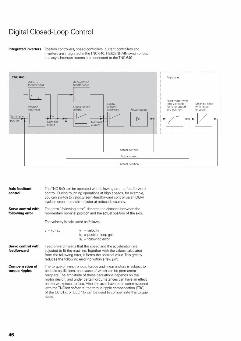
������������� �!�������"���#��"
���#��!$%���%#" �"�
&����'#!#"� �!�"#!�"$����#��"%#"�"#!#"��(�������(#��!�#�
�������
�# �"��!�)���)�!����(����#�!"#�
�#��!�#��#�!"#���"
�#'�����(���
�#'�����*""��!
������"�!�#�%���%#" �"�
�#'����(#��!�#�
��)�!���*""��!�#�!"#���"
��!*����*""��!
��!*���(#��!�#�
��!*����(���
TNC 640
46
Digital Closed-Loop Control
Integrated inverters Position controllers, speed controllers, current controllers and inverters are integrated in the TNC 640. HEIDENHAIN synchronous and asynchronous motors are connected to the TNC 640.
Axis feedback
control
The TNC 640 can be operated with following error or feedforward control. During roughing operations at high speeds, for example, you can switch to velocity semi-feedforward control via an OEM cycle in order to machine faster at reduced accuracy.
Servo control with
following error
The term “following error” denotes the distance between the momentary nominal position and the actual position of the axis.
The velocity is calculated as follows:
v = kv · sa v = velocity kv = position loop gain sa = following error
Servo control with
feedforward
Feedforward means that the speed and the acceleration are adjusted to fi t the machine. Together with the values calculated from the following error, it forms the nominal value. This greatly reduces the following error (to within a few µm).
Compensation of
torque ripples
The torque of synchronous, torque and linear motors is subject to periodic oscillations, one cause of which can be permanent magnets. The amplitude of these oscillations depends on the motor design, and under certain circumstances can have an effect on the workpiece surface. After the axes have been commissioned with the TNCopt software, the torque ripple compensation (TRC) of the CC 61xx or UEC 11x can be used to compensate this torque ripple.

&
!
5
#
#
#
47
Control-loop cycle
times
The cycle time for path interpolation is defi ned as the time interval during which interpolation points on the path are calculated. The cycle time for fi ne interpolation is defi ned as the time interval during which interpolation points are calculated that lie between the interpolation points calculated for path interpolation. The cycle time for the position controller is defi ned as the time interval during which the actual position value is compared to the calculated nominal position value. The cycle time for the speed controller is defi ned as the time interval during which the actual speed value is compared to the calculated nominal speed value. The cycle time for the current controller is defi ned as the time interval during which the actual current value is compared to the calculated nominal current value.
TimePo
sitio
n
CC 6xxx/UEC 11x
Path interpolation 3 ms
Fine interpolation 0.2 ms/0.1 ms1)
Position controller 0.2 ms/0.1 ms2)
Speed controller 0.2 ms/0.1 ms1)
Current controller 0.1 ms at fPWM = 5000 Hz
1) Double-speed (with option 49) without position encoder2) Single-speed/double-speed (with option 49)
Double-speed
control loops
(option 49)
Double-speed control loops permit higher PWM frequencies as well as shorter cycle times of the speed controller. This makes improved current control for spindles possible, and also higher control performance for linear and torque motors.
Jerk The derivative of acceleration is referred to as jerk. A linear change in acceleration causes a jerk step. Such motion sequences may cause the machine to oscillate.
Jerk limiting To prevent machine oscillations, the jerk is limited to attain optimum path control.
Smoothed jerk The jerk is smoothed by nominal position value fi lters. The TNC 640 therefore mills smooth surfaces at the highest possible feed rate and yet keeps the contour accurate. The operator programs the permissible tolerance in a cycle.Special fi lters for HSC machining (HSC fi lters) can specifi cally suppress the natural frequencies of an individual machine. The desired accuracy is attained with the very high surface quality.
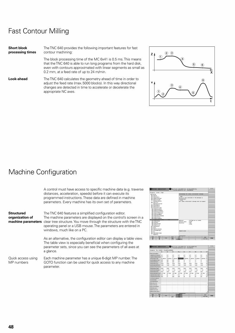
48
Machine Confi guration
A control must have access to specifi c machine data (e.g. traverse distances, acceleration, speeds) before it can execute its programmed instructions. These data are defi ned in machine parameters. Every machine has its own set of parameters.
Structured
organization of
machine parameters
The TNC 640 features a simplifi ed confi guration editor.The machine parameters are displayed on the control’s screen in a clear tree structure. You move through the structure with the TNC operating panel or a USB mouse. The parameters are entered in windows, much like on a PC.
As an alternative, the confi guration editor can display a table view. The table view is especially benefi cial when confi guring the parameter sets, since you can see the parameters of all axes at a glance.
Quick access using MP numbers
Each machine parameter has a unique 6-digit MP number. The GOTO function can be used for quick access to any machine parameter.
Short block
processing times
The TNC 640 provides the following important features for fast contour machining:
The block processing time of the MC 6x41 is 0.5 ms. This means that the TNC 640 is able to run long programs from the hard disk, even with contours approximated with linear segments as small as 0.2 mm, at a feed rate of up to 24 m/min.
Look-ahead The TNC 640 calculates the geometry ahead of time in order to adjust the feed rate (max. 5000 blocks). In this way directional changes are detected in time to accelerate or decelerate the appropriate NC axes.
Fast Contour Milling
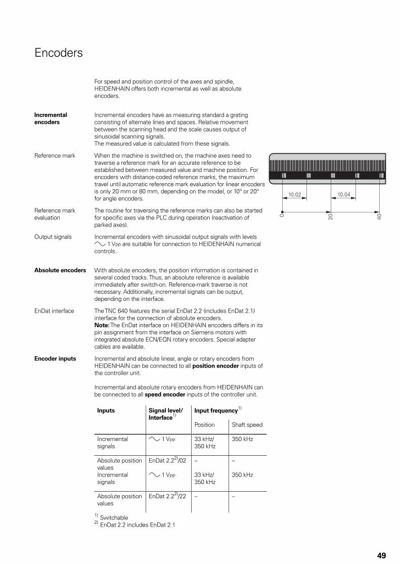
49
Encoders
For speed and position control of the axes and spindle, HEIDENHAIN offers both incremental as well as absolute encoders.
Incremental
encoders
Incremental encoders have as measuring standard a grating consisting of alternate lines and spaces. Relative movement between the scanning head and the scale causes output of sinusoidal scanning signals.The measured value is calculated from these signals.
Reference mark When the machine is switched on, the machine axes need to traverse a reference mark for an accurate reference to be established between measured value and machine position. For encoders with distance-coded reference marks, the maximum travel until automatic reference mark evaluation for linear encoders is only 20 mm or 80 mm, depending on the model, or 10° or 20° for angle encoders.
Reference mark evaluation
The routine for traversing the reference marks can also be started for specifi c axes via the PLC during operation (reactivation of parked axes).
Output signals Incremental encoders with sinusoidal output signals with levels » 1 VPP are suitable for connection to HEIDENHAIN numerical controls.
Absolute encoders With absolute encoders, the position information is contained in several coded tracks. Thus, an absolute reference is available immediately after switch-on. Reference-mark traverse is not necessary. Additionally, incremental signals can be output, depending on the interface.
EnDat interface The TNC 640 features the serial EnDat 2.2 (includes EnDat 2.1) interface for the connection of absolute encoders.Note: The EnDat interface on HEIDENHAIN encoders differs in its pin assignment from the interface on Siemens motors with integrated absolute ECN/EQN rotary encoders. Special adapter cables are available.
Encoder inputs Incremental and absolute linear, angle or rotary encoders from HEIDENHAIN can be connected to all position encoder inputs of the controller unit.
Incremental and absolute rotary encoders from HEIDENHAIN can be connected to all speed encoder inputs of the controller unit.
Inputs Signal level/
Interface1)
Input frequency1)
Position Shaft speed
Incremental signals
» 1 VPP 33 kHz/350 kHz
350 kHz
Absolute position valuesIncremental signals
EnDat 2.22)/02
» 1 VPP
–
33 kHz/350 kHz
–
350 kHz
Absolute position values
EnDat 2.22)/22 – –
1) Switchable2) EnDat 2.2 includes EnDat 2.1

50
The TNC 640 automatically compensates mechanical errors on the machine.
Linear error Linear error can be compensated over the entire travel range for each axis.
Nonlinear error The TNC 640 can compensate for ball-screw pitch errors and sag errors simultaneously. The compensation values are stored in a table.
Backlash The play between table movement and rotary encoder movement on direction changes can be compensated in length measurements by spindle and rotary encoder. This backlash is outside the controlled system.
Hysteresis The hysteresis between table movement and motor movement is also compensated in length measurements. In this case the hysteresis is within the controlled system.
Reversal peaks In circular movements, reversal peaks can occur at quadrant transitions due to mechanical infl uences. The TNC 640 can compensate for these reversal peaks.
Stick-slip friction At very low feed rates, high static friction can cause the slide to stop and start repeatedly for short periods. This is commonly known as stick-slip. The TNC 640 can compensate for this problem condition.
Sliding friction Sliding friction is compensated by the speed controller of the TNC 640.
Thermal expansion To compensate thermal expansion, the machine’s expansion behavior must be known.
The temperature can be recorded via thermistors connected to the analog inputs of the TNC 640. The PLC evaluates the temperature information and transfers the compensation value to the NC.
Types of Error Compensation

51
KinematicsOpt
(option 48)Using the KinematicsOpt function, machine tool builders and end users can check the accuracy of rotary or swivel axes, and compensate for possible displacements of the center of rotation of these axes. The deviations are automatically transferred to the kinematics description and can be taken into account in the kinematics calculation.
In order to measure the rotary axes, you must attach a calibration sphere (e.g. KKH 100 or KKH 250 from HEIDENHAIN) at any position on the machine table. A HEIDENHAIN touch probe uses a special cycle to probe this calibration sphere, and measures the rotary axes of the machine fully automatically. But fi rst you defi ne the resolution of the measurement and defi ne for each rotary axis the range that you want to measure. The results of measurement are the same regardless of whether the axis is a rotary table, a tilting table or a swivel head.
Calibration sphere
(accessory)HEIDENHAIN offers calibration spheres as accessories for the measurement of rotary axes with KinematicsOpt:KKH 100 Height 100 mm ID 655 475-02KKH 250 Height 250 mm ID 655 475-01
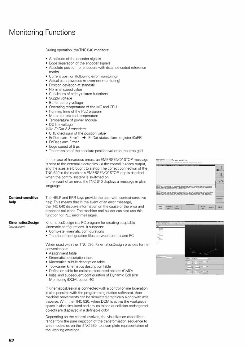
52
Monitoring Functions
During operation, the TNC 640 monitors:
Amplitude of the encoder signals• Edge separation of the encoder signals• Absolute position for encoders with distance-coded reference • marksCurrent position (following error monitoring)• Actual path traversed (movement monitoring)• Position deviation at standstill• Nominal speed value• Checksum of safety-related functions• Supply voltage• Buffer battery voltage• Operating temperature of the MC and CPU• Running time of the PLC program• Motor current and temperature• Temperature of power module• DC-link voltage•
With EnDat 2.2 encoders:CRC checksum of the position value• EnDat alarm Error1 • EnDat status alarm register (0xEE)EnDat alarm Error2• Edge speed of 5 µs• Transmission of the absolute position value on the time grid•
In the case of hazardous errors, an EMERGENCY STOP message is sent to the external electronics via the control-is-ready output, and the axes are brought to a stop. The correct connection of the TNC 640 in the machine’s EMERGENCY STOP loop is checked when the control system is switched on.In the event of an error, the TNC 640 displays a message in plain language.
Context-sensitive
help
The HELP and ERR keys provide the user with context-sensitive help. This means that in the event of an error message, the TNC 640 displays information on the cause of the error and proposes solutions. The machine tool builder can also use this function for PLC error messages.
KinematicsDesign(accessory)
KinematicsDesign is a PC program for creating adaptable kinematic confi gurations. It supports:
Complete kinematic confi gurations• Transfer of confi guration fi les between control and PC•
When used with the iTNC 530, KinematicsDesign provides further conveniences:
Assignment table• Kinematics description table• Kinematics subfi le description table• Tool-carrier kinematics description table• Defi nition table for collision-monitored objects (CMO)• Initial and subsequent confi guration of Dynamic Collision • Monitoring (DCM; option 40)
If KinematicsDesign is connected with a control online (operation is also possible with the programming station software), then machine movements can be simulated graphically along with axis traverse. With the iTNC 530, when DCM is active the workpiece space is also simulated and any collisions or collision-endangered objects are displayed in a defi nable color.
Depending on the control involved, the visualization capabilities range from the pure depiction of the transformation sequence to wire models or, on the iTNC 530, to a complete representation of the working envelope.
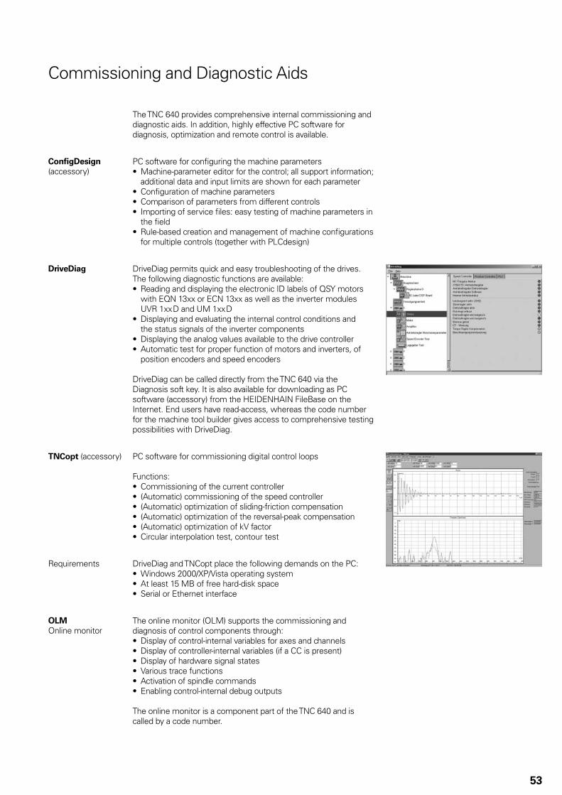
53
Commissioning and Diagnostic Aids
The TNC 640 provides comprehensive internal commissioning and diagnostic aids. In addition, highly effective PC software for diagnosis, optimization and remote control is available.
Confi gDesign
(accessory)PC software for confi guring the machine parameters
Machine-parameter editor for the control; all support information; • additional data and input limits are shown for each parameterConfi guration of machine parameters• Comparison of parameters from different controls• Importing of service fi les: easy testing of machine parameters in • the fi eldRule-based creation and management of machine confi gurations • for multiple controls (together with PLCdesign)
DriveDiag DriveDiag permits quick and easy troubleshooting of the drives. The following diagnostic functions are available:
Reading and displaying the electronic ID labels of QSY motors • with EQN 13xx or ECN 13xx as well as the inverter modules UVR 1xx D and UM 1xx DDisplaying and evaluating the internal control conditions and • the status signals of the inverter componentsDisplaying the analog values available to the drive controller• Automatic test for proper function of motors and inverters, of • position encoders and speed encoders
DriveDiag can be called directly from the TNC 640 via the Diagnosis soft key. It is also available for downloading as PC software (accessory) from the HEIDENHAIN FileBase on the Internet. End users have read-access, whereas the code number for the machine tool builder gives access to comprehensive testing possibilities with DriveDiag.
TNCopt (accessory) PC software for commissioning digital control loops
Functions:Commissioning of the current controller• (Automatic) commissioning of the speed controller• (Automatic) optimization of sliding-friction compensation• (Automatic) optimization of the reversal-peak compensation• (Automatic) optimization of kV factor• Circular interpolation test, contour test•
Requirements DriveDiag and TNCopt place the following demands on the PC:Windows 2000/XP/Vista operating system• At least 15 MB of free hard-disk space• Serial or Ethernet interface•
OLM
Online monitorThe online monitor (OLM) supports the commissioning and diagnosis of control components through:
Display of control-internal variables for axes and channels• Display of controller-internal variables (if a CC is present)• Display of hardware signal states• Various trace functions• Activation of spindle commands• Enabling control-internal debug outputs•
The online monitor is a component part of the TNC 640 and is called by a code number.

54
Oscilloscope The TNC 640 features an integrated oscilloscope. Both X/t and X/Y graphs are possible. The following characteristic curves can be recorded and stored in six channels:
Actual value of axis feed rate• Nominal value of axis feed rate• Contouring feed rate• Actual position• Nominal position• Following error of the position controller• Nominal values for speed, acceleration and jerk• Actual values for speed, acceleration and jerk• Content of PLC operands• Encoder signal (0° – A)• Encoder signal (90° – B)• Difference between position and speed encoder• Nominal velocity value• Integral-action component of the nominal current value• Torque-determining nominal current value•
Logic signals Simultaneous graphic representation of the logic states of up to 16 operands (markers, words, inputs, outputs, counters, timers)
Marker (M)• Input (I)• Output (O)• Timer (T)• Counter (C)• IpoLogic (X)•
TNCscope
(accessory)PC software for transferring the oscilloscope fi les to the PC.Note: The trace fi les are saved in the TNCscope data format.
API DATA The API DATA function enables the control to display the states or contents of the symbolic API markers and API double words. This function requires that your PLC program use the new symbolic memory interface.
Note:
The API DATA function does not provide usable display values with the iTNC 530-compatible memory interface (API 1.0).
Table function The current conditions of the markers, words, inputs, outputs, counters and timers are displayed in tables. The conditions can be changed through the keyboard.
Trace function The current content of the operands and the accumulators is shown in the instruction list in each line in HEX or decimal code. The active lines of the instruction list are marked.
Log For the purposes of error diagnosis, there is one log for all error messages and one for all keystrokes.
TeleService
(accessory)PC software for remote diagnosis, remote monitoring, and remote control of the TNC 640. For further information, ask for the Remote Diagnosis with TeleService Technical Information sheet.
Bus diagnostics In Diagnosis mode, the structure of the HSCI/PROFIBUS system as well as the details of the HSCI/PROFIBUS components can be displayed in a clearly laid out screen. For HSCI components this is possible even to the level of individual terminals.

55
Integral PLC
The PLC program is created by the machine tool builder either at the control or using the PLC development software PLCdesign
(accessory).
Machine-specifi c functions are activated and monitored via the PLC inputs/outputs. The number of PLC inputs/outputs required depends on the complexity of the machine.
PLC inputs/outputs PLC inputs and outputs are available via the external PL 6xxx PLC input/output systems or the UEC 11x.The PLC inputs/outputs and the PROFIBUS-DP-capable input/output system must be confi gured with the PC software IOconfi g.
PLC programming Format Statement list
Memory At least 1 GB RAM
Cycle time Typically 21 ms, adjustable
Instruction set • Bit, byte and word commands • Logical operations • Arithmetic commands • Comparisons • Nested calculations (parentheses) • Jump commands • Subroutines • Stack operations • Submit programs • 952 timers • 48 counters • Comments • PLC modules • 100 strings

56
PLC window PLC error messages can be displayed by the TNC 640 in the dialog line during operation.
Small PLC window The TNC 640 can show additional PLC messages and bar diagrams in the small PLC window.
PLC positioning All closed-loop axes can be also positioned via the PLC. PLC positioning of the NC axes cannot be superimposed over NC positioning.
PLC axes Axes can be controlled by the PLC. They are programmed by M functions or OEM cycles.The PLC axes are positioned independently of the NC axes.
PLC soft keys The machine manufacturer can display his own PLC soft keys in the vertical soft-key row on the screen.
Small PLC window ......
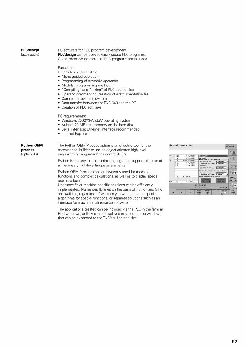
57
PLCdesign
(accessory)PC software for PLC program development.PLCdesign can be used to easily create PLC programs. Comprehensive examples of PLC programs are included.
Functions:Easy-to-use text editor• Menu-guided operation• Programming of symbolic operands• Modular programming method• “Compiling” and “linking” of PLC source fi les• Operand commenting, creation of a documentation fi le• Comprehensive help system• Data transfer between the TNC 640 and the PC• Creation of PLC soft keys•
PC requirements:Windows 2000/XP/Vista/7 operating system• At least 20 MB free memory on the hard disk• Serial interface; Ethernet interface recommended• Internet Explorer•
Python OEM
process
(option 46)
The Python OEM Process option is an effective tool for the machine tool builder to use an object-oriented high-level programming language in the control (PLC).
Python is an easy-to-learn script language that supports the use of all necessary high-level language elements.
Python OEM Process can be universally used for machine functions and complex calculations, as well as to display special user interfaces.User-specifi c or machine-specifi c solutions can be effi ciently implemented. Numerous libraries on the basis of Python and GTK are available, regardless of whether you want to create special algorithms for special functions, or separate solutions such as an interface for machine maintenance software.
The applications created can be included via the PLC in the familiar PLC windows, or they can be displayed in separate free windows that can be expanded to the TNC’s full screen size.

58
PLC basic program The PLC basic program serves as a basis for adapting the TNC 640 to the requirements of the respective machine. It can be downloaded from the Internet.
These essential functions are covered by the PLC basic program:Controlling all axes• Clamped axes• Homing the axes; reference end positions• Positioning the axes after reference run• Compensating the axis temperature• Assigning the C axis as lathe spindle• Feed rate control• Controlling and orienting the spindle• Activating tool-specifi c torque monitoring• Tool changer• Pallet changer (translational, rotatory, setup functions)• Vertical PLC soft-key row• Support for 19” screens• Displaying and managing PLC error messages• Status display in the small PLC window• Hydraulic control• Control of the coolant system (internal, external, air)• Handling M functions• Lubrication• Chip conveyor• Operation of the second spindle alternately with the fi rst• Wye/delta connection switchover (static, dynamic)• S-coded spindle• 3-D head with C-axis operation• Positioning the spindle as an axis• Operation with clamped axes• Axes with central drive• Axes with Hirth grid• Indexing fi xture• PLC log• Touch probes• PLC support for handwheels• Control of doors•

59
OEM Cycles (Option 19)
The machine tool builder can create and store his own cycles for recurring machining tasks. These OEM cycles are used in the same way as standard HEIDENHAIN cycles.
CycleDesign
(accessory)The soft-key structure for the OEM cycles is managed using the CycleDesign PC program. In addition, CycleDesign can be used to store help graphics and soft keys in BMP format on the hard disk of the TNC 640.Graphic fi les can be compressed to ZIP format to reduce the amount of memory used.
Tool Management
With integral PLC, the tool changer is moved either via proximity switch or as a controlled axis. The TNC 640 is responsible for all tool management, including tool-life monitoring and replacement tool monitoring.
Tool measurement
(option 17)Tools can be measured and checked using the TT 140 tool touch probe (accessory). The TNC 640 provides standard cycles for automatic tool measurement. It calculates the probing feed rate and the optimal spindle speed. The measured data is stored in a tool table.
Touch-Probe Confi guration (Option 17)
All touch-probe data can be confi gured conveniently through a table. All HEIDENHAIN touch probe systems are preconfi gured and can be selected through a drop-down menu.
Pallet Management
Pallet movement can be controlled via PLC axes. The order of movement, as well as pallet and workpiece datums, must be defi ned in the pallet table by the user.The pallet table is freely confi gurable, which means that any information can be stored in the tables and called up later by the PLC.
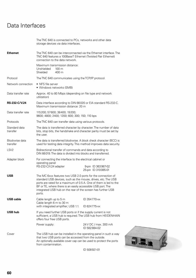
60
The TNC 640 is connected to PCs, networks and other data storage devices via data interfaces.
Ethernet The TNC 640 can be interconnected via the Ethernet interface. The TNC 640 features a 100BaseT Ethernet (Twisted Pair Ethernet) connection to the data network.
Maximum transmission distance:Unshielded 100 mShielded 400 m
Protocol The TNC 640 communicates using the TCP/IP protocol.
Network connection NFS fi le server• Windows networks (SMB)•
Data transfer rate Approx. 40 to 80 Mbps (depending on fi le type and network utilization)
RS-232-C/V.24 Data interface according to DIN 66 020 or EIA standard RS-232-C.Maximum transmission distance: 20 m
Data transfer rate 115 200; 57 600; 38 400; 19 200;9600; 4800; 2400; 1200; 600; 300; 150; 110 bps
Protocols The TNC 640 can transfer data using various protocols.
Standard data transfer
The data is transferred character by character. The number of data bits, stop bits, the handshake and character parity must be set by the user.
Blockwise data transfer
The data is transferred blockwise. A block check character (BCC) is used for testing data integrity. This method improves data security.
LSV2 Bidirectional transfer of commands and data according to DIN 66 019. The data is divided into blocks and transferred.
Adapter block For connecting the interface to the electrical cabinet or operating panelRS-232-C/V.24 adapter 9-pin ID 363 987-02 25-pin ID 310 085-01
USB The MC 6xxx features two USB 2.0 ports for the connection of standard USB devices, such as the mouse, drives, etc. The USB ports are rated for a maximum of 0.5 A. One of them is led to the BF or TE, where there is an easily accessible USB port. The integrated USB hub on the rear of the screen has further USB ports.
USB cable Cable length up to 5 m ID 354 770-xxCable length 6 m to 30 m with integrated amplifi er; USB 1.1. ID 624 775-xx
USB hub If you need further USB ports or if the supply current is not suffi cient, a USB hub is required. The USB hub from HEIDENHAIN offers four free USB ports.
Power supply: 24 V DC / max. 300 mA ID 582 884-02
Cover The USB hub can be installed in the operating panel in such a way that two USB ports can be accessed from the outside. An optionally available cover cap can be used to protect the ports from contamination.
ID 508 921-01
Data Interfaces

61
Software for Data Transfer
TNCremo
(accessory)This PC software package helps the user to transfer data from the PC to the TNC 640. The software on the PC carries out block-wise data transfer with block check character (BCC).
Functions:Data transfer (also blockwise)• Remote control (only serial)• File management and data backup of the TNC 640• Reading out the log• Print-out of screen contents• Text editor• Managing more than one machine•
Requirements:Windows 2000/XP/Vista/7 operating system• At least 10 MB free hard-disk space• Serial or Ethernet interface•
TNCremoPlus
(accessory)In addition to the features you are already familiar with from TNCremo, TNCremoPlus can also transfer the current content of the control’s screen to the PC (live screen). This makes it very simple to monitor the machine.ID 340 447-xx
Remote Desktop
Manager
(option 133)
Remote operation and display of external computer units via Ethernet connection (e.g. to a Windows PC)The information is displayed on the control’s screen.ID 894 423-01
DNC Applications
The development environments on Windows operating systems are particularly well suited as fl exible platforms for application development in order to come to terms with the increasingly complex requirements of the machine’s environment. The fl exibility of the PC software and the large selection of ready-to-use software components and standard tools in the development environment enable you to develop PC applications of great use to your customers in a very short time, for example:
Error reporting systems that, for example, send the customer a • text message to his cell phone reporting problems on the currently running machining processStandard or customer-specifi c PC software that decidedly • increases process security and equipment availabilitySoftware solutions controlling the processes of manufacturing • systemsInformation exchange with job management software•
HEIDENHAIN DNC
(option 18)The HEIDENHAIN DNC software interface is an attractive communication platform for this purpose. It provides all the data and confi guration capabilities needed for these processes so that an external PC application can evaluate data from the control and, if required, infl uence the manufacturing process.
RemoTools SDK
(accessory)To enable you to use HEIDENHAIN DNC effectively, HEIDENHAIN offers the RemoTools SDK development package. It contains the COM components and the ActiveX control for integration of the DNC functions in development environments.
ID 340 442-xx
For more information, refer to the HEIDENHAIN DNC brochure.
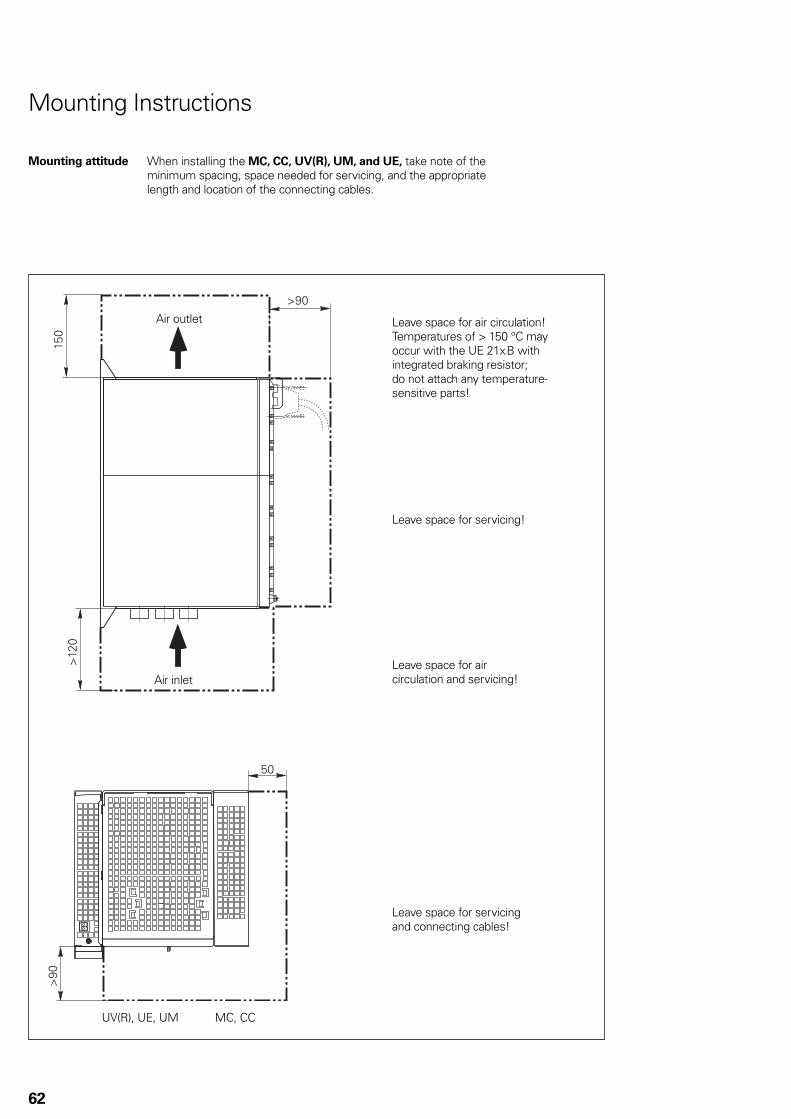
62
UV(R), UE, UM MC, CC
Mounting Instructions
Mounting attitude When installing the MC, CC, UV(R), UM, and UE, take note of the minimum spacing, space needed for servicing, and the appropriate length and location of the connecting cables.
Leave space for air circulation!Temperatures of > 150 °C may occur with the UE 21x B with integrated braking resistor;do not attach any temperature-sensitive parts!
Leave space for servicing!
Leave space for air circulation and servicing!
Leave space for servicing and connecting cables!
Air outlet
Air inlet
63
Mounting and
electrical
installation
Keep the following in mind during mounting and electrical installation:
National regulations for power installations• Interference and noise immunity• Conditions of operation• Mounting attitude•
Degrees of
protection
The following components fulfi ll the requirements for IP 54 (dust protection and splash-proof protection):
Visual display unit (when properly installed)• Keyboard unit (when properly installed)• Machine operating panel (when properly installed)• Handwheel•
All electric and electronic control components must be installed in an environment (e.g. electrical cabinet, housing) that fulfi lls the requirements of protection class IP 54 (dust and splash-proof protection) in order to fulfi ll the requirements of contamination level 2.
All components of the OEM operating panel must also comply with protection class IP 54, just like the HEIDENHAIN operating panel components.
Electromagnetic compatibility
Intended place of operation
The unit fulfi lls the requirements for a Class A device in accordance with the specifi cations in EN 55 022, and is intended for use in industrially zoned areas.
Protect your equipment from interference by observing the rules and recommendations specifi ed in the Technical Manual.
Likely sources of interference
Noise is mainly produced by capacitive and inductive coupling from electrical conductors or from device inputs/outputs, such as:
Strong magnetic fi elds from transformers or electric motors• Relays, contactors and solenoid valves• High-frequency equipment, pulse equipment and stray magnetic • fi elds from switch-mode power suppliesPower lines and leads to the above equipment•
Protective measures Keep a minimum distance of 20 cm from the MC, CC and its • leads to devices that carry interference signals.Keep a minimum distance of 10 cm from the MC, CC and its • leads to cables that carry interference signals. For cables in metallic ducting, adequate decoupling can be achieved by using a grounded separation shield.Shielding according to EN 50 178• Use equipotential bonding conductors with a cross section of • 6 mm2
Use only genuine HEIDENHAIN cables, connectors and • couplings
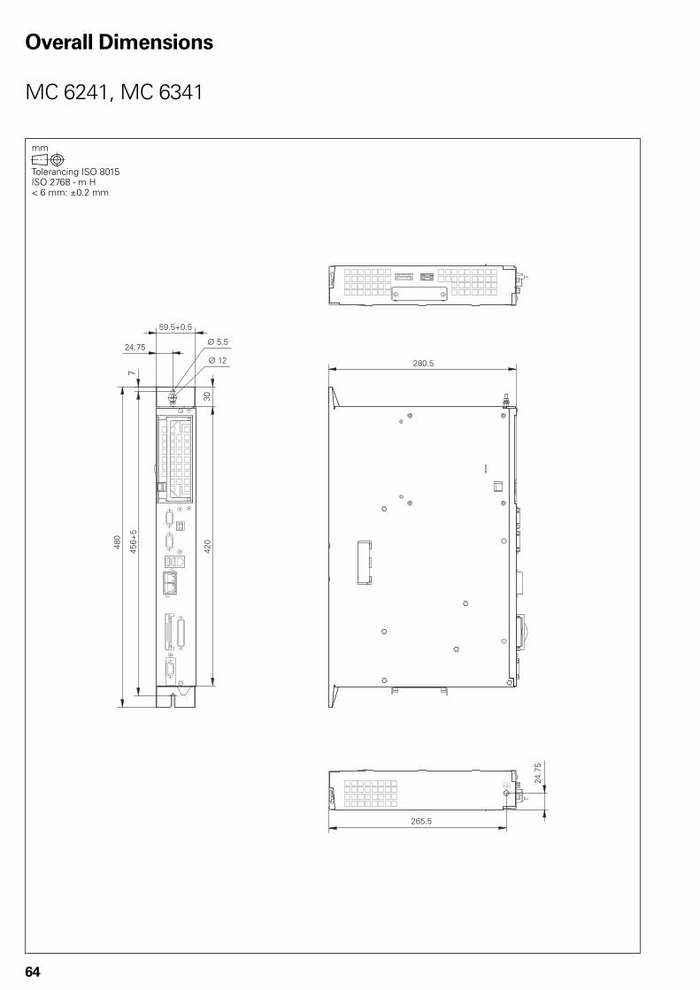
�+,-.
�/.-.
��-0.
��-0.
.1-.2,-.
�./2.
0
�+,
�,��,
#�.-.
#���
64
Overall Dimensions
MC 6241, MC 6341

�+,-. ��-.2��,��,
�./2.
0
�+,
��-0.
�.
0�-.2,-.
#�.-.
#���
65
CC 6106

�,��,
�./2.
0
�+,
��-0.
.,3,-�
11-.2,-.
#�.-.
#��� �+,-. ��-.2�
66
CC 6108, CC 6110
CC 6108: 8 control loopsCC 6110: 10 control loops
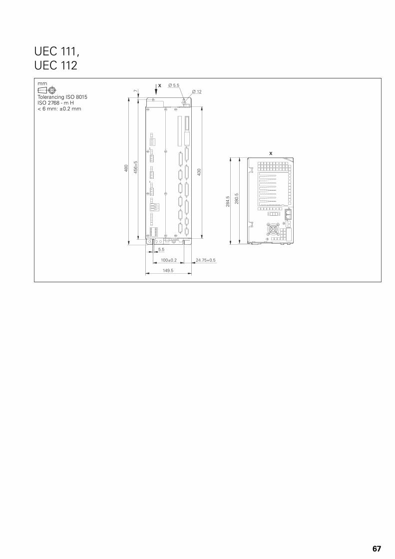
�./2.
�+,
0
.-.
�,,3,-� ��-0.2,-.
��1-.
#�.-.#���
��,
�+,-.
�+�-.
67
UEC 111, UEC 112
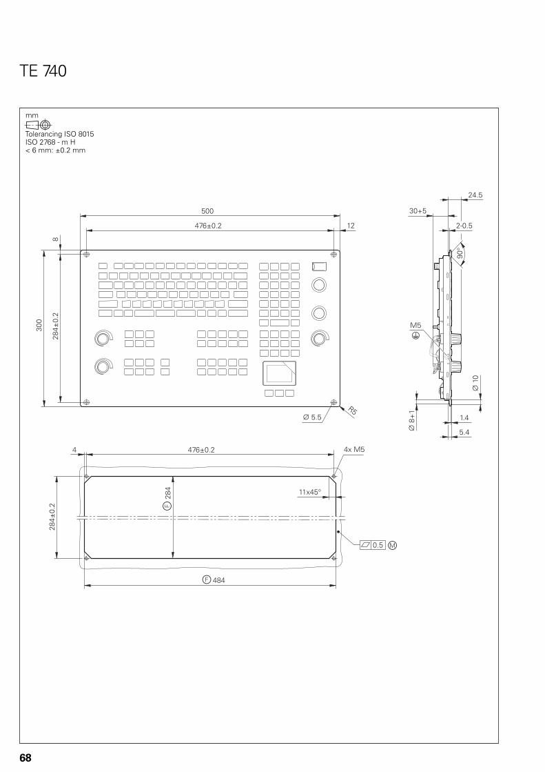
��4�.5
�0/3,-��
,-. �
��+�
�+��
�4��.
�+�3,-�
�+�3,-�
+
�,,
�0/3,-� ��
.,,
.#�.-. �-�
.-�#�+2�
#��,
�.�
�6,-.
�,2.
��-.
1,5
68
TE 740

��4�.5
�0/3,-��
,-. �
����
�+��
�4��.
���3,-�
#�+2�
�-�
#��,
�.2.
�6,-1
1,5
�0-�
.-�
�.�
�0/3,-� ��
.,,
���3,-�
+
�.,
#�.-..
69
TE 745
f = Cutout in machine panelm = Mounting surface

��.
/0
�+-�
0�2�
�,
#��,
�,
1,5
�-�
�6,-.
�
+2��0/3,-� ��
.,,
�+�3,-�
+
�,,
#�.-..
��
�0+
��.
++
��-.
�0/-�.
�+/���
�
�
�0/
�+�3,-�
�+,3,-.
��4�.5
�+,3,-.
�
�
,-. �
�4��.
1
1 .-�
70
BF 760
f = Cutout in machine panelm = Mounting surfaceb = Space for air circulation
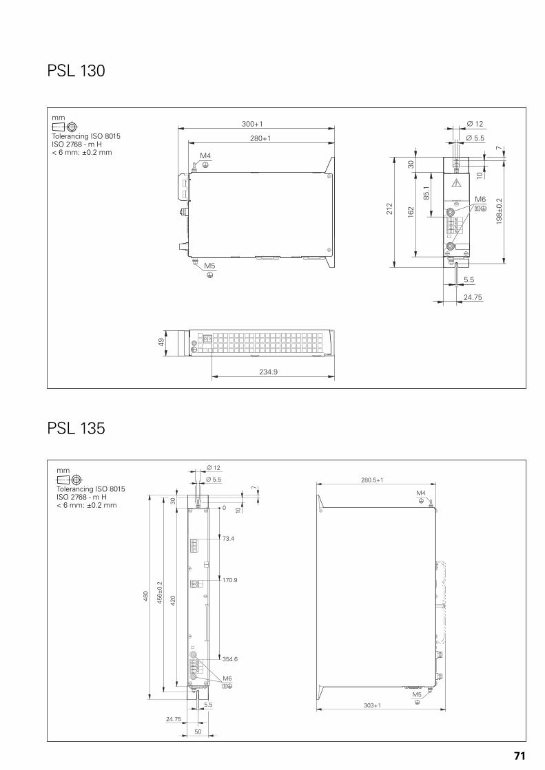
���-1
�1 �
#� $
#���
���%
�$�
�,
0
�,�/�
+.-�
���
.-.
��-0.
���/
�+,2�
�,,2�
���
�.�
#� $
#���
�,
0
�
�
�$
���$�
$�
.-.
��-0.
��
�%
�$�
��
�+,-.2�
�,�2�
���
�.�
.,
���/
71
PSL 130
PSL 135
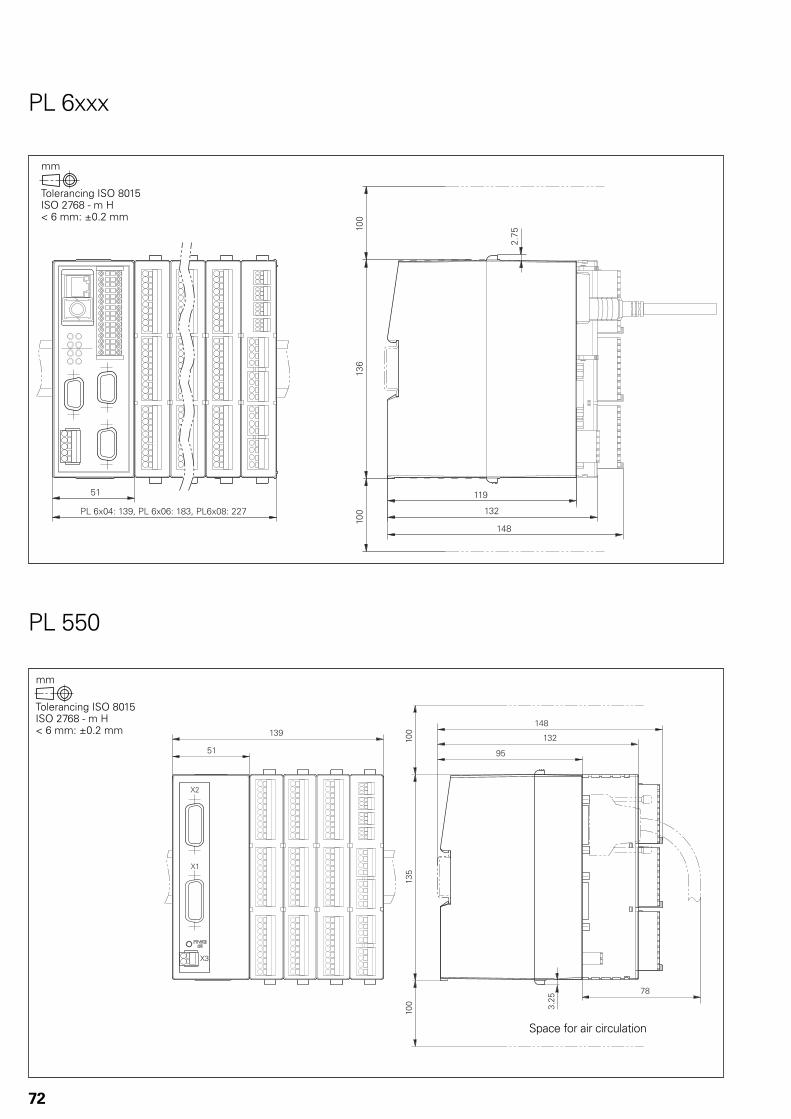
��1
���
��+
�-0.
��/
.�
� �/4,�7���18�� �/4,/7��+�8�� /4,+7���0
�,,
�,,
1.
���
��+
0+
��.
�-�.
.�
��1
9�
9�
9�
�,,
�,,
72
PL 6xxx
PL 550
Space for air circulation
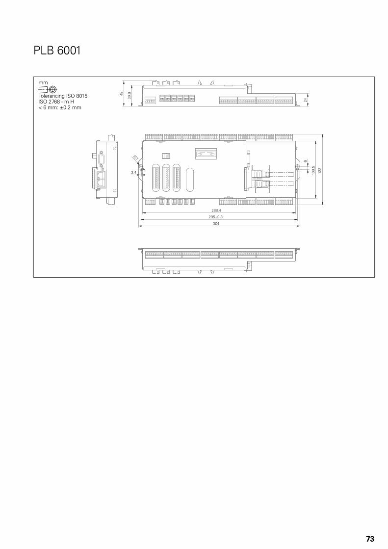
�++-�
�1.%�$
�,�
�,1-.
���
�-�
#�
/
�1-1�+
��
73
PLB 6001
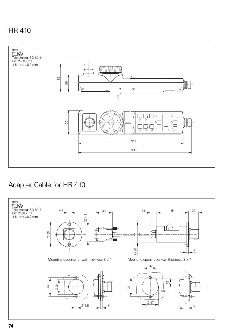
�� ��
���
�
����
�
����
#��
�
� �
��
��
#���
��
#��
�
#���
��
��
74
Adapter Cable for HR 410
HR 410
Mounting opening for wall thickness S † 4 Mounting opening for wall thickness S > 4
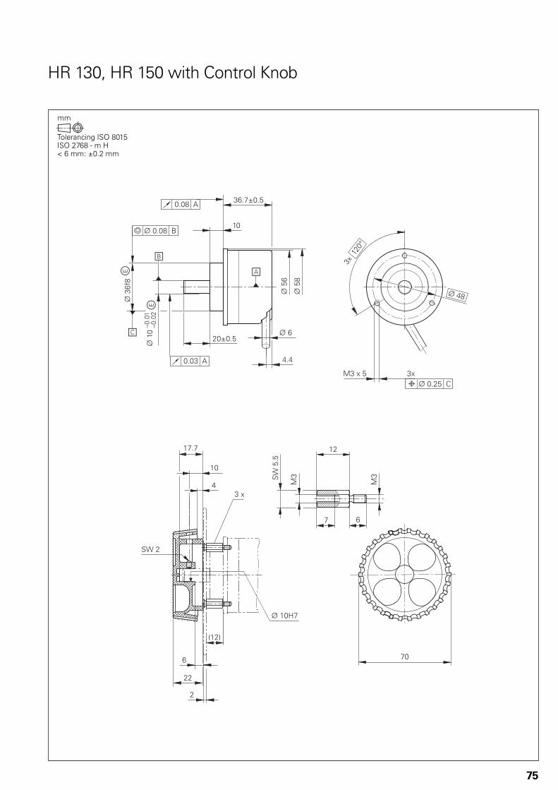
�/-03,-.
#�/
�,
�,3,-.
�-�,-,����
,-,+���
#�,-,+���
#�./
#�.+
#��/%+
��
�
#��,�:,-,�
�����������:,-,�
�
�
�4����,5
#��+
#�,-�.����4���4�.
75
HR 130, HR 150 with Control Knob

��
��� ������
#�
���
�
��������
�����������
��
�
������
���
��
�
� ���
�
76
HRA 110
Step Switch
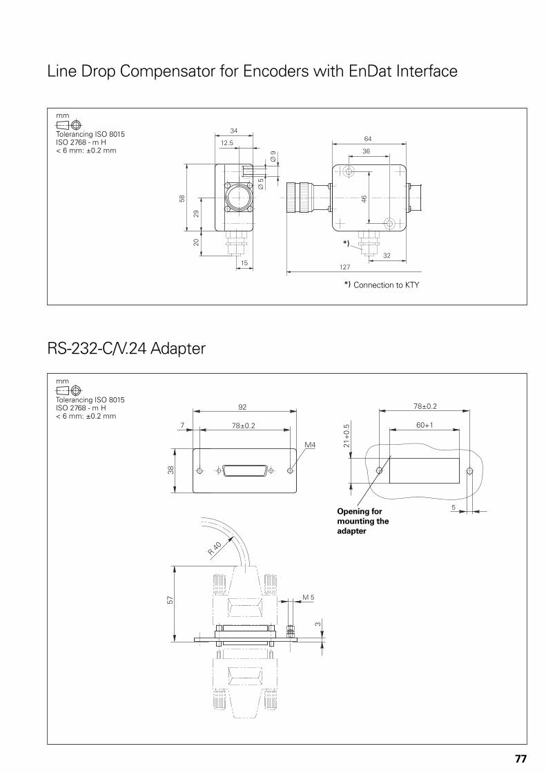
��0
/���-.
��
�1
.+
�/
�/
6+
�.
�,
��
6+
#�
#��
77
Line Drop Compensator for Encoders with EnDat Interface
RS-232-C/V.24 Adapter
Connection to KTY
Opening for
mounting the
adapter

3
3
.,�
�+
�0
�,1
�0-.
/+
1�-�
�,,3,-�
#�$.,3,-�
0,3,-�
��
/,3,-�
+,
�,
�0-.
�,3,-�
#��$
#�$
�
�+,5
�1
��4�.,,, .,,,�,,,---.,,,
��.
#���
���:� ���:�
78
USB Hub
USB Extension Cable with Hubs
n = 0 ... 4L = Length ordered
79
Documentation
Items supplied with the control include:1 User’s Manual for HEIDENHAIN conversational programming• 1 User’s Manual for DIN/ISO programming• 1 User’s Manual for Cycle Programming•
This documentation must be ordered separately in the language required.Further documentation is available from HEIDENHAIN.
Technical
documentation
TNC 640• Technical Manual ID 892 899-xx;in PDF format on the HESIS web including FileBase
Inverters and Motors• Technical Manual ID 208 962-xx
TS 220• Mounting Instructions ID 312 821-91TS 440• Mounting Instructions ID 632 756-9xTS 444• Mounting Instructions ID 632 757-9xTS 640• Mounting Instructions ID 632 760-9xTS 740• Mounting Instructions ID 632 761-9xTT 140• Mounting Instructions ID 297 510-xxTT 449• Mounting Instructions ID 664 914-xx
User documentation TNC 640
Conversational• User’s Manual ID 892 903-xxTouch-Probe Cycles• User’s Manual ID 892 905-xxDIN/ISO• User’s Manual ID 892 909-xx
Miscellaneous
TNCremo• User’s Manual As integrated help and in PDF formatTNCremoPlus• User’s Manual As integrated help and in PDF formatPLCdesign• User’s Manual As integrated help and in PDF formatCycleDesign• User’s Manual As integrated help and in PDF formatIOconfi g• User’s Manual As integrated help and in PDF formatKinematicsDesign• User’s Manual As integrated help and in PDF format
Other
documentation
TNC 640• brochure ID 892 916-xxTouch Probes• brochure ID 208 951-xxInverter Systems• brochure ID 622 420-xxMotors• brochure ID 208 893-xxHEIDENHAIN DNC• brochure PDFRemote Diagnosis with TeleService• Product Overview ID 348 236-xxTouch Probes• CD-ROM ID 344 353-xxTNC 640 Programming Station• CD-ROMdemo version in preparationUniformly Digital• Technical Information sheet PDF

80
HEIDENHAIN Service
Technical support HEIDENHAIN offers the machine tool builder technical support to optimize the adaptation of the TNC to the machine—including on-site support.
Replacement
control system
In the event of a fault, HEIDENHAIN guarantees the rapid supply of a replacement control system (usually within 24 hours in Europe).
Hotline Our service engineers are naturally at your disposal by telephone if you have any questions on the interfacing of the control or in the event of faults.
TNC support { +49 8669 31-3101 E-mail: [email protected] programming { +49 8669 31-3102 E-mail: [email protected] programming { +49 8669 31-3103 E-mail: [email protected] systems { +49 8669 31-3104 E-mail: [email protected] controls { +49 8669 31-3105 E-mail: [email protected]
Machine calibration On request, HEIDENHAIN engineers will calibrate your machine’s geometry, for example with a KGM grid encoder.
Seminars
HEIDENHAIN provides technical customer training in the following subjects:
NC programming• PLC programming• TNC optimization• TNC service• Encoder service• Special training for specifi c customers•
For more information on dates, registration, etc. call in Germany:{ +49 8669 31-2293 or 31-1695| +49 8669 31-1999E-mail: [email protected]

81
Other HEIDENHAIN Controls
iTNC 530
Information:BrochureiTNC 530
Contouring control for • milling, drilling and boring machines,
and machining centers
Up to 18 axes and controlled main spindle• HEIDENHAIN inverter systems and motors recommended• Uniformly digital with HSCI interface and EnDat interface• TFT color fl at-panel display, 15-inch or 19-inch• Storage medium: HDR hard disk with 160 GB / SSDR solid state • disk with 32 GBProgramming in HEIDENHAIN conversational format, with • smarT.NC or according to DIN/ISOStandard milling, drilling and boring cycles• Touch probe cycles• FK free contour programming• Special functions for fast 3-D machining• Short block processing time (0.5 ms)• Automatic calculation of cutting data• Pallet management•
TNC 620
Information: Brochure TNC 620
Contouring control for • milling machines
Up to 5 axes and controlled main spindle• HEIDENHAIN inverter systems and motors recommended• Uniformly digital with HSCI interface and EnDat interface• Compact design:• – Screen, keyboard and main computer in one unit (MC 7110)– Screen and main computer in one unit (MC 7120) and separate
keyboard with integrated ASCII keysDimensions: 400 mm x 470 mm x 100 mm• Integrated 15-inch TFT fl at-panel display• Storage medium for NC programs: CompactFlash memory card• Programming in HEIDENHAIN conversational format or • according to DIN/ISOStandard milling, drilling and boring cycles• Touch probe cycles• Short block processing time (1.5 ms)•
CNC PILOT 620
Information: Brochure CNC PILOT 620
Contouring control for • horizontal and vertical lathes
Up to 3 axes (X, Z and Y), controlled spindle and counterspindle, • C1/C2 axis and driven toolsUp to 3 programmable auxiliary axes (U, V, W) for control of • steady rest, tailstock and counterspindleThe position of a parallel secondary axis can be shown • combined with its principal axis.HEIDENHAIN inverter systems and motors recommended• Uniformly digital with HSCI interface and EnDat interface• 19-inch TFT fl at-panel display• Storage medium: CompactFlash memory card• Programming of turning, drilling and milling operations with • smart.Turn, according to DIN/ISO or via cyclesFree ICP contour programming for turning and milling contours•
Symbols5-axis machining ..................................... 4119-inch screen ......................................... 25
AAbsolute encoders .................................. 49Accessories ............................................... 8API DATA ................................................. 54Axes ........................................................ 40Axis clamping .......................................... 40Axis feedback control ............................. 46
BBasic modules ........................................ 26BF 760 ............................................... 25, 70Block processing times, short ................ 48Bus diagnosis .......................................... 54
CCable overview ....................................... 36Calibration sphere ................................... 51CC 6106............................................. 23, 65CC 6108............................................. 23, 66CC 6110 ............................................. 23, 66CMA-H 04-04-00 ..................................... 32Commissioning and diagnostic aids ....... 53Compensation of torque ripples ............. 46Confi gDesign .......................................... 53Context-sensitive help ............................ 52Controller unit ......................................... 22Control loop cycle times ......................... 47CycleDesign ............................................ 59Cylinder surface interpolation ................. 40
DData interfaces ........................................ 60Degrees of protection ............................ 63Digital control .......................................... 46DNC applications .................................... 61Documentation ....................................... 79Double-speed .......................................... 22Double-speed control loops ................... 47DriveDiag................................................. 53
EElectromagnetic compatibility ................ 63Electronic handwheels ........................... 30Encoders ................................................. 49Error compensation ................................ 50Ethernet .................................................. 60Expansion PL .......................................... 26Export version ......................................... 18
GGantry axes ............................................. 42Gear stages ............................................. 45
HHDR hard disk ......................................... 19HEIDENHAIN DNC ................................. 61HR 130 .............................................. 30, 75HR 150 .............................................. 31, 75HR 410 .............................................. 30, 74HRA 110 ............................................ 31, 76HSCI adapter for the OEM machine operating panel ........................ 32
IIncremental encoders............................. 49Integral PLC ............................................ 55Integrated inverters ................................ 46I/O modules ............................................ 27IPC 6341 ................................................. 21
JJerk .......................................................... 47Jerk limiting ............................................. 47
KKeyboard unit .......................................... 25KinematicsDesign ................................... 52KinematicsOpt ........................................ 51
LLinear axes .............................................. 40Linear error .............................................. 50Log .......................................................... 54Look-ahead .............................................. 48
MMachine confi guration ............................ 48Machine interfacing .................................. 6Main computer ....................................... 18Maximum spindle speed ........................ 45MC 6241 ................................................. 64MC 6341 ................................................. 64Module for analog axes .......................... 32Monitoring functions .............................. 52Mounting information ............................. 62
NNC software license ............................... 20Nonlinear errors ...................................... 50
OOEM cycles............................................. 59OLM Online monitor .............................. 53Operating-mode switchover ................... 45Oriented spindle stop ............................. 45Oscilloscope............................................ 54Overall dimensions ................................. 64
PPallet management ................................. 59PL 6xxx.............................................. 26, 72PL 550 ............................................... 28, 72PLB 550 .................................................. 28PLB 6001 ........................................... 32, 73PLC axes ........................................... 42, 56PLC basic program ................................. 58PLCdesign ............................................... 57PLC input/output systems ...................... 26PLC inputs/outputs ................................. 55PLC positioning ....................................... 56PLC programming .................................. 55PLC soft keys .......................................... 56PLC window ........................................... 56Position-controlled spindle ...................... 45Power supply for HSCI components ...... 29PSL 130 ............................................. 29, 71PSL 135 ............................................. 29, 71Python OEM process ............................. 57
RRemote Desktop Manager ..................... 61RemoTools SDK ...................................... 61Rotary axes ............................................. 40RS-232-C/V.24 ......................................... 60
SSecond spindle ....................................... 45SIK component ....................................... 19Single-speed ........................................... 22Smoother jerk ......................................... 47Snap-on keys for control ......................... 33Snap-on keys for HR 410 ........................ 34Software for data transfer ....................... 61Spindle .................................................... 45Spindle override ...................................... 45Storage medium ..................................... 19Synchronized axes .................................. 42System PL ............................................... 26
TTable function .......................................... 54Tapping .................................................... 45TE 740 ............................................... 25, 68TE 745 ............................................... 25, 69Technical description ............................... 40TeleService .............................................. 54Tilting the working plane ........................ 41TNC 640 .................................................... 2TNCopt .................................................... 53TNCremo................................................. 61TNCremoPlus ......................................... 61TNCscope ............................................... 54Tool management ................................... 59Tool measurement .................................. 35Torque control ......................................... 42Touch-probe confi guration ...................... 59Touch probes ........................................... 35Trace function.......................................... 54Turning ..................................................... 43
UUEC 11x .................................................. 24UEC 111 ............................................. 24, 67UEC 112 ............................................ 24, 67USB ......................................................... 60User functions ........................................ 10
VVersions ................................................... 18
WWorkpiece measurement ....................... 35
82
Subject Index


NO HEIDENHAIN Scandinavia AB7300 Orkanger, Norwaywww.heidenhain.no
PH Machinebanks` CorporationQuezon City, Philippines 1113E-mail: [email protected]
PL APS02-489 Warszawa, Polandwww.apserwis.com.pl
PT FARRESA ELECTRÓNICA, LDA.4470 - 177 Maia, Portugalwww.farresa.pt
RO HEIDENHAIN Reprezentanta RomaniaBrasov, 500338, Romaniawww.heidenhain.ro
RS Serbia − BG
RU OOO HEIDENHAIN125315 Moscow, Russiawww.heidenhain.ru
SE HEIDENHAIN Scandinavia AB12739 Skärholmen, Swedenwww.heidenhain.se
SG HEIDENHAIN PACIFIC PTE LTD.Singapore 408593www.heidenhain.com.sg
SK KOPRETINA TN s.r.o.91101 Trencin, Slovakiawww.kopretina.sk
SL Posredništvo HEIDENHAINNAVO d.o.o.2000 Maribor, Sloveniawww.heidenhain-hubl.si
TH HEIDENHAIN (THAILAND) LTDBangkok 10250, Thailandwww.heidenhain.co.th
TR T&M Mühendislik San. ve Tic. LTD. STI·.
34728 Ümraniye-Istanbul, Turkeywww.heidenhain.com.tr
TW HEIDENHAIN Co., Ltd.Taichung 40768, Taiwan R.O.C.www.heidenhain.com.tw
UA Gertner Service GmbH Büro Kiev 01133 Kiev, Ukrainewww.gertnergroup.com
US HEIDENHAIN CORPORATIONSchaumburg, IL 60173-5337, USAwww.heidenhain.com
VE Maquinaria Diekmann S.A. Caracas, 1040-A, VenezuelaE-mail: [email protected]
VN AMS Co. LtdHCM City, VietnamE-mail: [email protected]
ZA MAFEMA SALES SERVICES C.C.Midrand 1685, South Africawww.heidenhain.co.za
DK TP TEKNIK A/S2670 Greve, Denmarkwww.tp-gruppen.dk
ES FARRESA ELECTRONICA S.A.08028 Barcelona, Spainwww.farresa.es
FI HEIDENHAIN Scandinavia AB02770 Espoo, Finlandwww.heidenhain.fi
FR HEIDENHAIN FRANCE sarl92310 Sèvres, Francewww.heidenhain.fr
GB HEIDENHAIN (G.B.) LimitedBurgess Hill RH15 9RD, United Kingdomwww.heidenhain.co.uk
GR MB Milionis Vassilis17341 Athens, Greecewww.heidenhain.gr
HK HEIDENHAIN LTDKowloon, Hong KongE-mail: [email protected]
HR Croatia − SL
HU HEIDENHAIN Kereskedelmi Képviselet1239 Budapest, Hungarywww.heidenhain.hu
ID PT Servitama Era ToolsindoJakarta 13930, IndonesiaE-mail: [email protected]
IL NEUMO VARGUS MARKETING LTD.Tel Aviv 61570, IsraelE-mail: [email protected]
IN HEIDENHAIN Optics & ElectronicsIndia Private LimitedChetpet, Chennai 600 031, Indiawww.heidenhain.in
IT HEIDENHAIN ITALIANA S.r.l.20128 Milano, Italywww.heidenhain.it
JP HEIDENHAIN K.K.Tokyo 102-0083, Japanwww.heidenhain.co.jp
KR HEIDENHAIN Korea LTD.Gasan-Dong, Seoul, Korea 153-782www.heidenhain.co.kr
ME Montenegro − SL
MK Macedonia − BG
MX HEIDENHAIN CORPORATION MEXICO20235 Aguascalientes, Ags., MexicoE-mail: [email protected]
MY ISOSERVE Sdn. Bhd56100 Kuala Lumpur, MalaysiaE-mail: [email protected]
NL HEIDENHAIN NEDERLAND B.V.6716 BM Ede, Netherlandswww.heidenhain.nl
AR NAKASE SRL.B1653AOX Villa Ballester, Argentinawww.heidenhain.com.ar
AT HEIDENHAIN Techn. Büro Österreich83301 Traunreut, Germanywww.heidenhain.de
AU FCR Motion Technology Pty. LtdLaverton North 3026, AustraliaE-mail: [email protected]
BA Bosnia and Herzegovina − SL
BE HEIDENHAIN NV/SA1760 Roosdaal, Belgiumwww.heidenhain.be
BG ESD Bulgaria Ltd.Sofi a 1172, Bulgariawww.esd.bg
BR DIADUR Indústria e Comércio Ltda.04763-070 – São Paulo – SP, Brazilwww.heidenhain.com.br
BY BelarusGERTNER Service GmbH50354 Huerth, Germanywww.gertnergroup.com
CA HEIDENHAIN CORPORATIONMississauga, OntarioL5T2N2, Canadawww.heidenhain.com
CH HEIDENHAIN (SCHWEIZ) AG8603 Schwerzenbach, Switzerlandwww.heidenhain.ch
CN DR. JOHANNES HEIDENHAIN (CHINA) Co., Ltd.Beijing 101312, Chinawww.heidenhain.com.cn
CZ HEIDENHAIN s.r.o.102 00 Praha 10, Czech Republicwww.heidenhain.cz
DE HEIDENHAIN Vertrieb Deutschland83301 Traunreut, Deutschland{ 08669 31-3132| 08669 32-3132E-Mail: [email protected]
HEIDENHAIN Technisches Büro Nord12681 Berlin, Deutschland{ 030 54705-240
HEIDENHAIN Technisches Büro Mitte08468 Heinsdorfergrund, Deutschland{ 03765 69544
HEIDENHAIN Technisches Büro West44379 Dortmund, Deutschland{ 0231 618083-0
HEIDENHAIN Technisches Büro Südwest70771 Leinfelden-Echterdingen, Deutschland{ 0711 993395-0
HEIDENHAIN Technisches Büro Südost83301 Traunreut, Deutschland{ 08669 31-1345
Vollständige und weitere Adressen siehe www.heidenhain.deFor complete and further addresses see www.heidenhain.de
Zu
m A
bh
eft
en
hie
r fa
lzen
! /
Fo
ld h
ere
fo
r fi
lin
g!
������������ ��� ��������������� ��������������������������������������� �������������� ������������������ ��!�"����������
������ !���� ��!�
896 020-21 · 10 · 9/2011 · H · Printed in Germany