infohouse.p2ric.orginfohouse.p2ric.org/ref/15/14355.pdf2007-10-10 · infohouse.p2ric.org
44
-
Upload
vuongkhanh -
Category
Documents
-
view
229 -
download
0
Transcript of infohouse.p2ric.orginfohouse.p2ric.org/ref/15/14355.pdf2007-10-10 · infohouse.p2ric.org


I
distillation terminology To provide a better understanding of the distillation process, the fol lowing briefly explains the terminology most often encountered.
SOLVENT RECOVERY The term "solvent recovery" often has been a somewhat vague label applied to the many and very different ways i n which solvents can be reclaimed by industry.
One approach employed i n the print ing and coatings industries is merely to take impure solvents containing both soluble and insoluble particles and evapo- rate the solvent f rom the solids. For a duty of this type, APV offers the Paraflash evaporator, a compact unit which combines a Paraflow plate heat exchanger and a small separator. As the solvent ladened liquid is recirculated through the heat exchanger, i t is evaporated and the vapor and liquid separated. This wi l l recover a solvent but i t will not separate solvents if two or more are present.
A fur ther technique is available to handle an air stream that carries solvents. By chil l ing the air by means of vent condensers or refrigeration equipment, the solvents can be removed from the condenser.
Solvents also can be recovered by using extraction, adsorption, absorption, and distillation methods.
S 0 LV E N T E XT R ACT I 0 N
Essentially a liquid/liquid process where one liquid is used to extract another from a secondary stream, solvent extraction generally is performed in a column somewhat similar to a normal disti l lation column. The primary difference is that the process involves two liquids instead of liquid and vapor.
During the process, the lighter (i.e., less dense) l iquid is charged to the base of the column and rises through packing or trays while the more dense liquid descends. Mass transfer occurs and a component is extracted from one stream and passed to the other.
Liquid/liquid extraction sometimes is used when the breaking of an azeotrope is difficult or impossible by distillation techniques.
CAR EON ADS OR PTI O N The carbon adsorption technique is used primarily to recover solvents f rom dilute air or gas streams.
In principle, a solvent ladened air stream is passed over activated carbon and the solvent is adsorbed into the carbon bed. When the bed becomes saturated, steam is used to desorb the solvent and carry it to a condenser. In such cases as toluene, for example, recovery of the solvent can be achieved simply by decanting the water/solvent two phase mixture which forms in the condensate. Carbon
4

I
the APV position With nearly 50 years of experience in the design of distillation equipment, the APV Group of companies ranks among the leaders in this field. As early as 1932, APV engineers developed the West plate which provided a good turndown ratio and highly efficient operation wi th low tray spacings. While this device has been superseded by modern valve trays that can offer similar turndown characteristics at lower cost, the many thousands of West plates still in operation attest to their durability and re I i a b i I i ty.
Today, APV CREPACO, Inc. offers con- siderable expertise in the design and fabrication of all types of distillation equipment and systems. As a member of the worldwide APV organization and of Fractionation Research Incorporated (FRI) of California, APV has access to specialists knowledgeable in both the theoretical and practical aspects of distillation, solvent recovery and pollution abatement. Further- more, well equipped laboratory facilities are available for extensive test work and the company can utilize the Chem Share process simulation programs to simplify tray to tray calculations for binary and multicomponent mixtures and to perform energy and material balance calculations in great detail.
In addition to providing a design and engineering service, APV also can fabricate equipment from various stainless steels, titanium, Monel, or nickel in sizes ranging from pilot plant units to column diameters of 12 feet or more. lnternals can include valve, sieve or bubble cap trays as well as many types of metal or ceramic packing.
In effect, a complete distillation service from the preliminary design through startup is available from a single, responsible source.
Fig 1 Pictured above are six large APV sodium carbonate regeneration columns being installed as key elements in an electric power generation pollution control program. Fabricated of stainless steel, the columns rise 68 to 70 feet high by 3 to 4 feet in diameter.
3

FIG 2 Portion of f lue gas desulfurization system
adsorption beds normally are used in pairs so that the air f low can be diverted to the secondary bed when required.
On occasions, the condensate is i n the form of a moderately dilute miscible mixture. The solvent then has to be recovered by distillation. This would apply especislly to ethyl alcohol, acetone type solvents.
ABSORPTION When carbon adsorption cannot be used because certain solvents either poison the activated carbon bed or create so much heat that the bed can ignite, absorption is an alternate technique. Solvent is recovered by pumping the solvent ladened air stream through a column countercurrently to a water stream which absorbs the solvent. The air f rom the top of the column essentially is solvent free whi le the dilute water/solvent stream discharged from the column bottom usually is concentrated in a disti l lation column. Absorption also can be applied in cases where an oil rather than water is used to absorb certain organic solvents from an air stream.
A2 EOTR 0 PES During distillation, some components form an azeotrope at a certain stage of the fractionation and require a th i rd component to break the azeotrope and achieve a higher percentage of concentration. In the case of ethyl alcohol and water, for example, a boiling mixture containing less than 96% by weight ethyl alcohol produces a vapor richer in alcohol than i n water and is readily distilled. A t the 96% by weight point, however, the ethyl alcohol composition in the vapor remains constant, i.e., the same composition as the boiling l iquid. This is known as the azeotrope composition and further concentration requires use of a process known as azeotropic distillation. Other common f luid mixtures which form azeotropes are formic acid/water, is0 propyl alcohol/water, and is0 butanol/water.
5

FIG 3 System for recovering butanol f rom butanol /water mlxture
AZEOTROPIC DISTILLATION In a typical azeotropic distillation procedure, a third component such as benzene, is0 propyl ether or cyclohexane is added to a n azeotropic mixture such as ethyl alcohol/water to form a ternary azeotrope. Since the ternary azeotrope is richer in water than the binary ethyl alcohol/water azeotrope, water is carried over the top of the column. The azeotrope, when condensed, forms two phases. The organic phase is refluxed to the column while the aqueous phase is discharged to a third column for recovery of the entraining agent.
Certain azeotropes such as the n-butanol/water mixture can be separated in a two column system without the use of a third component. When condensed and decanted, this type of azeotrope forms t w o phases. The organic phase is fed back to the primary column and the butanol recovered from the bottom of the still. The aqueous phase, meanwhile, is charged to the second column wi th the water being taken from the column bottom. The vapor from the top of both columns is condensed and the condensate run to a common decanter.
E XT R ACT I V E D I STI L L AT I 0 N This technique is somewhat similar to azeotropic distillation in that it is designed to perform the same type of task. In azeotropic distillation, the azeotrope is broken by carrying over a ternary azeotrope at the top of the column. In extractive distil- lation, a very high boiling compound is added and the solvent removed at the base of the column.
6
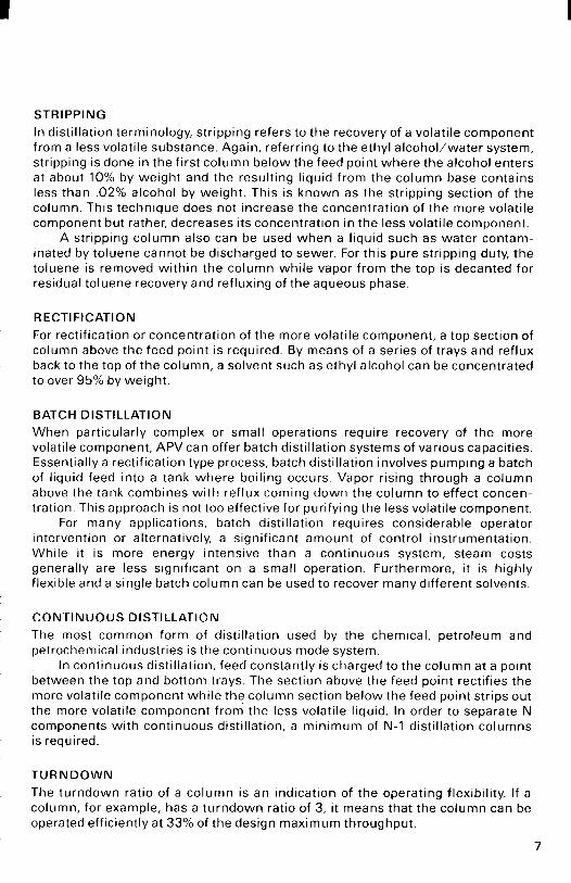
STRIPPING In distillation terminology, stripping refers to the recovery of a volatile component from a less volatile substance. Again, referring to the ethyl alcohol/water system, stripping is done i n the first column below the feed point where the alcohol enters at about 10% by weight and the resulting l iquid from the column base contains less than .02% alcohol by weight. This is known as the stripping section of the column. This technique does not increase the concentration of the more volatile component but rather, decreases its concentration in the less volatile component.
A stripping column also can be used when a l iquid such as water contam- inated by toluene cannot be discharged to sewer. For this pure stripping duty, the toluene is removed within the column while vapor from the top is decanted for residual toluene recovery and refluxing of the aqueous phase.
R E CT I F I C AT1 0 N For rectification or concentration of the more volatile component, a top section of column above the feed point is required By means of a series of trays and reflux back to the top of the column, a solvent such as ethyl alcohol can be concentrated to over 95% by weight
BAT C H D I STI L L AT I 0 N When particularly complex or small operations require recovery of the more volatile component, APV can offer batch distillation systems of various capacities. Essentially a rectification type process, batch distillation involves pumping a batch of liquid feed into a tank where boiling occurs. Vapor rising through a column above the tank combines w i th reflux coming down the column to effect concen- tration. This approach is not too effective for purifying the less volatile component.
For many applications, batch distillation requires considerable operator intervention or alternatively, a significant amount of control instrumentation. While it is more energy intensive than a continuous system, steam costs generally are less significant on a small operation. Furthermore, it is highly flexible and a single batch column can be used to recover many different solvents.
CONTl N U O U S D l STl LLATIO N The most common form of distillation used by the chemical, petroleum and petrochemical industries is the continuous mode system.
In continuous distillation, feed constantly is charged to the column at a point between the top and bottom trays. The section above the feed point rectifies the more volatile component whi le the column section below the feed point strips out the more volatile component from the less volatile liquid. In order to separate N components w i th continuous distillation, a minimum of N - l distillation columns is required.
T U R N D O W N The turndown ratio of a column is an indication of the operating flexibility If a column, for example, has a turndown ratio of 3, i t means that the column can be operated efficiently at 33% of the design maximum throughput
7
system components COLUMNS, INTERNALS, INSTRUMENTATION AND AUXILIARY EQUIPMENT
The following briefly defines the many components required for a distillation system and the many variations in components that are available to meet different process conditions.
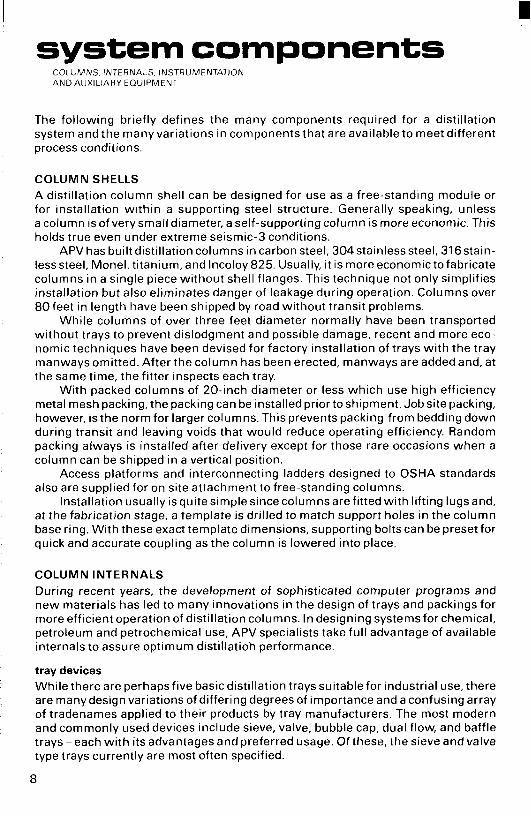
C O L U M N SHELLS A distillation column shell can be designed for use as a free-standing module or for installation wi th in a supporting steel structure. Generally speaking, unless a column is of very small diameter, a self-supporting column is more economic. This holds true even under extreme seismic-3 conditions.
APV has built distillation columns in carbon steel, 304stainless steel, 316stain- lesssteel, Monel, titanium, and lncoloy 825. Usually, it is more economic to fabricate columns in a single piece without shell flanges. This technique not only simplifies installation but also eliminates danger of leakage during operation. Columns over 80feet in length have been shipped by road without transit problems.
While columns of over three feet diameter normally have been transported without trays to prevent dislodgment and possible damage, recent and more eco- nomic techniques have been devised for factory installation of trays w i th the tray manways omitted. After the column has been erected, manways are added and, at the same time, the fitter inspects each tray.
With packed columns of 20-inch diameter or less which use high efficiency metal mesh packing, the packing can be installed prior to shipment. Job site packing, however, is the norm for larger columns. This prevents packing from bedding down during transit and leaving voids that would reduce operating efficiency. Random packing always is installed after delivery except for those rare occasions when a column can be shipped in a vertical position.
Access platforms and interconnecting ladders designed to OSHA standards also are supplied for on site attachment to free-standing columns.
Installation usually is quite simple since columns are fitted wi th lifting lugs and, at the fabrication stage, a template is drilled to match support holes in the column base ring. With these exact template dimensions, supporting bolts can be preset for quick and accurate coupling as the column is lowered into place.
C O L U M N I N T E R N A L S
During recent years, the development of sophisticated computer programs and new materials has led to many innovations in the design of trays and packings for more efficient operation of distillation columns. In designing systemsfor chemical, petroleum and petrochemical use, APV specialists take ful l advantage of available internals to assure optimum distillatioh performance.
tray devices While there are perhapsfive basic distillation trays suitable for industrial use, there are many design variations of differing degrees of importance and a confusing array of tradenames applied to their products by tray manufacturers. The most modern and commonly used devices include sieve, valve, bubble cap, dual flow, and baffle trays - each w i th its advantages and preferred usage. Of these, the sieve and valve type trays currently are most often specified.
8
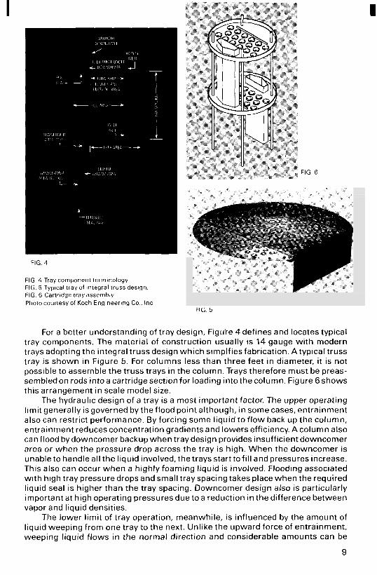
FIG 4
FIG 4 Tray component terminology FIG 5 Typical tray of integral truss design FIG 6 Cartridge tray assembly Photo courtesy of Koch Enq ineer iw Co , Inc
FIG. 5
For a better understanding of tray design, Figuie 4def ines and locates typical tray components. The material of construction usually is 14 gauge with modern trays adopting the integral truss design which simplfies fabrication. Atypical truss tray is shown in Figure 5. For columns less than three feet in diameter, it is not possible to assemble the truss trays in the column. Trays therefore must be preas- sembledon rods intoa cartridgesection for loading intothecolumn. Figure Gshows this arrangement in scale model size.
The hydraulic design of a tray is a most important factor. The upper operating l imit generally is governed by the flood point although, in some cases, entrainment also can restrict performance. By forcing some liquid to f low back up the column, entrainment reduces concentration gradients and lowers efficiency. A column also can flood by downcomer backup when tray design provides insufficient downcomer area or when the pressure drop across the tray is high. When the downcomer is unable to handle all the liquid involved, the trays start to fi l l and pressures increase. This also can occur when a highly foaming liquid is involved. Flooding associated wi th high tray pressure drops and small tray spacing takes place when the required liquid seal is higher than the tray spacing. Downcomer design also is particularly important at high operating pressures due to a reduction in the difference between vapor and liquid densities.
The lower l imit of tray operation, meanwhile, is influenced by the amount of liquid weeping from one tray to the next. Unlike the upward force of entrainment, weeping l iquid flows in the normal direction and considerable amounts can be
9
tolerated before column efficiency is significantly affected. As the vapor rate decreases, however, a point eventually is reached when all the l iquid is weeping and there is no l iquid seal on the tray. This is known as the dump point below which there is a severe drop in efficiency.
SIEVE TRAY The sieve tray is a low cost device which consists of a perforated plate that usually has holes of 3/16 inch to one inch diameter, a downcomer, and an outlet weir. Although inexpensive, a correctly designed sieve tray can be comparable to other styles in vapor and liquid capacities, pressure drop, and efficiency. For flexibility, however, it is inferior to valve and bubble cap trays and sometimes is unacceptable for low liquid loads when weeping has to be minimized.
Depending upon process conditions and allowable pressure drop, the turndown ratio of a sieve tray can vary from 1.5 to 3 and occasionally higher. Ratios of 5 as sometimes claimed can be achieved only when the tray spacing is large, available pressure drop isvery high, l iquid loadings are high, and the system is non-foaming. For many applications, a turndown of 1.5 is quite acceptable.
It also is possible to increase the flexibility of a sieve tray for occasional l ow throughput operation by maintaining a high reboil and increasing the reflux ratio. This may be economically desirable when the l ow throughput occurs for a small fraction of the operating time. Flexibility likewise can be increased by the use of blanking plates to reduce the hole area. This is particularly useful for initial opera- tion when it is proposed to increase the plant capacity after a few years. There is no evidence to suggest that blanked-off plates have inferior performance to unblanked plates of similar hole area.
DUAL FLOW TRAY The dual f low tray is a high hole area sieve tray without a downcomer The liquid passes down through the same holes through wh ich the vapor rises Since no downcomer is used, the cost of the tray is lower than that of a conventional sieve tray
In recent years, use of the dual f low tray has declined somewhat because of difficulties experienced w i th partial Iiquid/vapor bypassing of the two phases, par- ticularly in larger diameter columns The dual f low column also has a veryrestricted operating range and a reduced efficiency because there is no crossflow of l iquid
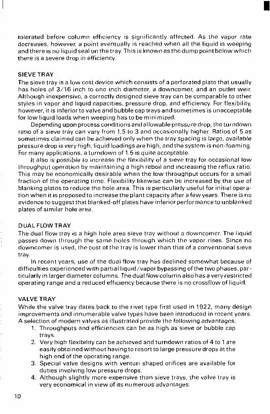
VALVE TRAY While the valve tray dates back to the rivet type first used in 1922, many design improvements and innumerable valve types have been introduced in recent years A selection of modern valves as illustrated provide the following advantages
1 Throughputs and efficiencres can be as high as sieve or bubble cap trays
2 Very high flexibility can be achieved and turndown ratios of 4 to 1 are easily obtained without having to resort to large pressure drops at the high end of the operating range
3 Special valve designs w i th venturi shaped orifices are available for duties involving low pressure drops
4 Although slightly more expensive than sieve trays, the valve tray is very economical in view of its numerous advantages
10
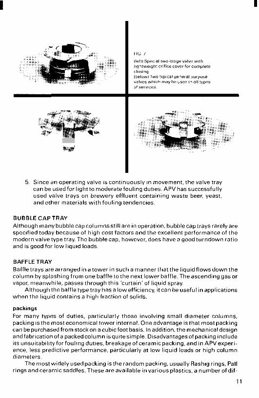
FIG 7
( left) Special two-stage valve w i t h l ightweight ori f ice cover for complete closing (below) Two typical general purpose valves wh ich may be used in al l types of services
5. Since an operating valve is continuously in movement, the valve tray can be used for light to moderate fouling duties. APV has successfully used valve trays on brewery effluent containing waste beer, yeast, and other materials w i th fouling tendencies.
BUBBLE C A P TRAY Although many bubble cap columns still are in operation, bubble cap trays rarely are specified today because of high cost factors and the excellent performance of the modern valve type tray. The bubble cap, however, does have a good turndown ratio and is good for low liquid loads.
BAFFLE TRAY Baffle trays are arranged in a tower in such a manner that the liquid flows down the column by splashing from one baffle to the next lower baffle. The ascending gas or vapor, meanwhile, passes through this 'curtain' of liquid spray.
Although the baffle type tray has a lowefficiency, it can be useful in applications when the liquid contains a high fraction of solids.
packings For many types of duties, particularly those involving small diameter columns, packing is the most economical tower internal. One advantage is that most packing can be purchased from stockon a cubic foot basis. In addition, the mechanical design andfabricationof a packed column isquitesimple. Disadvantagesof packing include its unsuitability for fouling duties, breakage of ceramic packing, and in APV experi- ence, less predictive performance, particularly at low liquid loads or high column diameters.
The most widely used packing is the random packing, usually Rashig rings, Pall rings and ceramic saddles. These are available in various plastics, a number of dif-
1 1
ferent metals and, w i th the exception of Pall rings, i n ceramic materials. Whi le packings i n plastic have the advantage of corrosion resistance, the self-wetting ability of some plastic packing such as fluorocarbon polymers sometimes is poor, particularly in aqueous systems. This considerably increases the HETP when compared w i th equivalent ceramic rings.
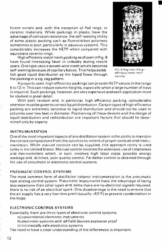
High efficiency metal mesh packing as shown in Fig. 8 have found increasing favor in industry during recent years. One type uses a woven w i re mesh wh ich becomes self-wetting because of capillary forces. This helps estab- lish good liquid distribution as the liquid f lows through the packing in a zig-zag pattern.
FIG 8 Segment of high efficiency metal mesh packing
If properly used, high efficiency packings can provide HETPvalues i n the range 6 t o 1 2 in.Thiscan reducecolumn heights,especiallywhena large numberoftrays is required. Such packings, however, are veryexpensive and each application must be studied in great detail.
Wi th both random and, in particular, high efficiency packing, considerable attention must begiven tocorrect liquid distribution. Certain types of high efficiency packing are extremely sensitive to l iquid distribution and should not be used i n columns over two feet i n diameter. Positioning of these devices and the design of liquid distribution and redistribution are important factors that should be deter- mined only by experts.
I N ST R U M E N TAT1 0 N Oneofthe most importantaspectsof anydistillation system isthe abil ityto maintain the correct compositionsfrom the columns by means of proper controls and instru- mentation. Whi le manual controls can be supplied, this approach rarely is used today in the United States. Manual control involves the extensive use of rotameters and thermometers which, in turn, involves high labor costs, possible energy wastage and, at times, poor quality control. Far better control is obtained through the use of pneumatic or electronic control systems.
P N E U M A T I C C O N T R O L S Y S T E M S The most common form of distillation column instrumentation is the pneumatic type analog control system Pneumatic instruments have the advantage of being less expensive than other types and, since there are no electrical signals required, there is no risk of an electrical spark One disadvantage is the need to ensure that the air supply has a very low dew point (usually -40°F) to prevent condensation in the loops
ELECTRONIC C O N T R O L S Y S T E M S
Essentially, there are three types of electronic control systems. a) conventional electronic instruments b) electronic systems w i th all f ield devices explosion proof c) intrinsically safe electronic systems
The need to have a clear understanding of the differences is important
12
Most disti l lation duties involve at least one flammable l iquid which is being processed i n both the vapor and liquid phases. Since there always is the possibility of a leak of l iquid or vapor, part icularlyfrom pump seals, it is essential for complete safety that there be no source of ignition in the vicinity of the equipment. Whi le many instruments such as controllers and alarms can be located in a control room removed from the process, all local electronic instruments must be either explosion proof or intrinsically safe.
Wi th explosion proof equipment, electrical devices and wir ing are protected by boxes or conduit which will contain any explosion that may occur.
Wi th intrinsically safe equipment, barriers l imit the transmission of electrical energy to such a low level that it is not possible to generate a spark. Since explosion proof boxes and conduits are not required, wir ing costs are reduced.
For any intrinsically safe system to be accepted for insurance purposes, FM (Factory Mutual) or CSA(Canadian Standards Association) approval usually must be obtained. This approval applies to a combination of barriers and field devices. There- fore, when a loop incorporates such instrumentsfrom different manufacturers, it is essential to ensure that approval has been obtained for the combination of instruments.
AUXILIARY E Q U I P M E N T In any distillation system, the design of auxiliary equipment such as the reboiler, condenser, preheaters and product coolers is as important as the design of the column itself
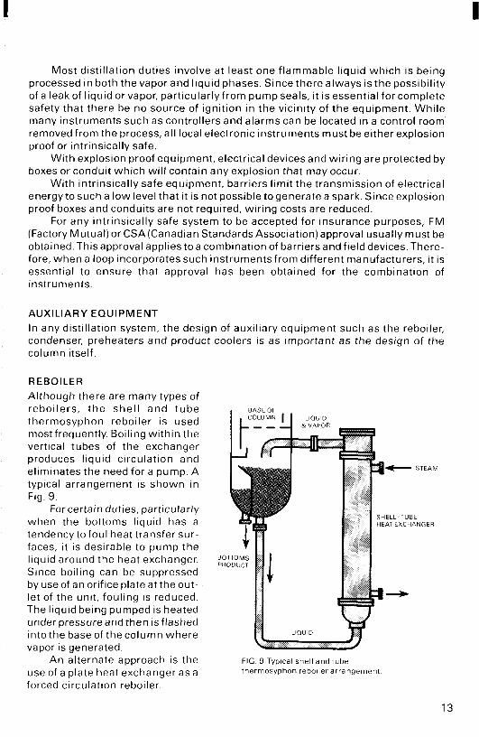
REBOILER Although there are many types of reboi lers, t he she l l and tube thermosyphon reboiler is used most frequently Boiling wi th in the vertical tubes of the exchanger produces l iquid circulation and eliminates the need for a pump A typical arrangement is shown in Fig 9
For certain duties, particularly when the bottoms liquid has a tendency to foul heat transfer sur- faces, it is desirable to pump the liquid around the heat exchanger Since boiling can be suppressed by use of an orifice plate at the out- let of the unit, fouling is reduced The liquid being pumped is heated under pressure and then is flashed into the base of the column where vapor is generated
A n alternate approach is the use of a plate heat exchanger as a forced circulation reboiler
FIG 9 Typical shell and tube thermosyphon reboiler arrangement
13

With this technique, the very high l iquid turbulent f low which is induced within the heat exchanger through the use of multiple corrugated plates holds fouling to a minimum. Meanwhile, the superior rates of heat transfer that are achieved reduce the surface area required for the reboiler.
CONDENSERS Since most distillation column condensers are of shell and tube design, the proces- sor has the option of condensing on either the shell or tube side. From the process point of view, condensation on the shell side is preferred since there is less subcool- ing of condensate and a lower pressure drop is required. These are important factors in vacuum duties. Furthermore, w i th cooling water on the tube side, any fouling can be removed more easily.
Tube side condensation, on the other hand, can be more advantageous whenever process f luid characteristics dictate the use of more expensive, exotic materials. Capital cost of the unit then may be cut by using a carbon steel shell.
PR E H E ATE R S / C 0 0 LE R S The degree to which fluids are aggressive to metals and gasketing materials gener- ally determines the selection of plate or shell and tube preheaters and product coolers.
If f luids are not overly aggressive toward gasket materials, a plate heat ex- changer is an extremelyefficient preheater since a veryclose temperature approach may be achieved. Added economy is realized by using heat from the top and bottoms product for all necessary preheating.
While plate type units can be supplied w i th compressed asbestos fiber gaskets, very aggressive duties normally are handled in a number of tubular exchangers arranged in series to generate a good mean temperature difference. The use of multiple tubular units obviously is more expensive than a single plate heat exchanger but is unavoidable for certain solutions such as aromatic compounds.
VENT CONDENSER It is normal practice on distillation systems to use a vent condenser after the main condenser to minimize the amount of volatiles being driven off into the atmosphere. Usuallyof the shell and tube type, the vent condenser wi l l have about one-tenth the area of the main unit and wi l l utilize a chilled water supplytocool the non-conden- sible gases to about 45-5OoF.
PUMPS Since most distillation duties involve fluids that are highly flammable and have a low flash point, it is essential that explosion-proof (Class 1, Group D, Division 1) pump motors be supplied. Centrifugal pumps generally are specified since they are reliable and can provide the necessary head and volumetric capacity at moderate costs.
14
I
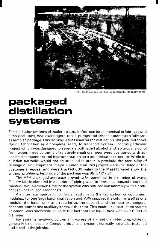
FIG 10 Packaged dist i l lat ion system during fabrication
packaged distiIIation systems For distillation systems of moderate size, it often can be economical to fabricate and supply columns, heat exchangers, tanks, pumps and other elements as a ful ly pre- assembled package.This technique was used for the distillation unit pictured above during fabrication as a complete, ready to transport system. For this particular project which was designed to separate both ethyl alcohol and is0 propyl alcohol from water, three columns of relatively small diameter were positioned w i th as- sociated components and instrumentation on a prefabricated structure. While in- sulation normally would not be supplied in order to preclude the possibility of damage during shipment, major elements on this project were insulated at the customer's request and were trucked 600 miles to the Massachusetts job site without problems. Final size of the package was 65' x 12' x 8'.
The APV packaged approach proved to be beneficial in a number of ways. Factory fabrication and installation of piping was far more economical than field finishing whi le erection t ime for the system was reduced considerably with signifi- cant savings in local labor costs.
A n alternate approach for IaFger systems is the fabrication of equipment modules. For one large batch distillation unit, APV supplied the column itself as one module, the batch tank and reboiler as the second, and the heat exchangers, decanter, pumps and auxiliary items as the third. This modular construction prior to shipment was successful despite the fact that the batch tank was over 8 feet in diameter.
For systems involving columns in excess of six feet diameter, prepackaging generally is not feasible. Components of such systems normally have to be installed and piped at the job site.
15

typical installations fuel alcohol
To provide the 199 proof ethyl alcohol required for blending with gasoline during the production of gasohol, a complicated distillation system is needed. A minimum of a three column system is required since ethyl alcohol forms an azeotrope with water. This azeotrope has to be broken in a separate column through the use of an entraining agent which subsequently is recovered for reuse.
The simplified flow diagram shown below represents the APV power alcohol technique. This system uses double effect distillation so that heat can be cascaded to the reboiler on the dehydration still. Due to this double effect approach, steam consumption is as low as 16 Ibs/gallon of alcohol product with a feed beer stream containing 10% by volume alcohol. The design of the beer still is particularly important and, since the feed has a tendency to foul the metal surfaces, APV offers tray columns.
For certain duties, APV can provide a forced circulation Paraflow plate heat exchanger for the reboiler. This arrangement minimizes fouling and eliminates the need for direct steam injection which dilutes the stillage and causes more effluent. This is an important feature of the design.
APV has operating experience with a number of different entraining agents including benzene, isopropyl ether and cyclohexane.
1DtGASSER 2 DEGASSER JREBOILER 4 FEED S E E R 6DEHYDRATlOH 7CONUENSEW 8FINAL PPREHEATING 1OCONDENSER CONDENSER PREHEATER STILL COLUMN REBOILER CONDENSER CONDENSER
11 DECANTER 12 VENT l3ENTAAtNER 14 REBOILER lSALEOHOL CONDENSER RECOVERY COOLER
COLUMN
16
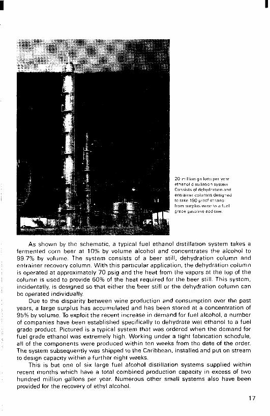
20 million gallons per year ethanol distillation system Consists of dehydration and entrainer columns designed to take 190 proof ethanol from surplus wine to a fuel grade gasoline additive
As shown by the schematic, a typical fuel ethanol distillation system takes a fermented corn beer at 10% by volume alcohol and concentrates the alcohol to 99.7% by volume. The system consists of a beer still, dehydration column and entrainer recovery column. With this particular application, the dehydration column IS operated at approximately 70 psig and the heat from the vapors at the top of the column is used to provide 60% of the heat required for the beer still. This system, incidentally, is designed so that either the beer still or the dehydration column can be operated individually.
Due to the disparity between wine production and consumption over the past years, a large surplus has accumulated and has been stored at a concentration of 95% by volume. To exploit the recent increase in demand for fuel alcohol, a number of companies have been established specifically to dehydrate wet ethanol to a fuel grade product. Pictured is a typical system that was ordered when the demand for fuel grade ethanol was extremely high. Working under a tight fabrication schedule, all of the components were produced within ten weeks from the date of the order. The system subsequently was shipped to the Caribbean, installed and put on stream to design capacity within a further eight weeks.
This is but one of six large fuel alcohol distillation systems supplied within recent months which have a total combined production capacity in excess of two hundred million gallons per year. Numerous other small systems also have been provided for the recovery of ethyl alcohol.
17


I methanol recycled
Designed to recover methanol from solvent laden air, this absorber and distillation system uses water to continuously assimilate up to 95%of the MeOH contained in an airstream of up to 9000cfm which originates in a drying operation. After absorp- tion is carried out in a 52‘ high by 6‘ diameter column equipped wi th valve trays, 26,000 Ibs/hr of enriched water is passed through a regenerative Paraflow plate preheater to the adjacent 75’by 3’6” diameter distillation column. Here, alcohol in the feed is stripped down to .02% w/w. While bottoms are recirculated to the ab- sorber, enriched alcohol above the feed point is rectified in the upper section of t he distillation column.
19

antibiotic solvents
Engineering personnel give final check to IPA system while xylene column in the background awaits shipment
For a major project involving the production of a full range of antibiotics, APV has contracted to engineer and furnish nearly a score of distillation columns w i th all the auxiliary equipment needed to recover eight basic solvents from 2 8 different sources. Included are butyl acetate, butanol, xylene, acetone, triethylamine, iso- propyl alcohol, toluene, and methyl isobutyl ketone (MIBK), many with two to five points of origin and the latter from eight separate sources. Each wi l l be processed individually to eliminate any possibility of cross-contamination of the antibiotics.
After a year of laboratory tests, more than 16,000 hours of engineering work and 14 volumes of specifications, the fabrication of 19 columns, nine large solvent reboil tanks and nearly 100 plate or tubular heat exchangers was undertaken. To this was added scores of pumps, miles of piping, and system control modules in- volving close to 1500 valves, indicators and controllers. Several pieces of 78-foot length and three to four feet in diameter were shipped as integral units while the largest column measuring 106 feet by 3 feet in diameter was transported in two sections. Components are being installed in 22 bays wi th in a 400 by 33 foot struc- ture wi th 15 feet high firewalls between solvent modules.
20

flue gas desulfurization
As an integral part of an experimental pollution control program, APV is providing SIX sodium carbonate regeneration columnsfor the Rockwell International Aqueous Carbonate system to be installed at a large utility power station. This demonstration plant isdesigned to reduce the r iskof 'acid rain'caused by sulfur dioxide emissions produced when coal is burned for electric power generation.
Under the experimental process, f lue gas from the power plant is diverted to a spray dryer scrubber where the sulfur dioxide reacts with an atomized sodium carbonate solution. This produces a fine powder essentially consisting of sodium sulfite. The gas clean subsystem is designed to remove 90% or more of the SO2 from approximately 300,000 scfm of f lue gases and is expected to be effective w i th gases containing from 200 to more than 2000 ppm of sulfur dioxide.
For the adjacent regeneration subsystem, APV engineered and fabricated six columns which range from 3 to 4 feet in diameter by 68 to 70 feet high. These include a precarbonator, two crystallizers and carbonators (one each on-line, one spare), and a decomposer.
In this phase of the process, the dry spent absorbent collected i n the gas cleaning subsystem IS reduced w i th coke and then iswater quenched. The resultant process 'green liquor' is charged to the APV precarbonator where contact with a gas stream induces a series of exothermic reactions. After f i l tration and cooling, the partially precarbonated liquor is pumped to the crystallizer where contact w i th COz-rich gas from the carbonator produces a sodium bicarbonate slurry. Wi th solids content reduced by filtration, this solution is further crystallized in the car- bonator before being fed to the final column, the decomposer. Here, the sodium bicarbonate is thermallydecomposed to a sodium carbonate solution which is stored for eventual reuse in scrubbing more f lue gas. Meanwhile, the hydrogen sulfide gas which evolves during the carbonation cycle is converted to elemental sulfur in a conventional Claus plant.
The regeneration subsystem is sized to produce 12 tons per day of elemental sulfur and regenerate 5000 Ibs/hr of sodium carbonate for reuse in SOz removal.
Trays are positioned prior to closing the column 21
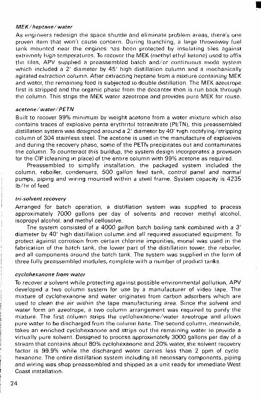
MEK/heptane/water
As engineers redesign the space shuttle and eliminate problem areas, there's one proven item that won't cause concern. During launching, a large throwaway fuel tank mounted near the engines has been protected by insulating tiles against extremely high temperatures. To recover the MEK (methyl ethyl ketone) used to affix the tiles, APV supplied a preassembled batch and/or continuous mode system which included a 2' diameter by 45' high distillation column and a mechanically agitated extraction column. After extracting heptane from a mixture containing MEK and water, the remaining feed is subjected to double distillation. The MEK azeotrope first is stripped and the organic phase from the decanter then is run back through the column. This strips the MEK water azeotrope and provides pure MEK for reuse.
acetone/water/PETN Built to recover 99% minimum by weight acetone from a water mixture which also conrains traces of explosive penta erythritol tetranitrate (PETN), this preassembled distillation system was designed around a 2' diameter by 40' high rectifying/stripping column of 304 stainless steel. The acetone is used in the manufacture of explosives and during the recovery phase, some of the PETN precipitates out and contaminates the column. To counteract this buildup, the system design incorporates a provision for the CIP (cleaning in place) of the entire column with 99% acetone as required.
Preassembled to simplify installation, the packaged system included the column, reboiler, condensers, 500 gallon feed tank, control panel and normal pumps, piping and wiring mounted within a steel frame. System capacity is 4235 Ib/hr of feed.
tri-solvent recovery
Arranged for batch operation, a distillation system was supplied to process approximately 7000 gallons per day of solvents and recover methyl alcohol, isopropyl alcohol, and methyl cellosolve.
The system consisted of a 4000 gallon batch boiling tank combined with a 3' diameter by 40' high distillation column and all required associated equipment. To protect against corrosion from certain chlorine impurities, monel was used in the fabrication of the batch tank, the lower part of the distillation tower, the reboiler, and all components around the batch tank. The system was supplied in the form of three fully preassembled modules, complete with a number of product tanks.
cyclohexanone from water
To recover a solvent while protecting against possible environmental pollution, APV developed a two column system for use by a manufacturer of video tape. The mixture of cyclohexanone and water originates from carbon adsorbers which are used to clean the air within the tape manufacturing area. Since the solvent and water form an azeotrope, a two column arrangement was required to purify the mixture. The first column strips the cyclohexanone/water azeotrope and allows pure water to be discharged from the column base. The second column, meanwhile, takes an enriched cyclohexanone and strips out the remaining water to provide a virtually pure solvent. Designed to process approximately 3000 gallons per day of a stream that contains about 80% cyclohexanone and 20% water, the solvent recovery factor is 99.9% while the discharged water carries less than 2 ppm of cyclo- hexanone. The entire distillation system including all necessary components, piping and wiring was shop preassembled and shipped as a unit ready for immediate West Coast installation.
24

acetone from water
For a pharmaceutical process, APV has provided a complete distillation system designed to recover up to 99 6% of acetone from water which also contains traces of ethanol and MlBK System components include a 55' high by 3'3" diameter column equipped with valve trays, main and vent condensers, a forced circulation Series R57 Paraflow plate reboiler, accumulator vessel, ful l instrumenta- tion, and a three section 'Junior' Paraflow to preheat feed regenera- tively with top product and column bottoms The design also includes multiple take-off points to prevent MlBK and/or ethanol buildup Feed rate is 3 8 0 gallons/hr of solvent and water mixture
deactivating nitro
In a somewhat unusual application, an APV sieve tray scrubber is in- corporated into the process for manu- facturing small fuel pelletsfor missile propulsion. This 20' high by 4' di- ameter unit was designed to scrub
acetoneand ethanol w i th causticsoda i n the presence of traces of nitro- glycerin. The acetone and ethanol are removed from an air f low of up to 5500cfm originating in the propellant drying room while the caustic soda absorbs and denitrates the trace quantities of nitro.
Freon/MCF distillation
Utilizing an APV batch distillation system, a producer of printed circuits currently is separating a two com- ponent mixture of Freon TF and methyl chloroform wi th recoveries respectively of better than 98% and 90% by volume. The 28' high by 12" diameter distillation column equipped w i th stainless steel mesh packing is f itted to a 1450 gallon batch tank, a solvent holding tank, reboiler, and system controls on a platform only 12' long and 8' wide. Feed rates are approximately 1200 gallons per day, double the processing capability of a similar packaged system which was sup p I i ed previous I y.
25
a comparison between benzene and is0 propyl ether for use in
the dehydration of is0 propyl alcohol
In the pharmaceutical industry, it often is necessary to recover solvents by distillation both to save costs and to reduce the volume of effluents. Since one company may use a number of different solvents, frequently in small quantities, it i s essential that the distil- lation system installed for recovery operations be very flexible.
A typical case may be seen at Scientific Protein Laboratories (SPL) of Waunakee, Wisconsin. This small manufacturer of specialty pharmaceuticals currently i s recovering acetone, methanol and i s 0 propyl alcohol ((PA) from water mixtures. The distillation system, designed and fabricated by APV, easily handles the various duties involved, is economical to operate, and represents a moderate capital investment.
IPA dehydration It i s a relatively straightforward engineering task to design either a batch or continuous distillation system to separate both acetone and methanol from water or to concentrate IPA to the azeotrope composition. The more volatile components can be collected at the top of the column with the reflux ratio being controlled by monitoring the temperature a t an adjacent point. This controls the product take-off rate. I f there are sufficienttrays in the column, the required separation will be achieved.
Dehydration of the IPA/water azeotrope, however, i s more difficult since it i s neces- sary to break the azeotrope. This was done at SPL in a continuous operation that used an entrainer to form a ternary azeotrope. The duty was to dehydrate 4.5 GPM of I PA/water azeotrope containing 12.6% w/w water. The product was to contain less than 0.1% w/w water and less than 0.1 % w/w of the entrainer.
early experimental work Although data were abundantly available on the dehydration of ethanol using benzene as entrainer ( I ) , there was very l i t t le information to be had some years ago on the dehydra- tion of IPA. I t therefore was decided to carry out t e s t work on a small laboratory column to determine the optimum design having minimum energy requirements. Rough calcula- tions indicated that almost 30 theoretical trays would be required so the test unit, a 1 'A'' diameter column with metal mesh packing, was se t upwith the equivalent of 30 theoret- ical trays. The overall packed height was 60".
The t e s t column was operated in continuous mode with sufficient benzene a t the top to hold the temperature close to that of the ternary azeotrope boiling point. The opti- mum feed point was found to be three theoretical trays from the column top. Higher feed points reduced the efficiency of the formation of the t e r n q azeotrope and caused a reduction in the water removal rates for a constant reboil rate.
26
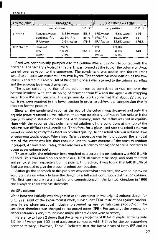
I w ENTRAINER
BINARY
T E R N A R Y
I BENZENE
composition B.P. O F
Benzene/water 8.83% water 156.6 BenzenellPA 33.3% IPA 161.5 IPA/water 12.6% water 1 76.5
Benzene 73.8% I PA 18.7% 151.7 Water 7.5%
- I S 0 PROPYL E T H E R
~
composition B.P. O F
IPE/water 4.5% water 144 IPE/IPA 16.3% IPA 151 IPA/water 12.6% water 176.5
IPE 89.0% I PA 6.0% 143 Water 5.0%
Feed was continuously pumped into the column where it came intocontact with the benzene. The ternary azeotrope (Table 1) was formed a t the top of the column and was carried over as vapor to the condenser. The condensate was cooled and the resultant two-phase liquid was decanted into two layers. The theoretical composition of the two layers i s charted in Table 2. All of the organic phase was returned to the column as reflux and the aqueous layer was discharged.
The lower stripping portion of the column can be considered as two sections: the bottom involved with the stripping of benzene from IPA and the upper wi th stripping water from IPA and benzene. The experimental work confirmed that about 27 theoret- ical trays were required in the lower section in order t o achieve the composition that i s required for the product.
Since all the condensed vapor a t the top of the column was decanted and only the organic phase returned to the column, there was no clearly defined reflux ratio as i s the case with most distillation operations. Additionally, since the reflux was not in equilib- rium with the vapor a t that point, any calculation of the conditions a t the top of the column was difficult and unreliable. Therefore, for a given feed rate the reboil rate was varied in order to study the effect on product quality. As the reboil rate was reduced, two phenomena would occur. When insufficient azeotrope was being produced, the removal rate of the water was less than required and the water content of the bottom product increased. A t low reboil rates, there also was a tendency for higher benzene contents to occur a t the column bottom.
Theoretically, the minimum heat required to operate the test column was 600 Btu/lb of feed. This was based on no heat losses, 100% decanter efficiency, and both the feed and reflux at their respective boiling points. In practice, it was found that 840 Btu/lb of feed was needed to give the proper product composition.
Although the approach t o this problem was somewhat empirical, the work did provide accurate data on which to base the design of a full scale continuousdistillation column. The first such column was installed and commissioned in the United Kingdom in 1966 and always has operated satisfactorily.
the SPL column
While benzene initially was designated as the entrainer in the original column design for SPL as a result of the experimental work, subsequent FDA restrictions against carcino- gens in the pharmaceutical industry prevented i t s use for full scale production. The entrainer therefore was changed t o i s 0 propyl ether (IPE). Fortunately, the process for either entrainer i s very similar so no major plant revisions were necessary.
Reference t o Table 2shows that the ternary azeotrope of IPA/I PE/water entrains only 3.9 Ibs of water per 100 Ibs of azeotrope compared with 6.2 Ibs for the corresponding benzene ternary. However, Table 3 indicates that the latent heats of both IPE and i t s
27
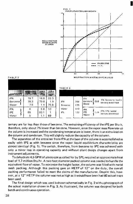
FIG. 1 VAPOR LlOUlO EQUILIBRIUM DATA
MOLE FRACTION BENZENEOR IPE
IN VAPOR
TABLE 2
I PA 18.7 18.8 1 $;:ne] I 7;:; 179.8 1.4 ti" 1 89
MOLE FRACTION: BENZENEOR IPE IN LlOUlD
I 286 I Etnzene 1 IPA/benzene/water 258 ternaryazeotrope
Benzene 175 Water I L I
Water IPE 1 :l: [ 1 ,74 IPA/IPE/water
ternary azeotrope Water
ternary are far less than those of benzene. The entraining efficiency of the IPE per Btu is, therefore, only about 7% lower than benzene. However, since the vapor mass flowrate up the column i s increased and the condensing temperature i s lower, there i s an extra load on the column and condenser. This will slightly reduce the capacity of the column.
The separation of the entrainer from IPAat the base of the column is accomplished as easily with IPE as with benzene since the vapor liquid equilibrium characteristics are almost identical (Fig. 1). The switch, therefore, from benzene to IPE wasachievedwith only a minor loss in operating capacity and without plant design changes apart from instrument adjustments.
To dehydrate 4.5 GPM of azeotrope as called for by SPL required an approximate heat load of 1.7-million Btu/hr. A two foot diameter packed column was needed to handle the equivalent flow of vapor. To minimize the height factor, the column was filled with metal mesh packing. Although this packing gave an HETP of 12" on the duty, the overall packing performance failed to meet the claims of the manufacturer. Despite this, how- ever, a t a 12" HETP the column was not as high as it would have been had 60 actual trays been used.
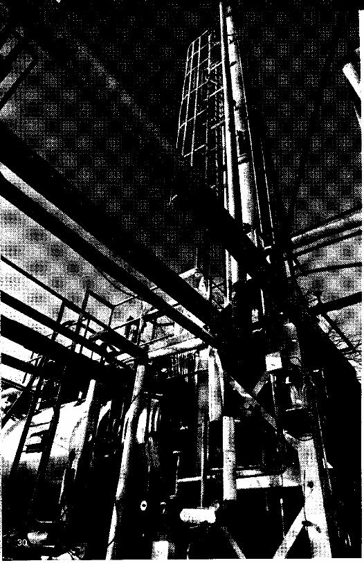
The final design which was used is shown schematically in Fig. 2 with a photograph of the actual installation shown in Fig. 3. As illustrated, the column was designed for both batch and continuousoperation.
28

batch operation When operated in batch mode, 2500 gallons of either IPA/water, methanol/water or acetone/water were pumped into the batch tank. A t startup, the column wasallowed to come to equilibrium on total reflux. When the temperature a t 'A'attained a value close to that of either the pure product or the azeotrope boiling point, the column was switched to automatic control. The product was drawn off through valve 'V- l 'w i th the valve being set according to the temperature a t the 'A' point. As this temperature increased, the automatic controls started to reduce the product removal rate. This increased the reflux ratio which maintains the required temperature a t 'A'. As the distillation proceeded, the concentration of the volatile component in the tank decreased and eventually, the tem- perature a t 'A' no longer could be maintained even on total reflux. A t this stage, the distillation was complete. Residual solvent in the tower was boiled off a t zero reflux ratio to a ta i l s tank and the contents of the batch tank were dumped to the drain. Typical of a batch distillation operation, this procedure combined both flexibility and simplicity.
continuous operation with benzene as entrainer The alternate operation of this column for the dehydration of the IPA/water azeotrope was more complex. This operation was carried out continuously. A t the start of a run, about 500 gallons of IPA/benzene mixture were charged to the batch tank. The column then was started up on total reflux and when the IPA/benzene azeotrope temperature was achieved a t the topof the column,feed gradually was pumped to the column a t a low rate of 2 GPM. The temperature a t 'A'gradually fell to the ternary azeotrope value of about 152°F and at this point, the condensed top product was diverted through the two stage cooler into the decanter. The organic phase from the decanter was pumped through the regenerator section of the heat exchanger back to the top of the column as reflux. The aqueous phase was pumped to storage for subsequent processing back to the azeotrope in a batch operation.
As soon as the aqueous phase was separating in the decanter, the feed was increased to
29
4.5 GPM. The level of the anhydrous IPA in the batch tank was maintained low under level control and the product was pumped through a cooler to storage.
I t was necessary to maintain a small flow of benzene to the column to compensate for losses. This makeup of the benzene was controlled from a measurement of the tempera- ture a t 'A . I t was found that i f the temperature at 'A' increased above 157"F, the liquid condensate failed to separate into two phases. This was corrected by adding benzene to the column and bringing the temperature down to about 152" F. This temperature, there- fore, was used to control the addition of benzene to the column. As long as the steam flow was a t 840 Btu for every pound of feed, control of the column was relatively simple.
At the end of the run, the benzene was recovered from the top of the column in the form of benzene/lPA azeotrope. This was stored for use a t the next startup.
continuousoperation with IPE as entrainer Similar operation was achieved using IPE as entrainer. The only significant differencewas that the azeotrope temperature was 143°F.
metal mesh packing performance The metal mesh packing used as the mass transfer device did enable the column to be shorter in height than would have been required with trays. However, the performance of this packing did fall considerably below expectations. While claims of 4" t o 8" for the height equivalent t o a theoretical plate (HETP) had been made, the column was giving over 12" HETP. The 2 f t diameter column a t SPL was larger in diameter than other columns that APV had tested with mesh packing. In addition, the column wasarranged with 12' intervals between liquid redistribution points.
I t appears, therefore, that on an industrial size column with conventional liquid distribution and redistribution devices, an HETP of less than 12" probably i s difficult to achieve. With small columns of I O " diameter or less having good and frequent liquid distribution, it may be possible to achieve such low HETPvalues.
At a 12" HETP, the cost of using such packing is more expensive than using trays when trays are rated as 50% efficient. Therefore, unless height is o f prime importance, APV normally would not use metal mesh packings for columns of 12"diameter and larger.
practical conclusions During the startup ot the column, a number of very important conclusions were reached mainly as a result of practical experience.
Good management of the solvent tanks was essential. For example, small amounts of methanol or acetone in the IPA reduced the efficiency of the azeotrope distillation. I t was therefore essential t o remove all high volatiles before starting the azeotropicdistilla- tion. It was even more important to ensure that high volatile impurities did not become mixed with the IPAduringstorage.
Since the decantation of the two phase azeotrope was best achieved a t IOO"F, it was necessary to cool the condensate and then reheat the reflux to i t s boiling point. In many distillation operations, it i s not necessary to reheat the reflux but in this application where the reflux is of a different composition than the distillate, cold reflux reduces the dehydration capacity of the column.
I t also was a useful feature t o have sight glasses on both the decanter and on the feed line to the decanter. Those visual aids were essential during startup in order to set up the decanter to give maximum efficiency.
Ref ere nces 1. Guinot, H -Clark, F.W.
Trans. Inst. Chem. Engrs. (London) 1938,16,187 31
the
bre W ry eff
In recent years there has been a considerable tighte ng of restrictions governing
of such regulations coupled w i th technical advancements in the efficiencyof waste treatment plants has improved many waterways, more stringent restrictions n o w are being imposed to further restore river water quality. One industry feeling the effects of this continuing program is the brewing industry, where a significant amount of l iquid effluent has to be treated for BOD reduction before it can be discharged to sewer.
Brewery effluent contains a mixture of suspended solids, soluble solids, ethyl alcohol, water and small quantitiesof other volatiles. Since the ethyl alcohol contrib- utes significantly to the BOD of the effluent, and since ethyl alcohol is a valuable product in concentrated form, it is advantageous to remove this effluent, purify it and produce a salable l iquid which wi l l help to offset the costs of effluent treatment. Most brewery effluent is a mixture of waste beer, washings and yeast. Normally this l iquid containsfrom 2%v/vto 4%v/vethyl alcohol together with minor amountsof other volatiles such as aldehydes.
In conjunction w i th some breweries, APV has developed a number of tech- niques for the treatment of these waste products and also for the recovery of the alcohol. This paper discusses alcohol recovery and points out some of the difficulties encountered and techniques used for overcoming these problem areas.
the discharge of liquid effluents in North American in 1 stry. While the enforcement
ETHYL ALCOHOL Ethyl alcohol is a colorless l iquid (SG 0.79)with very little aroma. It is totally miscible w i th water and can be partially separated from water by distillation. It does, however, form an azeotrope w i th water. This azeotrope, or constant boiling mixture as it is sometimes called, boils at 78.15"C and consists of 89.43% molar alcohol. It is pos- sible to concentrate the alcohol to 100% purity but this is diff icult since it involves breaking the azeotrope.
Alcohol, both as its azeotropic composition and at 100% purity, is a valuable product. It can be used as a chemical raw material, in the pharmaceutical industry, for food products, and as a fuel.
32

I
POSSIBLE RECOVERY TECH N IQUES
the column/reboi ler system As illustrated by the Figure 1 schematic, one method of alcohol stripping centers around the utilization of a single free standing distillation column equipped w i th the proper number of trays. Com- pleting the system isa simpledegassing vessel, plate reboiler, condenser, pumps and piping.
In a typical installation, waste beer received at the alcohol recovery area is initially heated and flashed into the de- gassing vessel. This serves to purge the alcoholic stream of carbon dioxide which would choke thedisti l lation column wi th foam and completelydisrupt the distilla- t ion and heat transfer efficiencies.
The degassed stream, which con- tains water and alcohol plus suspended sludge and yeast solids, is fed into the distillation column. As the mixture fills each tray i n its f low down the column, vapor generated by the Paraflow plate heat exchanger reboiler at the base of the still, rises and bubbles through the l iquid on each tray. Since the alcohol in the feed is more volatile than the water and most other components, it r iseswith and progressively enriches the vapor at each successive tray. This action pro- duces a top distillate containing 70% to 95% v/v alcohol depending upon the number of trays ir! the column and the FIG 2 Two column system
reflux ratio being used. This alcohol is drawn off while the still bottomsof water and solids are discharged to the by-product evaporator. The sti l l bottoms contain less than 0.02% v/v alcohol.
In those instances where building or local codes impose height limitations, a system incorporating two shorter distillation columns can be used w i th comparable results. This variation, as shown in Figure 2, produces topsof 70%v/v alcohol in the stripping column with the discharge being fed to an adjacent rectifying column where the alcohol concentration is increased to 95%v/v. A t this level, it is suitable for sale as an industrial solvent. Distillate at 70%v/v, incidentally, will sustain combustion, and if alcohol recovery is not required, may be mixed w i th fuel for easy disposal by
33

FIG 3 Multiple patterned plates are positioned and then compressed within typical Paraflow preheaters
burning in a grains dryer. The bottoms containing water, solids and no more than .02%v/valcohol are combined w i th non-alcoholic effluent, concentrated and either sold separately as a syrup or mixed w i th spent grains for subsequent drying and disposal as a feedstuff.
A number of problems exist in the processing of these effluent streams. One major difficulty is that the effluent liquidsfoul the heat transfer surfaces. In order to prevent foaming in the distillation column, the waste feed has to be heatedto 220°F or higher and then flashed into a degassing vessel which drives off the carbon dioxide and reduces the foaming tendencies. Unfortunately, it is diff icult to heat the process fluid above 1 8OoF because of problems of fouling, particularly w i th certain of the effluent streams. Fouling can, however, be minimized by carefully mixing the effluent streams prior to the preheater to ensure that none of the high fouling materials are present in a large concentration. In addition, the preheaters used are Paraflow Plate Heat Exchangers similar to that shown in Figure 3. These Paraflow plate heat exchangers are less susceptible to fouling than many other types of heat exchangers, since the plate corrugations enhance the l iquid turbulence which assists i n shearing the foul ing depositsoff thesurface. Theyareeasilycleaned-in- place and can be readilyopened if the fouling becomes too bad. Generally, even w i th careful operation, for most applications, the heat exchangers wi l l have to be in-place cleaned at least every two weeks.
Surprisingly, f ield operations showthat these very high fouling fluids have not affected the efficient operation of the column trays. Every few months the trays are cleaned-in-place and at the same t ime are visually inspected. Fouling has not been a problem, probably because of the choice of valve trays for the mass transfer device. The small valves in the holes on the trays are continually moving up and
34

I 4%
d o w n and the re is a lso some rotation. This helps prevent the buildup of foulant in the areas around the holes.
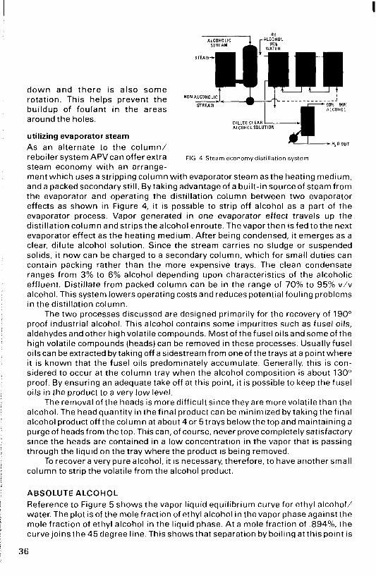
utilizing evaporator steam As an alternate to the column/ reboiler system APVcan offer extra steam economy wi th an arranqe-
ALCOHOLIC
STEAM-
- - - - - - - - - - - - - - 90% ~ 95% ALCOHOL
ALCOHOL SOLUTION DILUTE CLEAR
H,O OUT
STREAM
FIG 4 Steam economydistillation system
ment which uses a stripping column wi th evaporator steam as the heating medium, and a packed secondary still. By taking advantage of a bui l t- in source of steam from the evaporator and operating the distillation column between two evaporator effects as shown i n Figure 4, i t is possible to strip off alcohol as a part of the evaporator process. Vapor generated in one evaporator effect travels up the disti l lation column and strips the alcohol enroute. The vapor then is fed to the next evaporator effect as the heating medium. After being condensed, it emerges as a clear, dilute alcohol solution. Since the stream carries no sludge or suspended solids, it n o w can be charged to a secondary column, which for small duties can contain packing rather than the more expensive trays. The clean condensate ranges from 3% to 6% alcohol depending upon characteristics of the alcoholic effluent. Disti l late from packed column can be in the range of 70% to 95% v/v alcohol. This system lowers operating costs and reduces potential fouling problems i n the distillation column.
The two processes discussed are designed primarily for the recovery of 190" proof industrial alcohol. This alcohol contains some impurities such as fusel oils, aldehydes and other high volatile compounds. Most of the fusel oils and some of the high volatile compounds (heads) can be removed in these processes. Usually fusel oils can be extracted by taking off a sidestream from one of the trays at a point where it is known that the fusel oils predominately accumulate. Generally, this is con- sidered to occur at the column tray when the alcohol composition is about 130" proof. By ensuring an adequate take off at this point, i t is possible to keep the fusel oils in the product to a very l o w level.
The removal of the heads is more diff icult since they are more volatile than the alcohol. The head quantity i n the final product can be minimized by taking the f inal alcohol product off the column at about 4 o r 5 trays belowthe top and maintaining a purge of heads from the top. This can, of course, never prove completelysatisfactory since the heads are contained in a low concentration in the vapor that is passing through the liquid on the tray where the product is being removed.
To recover a verypurealcohol; it is necessary, therefore, to have another small column to strip the volatile from the alcohol product.
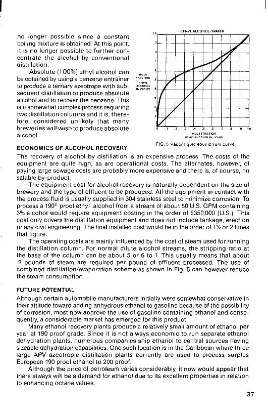
ABSOLUTE ALCOHOL Reference to Figure 5 shows the vapor l iquid equilibrium curve for ethyl alcohol/ water. The plot is of the mole fraction of ethyl alcohol in the vapor phase againstthe mole fraction of ethyl alcohol in the l iquid phase. A t a mole fraction of .894%, the curve joins the 45 degree line. This shows that separation by boiling at this point is
3 6
ETHYL ALCOHOL/WATER
no longer possible since a constant boiling mixture is obtained. At this point, i t is no longer possible to further can- centrate the alcohol by conventional distillation.
Absolute (100%) ethyl alcohol can be obtained by using a benzene entrainer to produce a ternary azeotrope with sub- sequent distillation to produce absolute alcohol and to recover the benzene. This is a somewhat complex process requiring two distillation columns and i t is, there- fore, considered unlikely that many breweries will wish to produce absolute 0 .1 2 .3 4 .5 .e .I .8 9
9
8
7
.S
;;z;g ,~
3
2
?
MOLE FRACTION alcohol. ETHYL ALCOHOLIN LIQUIO
FIG 5 Vapor liquid e q u i l i b r i u m c u r v e ,
ECONOMICS OF ALCOHOL RECOVERY The recovery of alcohol by distillation is an expensive process. The costs of the equipment are quite high, as are operational costs. The alternates, however, of paying large sewage costs are probably more expensive and there is, of course, no salable by-product.
The equipment cost for alcohol recovery is naturally dependent on the size of brewery and the type of effluent to be produced. All the equipment in contact with the process fluid is usually supplied in 304 stainless steel to minimize corrosion. To process a 190' proof ethyl alcohol from a stream of about 50 U.S. GPM containing 3% alcohol would require equipment costing in the order of $350,000 (U.S.). This cost only covers the distillation equipment and does not include tankage, erection or any civil engineering. The final installed cost would be in the order of 1% or 2 times that figure.
The operating costs are mainly influenced by the cost of steam used for running the distillation column. For normal dilute alcohol streams, the stripping ratio at the base of the column can be about 5 or 6 to 1. This usually means that about .2 pounds of steam are required per pound of effluent processed. The use of combined distillation/evaporation scheme as shown in Fig. 5 can however reduce the steam consumption.
FUTURE POTENTIAL
Although certain automobile manufacturers initially were somewhat conservative in their attitude toward adding anhydrous ethanol to gasoline because of the possibility of corrosion, most now approve the use of gasoline containing ethanol and conse- quently, a considerable market has emerged for this product.
Many ethanol recovery plants produce a relatively small amount of ethanol per year at 190 proof grade. Since it is not always economic to run separate ethanol dehydration plants, numerous companies ship ethanol to central sources having sizeable dehydration capabilities. One such location is in the Caribbean where three large APV azeotropic distillation plants currently are used to process surplus European 190 proof ethanol to 200 proof.
Although the price of petroleum varies considerably, it now would appear that there always will be a demand for ethanol due to its excellent properties in relation to enhancing octane values.
37
I
the production of
near and law alcohol beer Although near beer wi th its very low or even zero alcohol content has been available for a number of years, it is only recently that there has been a substantial increase in the demand for this product.
Retaining all the organoleptic qualities of more conventional brews, near beer looks, tastes and smells like beer but does not have its disruptive side effects. These positive attributes have helped the product gain favor among certain Moslem nations in which alcohol is banned while in many other countries that impose very severe penalties for alcohol related driving violations, the sale of near beer has shown dramatic growth. Moreover, wi th the ever increasing concern in the United States over highway fatalities and with the passage and strict enforcement of much more stringent driving sobriety legislation, the annual rate of consumption for both near and low alcohol beers has risen here as well.
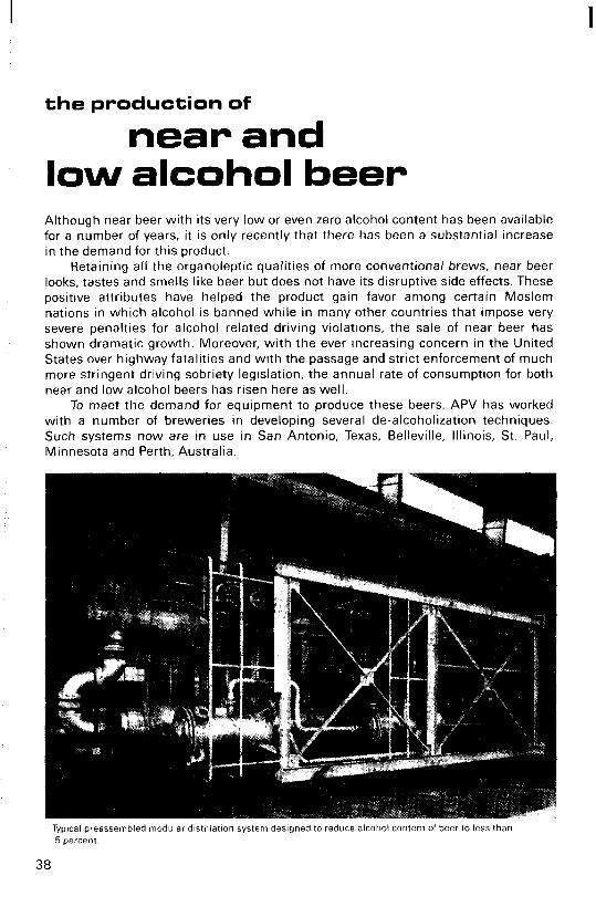
To meet the demand for equipment to produce these beers, APV has worked with a number of breweries in developing several de-alcoholization techniques. Such systems now are in use in San Antonio, Texas, Belleville, Illinois, St. Paul, Minnesota and Perth, Australia.
Typical preassembled modular distillation system designed to reduce alcohol content of beer to less than 5 percent
38

. COOLIN6
CONOENSER
S l A l P P l N G
O E ESTERIZEA AECOMBINEA
REBOILER
- STEAM
P A E H E A l HOT WUlEA HOT WATER
P R 0 0 u E 1 I
F E E O B A L A N C t TANK
L- TO WELL HOT
STEAM -
39
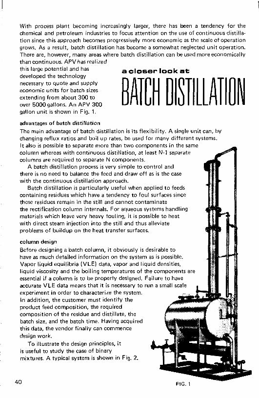
With process plant becoming increasingly larger, there has been a tendency for the chemical and petroleum industries to focus attention on the use of continuous distilla- tion since this approach becomes progressively more economic as the scale of operation grows. As a result, batch distillation has become a somewhat neglected unit operation. There are, however, many areas where batch distillation can be used more economically than continuous. APV has realized
BATCH DlST LLAT this large potential and has developed the technology necessary to quote and supply economic units for batch sizes extending from about 300 to over 5000 gallons. An APV 300 ON
a closer look at
gallon unit i s shown in Fig. 1.
advantages of batch distillation The main advantage of batch distillation is i t s flexibility. A single unit can, by changing reflux ratios and boil up rates, be used for many different systems. I t also is possible to separate more than two components in the same column whereas with continuous distillation, a t least N-1 separate columns are required to separate N components.
A batch distillation process i s very simple to control and there i s no need to balance the feed and draw off as i s the case with the continuous distillation approach.
Batch distillation is particularly useful when applied t o feeds containing residues which have a tendency to foul surfaces since these residues remain in the s t i l l and cannot contaminate the rectification column internals. For aqueous systems handling materials which leave very heavy fouling, it i s possible t o heat with direct steam injection into the s t i l l and thus alleviate problems of buildup on the heat transfer surfaces.
column design Before designing a batch column, it obviously i s desirable to have as much detailed information on the system as i s possible. Vapor liquid equilibria (VLE) data, vapor and liquid densities, liquid viscosity and the boiling temperatures of the components are essential if a column i s to be properly designed. Failure t o have accurate VLE data means that it i s necessary to run a small scale I experiment in order to characterize the system. In addition, the customer must identify the product feed composition, the required composition of the residue and distjllate, the batch size, and the batch time. Having acquired this data, the vendor finally can commence design work.
To illustrate the design principles, it is useful to study the case of binary mixtures. A typical system is shown in Fig. 2.
40 - FIG. 1

FIG, 2 MOLE FRACTION ' A IN LIQUID
Once the VLE data have been established, it becomes a straightforward task to calcu- late the number of theoretical stages and reflux ratios.
There are two main techniques for operating a batch column. One is to work with constant reflux ratio during the complete run. The effect of this method is charted in Fig. 3. As the composition of the more volatile component (MVC) in the s t i l l xw de- creases, so the fraction of MVC in the top product decreases. To obtain a se t composi- tion of say 90% i n the total amount of top product collected, it wil l always be neces- sary to collect initially a t a higher composition of about 95% to compensate for a composition below specification a t the end of the run. The advantage of constant reflux is that control and operation are very simple.
The second method is to increase the reflux ratio during the run in order to main- tain a steady top product composition. This i s shown in Fig. 4 where the increase in the slope of the operating line i s obtained by increasing the reflux ratio. The gradient
41
of the operating line ($) is obtained from the enrichment equation given below.
This equation assumes constant molal overflow
Y, x,+~ is the mole fraction of the MVC in the liquid arriving a t the nth stage
xd D V L
is the mole fraction of the MVC in the vapor leaving the nth stage
i s the mole fraction of the MVC in the top product is the molal f low rate of top product is the molal vapor flow rate in the column is the molal liquid flow rate in the column
The reflux ratio R is given by
LIV 1 - (L IV)
R =
With the VLE data and the top and bottom compositions, it then is possible to calculate graphically by the McCabe & Thiele procedure the minimum reflux ratio, minimum number of theoretical stages, and other such parameters. In batch distilla- tion in particular, these procedures are tedious and time consuming since, of course, the composition of the liquid in the s t i l l changes with time and it i s necessary to repeat the calculations many times. Obviously, the procedures become even more time con- suming with multi-component systems.
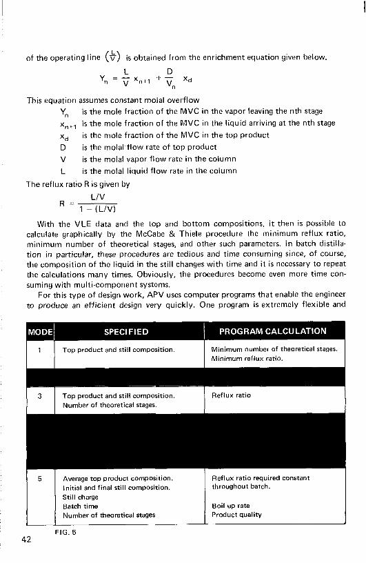
For this type of design work, APV uses computer programs that enable the engineer to produce an efficient design very quickly. One program is extremely flexible and
I 1 I Top product and still composition.
product and still composition. Number of theoretical stages.
Average top product composition. Initial and final still composition. Still charge Batch time Number of theoretical stages
FIG. 5 42
Minimum number of theoretical stages. Minimum reflux ratio.
Reflux ratio I
Reflux ratio required constant throughout batch.
Boil up rate Product quality
operates in a different series of modes as is charted in the Fig. 5 table. Naturally, the VLE data have to be specified for all modes. The program further assists in the determination of the number of theoretical stages. Other modes also are available to provide different permutations of operation.
To help determine the sizing of the column diameter, APV uses various programs which incorporate different proprietary methods including those of Fractionation Research Inc. (FRI) of California.
column internals
The choice of internals for the column depends mainly on the product being processed and the size of the column to be used. To meet virtually every parameter, packed columns as well as sieve, bubble, and ballast trays are available. As a general rule, sieve trays are not used frequently in batch columns since the turn down ratio of most trays of this type is only about 1.5 to 1. This reduces one of the main advantages of batch columns, mainly flexibility. Usually, small batch columns are packed since the efficiency of trays of less than 2’ diameter often decreases rapidly. Ballast trays, although expensive, are often used for larger columns since they are efficient and have turn down ratios of up to 9 to 1.
control
The control of batch columns is very simple and therefore, required instrumentation usually is quite inexpensive. Constant reflux operation can be handled by a ratio controller or by using a timed deflection of condensate. For operation with variable reflux, the control of the reflux ratio must be tied to some property of the top product that undergoes a sufficiently large change in value for change in composition. Manual control of this type of reflux operation is not feasible.
Numerous batch distillation systems have been supplied to customers who require the separation of many different components. To simplify the operation of these systems, APV CREPACO has developed a range of proprietary computers specifically designed for process control. Use of an ACCOS microprocessor enables the operator to switch from one type of separation to another without having to make many manual adjustments on the control panel. In addition, the computer can be programmed to automatically take care of all necessary tails cuts as well as to clean the system during interims between the various separations. In one batch distillation system supplied to a processor in Puerto Rico, an APV ACCOS 2s computer is used to control distillation while an IBM XT handles the logging of all data.
batch systems/continuous distillation
In a number of duties, it is essential that the base product contain only very small amounts of one component. For example, in the recovery of solvents from water, it is mandated that the water may retain only trace quantities of solvents before being pumped to waste. Since one disadvantage of a batch system is that there is no stripping section, it is necessary to boil the batch pot for relatively long periods of time in order to reduce the residual solvent to trace quantities.
To resolve this problem, a number of batch distillation systems with the capability of being operated in the continuous mode have been supplied. By incorporating one, two or three feed points on the column, the feed can be pumped directly to the column instead of to the batch tank. Furthermore, a separate small holdup/reboiler is furnished in certain cases so that the batch tank and its associated reboiler need not be utilized for the continuous operation.
43
APV Crepaco Inc Executive and International Headquarters 9525 West Bryn Mawr Ave., Rosemont, IL 60018
Engineering and Manufacturing 395 Fillmore Ave., Tonawanda, NY 14150
(708) 678-4300 FAX: (708) 678-4407
(716) 692-3000 FAX: (716) 692-1715
Sales Offices: Charlotte, NC/(704) 376-0209 Chicago (Rosemont), IL/(708) 678-4300 Columbus, OH/(614) 846-6415 Dallas (Irving), Texas/(214) 257-3455 Los Angeles (Cerritos), CA/(213) 926-9700 Minneapolis, MN/(612) 544-8731 Mt. Laurel, NJ/(609) 235-6800 - Nashville, TN/(615) 255-0342 Metropolitan New York (Montvale, NJ)/(201) 930-0001 Salt Lake City, UT/(801) 262-8494 Seattle, WA/(206) 575-8900 APV Canada, Inc. - Toronto/(416) 850-1852
591