[email protected] Installation and Operation Manual ENGLISH Manual... · 2016. 11. 29. · LP4...
43
M.D. Micro Detectors Strada S. Caterina, 235 41122 Modena Italy Tel. +39 059 420411 Fax +39 059 253973 www.microdetectors.com [email protected]m LP4 SERIES SAFETY LIGHT CURTAIN TYPE 4 AVAILABLE ALSO WITH MUTING FUNCTION LANGUAGE Installation and Operation Manual ENGLISH M.D. Micro Detectors CAT8ELP1251902 1/43
Transcript of [email protected] Installation and Operation Manual ENGLISH Manual... · 2016. 11. 29. · LP4...

M.D. Micro Detectors Strada S. Caterina, 235
41122 Modena Italy Tel. +39 059 420411 Fax +39 059 253973
www.microdetectors.com [email protected]
LP4 SERIES SAFETY LIGHT CURTAIN TYPE 4
AVAILABLE ALSO WITH MUTING FUNCTION LANGUAGE
Installation and Operation Manual ENGLISH
M.D. Micro Detectors CAT8ELP1251902 1/43

M.D. Micro Detectors Strada S. Caterina, 235
41122 Modena Italy Tel. +39 059 420411 Fax +39 059 253973
www.microdetectors.com [email protected]
LP4 SERIES SAFETY LIGHT CURTAIN TYPE 4
AVAILABLE ALSO WITH MUTING FUNCTION LANGUAGE
Installation and Operation Manual ENGLISH
M.D. Micro Detectors CAT8ELP1251902 2/43
CONTENTS
1.0 ABOUT THIS DOCUMENT ............................................................................................................. 3 1.1 Function of this document ................................................................................................................ 3
1.2 Symbols used in this document ......................................................................................................... 3
2.0 WITH REFERENCE TO SAFETY ....................................................................................................... 4 2.1 Skilled personnel ............................................................................................................................... 4
2.2 Fields of use of the device ................................................................................................................. 4
2.3 General safety instructions and measures of protection .................................................................. 5
2.4 Disposal.............................................................................................................................................. 5
3.0 DESCRIPTION OF THE PRODUCT ................................................................................................... 5 3.1 Brief description ................................................................................................................................ 5
3.1.1 Special models and accessories. .................................................................................................... 6
3.2 Coding system.................................................................................................................................... 6
3.3 Available models ................................................................................................................................ 7
4.0 INSTRUCTIONS FOR POSITIONING THE SAFETY LIGHT CURTAINS .................................................. 9 4.1 Respecting the safety distance .......................................................................................................... 9
4.2 How to calculate the safety distance S in conformity with EN ISO 13855 and EN ISO 13857 ........ 10
5.0 MINIMUM DISTANCE FROM REFLECTING SURFACES .................................................................. 13 5.1 How to calculate the minimum distance from reflective surfaces ................................................. 13
6.0 COMMISSIONING ...................................................................................................................... 14 6.1 Mechanical mounting ...................................................................................................................... 14
6.2 Safety light curtain Alignment ......................................................................................................... 14
6.3 Applying Muting sensors. ................................................................................................................ 15
6.4 Electrical installation. ...................................................................................................................... 15
6.5 Colours and symbols used to indicate the cables and LEDs of the display. .................................... 15
7.0 TECHNICAL SPECIFICATIONS. ..................................................................................................... 21 8.0 PANEL AND DIAGNOSTICS INDICATIONS .................................................................................... 22 9.0 LISTS OF AVAILABLE MODELS AND MAIN CHARACTERISTICS ....................................................... 25 10.0 MECHANICAL DIMENSIONS OF THE LIGHT CURTAINS AND STANDARD ACCESSORIES .................. 35 11.0 CONTENT OF THE PACKAGE ....................................................................................................... 40 12.0 LIST OF APPLICABLE ACCESSORIES ............................................................................................. 41 13.0 CHECKING THE SYSTEM ............................................................................................................. 42
13.1 Purpose of the checks...................................................................................................................... 42
13.2 Checks prior to commissioning ........................................................................................................ 42
13.3 Regularity of the checks by qualified personnel ............................................................................. 42
13.4 Regular checks on the effectiveness of the protection device........................................................ 42
14.0 CE DECLARATION OF CONFORMITY............................................................................................ 42 15.0 GUARANTEE .............................................................................................................................. 43

M.D. Micro Detectors Strada S. Caterina, 235
41122 Modena Italy Tel. +39 059 420411 Fax +39 059 253973
www.microdetectors.com [email protected]
LP4 SERIES SAFETY LIGHT CURTAIN TYPE 4
AVAILABLE ALSO WITH MUTING FUNCTION LANGUAGE
Installation and Operation Manual ENGLISH
M.D. Micro Detectors CAT8ELP1251902 3/43
1.0 ABOUT THIS DOCUMENT
Please read this document carefully before mounting, starting, using and servicing LP4 multi-beam safety light curtain; it contains detailed instructions that must be followed with care. In addition, pay special attention to Chapter 2 “With reference to safety”.
THIS DOCUMENT IS NOT IN ITS ORIGINAL LANGUAGE
1.1 Function of this document
This document provides the technical personnel of the manufacturer of a machine or the manager of the machine with the necessary instructions for safe mounting, electrical connection, starting and normal operation and maintenance of LP4 safety light curtain. The design and use of safety devices that utilize LP4 multi-beam safety light curtains require specific knowledge, but this is not entirely provided in this document. The prescriptions of authorities and of the law must also be fundamentally respected for the installation and during normal operation of LP4 safety light curtain.
1.2 Symbols used in this document
Warning to avoid danger! A warning indicates real or potential hazards. Its task is to indicate procedures and behaviour that can avoid accidents. Read and follow these instructions carefully.
Indication Indications that can help achieve better performance.
Emitter or Passive reflector element symbol This symbol identifies devices that have the function of a projector.
Receiver or Active element symbol This symbol identifies devices that have the function of a receiver.
Body detection This symbol marks devices designed to identify a person entering a protected area. It refers to multi-beam light curtains with 2, 3 or 4 beams. These light curtains are usually cost-effective and feature a long range, they enable creating protection for extensive areas and on more than one side, using diverter mirrors. These models are available in the LP4 series.
Limb or presence detection This symbol marks devices designed to identify limbs entering a protected area or to identify the presence of a person in a protected area. For presence detection, with light curtains in a horizontal position, resolutions of between 50 and 116mm are to be used, the height off the ground is calculated in relation to these values. For this function the LP4 series features models with resolutions of 50 and 90mm.
Hand detection This symbol marks devices designed to identify a hand entering a protected area. It refers to light curtains with a resolution less than or equal to 40mm; these resolutions allow safety distances compatible with short loading and unloading times and a low level of operator fatigue. For this function the LP4 series features models with resolutions of 30 and 40mm.
Muting Function This symbol marks devices that have the Muting and Override function.

M.D. Micro Detectors Strada S. Caterina, 235
41122 Modena Italy Tel. +39 059 420411 Fax +39 059 253973
www.microdetectors.com [email protected]
LP4 SERIES SAFETY LIGHT CURTAIN TYPE 4
AVAILABLE ALSO WITH MUTING FUNCTION LANGUAGE
Installation and Operation Manual ENGLISH
M.D. Micro Detectors CAT8ELP1251902 4/43
2.0 WITH REFERENCE TO SAFETY
Warning! The level of protection of the safety light curtain must be compatible with the dangerousness of the system to control, devices downstream from the safety light curtain must be compatible with the safety light curtain itself and with the required safety level. - The machine must be able to be controlled electrically. - It must be possible to stop the dangerous parts of the machine with an electric control achievable in a definite time and if necessary verified directly.
\
Warning! The features of the safety light curtain must be chosen according to the size of the access area to the dangerous zone, the part of the human body subjected to the danger, the distance of the point of access from the dangerous point, the response time of the safety light curtain, the response time of the downstream devices and the time for stopping the dangerous movement.
Warning! All the remaining hazardous conditions of the machine must be verified and suitable equipment must be used to neutralize them. It must not be possible to reach the dangerous zone without going through the protection surface controlled by the safety light curtain. It must not be possible to stop between the protection surface controlled by the safety light curtain and the dangerous zone.
Warning! Check that the environmental conditions are compatible with the features of the safety light curtain. Check the effect of reflective surfaces to the side of the path of the light beams, in general respect the indicated safety distances. Consider the effect of putting transparent panels or the like in between that can change the beam angle of the safety light curtain. Prevent the safety light curtain's optical window from getting damaged or altered with scratches and opacification. Do not expose the receiver to strong natural or artificial sources of light, including flashing stroboscopic sources. Avoid exposing the receiver directly to the projection of optical beams of other optical devices. Check that the ambient temperature does not exceed the stated limits. Consider the effect of smoke, vapours, liquids and powders that can alter the transparency of the air or foul the optical window.
Warning! Periodically perform the procedures for checking the functionality of the safety light curtain.
2.1 Skilled personnel
Only qualified personnel are authorized to mount, start up, use and service the LP4 multi-beam safety safety light curtain. A qualified person is one who: - has adequate technical training - has been educated by the person in charge of Machine Safety on its use and the current safety directives - accesses the operating instructions.
2.2 Fields of use of the device
The LP4 safety light curtains are Type-4 electro-sensitive protection equipment (ESPE) in accordance with IEC 61496-1 and IEC 61496-2. They can be employed in safety applications up to Category 4 in conformity with EN ISO 13849, up to SIL CL 3 in conformity with EN 62061 or up to PL e in conformity with EN 13849. They meet the requirements of the Machinery Directive 2006/42/EC and are used to: - protect the area of access to dangerous point. - detect human presence in dangerous zones. - protect the accesses to dangerous zones. - ensure the safety of automated of palletizing and de-palletizing systems. - ensure conditional access control in safety for passageways of machines, warehouses, loading/unloading bays. - select alternative control of different danger zones in safety.
Use to standard LP4 safety light curtains must be used only in accordance with Chapter 2.2 “Fields of use of the device”. If the device is used for other purposes or if it is modified, even in the phase of mounting or installation, this invalidates all warranty rights with M. D. Micro Detectors.

M.D. Micro Detectors Strada S. Caterina, 235
41122 Modena Italy Tel. +39 059 420411 Fax +39 059 253973
www.microdetectors.com [email protected]
LP4 SERIES SAFETY LIGHT CURTAIN TYPE 4
AVAILABLE ALSO WITH MUTING FUNCTION LANGUAGE
Installation and Operation Manual ENGLISH
M.D. Micro Detectors CAT8ELP1251902 5/43
2.3 General safety instructions and measures of protection
Safety instructions! To ensure LP4 safety light curtains are used to standard and in a safe manner it is necessary to observe the following points:
• For the installation and use of the LP4 safety light curtain as for commissioning it and the repeated technical tests, national and international regulations apply, particularly: – Machinery directive 2006/42/EC – the Directive on work equipment operators 2009/104/EC – the accident prevention prescriptions and safety rules – other important safety prescriptions. • The manufacturers and operators of the machine on which the LP4 safety light curtain is used must, in agreement with the relevant authority and under their own responsibility, apply all the current safety rules and prescriptions and are also in charge of their observance. • It is absolutely necessary to observe the guidelines on checking these operating instructions (see chapter 6 “Commissioning”). • The checks must be carried out by qualified persons, that is by authorized and specially appointed persons, and they must be documented so as to be comprehensible at any moment. • The operating instructions contained in this manual must be set at the disposal of the operator of the machine used with LP4 safety light curtain. The machine operator must be educated by qualified personnel and urged to read the operating instructions.
2.4 Disposal
Dispose of unusable or unrepairable devices always in observance of current national prescriptions on the subject of waste disposal.
3.0 DESCRIPTION OF THE PRODUCT
3.1 Brief description
The LP4 series safety light curtains are multi-beam optico-electronic safety devices, built in compliance with the IEC 61496-1 and 2 standards, are Type 4, integrity level SIL 3, SILCL 3, performance level PL and Category 4 and therefore applicable for the protection of the operators of systems or machines under conditions of frequent interaction with a dangerous area.
LP4 safety light curtains have a rectangular profile of 50x60mm, the distance of 50mm refers to the front side, each of the remaining three sides has a groove for fastening; they are extremely reliable devices, they provide two protected static safety PNP outputs, so they are not subject to output contact wear or affected by strong vibration, they are able to detect internal faults, control external contacts (EDM) and, also in the event of a fault, ensure safe behaviour in any case.
With a free area the level of the two outputs is enabled to be high (status ON, outgoing current), with an occupied area or in case of fault the level is low (status OFF).
The Manual or Automatic start/restart mode and external contact control (EDM) can be selected with changes to the receiver wiring. Two ranges are normally available that can be selected on the emitter that can also be selected with changes to the wiring; a Test input is also available on many models.
There are models composed of pairs of Emitters and Receivers with optics in a row having resolutions (minimum measurable diameter) of 30, 40, 90mm, heights from 300 to 1800mm and ranges from 6 to 80m, dedicated to secure detection of hand and limbs. In addition there are also multi-beam optics with 2, 3, 4 beams dedicated to access control, for these models there are also pairs composed of an Active element that integrates emitters/receivers and a Passive reflector element with a maximum range of 6m, these models are indispensable if it is not possible to take the power supply to the remote element.
The models with the Muting function enable maintaining the active state of the outputs and therefore not cause the movement to stop, also in case of breaks in the beams, if this movement has been evaluated as finished or in a phase that is no longer dangerous for the operator, or since the break was not caused by an operator but by material enabled to access the danger zone.
The models with Muting have from two to four inputs dedicated to standard sensors which supply information that, suitably processed, cause the safety function to be suspended; the guarantee that this happens safely is given by the redundancy of the signals, their dynamism and the safety procedure with which they are processed. Different types of Muting can be chosen via the wiring: with two or four sensors, two-way or mono, with safety logics based on the sequentiality or simultaneity of the signals.
These safety light curtain models also have an Override function that, after a manual command in safety, enables clearing the access if, because of incorrect recognition, the material remains blocked; they also provide an output for piloting and checking the light that indicates that the Muting function is in progress.
The emitters have an M12 5 pole connector. The receivers have different configurations depending on the complexity of the functions, models with an M23 19 pole connector and with one or two M12 5 pole front connectors for 2 or 4 Muting sensors, or a single M23 19 pole connector that has 2 inputs for Muting sensors, or a single M23 19 pole or M12 8 pole connector on models without Muting. For the power supply and output cables and the Muting sensors cables no shielding is required, lengths of up to 100m are permissible. The required power supply voltage is 24VDC ±20%, its current absorption is moderate (maximum 9W per pair), the peak output current is 500mA, suited to drive the power contactors directly too.

M.D. Micro Detectors Strada S. Caterina, 235
41122 Modena Italy Tel. +39 059 420411 Fax +39 059 253973
www.microdetectors.com [email protected]
LP4 SERIES SAFETY LIGHT CURTAIN TYPE 4
AVAILABLE ALSO WITH MUTING FUNCTION LANGUAGE
Installation and Operation Manual ENGLISH
M.D. Micro Detectors CAT8ELP1251902 6/43
The degree of protection of the container is IP65, suitable also for dusty environments and tolerant of sprays, except for the front surface that has strict optical requirements.
The completeness of the available functions enables creating versatile and integrated protection systems.
3.1.1 Special models and accessories.
Arms are available composed of standard technical profiles of cross-section 30x30mm that, applied to safety light curtains with Muting, can support ready-wired Muting sensors and be a cost-effective solution integrated in standard applications for palletizing / de-palletizing.
3.2 Coding system
Tab.:1 gives the meaning of the codes of the available models. The models are supplied in kit form composed of a pair (emitter/receiver), the single elements are available only to make up for a return. For an overview of the main features of the models ready for delivery or available on request, see Tab.:2 and 3 in this chapter. For a complete and detailed list of the actually coded models and their related features, see Chapter 9. Directly contact M. D. Micro Detectors for any explanation.
LP4 SERIES CONSTRUCTION OF MODEL CODES
POSITION CODE DESCRIPTION
1 LP4 Type-4 safety light curtains in housing of cross-section 50x60mm
2
R Receiver
E Emitter
F Active element, emitter + receiver with M12, 8 pole connector
T Active element, emitter + receiver with M23, 19 pole connector
P Passive element, reflector for active multiple beam elements
ER, PF, PT Pair, emitter + receiver, reflector + active M12, reflector + active M23
3 / Separator
4 30, 40, 90 Light curtain, resolution in mm; 30, 40 hand protection; 90 limb protection
0A, 0B, 0C Multiple beams light grid, number of beams 2, 3, 4; body protection. Corresponding centre distance of the beams 500, 400, 300mm.
5 - Separator
6 030 to 160
Nominal height of controlled area in cm for light curtain models: 030, 045, 060, 075, 090, 105, 120, 135, 150, 165, 180.
050, 080, 090 Centre distance of the end beams in cm for light grid models.
7
Emitter or Passive or Receiver element without Muting function.
M2 Elements with Muting function and inputs for two sensors
M4 Elements with Muting function and inputs for four sensors
8 L Long range
S Super extended range
Tab.:1; Chap.:3

M.D. Micro Detectors Strada S. Caterina, 235
41122 Modena Italy Tel. +39 059 420411 Fax +39 059 253973
www.microdetectors.com [email protected]
LP4 SERIES SAFETY LIGHT CURTAIN TYPE 4
AVAILABLE ALSO WITH MUTING FUNCTION LANGUAGE
Installation and Operation Manual ENGLISH
M.D. Micro Detectors CAT8ELP1251902 7/43
3.3 Available models
Tab: 2 and 3 give an overview of the series actually available, are ordered from the smallest resolution to the highest one and light curtain to multi-beam greed, by Emitter/Receiver pair to Passive/Active elements, by Muting function.
Tab.:3 gives the preferential applications.
See also the tables of Chap.:9 for a complete list of the available models and corresponding specifications.
SERIES
LP4 OVERVIEW OF THE FUNCTIONAL CHARACTERISTICS OF THE AVAILABLE MODELS
APPLICATION
RE
SO
LU
TIO
N
HE
IGH
T
OF O
PT
ICS
ST
AN
DA
RD
R
AN
GE
S
(SELECTABLE
)
EX
TE
ND
ED
R
AN
GE
S
(SELECTABLE
)
SU
PER
EX
TEN
DED
R
AN
GES
(S
ELE
CTABLE
)
ELE
ME
NT
S
IN P
AIR
S
MUTING
MU
TIN
G
SE
NS
OR
S
PAIRED MODELS
*: numbers #: letters
SE
E N
OT
ES
i
n T
ab
.:3
(mm) (mm) (m) (m) (m) Type No. Ref.
HAND PROTECTION
Curtain of
beams
30 300 to
1200
0 to 6 or
1 to 16 - -
Emitter Receiver
Mono and
Two-way External 2 or 4 LP4ER/30-***M4 1
40 600 900 1200
- 8 to 30
or 18 to 60
- Emitter Receiver
- - - LP4ER/40-***L 2
40 300 to
1800
0 to 6 or
1 to 16 - -
Emitter Receiver
Mono and
Two-way External 2 or 4 LP4ER/40-***M4 3
40 600 900 1200
- 8 to 30
or 18 to 60
- Emitter Receiver
Mono and
Two-way External 2 or 4 LP4ER/40-***M4L 4
LIMB PROTECTION
Curtain of
beams
90 300 to
1800
0 to 6 or
1 to 16 - -
Emitter Receiver
Mono and
Two-way External 2 or 4 LP4ER/90-***M4 5
ACCESS PROTECTION
Multiple beams
Beams Pitch 0 to 6 or
1 to 16
8 to 30 or
18 to 60
18 to 40 or
25 to 80
- - - LP4ER/0#-0** LP4ER/0#-0**L LP4ER/0#-0**S
6 2,3,4
500 400 300
Emitter Receiver
2,3,4 500 400 300
0 to 6 or
1 to 16
8 to 30 or
18 to 60 -
Emitter Receiver
Mono and
Two-way External 2 or 4
LP4ER/0#-0**M4 LP4ER/0#-0**M4L
7
2,3,4 500 400 300
0 to 6 - - Emitt./Rec.
Passive Reflector
- - - LP4PF/0#-0** 8
2,3,4 500 400 300
0 to 6 - - Emitt./Rec.
Passive Reflector
Mono and Two-way
External 2 or 4 LP4PT/0#-0**M4 9
2,3,4 500 400 300
0 to 6 - - Emitt./Rec.
Passive Reflector
Mono External 2 LP4PT/0#-0**M2 10
Tab.:2; Chap.:3

M.D. Micro Detectors Strada S. Caterina, 235
41122 Modena Italy Tel. +39 059 420411 Fax +39 059 253973
www.microdetectors.com [email protected]
LP4 SERIES SAFETY LIGHT CURTAIN TYPE 4
AVAILABLE ALSO WITH MUTING FUNCTION LANGUAGE
Installation and Operation Manual ENGLISH
M.D. Micro Detectors CAT8ELP1251902 8/43
LP4 SERIES TYPICAL APPLICATIONS OF THE AVAILABLE MODELS
Re
leva
nt
no
tes
to T
ab
.:2
PR
OT
EC
TIO
N
INT
EG
RA
TE
D
MU
TIN
G
DESCRIPTION OF THE TYPICAL APPLICATION
Da
ta o
f m
od
els
S
ee
Ch
ap
.:9
T
ab
.: n
um
be
r
1
Hand protection Ø30mm and Muting by external sensors over an area of 0.3 to 1.2m x 0 to 16m and need to keep the safety distance greatly reduced. Need to exclude safety at specific intervals of manual work by Muting via limit stop sensors. Protection of windows for entering/leaving machines for making small items and with greatly reduced safety distances. The range of 16m enables controlling more than one side using deflector mirrors (range with one mirror 13m, two mirrors 11m).
1
2
Hand protection Ø40mm over an area of 0.6 to 1.2m x 8 to 60m and need to keep the safety distance reduced. Possibility of connecting to safety modules or PLC to perform complex Muting logic. The range of 60m enables controlling more than one side using deflector mirrors (range with one mirror 50m, two mirrors 43m) or better tolerate dusty environments. Can be used as a presence sensor that can be mounted near the ground. Pay attention to the deterioration of the beam angle in applications in dusty environments and with reflective surfaces.
2
3
Hand protection Ø40mm and Muting by external sensors over an area of 0.3 to 1.8m x 0 to 16m need to keep the safety distance reduced. Need to exclude safety at specific intervals of manual work by Muting via limit stop sensors. The range of 16m enables controlling more than one side using deflector mirrors (range with one mirror 12m, two mirrors 9m).
3
4
Hand protection Ø40mm and Muting by external sensors over an area of 0.3 to 1.8m x 8 to 60m need to keep the safety distance reduced. Need to exclude safety at specific intervals of manual work by Muting via limit stop sensors. The range of 60m enables controlling more than one side using deflector mirrors (range with one mirror 50m, two mirrors 43m). Pay attention to the deterioration of the beam angle in applications in dusty environments and with reflective surfaces.
4
5
Limb protection Ø90mm and Muting by external sensors over an area of 0.3 to 1.8m x 0 to 16, presence check in danger area (in view or not in view from control position) with horizontal positioning at minimum height 600mm. Need to exclude safety at specific intervals of manual work by Muting via limit stop sensors.
5
6
Access protection, 2, 3, 4, beams, models with ranges of 0 to 16, 8 to 60, 18 to 80m, to detect a body entering a danger area (robotized areas, automatic machining centres). The range of 60m or 80m enables easily controlling perimeters with more than one side using deflector mirrors (maximum range with one mirror 68m, two mirrors 57m) or better tolerate dusty environments. Pay attention to the deterioration of the beam angle in applications in dusty environments and with reflective surfaces. The receiver models with a range of 60 and 80m use an M12 8 pole connector.
6
7
Access protection, 2, 3, 4, beams and Muting by external sensors, models with ranges of 0 to 16 or 8 to 60m. Can be used to protect large infeeds/outfeeds of material from machining centres and loading/unloading bays; applications with a long range are not in theory compatible with traditional Muting in which the overall dimensions of the load help maintain protection, but require more complex systems.
7
8
Access protection 2, 3, 4 beams, composed of an Active unit consisting of a multi-beam Emitter/Receiver and a passive reflector element (not wired),working distance up to 0 to 6m. The active element has an M12, 8 pole connector. To be used to detect a body entering a danger area (robotized areas, automatic machining centres) in which it is not possible to take the power supply to the second element.
8
9
Access protection for palletizers with 2, 3, 4 beams, with passive reflector and Muting by 2, 4 external sensors, for ranges of up to 6m without needing to wire the second element, in this case the main wired element is a multi-beam projector/receiver. It is advised to use 2 to 4 Muting sensors of the reflex type (with catadioptric reflector) in sympathy with the passive element. Optimal solution for standard applications, relatively long ranges and reduction in installation labour costs.
9
10
Access protection for palletizers with 2, 3, 4 beams, with passive reflector and Muting by 2 external sensors, for ranges of up to 6m without needing to wire the second element, in this case the main wired element is a multi-beam projector/receiver. It is advised to use 2 Muting sensors of the reflex type (with catadioptric reflector) in sympathy with the passive element. The sensor inputs are accessible via the M23 connector, no other connectors are present. Optimal solution for standard applications, relatively long ranges and reduction in installation labour costs.
10
Tab.:3; Chap.:3

M.D. Micro Detectors Strada S. Caterina, 235
41122 Modena Italy Tel. +39 059 420411 Fax +39 059 253973
www.microdetectors.com [email protected]
LP4 SERIES SAFETY LIGHT CURTAIN TYPE 4
AVAILABLE ALSO WITH MUTING FUNCTION LANGUAGE
Installation and Operation Manual ENGLISH
M.D. Micro Detectors CAT8ELP1251902 9/43
4.0 INSTRUCTIONS FOR POSITIONING THE SAFETY LIGHT CURTAINS
4.1 Respecting the safety distance
A safety distance must be maintained between the protection surface composed of the beams of the safety light curtain and the point of danger. This distance must ensure that, considering a maximum approach speed defined by the standard, the point of danger can only be reached when sufficient time has elapsed so that the dangerous state of the machine has ended. The safety distance in accordance with EN ISO 13855 depends: - in direct proportion on the total time for stopping the machine or system, which corresponds to the sum of the individual times of reaction of the whole safety chain (the individual response times are indicated in the technical documentation of the safety devices and of the machine itself or must be verified with specific measures). - in direct proportion on the approach speed. - in direct proportion on the resolution of the safety light curtain, or inversely to the number of beams for the unit of height. If the machine is subject to a specific standard of type C, the indications of this standard must be followed.
Danger of failed recognition!
Particularly in access protection applications, people may stop in the danger area, but not in the optical beam between the projector and the receiver, and their presence might not be recognized. Make sure that dangerous states can only occur when there are no persons in the danger area. Make sure that the system restart control is effected from a point providing full visibility of the danger area and that this control cannot be reached from within said area.
No protection function is secure if the safety distance is not correct!
It is indispensable to mount the safety light curtains at the correct safety distance to ensure the function of protection.
If there is a C-type standard for the application you are creating, follow its instructions!
The following instructions apply only to an industrial environment, that is to say where only adults of normal constitution are expected to be present.
The Muting sensors must correctly distinguish between access of material and access by persons!
The sensors must detect the material and not the pallet on which the material stands, otherwise the distinction between material and people is not effective. The sensors must not be activated simultaneously by unintentional behaviour of the personnel. It is essential for the information on the state of the Muting sensors to reach the inputs via two completely separate channels (from two or more sensors connected to the safety light curtain with different cables); it is not permissible to process the signals with a single device that is not for safety before applying them to the safety light curtain input.

M.D. Micro Detectors Strada S. Caterina, 235
41122 Modena Italy Tel. +39 059 420411 Fax +39 059 253973
www.microdetectors.com [email protected]
LP4 SERIES SAFETY LIGHT CURTAIN TYPE 4
AVAILABLE ALSO WITH MUTING FUNCTION LANGUAGE
Installation and Operation Manual ENGLISH
M.D. Micro Detectors CAT8ELP1251902 10/43
4.2 How to calculate the safety distance S in conformity with EN ISO 13855 and EN ISO 13857
Here we give the general procedures for calculating the minimum safety distance S, these instructions must be followed if there is not a specific standard of type C for the machine to make safe. Depending on the application it is necessary to use different calculation schemes. In general the formula has this form: S = K * T + C Where… S = [mm] Safety distance K = [mm/s] Approach speed, a speed of 2000mm/s is indicated for the upper limbs and 1600 for the lower limbs. T = [s] Total stopping time: response time of the entire safety device + machine stopping time. C = [mm] Safety distance supplement, to ensure that the dangerous zone cannot be reached by climbing over the beams or inserting limbs between the beams. It is provided by the standard, it takes on a fixed value or is calculated according to the optical features of the safety light curtain and its utilization in the application.
The reaction time of the safety light curtain alone is stated on the product label of the receivers and in this document in the tables of Chap.:9.
The standard considers different methods of approach:
1) PERPENDICULAR APPROACH
Safety light curtain in vertical position. Angle between safety light curtain and surface of 90° ±5°
2) PERPENDICULAR APPROACH
Safety light grid in vertical position. Angle between safety light curtain and surface of 90° ±5°
3) HORIZONTAL APPROACH
Safety light curtain in horizontal position. Angle between safety light curtain and surface of 0° ±5°
4) OBLIQUE APPROACH
Safety light curtain in angled position. Two cases are considered for different angle values
With ≥30° we have the perpendicular approach
With <30° we have the horizontal approach
Tab.:1; Chap.:4

M.D. Micro Detectors Strada S. Caterina, 235
41122 Modena Italy Tel. +39 059 420411 Fax +39 059 253973
www.microdetectors.com [email protected]
LP4 SERIES SAFETY LIGHT CURTAIN TYPE 4
AVAILABLE ALSO WITH MUTING FUNCTION LANGUAGE
Installation and Operation Manual ENGLISH
M.D. Micro Detectors CAT8ELP1251902 11/43
● Calculate S with the following procedure for applications of protection with optical safety light curtains over which it is possible to climb.
If an optical safety light curtain is installed without any supplementary mechanical protection on the top, and therefore it is possible to enter the protected area from above, it is necessary to define the safety distance considering two methods: - Access from above. - Access through the beams. - Access from below, not considered now, can be excluded if the lowest beam has a maximum height of 200mm from the surface, or by installing mechanical protection. The safety distance, considering access from above, must be such as not to allow reaching the danger area; this safety distance is obtained from Tab,:2 of ISO 13855, here Tab.:3; Chap.:4 The safety distance, considering access between the beams, is obtained from the procedures indicated below that envisage access only through the beams. The safety distance to choose will be the greater one of the two. To have indications of the dimensions of any mechanical protection to superimpose on the safety light curtain or only mechanical protection not closed on the top part, please refer to standard EN ISO 13857.
1) Reference surface
2) Dangerous point or danger area
3) Safety light curtain
a) Height above the surface of the dangerous point or of the higher point of the danger area
b) Height above the surface of the top of the optical window of the safety light curtain.
c) Minimum safety distance so as not to reach the danger area from above is obtained from Tab.:2 of ISO 13855 here Tab.:3; Chap.:4
C) Length of the path of the limb through the beams, from the level of the optics until the two optics are completely darkened (resolution)
KT) Route of the limb through the safety light curtain during the total time T of the response to stopping, considering a specific approach speed K
S) Minimum safety distance between the safety light curtain and danger area calculated considering access through the beams, see the following cases
Tab.:2; Chap.:4
Tab.:2 from ISO 13855/ EN999
[c] MINIMUM DISTANCE TO IMPLEMENT BETWEEN THE SAFETY LIGHT CURTAIN AND DANGER AREA
[a
] H
EIG
HT
OF
TH
E D
AN
GE
R A
RE
A 2600 0 0 0 0 0 0 0 0 0 0 0 0
2500 400 400 350 300 300 300 300 300 250 150 100 0
2400 550 550 550 500 450 450 400 400 300 250 100 0
2200 800 750 750 700 650 650 600 550 400 250 0 0
2000 950 950 850 850 800 750 700 550 400 0 0 0
1800 1100 1100 950 950 850 800 750 550 0 0 0 0
1600 1150 1150 1100 1000 900 800 750 450 0 0 0 0
1400 1200 1200 1100 1000 900 850 650 0 0 0 0 0
1200 1200 1200 1100 1000 850 800 0 0 0 0 0 0
1000 1200 1150 1050 950 750 700 0 0 0 0 0 0
800 1150 1050 950 800 500 450 0 0 0 0 0 0
600 1050 950 750 550 0 0 0 0 0 0 0 0
400 900 700 0 0 0 0 0 0 0 0 0 0
200 600 0 0 0 0 0 0 0 0 0 0 0
0 0 0 0 0 0 0 0 0 0 0 0 0
900 1000 1100 1200 1300 1400 1600 1800 2000 2200 2400 2600
[b] HEIGHT OF THE TOP EDGE OF THE OPTICAL WINDOW OF THE CURTAIN
Tab.:3; Chap.:4

M.D. Micro Detectors Strada S. Caterina, 235
41122 Modena Italy Tel. +39 059 420411 Fax +39 059 253973
www.microdetectors.com [email protected]
LP4 SERIES SAFETY LIGHT CURTAIN TYPE 4
AVAILABLE ALSO WITH MUTING FUNCTION LANGUAGE
Installation and Operation Manual ENGLISH
M.D. Micro Detectors CAT8ELP1251902 12/43
● Calculate S with the following procedure for finger or hand protection applications, with vertical safety light curtains (90° ±5°) having the stated resolution D
Resolution Formula Description
D≤40 (mm) S (mm) = 2000 * T + 8x(D-14) From finger protection to hand
protection
If there is a value S<100mm, use S=100mm. If there is a value S>500mm, it is permissible to calculate again using the approach speed 1600 m/s: S (mm) = 1600 * T + 8x(D-14) If from this new calculation there is a value S<500mm, use S=500mm. If there are any remaining uncontrolled access areas, they must have an access width of ≤75mm to prevent limbs from reaching the danger zone, otherwise it is necessary to add more protection. ● Calculate S with the following procedure for upper limb protection applications, with vertical safety light curtains (90° ±5°) having the stated resolution D
Resolution Formula Description
40< D (mm) ≤70 S (mm) = 1600 * T + 850 Limb Protection
The height off the ground of the lowest beam must be P≤300mm. The height off the ground of the highest beam must be H≥900mm. ● Calculate S with the following procedure and use the beam height indicated off the reference surface for access protection applications, with vertical safety light curtains (90° ±5°) having stated resolution D
Resolution Formula Description
D>70 (mm) S (mm) = 1600 * T + 850 Access protection
For safety light curtains, the lowest beam must be no higher than 300mm and the higher one must be no lower than 1200mm. When using safety light grid with multiple beams, it is necessary to observe the heights of the beams off the reference surface indicated in the following table:
No. of Beams
P1 (mm)
P2 (mm)
P3 (mm)
P4 (mm)
2 400 900
3 300 700 1100
4 300 600 900 1200
Tab.:4; Chap.:4 ● Use S and the beam height off the roller conveyor as stated for safety light grid with two or three beams in protection applications for passageways for palletizers and depalletizers (machines subject to the C-type product standard: EN 415-4).
No. of Beams
P1 (mm)
P2 (mm)
P3 (mm)
S (mm)
2 400 900 1200
3 400 800 1200 900
Tab.:5; Chap.:4
● Calculate S with the following procedure for body protection applications, with safety light curtains parallel to the direction of approach (0° ±5°) having height H off the surface and resolution D.
Resolution Formula Description
116≥ D≥50 (mm)
S (mm) = 1600 * T + C C (mm) = (1200-0.4*H); C ≥ 850 D (mm) ≤ (H/15) + 50 15* (D – 50) ≤ H (mm) ≤ 1000
Access and presence protection
If C takes on values below 850 (mm), use C=850. The height of the safety light curtain off the ground must be H≤1000 (mm). For H>300mm, install supplementary protection to avoid the risk of access from beneath.
It is possible to use smaller resolutions than 50mm, but this brings no advantage (the minimum distance off the ground is null even with a resolution of 50mm).

M.D. Micro Detectors Strada S. Caterina, 235
41122 Modena Italy Tel. +39 059 420411 Fax +39 059 253973
www.microdetectors.com [email protected]
LP4 SERIES SAFETY LIGHT CURTAIN TYPE 4
AVAILABLE ALSO WITH MUTING FUNCTION LANGUAGE
Installation and Operation Manual ENGLISH
M.D. Micro Detectors CAT8ELP1251902 13/43
5.0 MINIMUM DISTANCE FROM REFLECTING SURFACES
The optical beams of the projector, having a beam angle that is not null, can partly be diverted by reflective surfaces located near to the safety light curtains. This may mean that a break in the direct path of the optical beam is not detected, which is why all reflective surfaces and reflective objects (in any position they may have with respect to the controlled area, above, under, inside or outside) must respect a minimum distance from the direct path of the beams of the safety light curtain.
Indication It is likewise important to respect the minimum distance between the projector and receiver indicated by the manufacturer, in some cases the minimum distance may be greater than zero, especially for long-range models. At smaller minimum distances than the ones stated, the beam angle may have an unpredictable breadth and so the safety distance may not be definable with certainty. When using diverter mirrors, consider that the minimum distance from reflective surfaces must be respected for all the rectilinear segments of the beams, considering the sides both inside and outside the protected zone. A reflective surface is any shiny surface, even a black one. Any damage or opacification of the optics or inclusion of slabs of transparent or, even worse, semitransparent material on the optical path can produce an increase in the beam angle. Checking the capacity of detection with the test rod, performed in the middle and at the ends of the controlled area, is an effective procedure to exclude the presence of dangerous reflections, see also Chap.:13.4.
5.1 How to calculate the minimum distance from reflective surfaces
The safety light curtains LP4 respect the maximum beam angle defined by IEC / EN 61496-2 for Type 4 (a/2=±2.5°), or less. The safety distance D is calculated considering the entire beam angle a=5° and the safety light curtains reciprocally orientated towards the reflective surface by an angle a, in this way we evaluate the case of alignment at the limit of reciprocal visibility between the emitter and receiver, which corresponds to the most dangerous case due to the effects of the reflection and at the maximum safety distance D. The safety distance D to take P ≥3m is calculated as follows: D = tan (5°)*P/2 = 0.0875*P/2 For ranges less than 3m the value calculated at 3m applies: D = 0.0875*1.5=0.131m
Fig.:1; Chap.:5; this figure shows the worst borderline case that can occur: safety light curtains not perfectly aligned,
but tilted by an angle a/2 towards a reflective surface.
Fig.:2; Chap.:5; minimum distance “D” to maintain for the reflective surfaces in relation to the range “P”.

M.D. Micro Detectors Strada S. Caterina, 235
41122 Modena Italy Tel. +39 059 420411 Fax +39 059 253973
www.microdetectors.com [email protected]
LP4 SERIES SAFETY LIGHT CURTAIN TYPE 4
AVAILABLE ALSO WITH MUTING FUNCTION LANGUAGE
Installation and Operation Manual ENGLISH
M.D. Micro Detectors CAT8ELP1251902 14/43
6.0 COMMISSIONING
6.1 Mechanical mounting
This device is suited to work in protected environments, not outdoors. It is extremely important to secure the safety light curtains to a rigid structure, not subject to deformation or strong vibration. Choose the position of the receiver or active element so as not to subject it to strong sources of natural or artificial light or to luminous interference by other sensors. Mount the emitter and receiver facing each other, at the same height off the reference surface and with the same orientation (for the active models refer to the BASE side that is the display side and for the passive models refer to the layout of the labels), the reciprocal distance must be within the field of the specification. To secure the safety light curtains to a support use the specific inserts to apply to the grooves on the three sides and the brackets normally provided. If there is vibration in the application, but still compatible with the optical alignment, use the damping supports available as accessories. In this phase classic tools such as a plumb line and/or a spirit level may be useful. To facilitate the first phase of alignment, it is possible to use the specific LASER STL 01 P accessory for safety light curtains with a profile of 50x60mm. In this first phase of mechanical alignment will have to follow a phase of functional alignment, thus lock securely but not in a definitive way the two elements of the light curtain so that they are aligned and parallel to each other. For the mechanical dimensions refer to the Chap.: 10.
Danger! To perform the next steps it is necessary to power the emitter and receiver, make sure that during this phase the machine's movements are blocked irrespective of the state that the receiver will take on; an effective manner to obtain this is to physically cut off the supply to the actuators by permanently disconnecting their supply cables.
6.2 Safety light curtain Alignment
1) When switching on, all the emitter's LEDs will be on and stay on for approximately 5s this enables checking it works properly; see Tab.:1; Chap.:8; afterwards if LED 2 (ON, green) is lit and LED 4 (Test, yellow) is off, the emitter is in operation; if instead LED 4 is lit, it means that the Test contact is open, it is necessary to jumper it in order to proceed. In case of difficulty with alignment, to make it easier, it is advisable to activate the High range function temporarily, if it is not temporarily enabled, LED 3 (orange, Range) lit; refer to Tab.:1 Chap.: 6.3 to check the emitter configuration mode. 2) Also for the receiver, when switching on there is an initial LED test phase and a setting indication phase, refer to
Tab.:1, 2, 3 and 4 of Chap.:8 for the panel indications and Tab:1 to 9; of Chap.:6.4 for the wiring. If it is possible to choose or temporarily change the configuration of the receiver, it is advised to use the “Automatic Restart without EDM” mode, that is able to clearly signal the state of LIGHT and outputs ON lighting up LED 2 (green ON); if the receiver has been configured differently (shutdown on restart with or without EDM), observe instead LED 4 (yellow, Clear), indicating the in this case it will be on if the receiver is in LIGHT. To simplify, any receiver will be in light if LED 2 is on GREEN or LED 4 is on YELLOW. To facilitate alignment, observe also LED 3 (orange, Weak) that stays lit if the signal is just sufficient, or just insufficient, the condition of a more than sufficient signal is LED 2 or LED 4 lit and LED 3 off. 3) Now try adjusting the receiver around the original position and define a zone in which the receiver is in the LIGHT. More careful alignment than as obtained normally could be ensured by temporarily darkening the optics of the receiver with opaque adhesive tape precisely covering half of the optical window and then seeking the condition of LIGHT under these conditions; on obtaining the condition of LIGHT, on removing the tape the signal will be at least with margin 2. Position the receiver in the middle zone or with the median orientation of the zone in the LIGHT defined before and temporarily lock it. Now check that with moderate mechanical stresses applied to the safety light curtain it always remains in the LIGHT, then proceed with step 5. 4) If you are not able to bring the receiver into the light or to ensure an adequate level of margin, correct the position of the emitter and try to align the receiver again, step 3. 5) Check that the receiver has an acceptable arrangement. If it is acceptable proceed with step 6, if it is not acceptable
correct the alignment of the emitter accordingly and realign the receiver again, step 3. 6) After alignment, permanently lock the safety light curtains and restore all the required conditions for the application, including the electric connections. 7) Have complete functional testing carried out on the safety light curtain, including a resolution test and checking for the presence of reflective surfaces, using a test rod, of the same diameter as the rated resolution. 8) Make sure that during normal use no unfavourable conditions arise around, such as: - presence of other emitters or other bright or modulated sources of light able to hit the receiver, - presence or movement of reflective objects near the area, - transparent or semi-transparent materials inserted in the path of the beams, - systematic presence of dust or spray of liquids able to foul the surface of the optics.

M.D. Micro Detectors Strada S. Caterina, 235
41122 Modena Italy Tel. +39 059 420411 Fax +39 059 253973
www.microdetectors.com [email protected]
LP4 SERIES SAFETY LIGHT CURTAIN TYPE 4
AVAILABLE ALSO WITH MUTING FUNCTION LANGUAGE
Installation and Operation Manual ENGLISH
M.D. Micro Detectors CAT8ELP1251902 15/43
6.3 Applying Muting sensors.
The Muting sensors are normal standard sensors, they can be of any type: photoelectric, inductive, capacitive, electromechanical switches, etc.; their secure operation depends on the control the safety light curtain exerts on the respective signals, using more than one sensor, using separate processing channels, comparing the signals with each other and checking their dynamics. It is therefore essential not to perform any logical operations on the signals of the sensors that can make the signals interfere with each other before being applied separately at the safety light curtain entrance. It is also important to prevent the possibility of the sensors taking on a high state simultaneously later on, for example, when there is a small common sensitive zone that is outside the danger zone, for example a point where optical beams cross. In applications, such as palletizers, the sensors are generally optical and must be applied so that the ON/OFF sequence is respected only if the protected area is crossed by the material to process. In applications in which Muting should be activated by limit switch sensors, where said sensors are used to signal the end of the dangerous part of a movement, the sensors are generally electromechanical or inductive.
For these sensors, too, the more that correct recognition is reliable the more the system can be considered secure and reliable. It is necessary for the sensors to be able to detect material in a certain and repeatable manner, for the material to introduce no reflections that interfere with normal detection, for them to be firmly secured, well aligned and not subject to the influence of other sensors or of special environmental conditions.
Indication Correct optical alignment with good excess gain enables avoiding instability in the behaviour of the safety light curtain, reducing optical interference, reflections from shiny surfaces and in general ensuring greater safety.
Danger! Remember to restore the wiring and check the required mode of operation of the application again.
6.4 Electrical installation.
Before proceeding carefully read the data of Tab.:1; Chap.:7 in the sections: Supply, Outputs and Connections. See Tab.: 1-4 in this chapter to make the required connections for the supply, load and configuration for the connectors. Preferably use ready-wired connectors. Use PELV power supplies, in accordance with Chap.6.4. of EN 60204-1. If using a non-stabilized power supply, the transformer must have double insulation and adequate power, the secondary winding must be 18V, bridge power factor correction, filtration capacity with a minimum value of 2200μF for absorptions up to 1A, for higher absorptions add 2200μF for every extra Ampere. Connect the supply cables directly to the source and not downstream of other power or highly inductive devices. Run the cables of the safety light curtains in dedicated raceways or, where only signals run, do not use raceways that carry power cables. Check that the earth protection wire (PE) is actually connected to earth. Before inserting the connector, check that the mains voltage and the supply voltage are within the required limits, apply or cut off the connector if there is no power supply and check again that the supply voltage has a correct nominal value and remains within the limits defined in all the working conditions, check the limits in the two extreme conditions of minimum and maximum absorption of all of the devices connected to the same power supply, especially if this is not a stabilized power supply.
6.5 Colours and symbols used to indicate the cables and LEDs of the display.
In the following the colours of the cables and LEDs are indicated with the abbreviations defined in IEC 60707 in English.
BK BN RD YE OG GN BU GY WH PK VT
Black Brown Red Yellow Orange Green Blue Grey White Pink Purple
Indication of LED lit permanently
Indication of LED lit intermittently with periodical blinking.
Indication of LED with continual blinking
Indication of LED off

M.D. Micro Detectors Strada S. Caterina, 235
41122 Modena Italy Tel. +39 059 420411 Fax +39 059 253973
www.microdetectors.com [email protected]
LP4 SERIES SAFETY LIGHT CURTAIN TYPE 4
AVAILABLE ALSO WITH MUTING FUNCTION LANGUAGE
Installation and Operation Manual ENGLISH
M.D. Micro Detectors CAT8ELP1251902 16/43
SERIES LP4
EMITTER FIVE POLE CONNECTOR coupled with receiver models without Muting or with Muting and relevant external
sensors LP4E/**-***; LP4E/**-***M*
Configurations for range and test
Connector s0, M12, 5 pole male Wiring for low range Wiring for high range
Pin Colour Signal Type Description Range selection with the logical levels of the pins
Pin 2 Pin 4 Selected function
1 BN 24VDC POWER Power supply input LO LO Test (no emission)
2 WH H range/Test IN Selection input LO HI Emission with high range
3 BU 0V POWER Power supply reference HI LO Emission with low range
4 BK L range/Test IN Selection input HI HI Not admitted
5 GY PE GND Earth protection Levels: LO = <5V or open; HI = 11 to 30V
NOTE: The Test contact is necessary only if the entire safety chain of the receiver downstream must be tested.
If the Test is not necessary replace the TEST contact with direct wiring at 24VDC.
Tab.:1; Chap.:6

M.D. Micro Detectors Strada S. Caterina, 235
41122 Modena Italy Tel. +39 059 420411 Fax +39 059 253973
www.microdetectors.com [email protected]
LP4 SERIES SAFETY LIGHT CURTAIN TYPE 4
AVAILABLE ALSO WITH MUTING FUNCTION LANGUAGE
Installation and Operation Manual ENGLISH
M.D. Micro Detectors CAT8ELP1251902 17/43
SERIES LP4
S0 CONNECTOR OF THE RECEIVER OR OF THE ACTIVE ELEMENT M23 19 POLES MALE, STANDARD MODELS OR WITH MUTING
Connector S0 M23, 19 pole male
Power supply and loads. Some models use pins 5 as output and 15 as input.
Manual Restart and EDM, pin 4 monitor for Status and Signal level
Automatic Restart without EDM
Muting lamp, pin 7-10 for Mode
selection, continuous mode Override. Some models use pins 7 and 8 as
sensors inputs.
Muting lamp, pin 7-10 for Mode selection, shooting mode Override. Some models use
pins 7 and 8 as sensors inputs.
Muting is not used, the presence of the lamp and a valid selection on
pins 7-10 are required!
Models without muting, the pins are not internally connected
Pin
Colour Signal Type Models
Function Notes a b c d
1 WH N.C. - a Not connected in models without Muting
Models a: LP4R/40-***L LP4R/0#-0** Models b: LP4R/30-***M4 LP4R/40-***M4# LP4R/90-***M4 LP4R/0#-0**M4# Models c: LP4T/0#-0**M4 Models d: LP4T/0#-0**M2 From this table are excluded models: LP4F/0#-*** LP4R/0#-***L LP4F/0#-***S Where S0 is an M12, 8 poles.
Muting Lamp OUT b c d Output for piloting the external Muting Lamp
2 RD OSSD2 OUT a b c d Second safety static output (PNP)
3 GY OSSD1 OUT a b c d First safety static output (PNP)
4 GE System Status OUT a b c d Repetition of OSSDs status, see note
a b + low signal level indication, see note
5 GN N.C. - a b Not connected
Muting status OUT c d Active with Muting, HI:Muting ON; LO:Muting OFF
6 BU 0VDC POWER a b c d Supply voltage reference.
7 VT
N.C. - a Not connected in models without Muting
Sensor_1 IN d Input for Muting sensor (M2 models)
Mode_0 IN b c Input config. for the other models with Muting
8 PK
N.C. - a Not connected in models without Muting
Sensor_2 IN d Input for Muting sensor (M2 models)
Mode_1 IN b c Input config. for the other models with Muting
9 GY-PK N.C. - a Not connected in models without Muting
Mode_2 IN b c d Input configuration for all models with Muting
10 RD-BU N.C. - a Not connected in models without Muting
Mode_3 IN b c d Input configuration for all models with Muting
11 WH-GN Enabling EDM IN a b c d Enabling for external contactor control
12 BK PE GND a b c d Earth protection connection
13 WH-YE Man./Auto. IN a b c d Selection of the Start/Restart mode
14 BN-YE Start IN a b c d Connection to the Start/Restart button
15 WH-GY N.C. - a b Not connected
Enabling Muting IN c d Enable input for Muting, see note
16 BN-GY N.C. - a Not connected in models without Muting
Override_1 IN b c d Input 1 for the forced control of Muting
17 WH-PK N.C. - a Not connected in models without Muting
Override_2 IN b c d Input 2 for the forced control of Muting
18 BN-GN EDM IN a b c d Connection to the external control contacts
19 BN 24VDC POWER a b c d Supply voltage input
NOTE: The Muting Enabling signal (pin 15) must be LO before the HI enabling signal of the single sensors, and it must remain low for the entire duration of the sensor enabling signal, otherwise Muting will stop. The System Status output signal (pin 4) repeats the state of the OSSD outputs, HI= safety light curtain ON, LO= safety light curtain OFF; on models in which the signal level indication is present, the output status is momentarily denied with a pulse lasting 15 to 45ms and period 800ms if the signal is weak.
Tab.:3; Chap.:6

M.D. Micro Detectors Strada S. Caterina, 235
41122 Modena Italy Tel. +39 059 420411 Fax +39 059 253973
www.microdetectors.com [email protected]
LP4 SERIES SAFETY LIGHT CURTAIN TYPE 4
AVAILABLE ALSO WITH MUTING FUNCTION LANGUAGE
Installation and Operation Manual ENGLISH
M.D. Micro Detectors CAT8ELP1251902 18/43
SERIES LP4
MUTING MODE CONFIGURATION
MUTING TWO-WAY TWO-WAY MONO-DIRECTIONAL
SENSORS
Two + two parallel sensors. For mode A and B do not use crossed external sensors
(not a safe solution, the crossover point is accessible).
Two crossed sensors, with point of crossing inside the dangerous
area.
Two parallel sensors or crossed inside the
dangerous area.
M23 connector A B C D E F G H
Pin
Co
lou
rs
Sig
na
l
Le
ve
ls
Ex
pir
ati
on
Ma
tch
Le
ve
ls
Ex
pir
ati
on
Ma
tch
Le
ve
ls
Ex
pir
ati
on
Ma
tch
Le
ve
ls
Ex
pir
ati
on
Ma
tch
Le
ve
ls
Ex
pir
ati
on
Ma
tch
Le
ve
ls
Ex
pir
ati
on
Ma
tch
Le
ve
ls
Ex
pir
ati
on
Ma
tch
Le
ve
ls
Ex
pir
ati
on
Ma
tch
7 VT Mode_0 HI
30
s
4s
LO
Lim
itle
ss
4s
HI
30
s
Se
qu
en
ce LO
Lim
itle
ss
Se
qu
en
ce LO
30
s
4S
LO
90
min
4s
HI
30
s
4S
HI
90
min
4s 8 PK Mode_1 LO HI LO HI LO LO HI HI
9 GY-PK Mode_2 LO LO HI HI HI LO HI LO
10 RD-BU Mode_3 LO LO HI HI LO HI LO HI
NOTE: On models with Muting with only two sensors (M2) pin 7 (Mode_0) and 8 (Mode_1) are not connected, in this case the functions are selected only by pins 9 (Mode_2) and 10 (Mode_3). On G and F applications, from the moment the outgoing material frees a Muting sensor 4s remain to clear the safety light curtain too, otherwise the OSSD outputs will switch OFF.
Tab.:4; Chap.:6
SERIES LP4
CONTINUOUS OVERRIDE CONTROL SEQUENCE
Sequence 1 2 3 4 5 6 7 8 9 10 11 12 3-8 9 10 11 12
M23 connector
Se
tup
Le
ve
ls w
he
n s
wit
ch
ing
on
Sta
rtin
g s
tatu
s
OS
SD
s o
utp
uts
Mu
tin
g e
rro
r O
SS
Ds o
utp
uts
Overr
ide
LE
D
bli
nk
ing
Overr
ide
co
ntr
ol
Sig
na
l m
atc
hin
g
Mu
tin
g l
am
p
bli
nk
ing
OS
SD
s o
utp
uts
Th
e p
assa
ge i
s n
ot
cle
are
d
wit
hin
th
e e
xp
ira
tio
n
OS
SD
s o
utp
uts
Co
ntr
ol
rele
ase
Th
e b
lock
ed
sit
ua
tio
n p
ers
ists
Re
peti
tio
n o
f se
qu
en
ce
fro
m 3
to
8
Th
e p
assa
ge i
s c
lea
red
W
ith
in e
xp
ira
tio
n
OS
SD
s o
utp
uts
Co
ntr
ol
rele
ase
No
rma
l sit
ua
tio
n r
esto
red
Pin
Co
lou
rs
Sig
na
l
16 BN-GY Override_1 LO
ON
OFF HI
t≤4
00
ms
ON
t>1
5m
in
OFF
LO
15
min
ON
LO
17 WH-PK Override_2 LO HI LO LO
NOTE: This Override function requires an operator to be constantly present to keep the spring return key switch on. This Override function can be repeated a limitless number of times.
Tab.:5; Chap.:6

M.D. Micro Detectors Strada S. Caterina, 235
41122 Modena Italy Tel. +39 059 420411 Fax +39 059 253973
www.microdetectors.com [email protected]
LP4 SERIES SAFETY LIGHT CURTAIN TYPE 4
AVAILABLE ALSO WITH MUTING FUNCTION LANGUAGE
Installation and Operation Manual ENGLISH
M.D. Micro Detectors CAT8ELP1251902 19/43
SERIES LP4
PULSE OVERRIDE CONTROL SEQUENCE
Sequence 1 2 3 4 5 6 7 8 9 10 11 12 3-9 10 11 12
M23 connector S
etu
p
Le
ve
ls w
he
n s
wit
ch
ing
on
Sta
rtin
g s
tatu
s
OS
SD
s o
utp
uts
Mu
tin
g e
rro
r O
SS
Ds o
utp
uts
Overr
ide
LE
D
bli
nk
ing
Overr
ide
co
ntr
ol
Sig
na
l co
rre
sp
on
de
nce
Mu
tin
g l
am
p
bli
nk
ing
Fo
rce
d M
uti
ng
O
SS
Ds o
utp
uts
Overr
ide
re
lease
Th
e p
ass
age is
not
cle
are
d
wit
hin
th
e e
xp
irati
on
Mu
tin
g s
top
pe
d
OS
SD
s o
utp
uts
Th
e b
lock
ed
sit
ua
tio
n p
ers
ists
Re
peti
tio
n o
f se
qu
en
ce
fro
m 3
to
9
Th
e p
assa
ge i
s c
lea
red
w
ith
in e
xp
ira
tio
n
OS
SD
s o
utp
uts
No
rma
l sit
ua
tio
n r
esto
red
Z
ero
sett
ing
th
e t
ota
l ti
me
r fo
r th
e
du
rati
on
s o
f O
ve
rrid
e a
nd
of
the
Ove
rrid
e
co
ntr
ols
co
un
ter P
in
Co
lou
rs
Sig
na
l
16 BN-GY Override_1 LO
ON
OFF
HI
t≤4
00
ms
ON
LO
t>1
5m
in
OFF
≤1
5m
in
ON
17 WH-PK Override_2 HI LO HI
NOTE: This Ovveride function does not require the constant presence of an operator that only has to start the function by momentarily turning on the spring return key switch. The duration of the consecutive Override attempts is added up and the number of controls is counted. The system accepts the control only if the total duration of the Override of 60min and a maximum number of 30 activations have not been exceeded. The timer and the counter are zeroed by a later correct Muting sequence or by switching the system off and back on again.
Tab.:6; Chap.:6
SERIES LP4
s0 CONNECTOR M12 EIGHT POLE OF THE RECEIVER Models without Muting, standard, Long and Super range:
LP4F/*#-***, see Tab.:8 of Chp.:9; LP4R/*#-***L,S see Tab.:6 of Chp.:9.
Connector s0, M12, 8 pole male Power supply and loads Manual restart without EDM
Manual restart with EDM Automatic restart without EDM Automatic restart with EDM
Pin Colour Signal Type Description
1 WH OSSD1 OUT First safety static output (PNP)
2 BN 24VDC POWER Supply voltage
3 GN OSSD2 OUT Second safety static output (PNP)
4 YE EDM IN Connection to the external control contacts (EDM) or connected at 0V to exclude EDM
5 GY Mode_A IN Selection of the manual or automatic Start/Restart mode, see wiring diagrams above.
6 PK Mode_B IN
7 BU 0V POWER Supply voltage reference
8 RD PE GND Protection earth
NOTE: On these models it is possible to choose the operating modes by changing the wiring. By using the EDM function it is possible to extend the safety control to the contactors controlled downstream, that must be the type with guided contacts and approved for safety applications.
Tab.:7; Chap.:6

M.D. Micro Detectors Strada S. Caterina, 235
41122 Modena Italy Tel. +39 059 420411 Fax +39 059 253973
www.microdetectors.com [email protected]
LP4 SERIES SAFETY LIGHT CURTAIN TYPE 4
AVAILABLE ALSO WITH MUTING FUNCTION LANGUAGE
Installation and Operation Manual ENGLISH
M.D. Micro Detectors CAT8ELP1251902 20/43
SERIES LP4
S1 CONNECTOR OF THE RECEIVER OR OF THE ACTIVE ELEMENT Power supply and sensor inputs of Muting Sens_1 and Sens_3
Connector S1, M12 5 pole female Wiring
Pin Colour Signal Type Function Levels 1 BN 24VDC POWER Supply voltage output Max. total output current: 100mA
2 WH Sens_1 IN Muting 1 sensor input LO: <5V or open; HI: 11 to 30V
3 BU 0VDC POWER Power supply reference
4 BK Sens_3 IN Muting 3 sensor input LO: <5V or open; HI: 11 to 30V
5 GY PE GND Earth protection
NOTE: The sensors can be of any type, the output level must be high when there is material (HI)
Tab.:8; Chap.:6
SERIES LP4
S2 CONNECTOR OF THE RECEIVER OR OF THE ACTIVE ELEMENT Power supply and sensor inputs of Muting Sens_2 and Sens_4
Connector S2, M12 5 pole female Wiring
Pin Colour Signal Type Function Levels 1 BN 24VDC POWER Supply voltage output Max. total output current: 100mA
2 WH Sens_2 IN Muting 2 sensor input LO: <5V or open; HI: 11 to 30V
3 BU 0VDC POWER Power supply reference
4 BK Sens_4 IN Muting 4 sensor input LO: <5V or open; HI: 11 to 30V
5 GY PE GND Earth protection
NOTE: The sensors can be of any type, the output level must be high when there is material (HI)
Tab.:9; Chap.:6

M.D. Micro Detectors Strada S. Caterina, 235
41122 Modena Italy Tel. +39 059 420411 Fax +39 059 253973
www.microdetectors.com [email protected]
LP4 SERIES SAFETY LIGHT CURTAIN TYPE 4
AVAILABLE ALSO WITH MUTING FUNCTION LANGUAGE
Installation and Operation Manual ENGLISH
M.D. Micro Detectors CAT8ELP1251902 21/43
7.0 TECHNICAL SPECIFICATIONS.
LP4 SERIES TECHNICAL SPECIFICATIONS PARAMETERS Min. Nom. Max. NOTES
Power supply
Supply voltage VDC 19.2 24 28.8 From PELV power supply according to EN 60204-1 Chap.6.4 Residual ripple V 1.2 The limits of the power supply must not be exceeded
Absorbed power, Receiver W 6 Excluding the load
Absorbed power, Emitter W 3 Test excluded, maximum range
Safety outputs, OSSDs
Output type 2 x PNP Completely protected safety outputs. BEAMS FREE : ON (HI)
Current mA 500 Higher values are interpreted as overload or shorting Voltage drop @400mA V 1.2 Reduction in output voltage compared to the power supply
Equivalent resistive load Ω 48 Lower values are interpreted as shorting
Leakage current mA 2 Value at which the OFF state of the load must be guaranteed.
OFF-state Voltage V 1 Value at which the OFF state of the load must be guaranteed.
Tolerated capacitive load μF 2 Higher values can be interpreted as shorting.
Auxiliary outputs Output type for signalling PNP All the outputs are controlled and protected PNP type
Muting lamp power W 0.5 5 Values outside the specifications are interpreted as a lamp failure
Signal level and status signals mA 100 Higher current values are interpreted as shorting
Sensors supply mA 100 For each single sensor
Signal inputs and enablings
Operating mode and Start control 2 Manual/Automatic mode selection and Start button Operating mode and EDM signal 2 Selection of Disabling/Enabling mode and contact input
Muting operating mode 2 or 4 Selection of number of sensors, logic and times
Muting sensors 2 or 4 Input of signals from material in transit presence sensors
Muting enabling 1 Enables the interpretation of the signals of the muting sensors
Inputs for Override key button 2 Input for contacts and selection of operating mode (Cont./Pulsed)
Reaction times Time delay before availability s 15 After application of the power supply
OSSDs DARK response time ms 30 Depending on the number of optics, see model tables, Chap.:9
OSSDs LIGHT response time ms 100 With EDM function not activated
OSSDs LIGHT response time ms 400 With EDM function activated
OSSDs self-test pulse duration μs 100 Should be ignored by downstream devices
Restart control signal duration ms 100 Valid for input sequence L►H and minimum indicated duration of H Test input signal duration ms 40 Valid if it has at least the stated duration
Muting activation time delay ms 100 From valid configuration of the sensor signals
Muting signal matching (2 sensors) s 4 See Tab.:4; Chap.:6
Muting signal matching (4 sensors) or sequence 4 s Selectable see Tab.:4; Chap.:6
Muting duration expiration (2 sensors) 30s or 90min Selectable see Tab.:4; Chap.:6 Muting duration expiration (4 sensors) 30s or limitless Selectable see Tab.:4; Chap.:6
Override duration expiration min 15 Renewable see Tab.:5,6; Chap.:6
Safety parameters
Type 4 IEC 61496-1, 2004; IEC 61496-2, 2006
Optical beam angle Degrees ±2,5° IEC 61496-2, 2006
Safety integrity level SIL 3 IEC 61508, 1998
Safety integrity level SILCL 3 IEC 62061, 2005 Performance level PL e ISO 13849-1 2006
Class 4 ISO 13849-1 2006
Reliability, MTTFd Years 100 ISO 13849-1 2006
Resistance to faults in com. mode, CCF Score 80 ISO 13849-1 2006, IEC 62061, 2005 (min. score: 65)
Service time, TM Years 20 ISO 13849-1 2006
Ambient Artificial light immunity According to IEC 61496-2 It respects the limits and conditions of the stated standard
Natural light immunity According to IEC 61496-2 It respects the limits and conditions of the stated standard
Protection IP65 Total protection from dust and jets of water
Working temperature °C -10 55 Without condensation, LS4ER models
Working temperature °C 0 55 Without condensation, LS4PT,F models
Storage temperature °C -25 70 To be respected also during transportation Humidity % 95% Without condensation
Vibration According to IEC 61496-1 It respects the limits and conditions of the stated standard
Impact According to IEC 61496-1 It respects the limits and conditions of the stated standard
Range correction factors
Use of deflection mirrors 0.85 For each deflection with a mirror
Environmental factors 0.50 / 0.25 For the presence of dust, vapours / mist, fumes (indicative values) Connections
Total length of cables for supply / output m 100 Use a section of 1mm2 for L>50m
Dimensions / Materials
Housing section mm 50 (front) x 60 Painted aluminium, yellow RAL 1021
Groove for fixing mm 6/12/8.5 Three, at the sides and on the back, depth/width/width
Front window width mm 40mm Useful central width 13mm, material PMMA IR End closing No. 2 Material PP + 30%GF, black
Closing screws No. 4+4 Material Fe37 burnished
Connectors S0, Emitters 1x M12 5p male LP4E models, nickel-plated brass
Connectors S0, Receivers or Active 1x M23 19p male LP4R, LP4T models, nickel-plated brass
Connector S0, alternative (s0) 1x M12 8p male LP4F models, nickel-plated brass
Conn. S1 and S2 (or S1) Receivers or Active M12 5p female LP4R, LP4T models with Muting, nickel-plated brass
Tab.:1; Chap.:7

M.D. Micro Detectors Strada S. Caterina, 235
41122 Modena Italy Tel. +39 059 420411 Fax +39 059 253973
www.microdetectors.com [email protected]
LP4 SERIES SAFETY LIGHT CURTAIN TYPE 4
AVAILABLE ALSO WITH MUTING FUNCTION LANGUAGE
Installation and Operation Manual ENGLISH
M.D. Micro Detectors CAT8ELP1251902 22/43
8.0 PANEL AND DIAGNOSTICS INDICATIONS
SERIES LP4
INDICATIONS OF THE RECEIVER PANEL OR OF THE ACTIVE ELEMENT
Indication of the LEDs and of the Display in sequences after the moment of switching on:
initial Test period, indication of the setting, normal operation and failure.
Progressive times (s) 0…5
5…15 15…∞
Ref.
Co
lou
r
Fu
ncti
on
TE
ST
LE
D
Indication and verification of the configuration:
LED OFF or ON
Indications during normal operation LED OFF, ON and blinking
Failure
1 RD OFF Configuration
- OSSDs OFF - OK Rejected
2 GN ON - - - OSSDs ON -
3 OG WEAK - - Strong signal
Weak signal
-
4 YE CLEAR
(OVERRIDE) Continuous
mode Override
Shooting mode
Override
Beams free, awaiting Restart
Override request
5 RD DISPLAY [8] [C]:Configuration - [-]: OK
In operation
[o]:Override
in progress [F]/[?]
6 YE MUTING Muting
by 2 sensors Muting
by 4 sensors Muting not in progress
Muting in progress
-
7 YE S1 Timeout 90s Timeout 30s Sensor_1
OFF Sensor_1
ON -
8 YE S2 With 4 sensors
Match
With 4 sensors
Sequential
Sensor_2 OFF
Sensor_2 ON
-
9 YE S3 Automatic
Restart Manual Restart
Sensor_3 OFF
Sensor_3 ON
-
10 YE S4 EDM
disabled EDM
enabled Sensor_4
OFF Sensor_4
ON -
Panel I Receiver models or Active with Muting:
LP4R/**-***M4; tables of Chap.:9: 1, 3, 4, 5. LP4R,T/0#-0**M.; tables of Chap.:9: 7, 9, 10.
1 RD OFF Configuration
- OSSDs OFF - OK Rejected
2 GN ON - - - OSSDs ON -
3 OG WEAK - - Strong signal
Weak signal
-
4 YE CLEAR - - - Beams free,
awaiting Restart
-
5 RD DISPLAY [8] [C]: Configuration - - - [F]/[?]
9 YE MANUAL /
AUTOMATIC Automatic
Restart Manual Restart
- - -
10 YE Enable EDM
EDM disabled
EDM enabled
- - - Panel II Receiver models
without Muting: LP4R/**-***; table of Chap.:9: 2. LP4R/0#-0**; table of Chap.:9: 6.
1 RD OFF Configuration
- OSSDs OFF - OK Rejected
2 GN ON - - - OSSDs ON -
3 OG WEAK Restart Manual
Restart Automatic
Strong signal
Weak signal
-
4 YE CLEAR EDM
disabled EDM
enabled -
Beams free, awaiting Restart
-
5 RD DISPLAY [8] [C]:Configuration - [-]: OK
In operation - [?]
Panel III Active Models without Muting:
LP4F/0#-0**; table of Chap.:9: 8.
NOTE: In case of failure the LED 1 (OFF) remains lit while the display 5 show alternately F and another digit that identifies the cause of the fault, see Tab.:2.
Tab.:1; Chap.:8
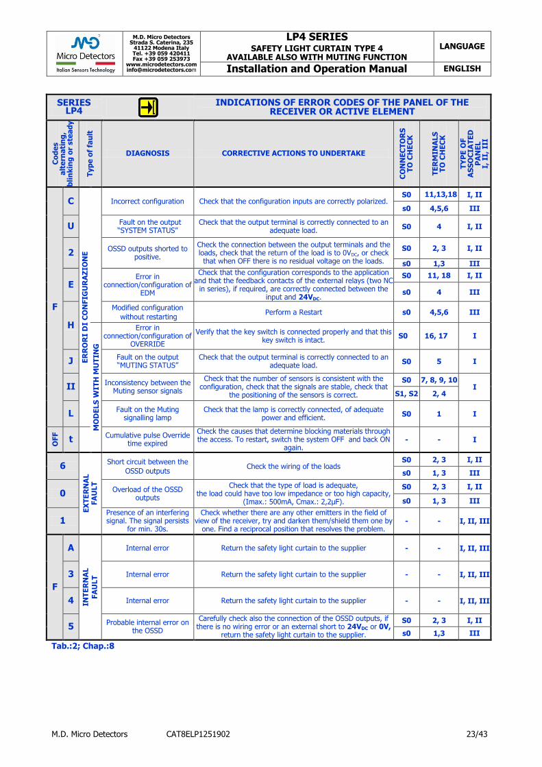
M.D. Micro Detectors Strada S. Caterina, 235
41122 Modena Italy Tel. +39 059 420411 Fax +39 059 253973
www.microdetectors.com [email protected]
LP4 SERIES SAFETY LIGHT CURTAIN TYPE 4
AVAILABLE ALSO WITH MUTING FUNCTION LANGUAGE
Installation and Operation Manual ENGLISH
M.D. Micro Detectors CAT8ELP1251902 23/43
SERIES LP4
INDICATIONS OF ERROR CODES OF THE PANEL OF THE RECEIVER OR ACTIVE ELEMENT
Co
de
s
alt
ern
ati
ng
,
bli
nk
ing
or
ste
ad
y
Typ
e o
f fa
ult
DIAGNOSIS CORRECTIVE ACTIONS TO UNDERTAKE
CO
NN
EC
TO
RS
T
O C
HE
CK
TE
RM
INA
LS
T
O C
HE
CK
TY
PE
OF
AS
SO
CIA
TE
D
PA
NE
L
I, I
I, I
II
F
C
ER
RO
RI
DI
CO
NFIG
UR
AZ
ION
E
Incorrect configuration Check that the configuration inputs are correctly polarized.
S0 11,13,18 I, II
s0 4,5,6 III
U Fault on the output “SYSTEM STATUS”
Check that the output terminal is correctly connected to an adequate load.
S0 4 I, II
2 OSSD outputs shorted to
positive.
Check the connection between the output terminals and the loads, check that the return of the load is to 0VDC, or check that when OFF there is no residual voltage on the loads.
S0 2, 3 I, II
s0 1,3 III
E Error in
connection/configuration of EDM
Check that the configuration corresponds to the application and that the feedback contacts of the external relays (two NC
in series), if required, are correctly connected between the input and 24VDC.
S0 11, 18 I, II
s0 4 III
H
Modified configuration
without restarting Perform a Restart s0 4,5,6 III
MO
DE
LS
WIT
H M
UT
ING
Error in connection/configuration of
OVERRIDE
Verify that the key switch is connected properly and that this key switch is intact.
S0 16, 17 I
J Fault on the output “MUTING STATUS”
Check that the output terminal is correctly connected to an adequate load.
S0 5 I
II Inconsistency between the Muting sensor signals
Check that the number of sensors is consistent with the configuration, check that the signals are stable, check that
the positioning of the sensors is correct.
S0 7, 8, 9, 10 I
S1, S2 2, 4
L Fault on the Muting
signalling lamp Check that the lamp is correctly connected, of adequate
power and efficient. S0 1 I
OFF
t Cumulative pulse Override time expired
Check the causes that determine blocking materials through the access. To restart, switch the system OFF and back ON
again. - - I
6
EX
TE
RN
AL
FA
ULT
Short circuit between the
OSSD outputs Check the wiring of the loads
S0 2, 3 I, II
s0 1, 3 III
0 Overload of the OSSD outputs
Check that the type of load is adequate, the load could have too low impedance or too high capacity,
(Imax.: 500mA, Cmax.: 2,2μF).
S0 2, 3 I, II
s0 1, 3 III
1 Presence of an interfering signal. The signal persists
for min. 30s.
Check whether there are any other emitters in the field of view of the receiver, try and darken them/shield them one by
one. Find a reciprocal position that resolves the problem. - - I, II, III
F
A
INT
ER
NA
L
FA
ULT
Internal error Return the safety light curtain to the supplier - - I, II, III
3 Internal error Return the safety light curtain to the supplier - - I, II, III
4 Internal error Return the safety light curtain to the supplier - - I, II, III
5 Probable internal error on
the OSSD
Carefully check also the connection of the OSSD outputs, if there is no wiring error or an external short to 24VDC or 0V,
return the safety light curtain to the supplier.
S0 2, 3 I, II
s0 1,3 III
Tab.:2; Chap.:8

M.D. Micro Detectors Strada S. Caterina, 235
41122 Modena Italy Tel. +39 059 420411 Fax +39 059 253973
www.microdetectors.com [email protected]
LP4 SERIES SAFETY LIGHT CURTAIN TYPE 4
AVAILABLE ALSO WITH MUTING FUNCTION LANGUAGE
Installation and Operation Manual ENGLISH
M.D. Micro Detectors CAT8ELP1251902 24/43
SERIES LP4
INDICATIONS OF THE EMITTER PANEL
Indication of the LEDs and Display starting from the moment of power on:
initial Test period, indication of the setting and operation, fault.
Time since power on (s) 0…5 5…∞ Fault signalling
Ref.
Co
lou
r
Fu
ncti
on
TEST LED
Indication of the setting:
LED OFF or ON Type of fault
Not
defined Internal Internal
Range
selection Internal
1 RD FAULT
- -
2 GN ON
- System
OK
3 OG RANGE
Low Range
High Range
4 YE TEST
Not in Test
Test in progress
Panel IV Corrective actions to undertake
Wait or Restart
Send to supplier
Send to supplier
Check wiring
Send to supplier
MODELS LP4E/**-***, L, S, M4, M4L
Tab.:3; Chap.:8

M.D. Micro Detectors Strada S. Caterina, 235
41122 Modena Italy Tel. +39 059 420411 Fax +39 059 253973
www.microdetectors.com [email protected]
LP4 SERIES SAFETY LIGHT CURTAIN TYPE 4
AVAILABLE ALSO WITH MUTING FUNCTION LANGUAGE
Installation and Operation Manual ENGLISH
M.D. Micro Detectors CAT8ELP1251902 25/43
9.0 LISTS OF AVAILABLE MODELS AND MAIN CHARACTERISTICS
LP4 SERIES SAFETY LIGHT CURTAINS FOR HAND PROTECTION WITH RESOLUTION 30mm, FUNCTION
OF INTEGRATED MUTING BY EXTERNAL SENSORS
MODELS PAIRED
LP4 ER / 30 - 030 to 120 M4 Model
variables
FUNCTIONS: Muting and Override complete and selectable; heights from 300mm to 1200mm; selectable restart and EDM; selectable standard ranges; M23, 19 pole receiver connector and two M12, 5 poles
MODELS
BE
AM
S
RE
SO
LU
TIO
N
OP
TIC
AL
HE
IGH
T
HO
US
ING
HE
IGH
T
RA
NG
E
SE
LE
CT
ION
RE
SP
ON
SE
TIM
E
PFH
d
DC
avg
MT
TF
d
CC
F
Connectors
DESCRIPTION Em. Rec.
No. mm mm R/E mm m ms Fail./h % years score No., Ø, Poles
LP4ER/30-030M4 16 30 310 458 0 to 6
1 to 16 12 9,06E-09 98,24 100 80 M12-5
M23-19 2x
M12-5
MUTING
Two-way 2-4 beams. Mono-directional 2 beams.
Configurations:Tab.:4; Chap.:6
RECEIVER Dimensions: Fig.:1; Chap.:10
Connections:Tab.:3 (b); Chap.:6 Panel: I: Tab.:1; Chap.:8
EMITTER
Dimensions: Fig.:2; Chap.:10 Connections: Tab.:1; Chap.:6
Panel: IV: Tab.:3; Chap.:8
423
LP4ER/30-045M4 24 30 460 608 0 to 6
1 to 16 15 9,89E-06 98,35 100 80 M12-5
M23-19 2x
M12-5 573
LP4ER/30-060M4 32 30 610 758 0 to 6
1 to 16 18 1.09E-08 98,44 100 80 M12-5
M23-19 2x
M12-5 723
LP4ER/30-075M4 40 30 760 908 0 to 6
1 to 16 21 1,18E-08 98,50 100 80 M12-5
M23-19 2x
M12-5 873
LP4ER/30-090M4 48 30 910 1058 0 to 6
1 to 16 24 1,28E-08 98,55 100 80 M12-5
M23-19 2x
M12-5 1023
LP4ER/30-105M4 56 30 1060 1173 0 to 6
1 to 16 27 1,37E-08 98,56 100 80 M12-5
M23-19 2x
M12-5 1058
LP4ER/30-120M4 64 30 1210 1358 0 to 6
1 to 16 30 1,46E-08 98,63 100 80 M12-5
M23-19 2x
M12-5 1323
APPLICATION
Two-way Muting with two pairs of parallel sensors and check on
sequence or simultaneity.
Two-way Muting with a pair of crossed sensors and check on
simultaneity only.
Mono-directional Muting with a pair of parallel sensors and check
on simultaneity.
Mono-directional Muting with a pair of crossed sensors and check
on simultaneity.
Tab.:1; Chap.:9

M.D. Micro Detectors Strada S. Caterina, 235
41122 Modena Italy Tel. +39 059 420411 Fax +39 059 253973
www.microdetectors.com [email protected]
LP4 SERIES SAFETY LIGHT CURTAIN TYPE 4
AVAILABLE ALSO WITH MUTING FUNCTION LANGUAGE
Installation and Operation Manual ENGLISH
M.D. Micro Detectors CAT8ELP1251902 26/43
LP4 SERIES SAFETY LIGHT CURTAINS FOR HAND PROTECTION
WITH RESOLUTION 40mm LONG RANGE
MODELS PAIRED
LP4 ER / 40 - 060 090 120 L Model
variables
FUNCTIONS: heights from 600mm to 1200mm; selectable restart and EDM; selectable long ranges; M23, 19 pole receiver connector
MODELS
BE
AM
S
RE
SO
LU
TIO
N
OP
TIC
AL
HE
IGH
T
HO
US
ING
HE
IGH
T
RA
NG
E
SE
LE
CT
ION
RE
SP
ON
SE
TIM
E
PFH
d
DC
avg
MT
TF
d
CC
F Connectors
DESCRIPTION Em. Rec.
No. mm mm R=E mm m ms Fail./h % years score No., Ø, Poles
LP4ER/40-060L 30 40 610 723 8 to 30 18 to 60
17 1,02E-08 98,37 100 80 M12-5 M23-19 Receiver
Dimensions: Fig.:3; Chap.:10 Connections: Tab.:3 (a); Chap.:6
Panel: II: Tab.:1; Chap.:8 Emitter
Dimensions: Fig.:4; Chap.:10 Connections: Tab.:1; Chap.:6
Panel: IV: Tab.:3; Chap.:8
LP4ER/40-090L 45 40 910 1023 8 to 30 18 to 60
23 1,17E-08 98,49 100 80 M12-5 M23-19
LP4ER/40-120L 60 40 1210 1323 8 to 30 18 to 60
28,5 1,32E-08 98,57 100 80 M12-5 M23-19
APPLICATION
Tab.:2; Chap.:9

M.D. Micro Detectors Strada S. Caterina, 235
41122 Modena Italy Tel. +39 059 420411 Fax +39 059 253973
www.microdetectors.com [email protected]
LP4 SERIES SAFETY LIGHT CURTAIN TYPE 4
AVAILABLE ALSO WITH MUTING FUNCTION LANGUAGE
Installation and Operation Manual ENGLISH
M.D. Micro Detectors CAT8ELP1251902 27/43
LP4 SERIES SAFETY LIGHT CURTAINS FOR HAND PROTECTION WITH RESOLUTION 40mm,
FUNCTION OF INTEGRATED MUTING BY EXTERNAL SENSORS
MODELS PAIRED
LP4 ER / 40 - 030 to 180 M4 Model
variables
FUNCTIONS: Muting and Override complete and selectable; heights from 300mm to 1200mm; selectable restart and EDM; selectable standard ranges; M23, 19 pole receiver connector and two M12, 5 poles
MODELS
BE
AM
S
RE
SO
LU
TIO
N
OP
TIC
AL
HE
IGH
T
HO
US
ING
HE
IGH
T
RA
NG
E
SE
LE
CT
ION
RE
SP
ON
SE
TIM
E
PFH
d
DC
avg
MT
TF
d
CC
F Connectors
DESCRIPTION Em. Rec.
No. mm mm R/E mm m ms Fail./h % years score No., Ø, Poles
LP4ER/40-030M4 10 40 310 458 0 to 6
1 to 16 9,5 8,71E-09 98,19 100 80 M12-5
M23-19 2x
M12-5
MUTING
Two-way 2-4 beams. Mono-directional 2 beams.
Configurations: Tab.:4; Chap.:6
RECEIVER Dimensions: Fig.:1; Chap.:10
Connections:Tab.:3 (b);Chap.:6 Panel: I: Tab.:1; Chap.:8
EMITTER
Dimensions: Fig.:2; Chap.:10 Connections: Tab.:1; Chap.:6
Panel: IV: Tab.:3; Chap.:8
423
LP4ER/40-045M4 15 40 460 608 0 to 6
1 to 16 11 9,45E-09 98,29 100 80 M12-5
M23-19 2x
M12-5 573
LP4ER/40-060M4 20 40 610 758 0 to 6
1 to 16 13 1,02E-08 98,37 100 80 M12-5
M23-19 2x
M12-5 723
LP4ER/40-075M4 25 40 750 908 0 to 6
1 to 16 15 1,10E-08 98,44 100 80 M12-5
M23-19 2x
M12-5 873
LP4ER/40-090M4 30 40 910 1058 0 to 6
1 to 16 17 1,17E-08 98,49 100 80 M12-5
M23-19 2x
M12-5 1023
LP4ER/40-105M4 35 40 1060 1208 0 to 6
1 to 16 19 1,25E-08 98,53 100 80 M12-5
M23-19 2x
M12-5 1173
LP4ER/40-120M4 40 40 1210 1208 0 to 6
1 to 16 21 1,32E-08 98,57 100 80 M12-5
M23-19 2x
M12-5 1173
LP4ER/40-135M4 45 40 1360 1508 0 to 6
1 to 16 23 1,40E-08 98,60 100 80 M12-5
M23-19 2x
M12-5 1473
LP4ER/40-150M4 50 40 1510 1658 0 to 6
1 to 16 25 1,47E-08 98,63 100 80 M12-5
M23-19 2x
M12-5 1623
LP4ER/40-165M4 55 40 1660 1808 0 to 6
1 to 16 27 1,55E-08 98,65 100 80 M12-5
M23-19 2x
M12-5 1773
LP4ER/40-180M4 60 40 1810 1958 0 to 6
1 to 16 28,5 1,62E-08 98,67 100 80 M12-5
M23-19 2x
M12-5 1923
APPLICATION
Two-way Muting with two pairs of parallel sensors and check on
sequence or simultaneity.
Two-way Muting with a pair of crossed sensors and check on
simultaneity only.
Mono-directional Muting with a pair of parallel sensors and check
on simultaneity.
Mono-directional Muting with a pair of crossed sensors and check
on simultaneity.
Tab.:3; Chap.:9

M.D. Micro Detectors Strada S. Caterina, 235
41122 Modena Italy Tel. +39 059 420411 Fax +39 059 253973
www.microdetectors.com [email protected]
LP4 SERIES SAFETY LIGHT CURTAIN TYPE 4
AVAILABLE ALSO WITH MUTING FUNCTION LANGUAGE
Installation and Operation Manual ENGLISH
M.D. Micro Detectors CAT8ELP1251902 28/43
LP4 SERIES SAFETY LIGHT CURTAINS FOR HAND PROTECTION WITH RESOLUTION 40mm,
LONG RANGE AND FUNCTION OF INTEGRATED MUTING BY EXTERNAL SENSORS MODELS PAIRED
LP4 ER / 40 - 060 090 120 M4 L Model
variables
FUNCTIONS: Muting and Override complete and selectable; heights from 300mm to 1200mm; selectable long ranges; selectable restart and EDM; M23, 19 pole receiver connector and two M12, 5 poles.
MODELS
BE
AM
S
RE
SO
LU
TIO
N
OP
TIC
AL
HE
IGH
T
HO
US
ING
HE
IGH
T
RA
NG
E
SE
LE
CT
ION
RE
SP
ON
SE
TIM
E
PFH
d
DC
avg
MT
TF
d
CC
F Connectors
DESCRIPTION Em. Rec.
No. mm mm R/E mm
m ms Fail./h % years score No., Ø, Poles
LP4ER/40-060M4L 20 40 610 758
8 to 30 18 to 60
13 1,02E-08 98,37 100 80 M12-5 M23-19
2x M12-5
MUTING Two-way 2-4 beams.
Mono-directional 2 beams. Configurations:Tab.:4; Chap.:6
RECEIVER Dimensions: Fig.:1; Chap.:10
Connections:Tab.:3 (b);Chap.:6 Panel: I: Tab.:1; Chap.:8
EMITTER Dimensions: Fig.:2; Chap.:10 Connections: Tab.:1; Chap.:6
Panel: IV: Tab.:3; Chap.:8
723
LP4ER/40-090M4L 30 40 910 1058
8 to 30 18 to 60
23 1,17E-08 98,49 100 80 M12-5 M23-19
2x M12-5 1023
LP4ER/40-120M4L 40 40 1210 1358
8 to 30 18 to 60
28,5 1,32E-08 98,57 100 80 M12-5 M23-19
2x M12-5 1323
APPLICATION
Two-way Muting with two pairs of parallel sensors and check on
sequence or simultaneity.
Two-way Muting with a pair of crossed sensors and check on
simultaneity only.
Mono-directional Muting with a pair of parallel sensors and check
on simultaneity.
Mono-directional Muting with a pair of crossed sensors and check
on simultaneity.
Tab.:4; Chap.:9

M.D. Micro Detectors Strada S. Caterina, 235
41122 Modena Italy Tel. +39 059 420411 Fax +39 059 253973
www.microdetectors.com [email protected]
LP4 SERIES SAFETY LIGHT CURTAIN TYPE 4
AVAILABLE ALSO WITH MUTING FUNCTION LANGUAGE
Installation and Operation Manual ENGLISH
M.D. Micro Detectors CAT8ELP1251902 29/43
LP4 SERIES SAFETY LIGHT CURTAINS FOR LIMB PROTECTION WITH RESOLUTION 90mm,
AND FUNCTION OF INTEGRATED MUTING BY EXTERNAL SENSORS MODELS PAIRED
LP4 ER / 90 - 030 to 180 M4 Model
variables
FUNCTIONS: Muting and Override complete and selectable; heights from 300mm to 1200mm; standard ranges; selectable restart and EDM; M23, 19 pole receiver connector and two M12, 5 poles.
MODELS
BE
AM
S
RE
SO
LU
TIO
N
OP
TIC
AL
HE
IGH
T
HO
US
ING
HE
IGH
T
RA
NG
E
SE
LE
CT
ION
RE
SP
ON
SE
TIM
E
PFH
d
DC
avg
MT
TF
d
CC
F Connectors
DESCRIPTION Em. Rec.
No. mm mm R/E mm m ms Fail./h % years score No., Ø, Poles
LP4ER/90-030M4 5 90 310 458 0 to 6
1 to 16 7 8,91E-09 98,22 100 80 M12-5
M23-19 2x
M12-5
MUTING Two-way 2-4 beams.
Mono-directional 2 beams. Config.:Tab.:4;Chap.:6
RECEIVER
Dimensions: Fig.:1; Chap.:10 Connections:Tab.:3(b);Chap.:6
Panel: I: Tab.:1; Chap.:8
EMITTER Dimensions: Fig.:2; Chap.:10 Connections Tab.:1; Chap.:6 Panel: IV: Tab.:3; Chap.:8
423
LP4ER/90-045M4 7 90 460 608 0 to 6
1 to 16 8 9,48E-09 98,30 100 80 M12-5
M23-19 2x
M12-5 573
LP4ER/90-060M4 9 90 610 758 0 to 6
1 to 16 9 1,01E-08 98,36 100 80 M12-5
M23-19 2x
M12-5 723
LP4ER/90-075M4 11 90 760 908 0 to 6
1 to 16 10 1,06E-08 98,41 100 80 M12-5
M23-19 2x
M12-5 873
LP4ER/90-090M4 13 90 910 1058 0 to 6
1 to 16 10,5 1,12E-08 98,46 100 80 M12-5
M23-19 2x
M12-5 1023
LP4ER/90-105M4 15 90 1060 1208 0 to 6
1 to 16 11 1,18E-08 98,50 100 80 M12-5
M23-19 2x
M12-5 1173
LP4ER/90-120M4 17 90 1210 1358 0 to 6
1 to 16 12 1,24E-08 98,53 100 80 M12-5
M23-19 2x
M12-5 1323
LP4ER/90-135M4 19 90 1360 1508 0 to 6
1 to 16 13 1,29E-08 98,56 100 80 M12-5
M23-19 2x
M12-5 1473
LP4ER/90-150M4 21 90 1510 1658 0 to 6
1 to 16 13,5 1,35E-08 98,58 100 80 M12-5
M23-19 2x
M12-5 1623
LP4ER/90-165M4 23 90 1660 1808 0 to 6
1 to 16 14 1,41E-08 98,61 100 80 M12-5
M23-19 2x
M12-5 1773
LP4ER/90-180M4 25 90 1810 1958 0 to 6
1 to 16 15 1,47E-08 98,63 100 80 M12-5
M23-19 2x
M12-5 1923
APPLICATION
Two-way Muting with two pairs of parallel sensors and check on
sequence or simultaneity.
Two-way Muting with a pair of crossed sensors and check on
simultaneity only.
Mono-directional Muting with a pair of parallel sensors and check
on simultaneity.
Mono-directional Muting with a pair of crossed sensors and check
on simultaneity.
Tab.:5; Chap.:9

M.D. Micro Detectors Strada S. Caterina, 235
41122 Modena Italy Tel. +39 059 420411 Fax +39 059 253973
www.microdetectors.com [email protected]
LP4 SERIES SAFETY LIGHT CURTAIN TYPE 4
AVAILABLE ALSO WITH MUTING FUNCTION LANGUAGE
Installation and Operation Manual ENGLISH
M.D. Micro Detectors CAT8ELP1251902 30/43
LP4 SERIES SAFETY LIGHT GRID WITH MULTI-BEAM OPTICS FOR ACCESS PROTECTION
MODELS PAIRED
LP4 ER / 0A 0B 0C - 050 080 090 L S Model
variables
FUNCTIONS: 2, 3, 4 beams; standard, long and super ranges; selectable restart and EDM; M23, 19 pole or M12, 8 pole receiver connector.
MODELS
BE
AM
S
PIT
CH
OP
TIC
AL
HE
IGH
T
HO
US
ING
HE
IGH
T
RA
NG
E
SE
LE
CT
ION
RE
SP
ON
SE
TIM
E
PFH
d
DC
avg
MT
TF
d
CC
F Connectors
DESCRIPTION Em. Rec.
No. mm mm R=E mm m ms Fail./h % years score No., Ø, Poles
LP4ER/0A-050 2 500 510 723 0 to 6 1 to 16
7 7,53E-09 97,94 100 80 M12-5 M23-19
RECEIVER Dimensions: Fig.:3; Chap.:10
Connections:Tab.:3(a);Chap.:6 Panel: II: Tab.:1; Chap.:8
EMITTER Dimensions: Fig.:4; Chap.:10 Connections Tab.:1; Chap.:6 Panel: IV: Tab.:3; Chap.:8
LP4ER/0B-080 3 400 810 1023 0 to 6 1 to 16
7 7,70E-09 97,99 100 80 M12-5 M23-19
LP4ER/0C-090 4 300 910 1123 0 to 6 1 to 16
7 7,87E-09 98,03 100 80 M12-5 M23-19
LP4ER/0A-050L 2 500 510 723 8 to 30 18 to 60
7 7,53E-09 97,94 100 80 M12-5 M23-19
LP4ER/0B-080L 3 400 810 1023 8 to 30 18 to 60
7 7,70E-09 97,99 100 80 M12-5 M23-19
LP4ER/0C-090L 4 300 910 1123 8 to 30 18 to 60
7 7,87E-09 98,03 100 80 M12-5 M23-19
LP4ER/0A-050L12 2 500 510 723 8 to 30 18 to 60
7 7,53E-09 97,94 100 80 M12-5 M12-8 RECEIVER
Dimensions: Fig.:4; Chap.:10 Connections: Tab.:7; Chap.:6
Panel: II; Tab.:1; Chap.:8
EMITTER Dimensions: Fig.:4; Chap.:10 Connections Tab.:1; Chap.:6 Panel: IV: Tab.:3; Chap.:8
LP4ER/0B-080L12 3 400 810 1023 8 to 30 18 to 60
7 7,70E-09 97,99 100 80 M12-5 M12-8
LP4ER/0C-090L12 4 300 910 1123 8 to 30 18 to 60
7 7,87E-09 98,03 100 80 M12-5 M12-8
APPLICATION
0C
Tab.:6; Chap.:9

M.D. Micro Detectors Strada S. Caterina, 235
41122 Modena Italy Tel. +39 059 420411 Fax +39 059 253973
www.microdetectors.com [email protected]
LP4 SERIES SAFETY LIGHT CURTAIN TYPE 4
AVAILABLE ALSO WITH MUTING FUNCTION LANGUAGE
Installation and Operation Manual ENGLISH
M.D. Micro Detectors CAT8ELP1251902 31/43
LP4 SERIES SAFETY LIGHT GRID WITH MULTI-BEAM OPTICS FOR ACCESS PROTECTION
AND FUNCTION OF INTEGRATED MUTING BY EXTERNAL SENSORS MODELS PAIRED
LP4 ER / 0A 0B 0C - 050 080 090 M4 L Model
variables
FUNCTIONS: 2, 3, 4 beams; heights from 300mm to 1200mm; standard ranges; selectable restart and EDM; M23, 19 pole receiver connector and two M12, 5 poles.
MODELS
BE
AM
S
PIT
CH
OP
TIC
AL
HE
IGH
T
HO
US
ING
HE
IGH
T
RA
NG
E
SE
LE
CT
ION
RE
SP
ON
SE
TIM
E
PFH
d
DC
avg
MT
TF
d
CC
F Connectors
DESCRIPTION Em. Rec.
No. mm mm R/E mm
m ms Fail./h % years score No., Ø, Poles
LP4ER/0A-050M4 2 500 510 758 0 to 6
1 to 16 7 7,53E-09 97,84 100 80 M12-5
M23-19 2x
M12-5 MUTING
Two-way 2-4 beams. Mono-directional 2 beams.
Configurations:Tab.:4;Chap.:6
RECEIVER Dimensions: Fig.:1; Chap.:10
Connections:Tab.:3(b);Chap.:6 Panel: I: Tab.:1; Chap.:8
EMITTER
Dimensions: Fig.:2; Chap.:10 Connections Tab.:1; Chap.:6 Panel: IV: Tab.:3; Chap.:8
723
LP4ER/0B-080M4 3 400 810 1058 0 to 6
1 to 16 7 7,70E-09 97,99 100 80 M12-5
M23-19 2x
M12-5 1023
LP4ER/0C-090M4 4 300 910 1158 0 to 6
1 to 16 7 7,87E-09 98,03 100 80 M12-5
M23-19 2x
M12-5 1123
LP4ER/0A-050M4L 2 500 510 758 8 to 30
18 to 60 7 7,53E-09 97,84 100 80 M12-5
M23-19 2xM12-
5 723
LP4ER/0B-080M4L 3 400 810 1058 8 to 30
18 to 60 7 7,70E-09 97,99 100 80 M12-5
M23-19 2x
M12-5 1023
LP4ER/0C-090M4L 4 300 910 1158 8 to 30
18 to 60 7 7,87E-09 98,03 100 80 M12-5
M23-19 2x
M12-5 1123
APPLICATION
Two-way Muting with two pairs of parallel sensors and check on
sequence or simultaneity.
Two-way Muting with a pair of crossed sensors and check on
simultaneity only.
Mono-directional Muting with a pair of parallel sensors and check
on simultaneity.
Mono-directional Muting with a pair of crossed sensors and check
on simultaneity.
Tab.:7; Chap.:9

M.D. Micro Detectors Strada S. Caterina, 235
41122 Modena Italy Tel. +39 059 420411 Fax +39 059 253973
www.microdetectors.com [email protected]
LP4 SERIES SAFETY LIGHT CURTAIN TYPE 4
AVAILABLE ALSO WITH MUTING FUNCTION LANGUAGE
Installation and Operation Manual ENGLISH
M.D. Micro Detectors CAT8ELP1251902 32/43
LP4 SERIES SAFETY LIGHT GRID WITH MULTI-BEAM OPTICS FOR ACCESS PROTECTION
E/R ACTIVE ELEMENT AND PASSIVE REFLECTOR ELEMENT MODELS PAIRED
LP4 PF / 0A 0B 0C - 050 080 090 Model
variables
FUNCTIONS: 2, 3, 4 beams; heights from 300mm to 900mm; standard range; selectable restart and EDM; active element M12, 8 pole connector
MODELS
BE
AM
S
PIT
CH
OP
TIC
AL
HE
IGH
T
HO
US
ING
HE
IGH
T
RA
NG
E
RE
SP
ON
SE
TIM
E
PFH
d
DC
avg
MT
TF
d
CC
F Connectors
DESCRIPTION P (Ref)
F (E/R)
No. mm mm F=P mm m ms Fail./h % years score No., Ø, Poles
LP4PF/0A-050 2 500 510 723 0 to 6 ≤7 4,83E-09 98,14 100 80 - M12-8 ACTIVE ELEMENT Dimensions: Fig.:5; Chap.:10 Connections: Tab.:7; Chap.:6 Panel: III; Tab.:1; Chap.:8
PASSIVE REFLECTOR
Dimensions: Fig.:6; Chap.:10
LP4PF/0B-080 3 400 810 1023 0 to 6 ≤7 4,92E-09 98,16 100 80 - M12-8
LP4PF/0C-090 4 300 910 1123 0 to 6 ≤7 5,01E-09 98,19 100 80 - M12-8
APPLICATION
0A 0B 0C
Tab.:8; Chap.:9

M.D. Micro Detectors Strada S. Caterina, 235
41122 Modena Italy Tel. +39 059 420411 Fax +39 059 253973
www.microdetectors.com [email protected]
LP4 SERIES SAFETY LIGHT CURTAIN TYPE 4
AVAILABLE ALSO WITH MUTING FUNCTION LANGUAGE
Installation and Operation Manual ENGLISH
M.D. Micro Detectors CAT8ELP1251902 33/43
LP4 SERIES SAFETY LIGHT GRID WITH MULTI-BEAM OPTICS WITH PASSIVE REFLECTOR FOR ACCESS
PROTECTION AND FUNCTION OF INTEGRATED MUTING BY REFLEX-TYPE EXTERNAL SENSORS
MODELS PAIRED
LP4 PT / 0A 0B 0C - 050 080 090 M4 Model
variables
FUNCTIONS: 2, 3, 4 beams; heights from 300mm to 1200mm; standard range; selectable restart and EDM; M23, 19 pole active element connector and two M12, 5 poles.
MODELS
BE
AM
S
PIT
CH
OP
TIC
AL
HE
IGH
T
HO
US
ING
HE
IGH
T
RA
NG
E
RE
SP
ON
SE
TIM
E
PFH
d
DC
avg
MT
TF
d
CC
F Connectors
DESCRIPTION P (Ref)
T (E/R)
No. mm mm T/P mm
m ms Fail./h % years score No., Ø, Poles
LP4PT/0A-050M4 2 500 510 758
0 to 6 10 4,83E-09 98,14 100 80 - M23-19
2x M12-5
MUTING Two-way 2-4 beams.
Mono-directional 2 beams. Configurations:Tab.:4; Chap.:6
ACTIVE ELEMENT Dimensions: Fig.:7; Chap.:10
Connections:Tab.:3 (b);Chap.:6 Panel: I: Tab.:1; Chap.:8 PASSIVE REFLECTOR
Dimensions: Fig.:8; Chap.:10
723
LP4PT/0B-080M4 3 400 810 1058
0 to 6 10 4,92E-09 98,16 100 80 - M23-19
2x M12-5 1023
LP4PT/0C-090M4 4 300 910 1158
0 to 6 10 5,01E-09 98,19 100 80 - M23-19
2x M12-5 1123
APPLICATION
Two-way Muting with two pairs of parallel sensors and check on
sequence or simultaneity.
Two-way Muting with a pair of crossed sensors and check on
simultaneity only.
Mono-directional Muting with a pair of parallel sensors and check
on simultaneity.
Mono-directional Muting with a pair of crossed sensors and check
on simultaneity.
Tab.:9; Chap.:9

M.D. Micro Detectors Strada S. Caterina, 235
41122 Modena Italy Tel. +39 059 420411 Fax +39 059 253973
www.microdetectors.com [email protected]
LP4 SERIES SAFETY LIGHT CURTAIN TYPE 4
AVAILABLE ALSO WITH MUTING FUNCTION LANGUAGE
Installation and Operation Manual ENGLISH
M.D. Micro Detectors CAT8ELP1251902 34/43
LP4 SERIES SAFETY LIGHT GRID WITH MULTI-BEAM OPTICS WITH PASSIVE REFLECTOR FOR ACCESS
PROTECTION AND FUNCTION OF INTEGRATED MUTING BY TWO REFLEX-TYPE EXTERNAL SENSORS
MODELS PAIRED
LP4 PT / 0A 0B 0C - 050 080 090 M2 Model
variables
FUNCTIONS: 2, 3, 4 beams; heights from 300mm to 1200mm; standard range; selectable restart and EDM; M23, 19 pole active element connector.
MODELS
BE
AM
S
PIT
CH
OP
TIC
AL
HE
IGH
T
HO
US
ING
HE
IGH
T
RA
NG
E
RE
SP
ON
SE
TIM
E
PFH
d
DC
avg
MT
TF
d
CC
F Connectors
DESCRIPTION P (Ref)
T (E/R)
No. mm mm T=P mm
m ms Fail./h % years score No., Ø, Poles
LP4PT /0A-050M2 2 500 510 723 0 to 6 10 4,83E-09 98,14 100 80 - M23-19 MUTING
Mono-directional 2 beams. Configurations: Tab.:4; Chap.:6
ACTIVE ELEMENT Dimensions: Fig.:9; Chap.:10
Connections: Tab.:3 (d); Chap.:6
Panel: I: Tab.:1; Chap.:8 PASSIVE REFLECTOR
Dimensions: Fig.:10; Chap.:10
LP4PT /0B-080M2 3 400 810 1023 0 to 6 10 4,92E-09 98,16 100 80 - M23-19
LP4PT /0C-090M2 4 300 910 1123 0 to 6 10 5,01E-09 98,19 100 80 - M23-19
APPLICATION
Mono-directional Muting by pair of crossed sensors (reflex) whose inputs are accessible via the M23 connector, check on simultaneity only.
Tab.:10; Chap.:9

M.D. Micro Detectors Strada S. Caterina, 235
41122 Modena Italy Tel. +39 059 420411 Fax +39 059 253973
www.microdetectors.com [email protected]
LP4 SERIES SAFETY LIGHT CURTAIN TYPE 4
AVAILABLE ALSO WITH MUTING FUNCTION LANGUAGE
Installation and Operation Manual ENGLISH
M.D. Micro Detectors CAT8ELP1251902 35/43
10.0 MECHANICAL DIMENSIONS OF THE LIGHT CURTAINS AND STANDARD ACCESSORIES
SAFETY LIGHT CURTAINS AND MULTI-BEAM LIGHT GRIDS WITH INTEGRATED MUTING FUNCTION ENABLED BY FOUR SENSOR INPUTS AVAILABLE ON TWO FIVE-PIN M12 FEMALE CONNECTORS.
MECHANICAL DIMENSIONS See also
Chap.:9; Tab.:1,3,4,5,7
Fig.:1; Chap.:10 LP4R/**-***M4# Receivers with Muting, standard or long range
Fig.:2; Chap.:10 LP4E/0#-***# Emitter, standard or long range
RESOLUTIONS 30; 40; 90 MULTI-BEAM
MODELS LP4ER/**-***M4# LP4ER/*#-
***M4 LP4ER/*#-
***M4L
TABLES OF CHAPTER 9 1; 3; 4; 5 7 7
HEIGHT (cm) 030 045 060 075 090 105 120 135 150 165 180 050 080 090 050 080 090
LP4R 1 L1 Housing height 458 608 758 908 1058 1208 1358 1508 1658 1808 1958 758 1058 1158 758 1058 1158
LP4E 2 L1 Housing height 423 573 722 873 1023 1173 1323 1473 1623 1773 1923 723 1023 1123 723 1023 1123
LP4ER 1; 2 L2 Protected area 310 460 610 760 910 1060 1210 1360 1510 1660 1810 - - - - - -
LP4ER 1; 2 Number of optics - 2 3 4 2 3 4
LP4ER 1; 2 Resolution / Pitch 30 ; 40 ; 90 500 400 300 500 400 300
LP4ER 1; 2 L3 Beam 1 position 72 120 76
LP4R 1 L4 Base 60
LP4E 2 L4 Base 25
LP4R 1 L5 Height pin C 18 (M23; 19 poles)
LP4E 2 L5 Height pin C 14 (M12; 5 poles)
LP4R 1 L6 Encumbrance conn. with connector C: M23 straight; 120 (not screwed); 110 (screwed) and cable bent 90°
LP4E 2 L6 Encumbrance conn. with connector C: M12 straight; 60 (not screwed); 53 (screwed) and cable bent 90°
LP4R 1 P Panel I (see Tab.:1; Chap.:8)
LP4E 2 P Panel IV (see Tab.:3; Chap.:8)
All dimensions in mm.

M.D. Micro Detectors Strada S. Caterina, 235
41122 Modena Italy Tel. +39 059 420411 Fax +39 059 253973
www.microdetectors.com [email protected]
LP4 SERIES SAFETY LIGHT CURTAIN TYPE 4
AVAILABLE ALSO WITH MUTING FUNCTION LANGUAGE
Installation and Operation Manual ENGLISH
M.D. Micro Detectors CAT8ELP1251902 36/43
SAFETY LIGHT CURTAINS AND MULTI-BEAM LIGHT GRIDS WITHOUT MUTING FUNCTION
MECHANICAL DIMENSIONS See also
Chap.:9; Tab.:2, 6
Fig.:3; Chap.:10 LP4R/40-***# LP4R/0#-***#
Receivers with standard range
Fig.:4; Chap.:10 LP4R/0#-***L12
LP4E/40-***# Receivers with standard, extended Emitters with standard, extended
RESOLUTION 40 MULTI-BEAM MULTI-BEAM (s0:M12)
MODELS LP4ER/40-***L LP4ER/0#-*** LP4ER/*#-***###
TABLES OF CHAPTER 9 2 6 6
HEIGHT (cm) 060 090 120 0A-050 0B-080 0C-090 050 080 090
LP4ER 3; 4 L1 Housing height 723 1023 1323 723 1023 1123 723 1023 1123
LP4ER 3; 4 L2 Protected area 610 910 1210 510 810 910 510 810 910
LP4ER 3; 4 Number of optics - - - 2 3 4 2 3 4
LP4ER 3; 4 Resolution / Pitch 40 500 400 300 500 400 300
LP4ER 3; 4 L3 Beam 1 position 76 120 76
LP4ER 3; 4 L4 Base 25
LP4R 3 L5 Height pin C 18 (M23; 19 poles) 14 (M12; 8 poles)
LP4E 4 L5 Height pin C 14 (M12; 5 poles)
LP4R 3 L6 Encumbrance conn. with connector C: M23 straight; 120 (to screw); 110 (screwed) and cable bent 90°
LP4E 4 L6 Encumbrance conn. with connector C: M12 straight; 60 (to screw); 53 (screwed) and cable bent 90°
LP4R 3 P Panel II (see Tab.:1; Chap.:8)
LP4E 4 P Panel IV (see Tab.:3; Chap.:8)
Type Fig. Quote
All dimensions in mm.

M.D. Micro Detectors Strada S. Caterina, 235
41122 Modena Italy Tel. +39 059 420411 Fax +39 059 253973
www.microdetectors.com [email protected]
LP4 SERIES SAFETY LIGHT CURTAIN TYPE 4
AVAILABLE ALSO WITH MUTING FUNCTION LANGUAGE
Installation and Operation Manual ENGLISH
M.D. Micro Detectors CAT8ELP1251902 37/43
SAFETY MULTI-BEAM LIGHT GRID CONSISTING OF AN ACTIVE ELEMENT, EQUIPPED WITH A MAIN M12 CONNECTOR AND A PASSIVE REFLECTOR
MECHANICAL DIMENSIONS See also
Chap.:9; Tab.:8
Fig.:5; Chap.:10 LP4F/0#-*** Active Element, Emitter/Receiver
Fig.:6; Chap.:10 LP4P/0#-*** Passive reflector
RESOLUTION MULTI-BEAM MODELS LP4PF/0#-***
HEIGHT (cm) LP4PF/0A-050 LP4PF/0B-080 LP4PF/0C-090
LP4PF 5, 6 L1 Housing height 723 1023 1123
LP4PF 5, 6 Number of optics 2 3 (4 beams, 1 double central) 4
LP4PF 5, 6 Pitch 500 400 300
LP4PF 5, 6 L3 Beam 1 position 76 76 76
LP4PF 5, 6 L4 Base 25
LP4F 5 L5 Height pin C 14 (M12; 8 poles)
LP4F 5 L6 Encumbrance conn. with connector C: M12 straight; 60 (to screw); 53 (screwed) and cable bent 90°
LP4F 5 P Panel III (see Tab.:1; Chap.:8)
Type Fig. Quote
All dimensions in mm.

M.D. Micro Detectors Strada S. Caterina, 235
41122 Modena Italy Tel. +39 059 420411 Fax +39 059 253973
www.microdetectors.com [email protected]
LP4 SERIES SAFETY LIGHT CURTAIN TYPE 4
AVAILABLE ALSO WITH MUTING FUNCTION LANGUAGE
Installation and Operation Manual ENGLISH
M.D. Micro Detectors CAT8ELP1251902 38/43
SAFETY MULTI-BEAM LIGHT GRID CONSISTING OF AN ACTIVE ELEMENT AND A PASSIVE REFLECTOR, WITH INTEGRATED MUTING FUNCTION ACTIVATED BY TWO SENSOR INPUTS
AVAILABLE ON TWO FIVE-PIN M12 FEMALE CONNECTORS
MECHANICAL DIMENSIONS See also
Chap.:9; Tab.:9
Fig.:7; Chap.:10 LP4T/0#-***M4# Active Element, Emitter/Receiver with Muting with four sensors
Fig.:8; Chap.:10 LP4P/0#-*** Passive reflector
RESOLUTION MULTI-BEAM
MODELS LP4PT/0#-***M4
HEIGHT (cm) LP4PT/0A-050M4 LP4PT/0B-080M4 LP4PF/0C-090M4
LP4T 7, 8 L1 Housing height 758 1058 1158
LP4P 8 L1 Housing height 723 1023 1123
LP4PT 7, 8 Number of optics 2 3 (4 beams, 1 double central) 4
LP4PT 7, 8 Pitch 500 400 300
LP4PT 7, 8 L3 Beam 1 position 76 76 76
LP4PF 7 L4 Base 60
LP4PF 8 L4 Base 25
LP4T 7 L5 Height pin C 18 (M23; 19 poles)
LP4F 7 L6 Encumbrance conn. with connector C: M23 straight; 120 (not screwed); 110 (screwed) and cable bent 90°
LP4F 7 P Panel I (see Tab.:1; Chap.:8)
Type Fig. Quote
All dimensions in mm.

M.D. Micro Detectors Strada S. Caterina, 235
41122 Modena Italy Tel. +39 059 420411 Fax +39 059 253973
www.microdetectors.com [email protected]
LP4 SERIES SAFETY LIGHT CURTAIN TYPE 4
AVAILABLE ALSO WITH MUTING FUNCTION LANGUAGE
Installation and Operation Manual ENGLISH
M.D. Micro Detectors CAT8ELP1251902 39/43
SAFETY MULTI-BEAM LIGHT GRID CONSISTING OF AN ACTIVE ELEMENT AND A PASSIVE REFLECTOR, WITH INTEGRATED MUTING FUNCTION ACTIVATED BY TWO SENSOR INPUTS
AVAILABLE ON THE MAIN M23 MALE CONNECTOR
MECHANICAL DIMENSIONS See also
Chap.:9; Tab.:10
Fig.:9; Chap.:10 LP4T/**-***M2 Active Element, Emitter/Receiver with Muting with 2 sensors
Fig.:10; Chap.:10 LP4P/0#-*** Passive reflector
RESOLUTION MULTI-BEAM
MODELS LP4PT/0#-***M2
HEIGHT (cm) LP4PT/0A-050M2 LP4PT/0B-080M2 LP4PF/0C-090M2
LP4PT 9, 10 L1 Housing height 723 1023 1123
LP4PT 9, 10 Number of optics 2 3 (4 beams, 1 double central) 4
LP4PT 9, 10 Pitch 500 400 300
LP4PT 9, 10 L3 Beam 1 position 76 76 76
LP4PF 9, 10 L4 Base 25
LP4T 9 L5 Height pin C 18 (M23; 19 poles)
LP4F 9 L6 Encumbrance conn. with connector C: M23 straight; 120 (not screwed); 110 (screwed) and cable bent 90°
LP4F 9 P Panel I (see Tab.:1; Chap.:8)
Type Fig. Quote
All dimensions in mm.
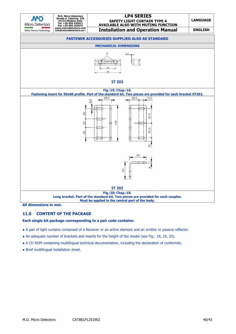
M.D. Micro Detectors Strada S. Caterina, 235
41122 Modena Italy Tel. +39 059 420411 Fax +39 059 253973
www.microdetectors.com [email protected]
LP4 SERIES SAFETY LIGHT CURTAIN TYPE 4
AVAILABLE ALSO WITH MUTING FUNCTION LANGUAGE
Installation and Operation Manual ENGLISH
M.D. Micro Detectors CAT8ELP1251902 40/43
FASTENER ACCESSORIES SUPPLIED ALSO AS STANDARD
MECHANICAL DIMENSIONS
ST 203
Fig.:19; Chap.:10. Fastening insert for 50x60 profile. Part of the standard kit. Two pieces are provided for each bracket ST202.
ST 202 Fig.:20; Chap.:10.
Long bracket. Part of the standard kit. Two pieces are provided for each couples. Must be applied in the central part of the body.
All dimensions in mm.
11.0 CONTENT OF THE PACKAGE
Each single kit package corresponding to a pair code contains:
● A pair of light curtains composed of a Receiver or an active element and an emitter or passive reflector.
● An adequate number of brackets and inserts for the height of the model (see Fig.: 18, 19, 20).
● A CD ROM containing multilingual technical documentation, including the declaration of conformity.
● Brief multilingual installation sheet.

M.D. Micro Detectors Strada S. Caterina, 235
41122 Modena Italy Tel. +39 059 420411 Fax +39 059 253973
www.microdetectors.com [email protected]
LP4 SERIES SAFETY LIGHT CURTAIN TYPE 4
AVAILABLE ALSO WITH MUTING FUNCTION LANGUAGE
Installation and Operation Manual ENGLISH
M.D. Micro Detectors CAT8ELP1251902 41/43
12.0 LIST OF APPLICABLE ACCESSORIES
MODEL DESCRIPTION RELAY INTERFACE MODULES
LP/BOX-1 Module with M23 and M12 male connectors for connection to the receiver and transmitter with extension cords female / female, 24VDC power supply, two NA output (series), one NC output (parallel), panel with Start button, Override command, Muting lamp and fully programmable functions
SB 300 Safety relay module for DIN bar, two 24VDC relays, two output NO contact (single), one output NO contact (series) for EDM. Max. switching voltage 250V AC/DC, contact rating 690VA@230VAC, 72W@24VDC
M23 SUPPLY CONNECTORS WITH CABLE FOR RECEIVERS OR ACTIVE ELEMENTS
CD23M/0R-030A1 M23 connector, straight, 19 poles, female, 3m PVC cable
CD23M/0R-050A1 M23 connector, straight, 19 poles, female, 5m PVC cable
CD23M/0R-100A1 M23 connector, straight, 19 poles, female, 10m PVC cable
CD23M/0R-150A1 M23 connector, straight, 19 poles, female, 15m PVC cable
CD23M/0R-200A1 M23 connector, straight, 19 poles, female, 20m PVC cable
CD23M/0R-300A1 M23 connector, straight, 19 poles, female, 30m PVC cable
CD23M/0R-200A1LM M23 connector, straight, 19 poles, female, PVC cable, length 20m and 2m cable for the Muting lamp
CD23M/0R-300A1LM M23 connector, straight, 19 poles, female, PVC cable, length 30m and 2m cable for the Muting lamp
EXTENSIONS CABLES WITH M23 CONNECTORS FOR INTERCONNECTION
BETWEEN RECEIVERS OR ACTIVE AND MODULES
CDP23/0R-030AC Extension, M23-M23 connectors, straight, 19 poles, female/female, 3m PVC cable
CDP23/0R-050AC Extension, M23-M23 connectors, straight, 19 poles, female/female, 5m PVC cable
CDP23/0R-100AC Extension, M23-M23,connectors, straight, 19 poles, female/female, 10m PVC cable
M12 SUPPLY CONNECTORS WITH CABLE FOR RECEIVERS OR ACTIVE ELEMENTS
CD12M/0E-050A1 M12 connector, straight, 8 poles, female, 5m PVC cable
CD12M/0E-100A1 M12 connector, straight, 8 poles, female, 10m PVC cable
CD12M/0E-150A1 M12 connector, straight, 8 poles, female, 15m PVC cable
CD12M/0E-250A1 M12 connector, straight, 8 poles, female, 25m PVC cable
CD12M/0E-400A1 M12 connector, straight, 8 poles, female, 40m PVC cable
CD12M/0E-050C1 M12 connector, right-angle, 8 poles, female, 5m PVC cable
CD12M/0E-100C1 M12 connector, right-angle, 8 poles, female, 10m PVC cable
CD12M/0E-150C1 M12 connector, right-angle, 8 poles, female, 15m PVC cable
M12 SUPPLY CONNECTORS WITH CABLE FOR EMITTERS
CD12M/0H-050A3 M12 connector, straight, 5 poles, female, 5m PVC cable
CD12M/0H-100A3 M12 connector, straight, 5 poles, female, 10m PVC cable
CD12M/0H-150A3 M12 connector, straight, 5 poles, female, 15m PVC cable
CD12M/0H-250A3 M12 connector, straight, 5 poles, female, 25m PVC cable
CD12M/0H-500A3 M12 connector, straight, 5 poles, female, 50m PVC cable
CD12M/0H-050C3 M12 connector, right-angle, 5 poles, female, 5m PVC cable
CD12M/0H-100C3 M12 connector, right-angle, 5 poles, female, 10m PVC cable
CD12M/0H-150C3 M12 connector, right-angle, 5 poles, female, 15m PVC cable
M12 SUPPLAY CONNECTORS WITH CABLE FOR INTERCONNECTION OF MUTING SENSOR
CD12M/0H-050D1 M12 connector, right-angle, 5 poles, male, 5m PVC cable
EXTENSIONS CABLES WITH M12 CONNECTORS FOR INTERCONNECTION
BETWEEN EMITTERS AND LP/BOX-1 MODULE
CDP12/0H-030AC Extension, M12/M12 connectors, straight, 5 poles, female/female, 3m PVC cable
CDP12/0H-050AC Extension, M12/M12 connectors, straight, 5 poles, female/female, 5m PVC cable
CDP12/0H-100AC Extension, M12/M12 connectors, straight, 5 poles, female/female, 10m PVC cable
CDP12/0H-250AC Extension, M12/M12 connectors, straight, 5 poles, female/female, 25m PVC cable
TEST RODS
ST2230 Test rod Ø 30mm ST2240 Test rod Ø 40mm
BRACKETS
ST 202 4 Kit of 4 long L brackets; see Fig.:20; Chap.:10
ST 203 4 Kit of 4 fixing inserts; see Fig.:19; Chap.:10
ST 203 6 Kit of 6 fixing inserts; see Fig.:19; Chap.:10
VIBRATION DAMPING SUPPORTS
ST VP 4 Kit of 4 vibration-damping supports
ST VP 6 Kit of 6 vibration-damping supports
TRACKING SYSTEM
STL 01 P Specific tracking LASER for alignment of the light curtains with profile 50x60mm
Tab.:1; Chap.:12

M.D. Micro Detectors Strada S. Caterina, 235
41122 Modena Italy Tel. +39 059 420411 Fax +39 059 253973
www.microdetectors.com [email protected]
LP4 SERIES SAFETY LIGHT CURTAIN TYPE 4
AVAILABLE ALSO WITH MUTING FUNCTION LANGUAGE
Installation and Operation Manual ENGLISH
M.D. Micro Detectors CAT8ELP1251902 42/43
13.0 CHECKING THE SYSTEM
13.1 Purpose of the checks.
The purpose of the checks described below is to confirm the safety requirements of the national or international prescriptions, particularly the safety requirements of the Machinery Directive or the Directive for operators of work equipment (conformity with EU directives). These checks are also for detecting interference on the protection effect caused by undesired sources of light, including sensors of the same type and in general by photoelectric sensors, reflections and other particular environmental factors. These checks must necessarily be carried out.
13.2 Checks prior to commissioning
● It must be possible to enter the danger area only via a route that breaks the beam of light between the projector and the receiver. ● It must be impossible to climb over, crawl under or be able to avoid the optical beam between the projector and receiver. ● It must not be possible to stop inside the protected area without this condition being detected. ● It must not be possible to operate the system start/restart controls from within the protected area. ● The start/restart controls must be in a position enabling full visibility of the protected area.
● There must be at least two Muting sensors, the signals must reach the inputs directly and via separate channels, without crossing single devices with a lower level of integrity than as required. ● The Muting sensors must detect the material and not the pallet, they must allow a distinction between materials and persons, it must not be possible for a person to be able to activate them simultaneously or in the intended sequence with an unintentional operation. ● All the protection devices must be correctly mounted and firmly locked in position with systems that require specific tools or keys for handling. ● The maximum time for stopping the dangerous movements of the machine must be known with certainty or verified, and this time, added to the other reaction times of the entire chain of safety devices, must have been used to determine the safety distance. ● The protection device must be effective in all the machine's operating modes. ● The dangerous movement must be stopped if a different operating mode is selected. ● Ensure that the machine's operators have been educated by qualified personnel or by the person in charge of machine safety before beginning work. The person in charge of machine safety is responsible for this training. ● Make sure that the documentation is visible/available for the machine's operators. ● Verify the effectiveness of the system of protection, carrying out a test as indicated hereunder in this Chap.:13.4 “Regular checks on the effectiveness of the protection device”.
13.3 Regularity of the checks by qualified personnel
● Check the system in conformity with current national prescriptions and within the terms they require. ● Check that there have been no modifications to or tampering with the protection devices after commissioning. ● Check the system again as if for commissioning if any major changes have been made to the machine or the protection device, or after installing new equipment or replacing the protection devices.
13.4 Regular checks on the effectiveness of the protection device
The state and effectiveness of the protection device must be checked regularly, for example daily or each time before beginning work, with the specific test rod, by authorized and appointed persons. ● Check that there is no damage or dirt on the surface of the optical windows; scratches, scoring and misting can deteriorate the resolution of the light curtain. ● If necessary clean the optical surface with a moist antistatic cloth, do not use alcohol, solvents or abrasive substances. ● Slowly slide the test rod, of diameter corresponding to the resolution of the light curtain, in a perpendicular direction to the optical beams in the following positions: - directly upstream from the emitter and any diverter mirrors. - in the centre between the projector and receiver (or the diverter mirrors) - immediately upstream from the receiver The following result must be obtained:
- as long as the test rod is located inside the area identified by the optical windows, the light curtains must stay in the DARK and it must not be possible to create any danger. In the case of multi-beam light curtains, the dark state refers to interception of single beams that must be tested individually.
14.0 CE DECLARATION OF CONFORMITY
The multi-beam safety light curtains of the family of LP sensors have been produced in conformity with the following directives: – Machinery directive 2006/42/EC – EMC directive 2004/108/EC You can find the complete version of the CE declaration of conformity on the internet website:
http:// www.microdetectors.com

M.D. Micro Detectors Strada S. Caterina, 235
41122 Modena Italy Tel. +39 059 420411 Fax +39 059 253973
www.microdetectors.com [email protected]
LP4 SERIES SAFETY LIGHT CURTAIN TYPE 4
AVAILABLE ALSO WITH MUTING FUNCTION LANGUAGE
Installation and Operation Manual ENGLISH
M.D. Micro Detectors CAT8ELP1251902 43/43
15.0 GUARANTEE
All new LP4 systems are guaranteed by M.D. Micro Detectors for e period of 24 (twenty-four) months under normal working conditions, against defects due to faulty materials and workmanship. During the aforesaid period, M.D. Micro Detectors promises to replace faulty parts free of charge. This guarantee covers both material and labour. M.D. Micro Detectors reserves the right to decide whether to repair equipment or replace it with equipment of the same type or having the same characteristics. The validity of this guarantee is subject to the following conditions: ● The user must notify M.D. Micro Detectors of the fault within twenty-four months following the date of delivery of the product. ● The equipment and all parts thereof must be in the condition in which they were supplied by M.D. Micro Detectors. ● The defect or malfunction must not arise directly or indirectly from: - Improper use;
- Non-observance of the instructions for use; - Negligence, inexperience, improper maintenance; - Repairs, modifications and adjustments carried out by personnel not authorised by M.D. Micro Detectors, tampering, etc.; - Accidents or collisions (also during transportation or due to acts of God; - Other reasons for which M.D. Micro Detectors cannot be held responsible. Repairs will be carried out at M.D. Micro Detectors‘s laboratories, to which the material must be consigned or forwarded; transport costs and any damage or loss of material during transportation will be charged to the Customer. All replaced products and parts are property of M.D. Micro Detectors. M.D. Micro Detectors does not recognise any other form of guarantee or rights other than those expressly stated above; no requests for compensation for damages incurred for costs, suspension of activities or any other events or circumstances related in any way to malfunctioning of the product or any parts thereof will be taken into consideration. In order re ensure the correct operation of the photoelectric light curtain, careful and full compliance with all the rules, instruction and warnings stated in this manual is essential. M.D. Micro Detectors declines all responsibility for events arising from non-compliance with all or part of the aforesaid instruction.