InfiniBox - VPLEX integration.pdf
34
STORING THE FUTURE InfiniBox VPLEX integration Implementation Guide
Transcript of InfiniBox - VPLEX integration.pdf
STORING THE FUTURE
InfiniBox VPLEX integration
Implementation Guide
STORING THE FUTURE
Page i
About this guide This publication provides instructions for connecting a VPLEX system to InfiniBox.
Date Product version Content
Jun-25-2015 1.0 Initial release.
STORING THE FUTURE
Page ii
Contents
Introduction....................................................................................................... 1
ZEROING THE VOLUMES METADATA ..................................................................................................................... 1
Provisioning InfiniBox storage for VPLEX ........................................................... 3
ZONING CONFIGURATION ..................................................................................................................................... 3 INFINIBOX PROVISIONING .................................................................................................................................... 5
VPLEX Provisioning ......................................................................................... 11
CREATING A NAME MAPPING FILE FOR VPLEX FOR THIRD-PARTY ARRAYS .......................................................... 11 CREATE A META-VOLUME ................................................................................................................................... 14 CREATE A LOGGING DEVICE ................................................................................................................................ 17 CREATE A USER DEVICE ....................................................................................................................................... 18
EMC VPLEX-assisted data relocation ............................................................... 20
MIGRATION PROCEDURE .................................................................................................................................... 20 MIGRATION STEPS .............................................................................................................................................. 21 MIGRATION EXAMPLE USING THE UNISPHERE FOR VPLEX UI .............................................................................. 22
Considerations and best practices ....................................................................29
BEST PRACTICES RECOMMENDATIONS WHEN PROVISIONING VIRTUAL DEVICES ................................................ 29
STORING THE FUTURE
Page 1
Introduction
The procedures in this document describe the configuration steps required to configure the INFINIDAT InfiniBox for use with EMC VPLEX, a virtual storage technology that connects to multiple storage arrays, allowing for data migration and mirroring across sites.
Zeroing the volumes metadata
The metadata and logging volumes must be zeroed before they can be used. Use a utility (like dd) to write zeros across the volume.
This will erase all of the data from the volume.
Example: dd if=/dev/zero of=/dev/sdbg conv=notrunc
METADATA VOLUMES
Metadata volumes are critical to the proper function of the VPLEX system. VPLEX Meta Data Volumes, or Meta Volumes, contain information about devices, physical-to-virtual device mappings and other internal system configuration data. The importance of the information on these volumes justifies a high level of Meta Volume data redundancy. Meta Volumes are provisioned as RAID 1 along with a minimum of two additional point-in-time copies (one 24 hours old, the other 48 hours old). It is highly recommended that Meta Volumes RAID 1 members be stored on two physically separate storage arrays, using array-provided RAID protection for each member.
LOGGING VOLUMES
A logging volume is dedicated capacity for tracking any blocks written to a cluster. A logging volume is a required prerequisite to creating a distributed device and a remote device. Logging volumes keep track of any blocks written during inter-cluster link failure. The system uses the information in logging volumes to synchronize the distributed devices by sending only changed block regions across the link.
USER DATA VOLUMES
VPLEX virtualizes physical storage array devices and applies three layers of logical abstraction to the storage volumes. VPLEX uses extents to divide storage volumes and applies various RAID geometries (i.e. RAID-0, RAID-1, or RAID-c) to them within in the device layer. Devices are built using one or more extents and can be combined into more complex RAID schemes and device structures as desired (i.e. storage volumes encapsulation which consist in importing back-end array into an instance of VPLEX and used while keeping their data intact).
VIRTUAL VOLUMES
At the top layer of the VPLEX storage structures are virtual volumes. Virtual volumes are the elements VPLEX exposes to hosts using its front-end (FE) ports. Access to virtual volumes is
STORING THE FUTURE
Page 2
controlled using storage views. They act as logical containers determining host initiator access to VPLEX FE ports and virtual volumes.
STORING THE FUTURE
Page 3
Provisioning InfiniBox storage for VPLEX
Provisioning of InfiniBox storage to work with VPLEX takes the following steps:
Zoning configuration
InfiniBox provisioning
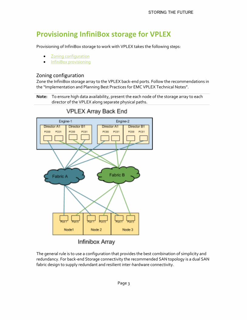
Zoning configuration Zone the InfiniBox storage array to the VPLEX back-end ports. Follow the recommendations in the “Implementation and Planning Best Practices for EMC VPLEX Technical Notes”.
Note: To ensure high data availability, present the each node of the storage array to each director of the VPLEX along separate physical paths.
The general rule is to use a configuration that provides the best combination of simplicity and redundancy. For back-end Storage connectivity the recommended SAN topology is a dual SAN fabric design to supply redundant and resilient inter-hardware connectivity.
STORING THE FUTURE
Page 4
Each director in a VPLEX cluster must have a minimum of two paths to every local back-end storage array and to every storage volume presented to VPLEX.
InfiniBox contains three or more independent interconnected nodes. Each node should have a minimum of two ports connected to the VPLEX back-end ports via physically separate SAN fabrics.
When configuring mirroring or migration across arrays, it is suggested that each array be accessed through different back-end director ports
A maximum of 4 active paths per director to a given LUN is recommended. This is considered optimal because each director will load balance across the four active paths to the storage volume.
ZONING RECOMMENDATIONS
Physical connectivity
Each VPLEX Director is connected to two FC Switches (Fabric A and Fabric B)
Each InfiniBox Node is connected to two FC Switched (Fabric A and Fabric B)
Even Numbered (0,2) VPLEX Director ports are connected to Fabric A
Odd Numbered (1,3) VPLEX Director ports are connected to Fabric B
InfiniBox Fabric A ports use HBA-1 (Ports 1-4)
InfiniBox Fabric B ports use HBA-2 (Ports 5-8)
Logical zoning
Zone VPLEX director A-00 ports to Port 1 of InfiniBox Node 1 and Node 2
Zone VPLEX director B ports to one group of Port 5 on each InfiniBox Nodes.
Repeat for additional VPLEX engines.
Create a separate host-initiator for each VPLEX cluster.
Map Volumes to allow access to the appropriate VPLEX initiators for each port groups.
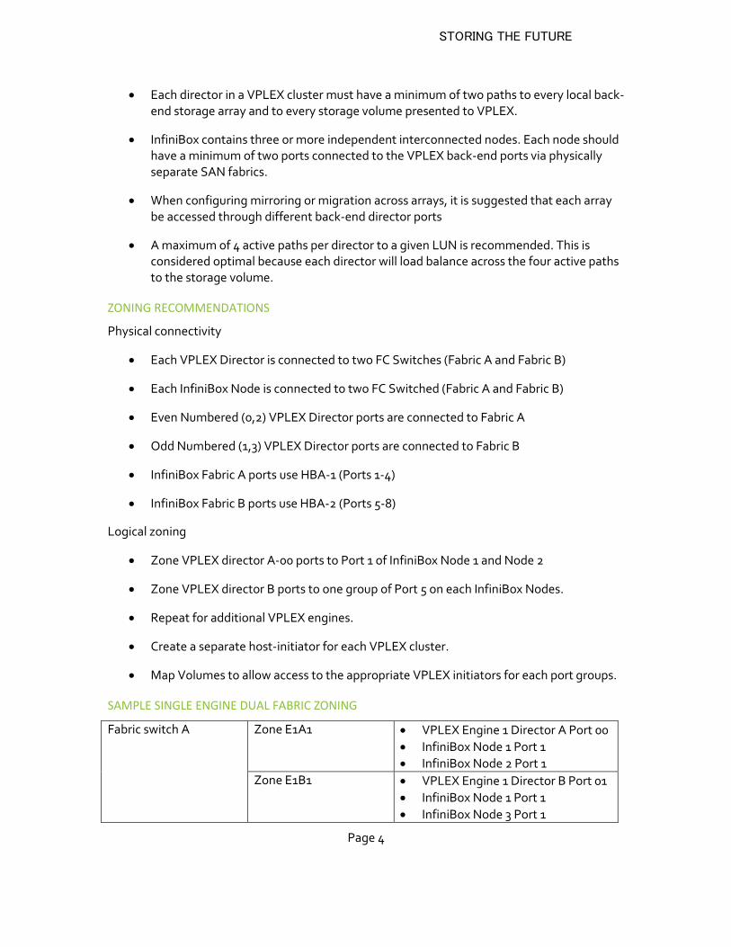
SAMPLE SINGLE ENGINE DUAL FABRIC ZONING
Fabric switch A Zone E1A1 VPLEX Engine 1 Director A Port 00
InfiniBox Node 1 Port 1
InfiniBox Node 2 Port 1
Zone E1B1 VPLEX Engine 1 Director B Port 01
InfiniBox Node 1 Port 1
InfiniBox Node 3 Port 1
STORING THE FUTURE
Page 5
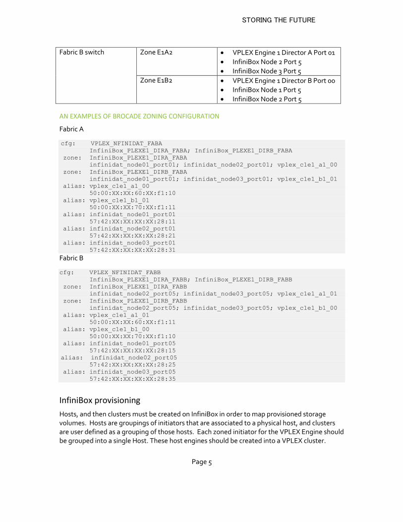
Fabric B switch Zone E1A2 VPLEX Engine 1 Director A Port 01
InfiniBox Node 2 Port 5
InfiniBox Node 3 Port 5
Zone E1B2 VPLEX Engine 1 Director B Port 00
InfiniBox Node 1 Port 5
InfiniBox Node 2 Port 5
AN EXAMPLES OF BROCADE ZONING CONFIGURATION
Fabric A
cfg: VPLEX_NFINIDAT_FABA InfiniBox_PLEXE1_DIRA_FABA; InfiniBox_PLEXE1_DIRB_FABA
zone: InfiniBox_PLEXE1_DIRA_FABA
infinidat_node01_port01; infinidat_node02_port01; vplex_c1e1_a1_00
zone: InfiniBox_PLEXE1_DIRB_FABA
infinidat_node01_port01; infinidat_node03_port01; vplex_c1e1_b1_01
alias: vplex_c1e1_a1_00
50:00:XX:XX:60:XX:f1:10
alias: vplex_c1e1_b1_01
50:00:XX:XX:70:XX:f1:11
alias: infinidat_node01_port01
57:42:XX:XX:XX:XX:28:11
alias: infinidat_node02_port01
57:42:XX:XX:XX:XX:28:21
alias: infinidat_node03_port01
57:42:XX:XX:XX:XX:28:31
Fabric B
cfg: VPLEX_NFINIDAT_FABB
InfiniBox_PLEXE1_DIRA_FABB; InfiniBox_PLEXE1_DIRB_FABB
zone: InfiniBox_PLEXE1_DIRA_FABB
infinidat_node02_port05; infinidat_node03_port05; vplex_c1e1_a1_01
zone: InfiniBox_PLEXE1_DIRB_FABB
infinidat_node02_port05; infinidat_node03_port05; vplex_c1e1_b1_00
alias: vplex_c1e1_a1_01
50:00:XX:XX:60:XX:f1:11
alias: vplex_c1e1_b1_00
50:00:XX:XX:70:XX:f1:10
alias: infinidat_node01_port05
57:42:XX:XX:XX:XX:28:15
alias: infinidat_node02_port05 57:42:XX:XX:XX:XX:28:25
alias: infinidat_node03_port05
57:42:XX:XX:XX:XX:28:35
InfiniBox provisioning
Hosts, and then clusters must be created on InfiniBox in order to map provisioned storage volumes. Hosts are groupings of initiators that are associated to a physical host, and clusters are user defined as a grouping of those hosts. Each zoned initiator for the VPLEX Engine should be grouped into a single Host. These host engines should be created into a VPLEX cluster.
STORING THE FUTURE
Page 6
Once created, storage volumes can be mapped to all grouped initiators of a given connected host. This section describes host/cluster creation, volume creation and then volume to cluster mapping.
InfiniBox provisioning takes the following steps:
Creating a host
Creating a cluster
Creating volumes
Mapping volumes to clusters
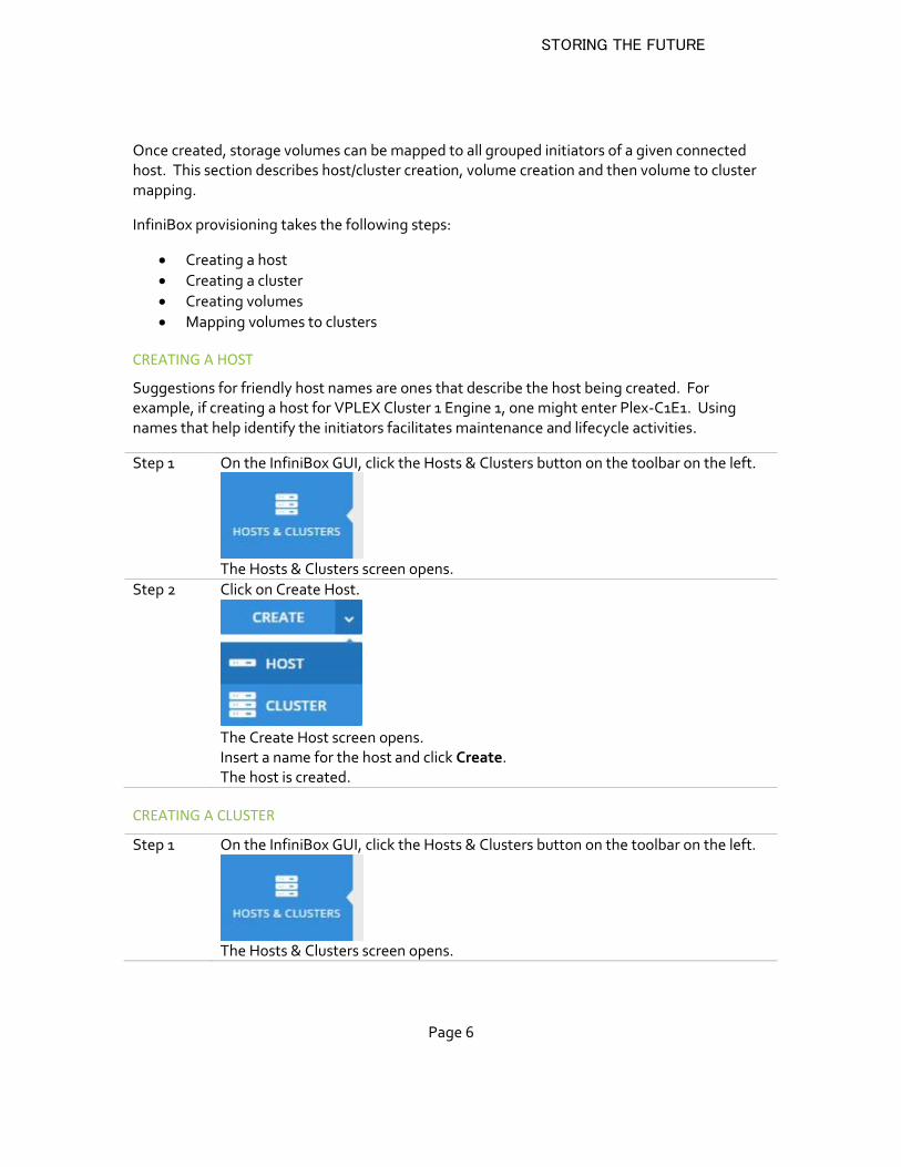
CREATING A HOST
Suggestions for friendly host names are ones that describe the host being created. For example, if creating a host for VPLEX Cluster 1 Engine 1, one might enter Plex-C1E1. Using names that help identify the initiators facilitates maintenance and lifecycle activities.
Step 1 On the InfiniBox GUI, click the Hosts & Clusters button on the toolbar on the left.
The Hosts & Clusters screen opens.
Step 2 Click on Create Host.
The Create Host screen opens. Insert a name for the host and click Create. The host is created.
CREATING A CLUSTER
Step 1 On the InfiniBox GUI, click the Hosts & Clusters button on the toolbar on the left.
The Hosts & Clusters screen opens.
STORING THE FUTURE
Page 7
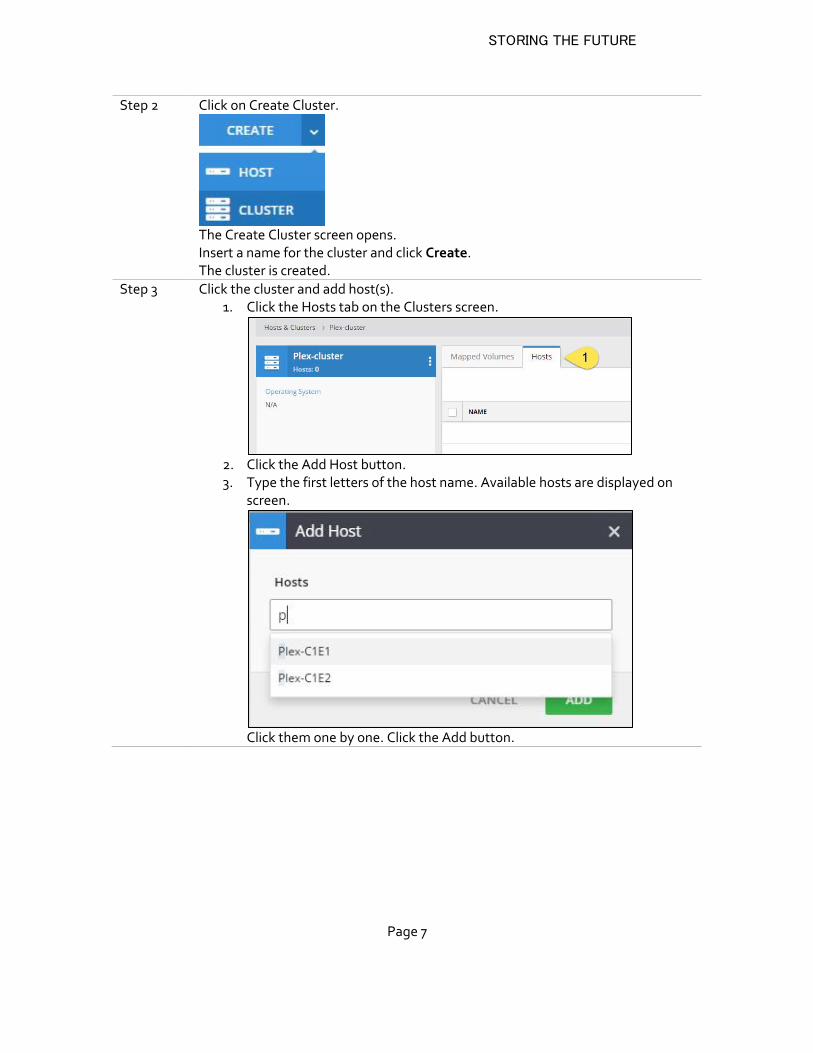
Step 2 Click on Create Cluster.
The Create Cluster screen opens. Insert a name for the cluster and click Create. The cluster is created.
Step 3 Click the cluster and add host(s). 1. Click the Hosts tab on the Clusters screen.
2. Click the Add Host button. 3. Type the first letters of the host name. Available hosts are displayed on
screen.
Click them one by one. Click the Add button.
STORING THE FUTURE
Page 8
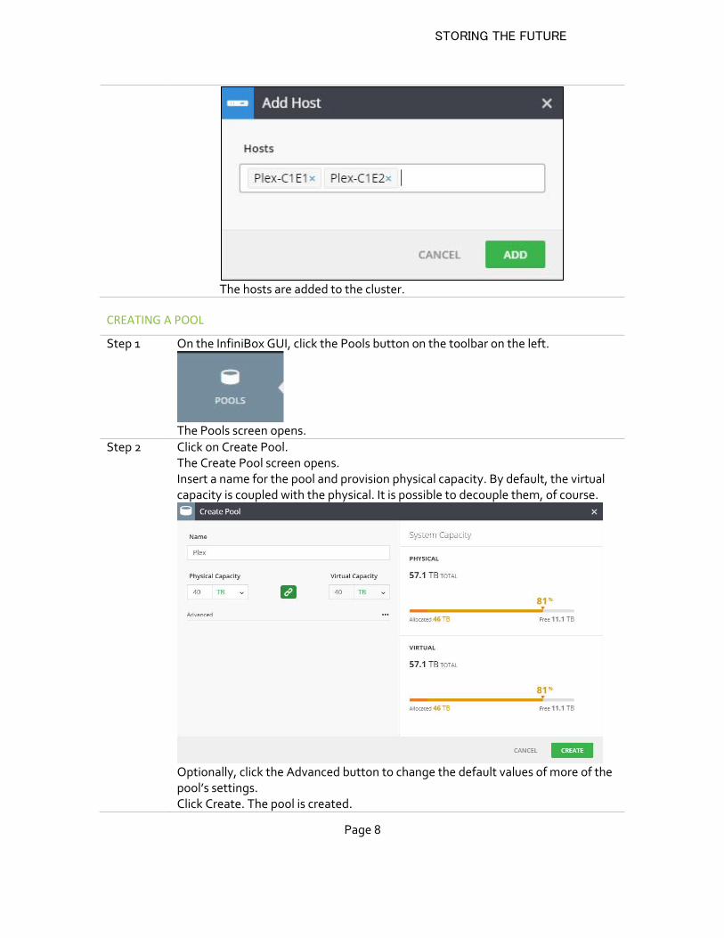
The hosts are added to the cluster.
CREATING A POOL
Step 1 On the InfiniBox GUI, click the Pools button on the toolbar on the left.
The Pools screen opens.
Step 2 Click on Create Pool. The Create Pool screen opens. Insert a name for the pool and provision physical capacity. By default, the virtual capacity is coupled with the physical. It is possible to decouple them, of course.
Optionally, click the Advanced button to change the default values of more of the pool’s settings. Click Create. The pool is created.
STORING THE FUTURE
Page 9
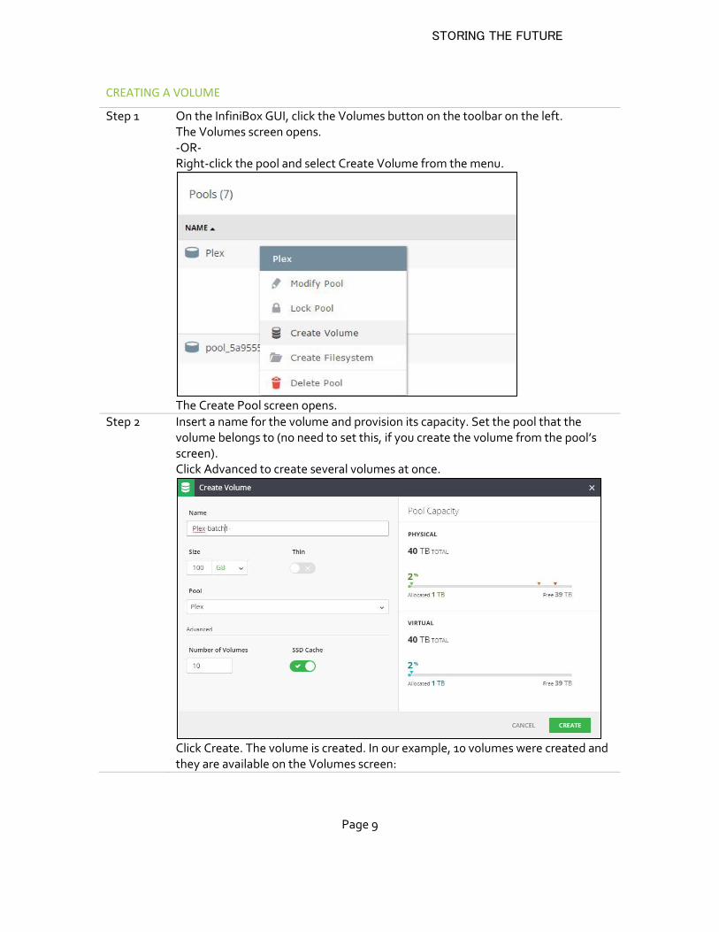
CREATING A VOLUME
Step 1 On the InfiniBox GUI, click the Volumes button on the toolbar on the left. The Volumes screen opens. -OR- Right-click the pool and select Create Volume from the menu.
The Create Pool screen opens.
Step 2 Insert a name for the volume and provision its capacity. Set the pool that the volume belongs to (no need to set this, if you create the volume from the pool’s screen). Click Advanced to create several volumes at once.
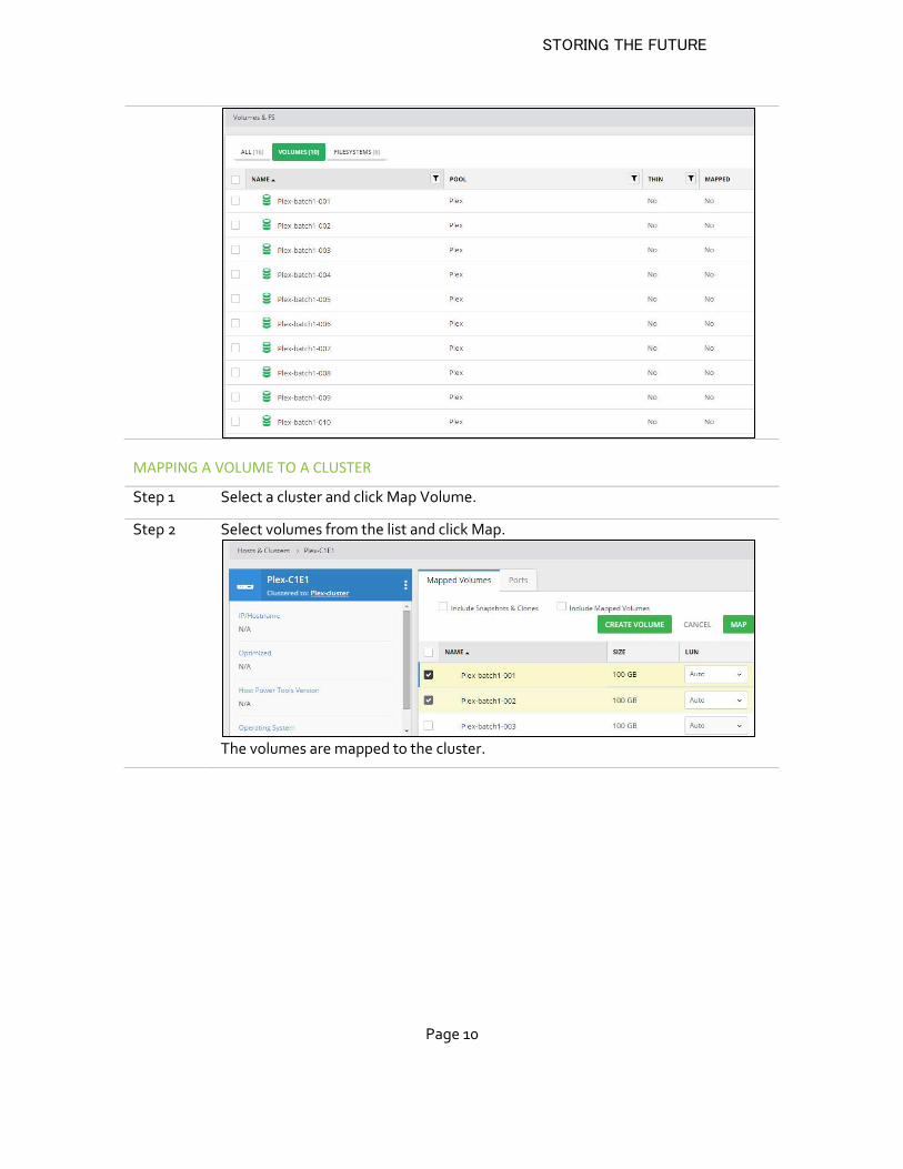
Click Create. The volume is created. In our example, 10 volumes were created and they are available on the Volumes screen:
STORING THE FUTURE
Page 10
MAPPING A VOLUME TO A CLUSTER
Step 1 Select a cluster and click Map Volume.
Step 2 Select volumes from the list and click Map.
The volumes are mapped to the cluster.
STORING THE FUTURE
Page 11
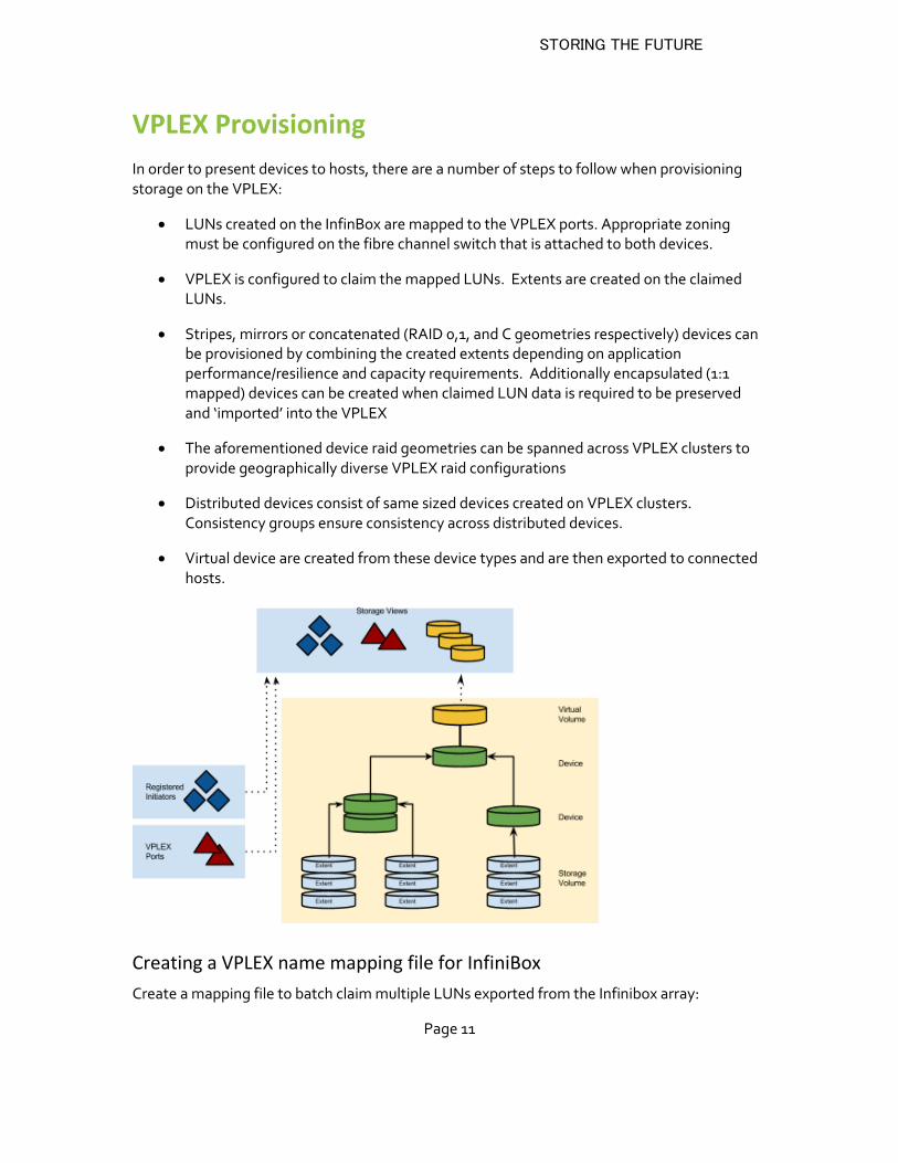
VPLEX Provisioning
In order to present devices to hosts, there are a number of steps to follow when provisioning storage on the VPLEX:
LUNs created on the InfinBox are mapped to the VPLEX ports. Appropriate zoning must be configured on the fibre channel switch that is attached to both devices.
VPLEX is configured to claim the mapped LUNs. Extents are created on the claimed LUNs.
Stripes, mirrors or concatenated (RAID 0,1, and C geometries respectively) devices can be provisioned by combining the created extents depending on application performance/resilience and capacity requirements. Additionally encapsulated (1:1 mapped) devices can be created when claimed LUN data is required to be preserved and ‘imported’ into the VPLEX
The aforementioned device raid geometries can be spanned across VPLEX clusters to provide geographically diverse VPLEX raid configurations
Distributed devices consist of same sized devices created on VPLEX clusters. Consistency groups ensure consistency across distributed devices.
Virtual device are created from these device types and are then exported to connected hosts.
Creating a VPLEX name mapping file for InfiniBox
Create a mapping file to batch claim multiple LUNs exported from the Infinibox array:
STORING THE FUTURE
Page 12
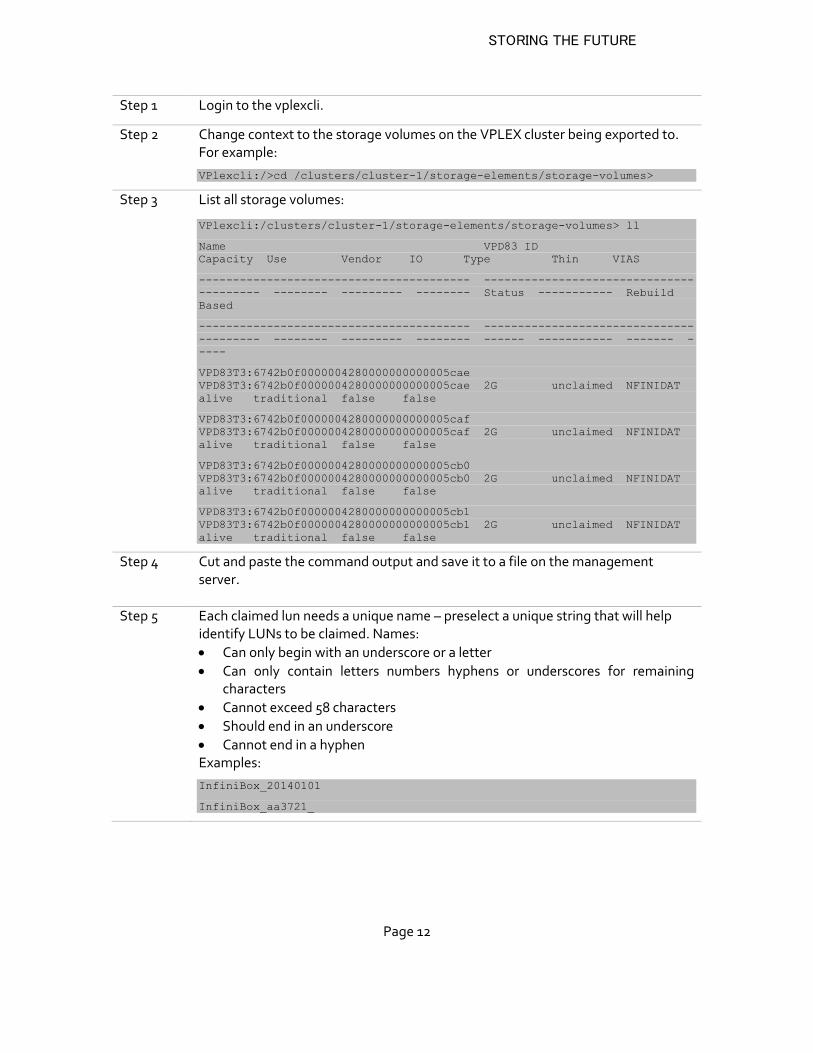
Step 1 Login to the vplexcli.
Step 2 Change context to the storage volumes on the VPLEX cluster being exported to. For example:
VPlexcli:/>cd /clusters/cluster-1/storage-elements/storage-volumes>
Step 3 List all storage volumes:
VPlexcli:/clusters/cluster-1/storage-elements/storage-volumes> ll
Name VPD83 ID
Capacity Use Vendor IO Type Thin VIAS
---------------------------------------- -------------------------------
--------- -------- --------- -------- Status ----------- Rebuild
Based
---------------------------------------- -------------------------------
--------- -------- --------- -------- ------ ----------- ------- -
----
VPD83T3:6742b0f0000004280000000000005cae
VPD83T3:6742b0f0000004280000000000005cae 2G unclaimed NFINIDAT
alive traditional false false
VPD83T3:6742b0f0000004280000000000005caf
VPD83T3:6742b0f0000004280000000000005caf 2G unclaimed NFINIDAT
alive traditional false false
VPD83T3:6742b0f0000004280000000000005cb0
VPD83T3:6742b0f0000004280000000000005cb0 2G unclaimed NFINIDAT
alive traditional false false
VPD83T3:6742b0f0000004280000000000005cb1
VPD83T3:6742b0f0000004280000000000005cb1 2G unclaimed NFINIDAT
alive traditional false false
Step 4 Cut and paste the command output and save it to a file on the management server.
Step 5 Each claimed lun needs a unique name – preselect a unique string that will help identify LUNs to be claimed. Names:
Can only begin with an underscore or a letter
Can only contain letters numbers hyphens or underscores for remaining characters
Cannot exceed 58 characters
Should end in an underscore
Cannot end in a hyphen Examples:
InfiniBox_20140101
InfiniBox_aa3721_
STORING THE FUTURE
Page 13
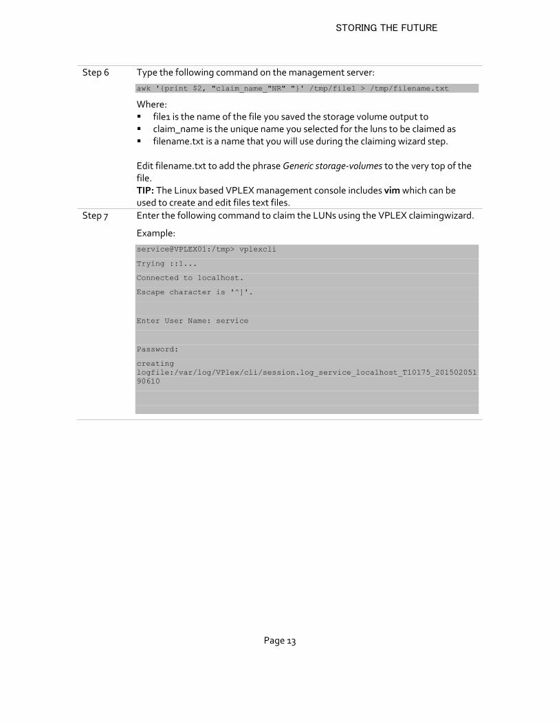
Step 6 Type the following command on the management server:
awk '{print $2, "claim_name_"NR" "}' /tmp/file1 > /tmp/filename.txt
Where: file1 is the name of the file you saved the storage volume output to claim_name is the unique name you selected for the luns to be claimed as filename.txt is a name that you will use during the claiming wizard step.
Edit filename.txt to add the phrase Generic storage-volumes to the very top of the file. TIP: The Linux based VPLEX management console includes vim which can be used to create and edit files text files.
Step 7 Enter the following command to claim the LUNs using the VPLEX claimingwizard.
Example:
service@VPLEX01:/tmp> vplexcli
Trying ::1...
Connected to localhost.
Escape character is '^]'.
Enter User Name: service
Password:
creating
logfile:/var/log/VPlex/cli/session.log_service_localhost_T10175_201502051
90610
STORING THE FUTURE
Page 14
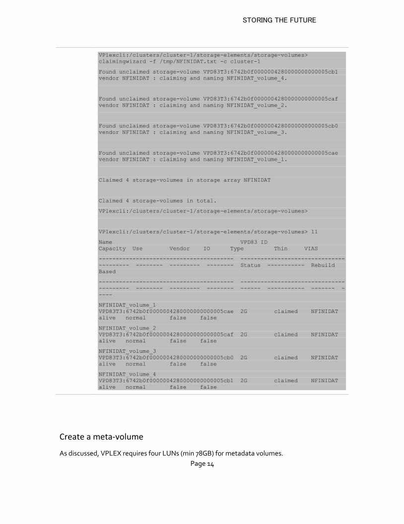
VPlexcli:/clusters/cluster-1/storage-elements/storage-volumes>
claimingwizard -f /tmp/NFINIDAT.txt -c cluster-1
Found unclaimed storage-volume VPD83T3:6742b0f0000004280000000000005cb1
vendor NFINIDAT : claiming and naming NFINIDAT_volume_4.
Found unclaimed storage-volume VPD83T3:6742b0f0000004280000000000005caf
vendor NFINIDAT : claiming and naming NFINIDAT_volume_2.
Found unclaimed storage-volume VPD83T3:6742b0f0000004280000000000005cb0
vendor NFINIDAT : claiming and naming NFINIDAT_volume_3.
Found unclaimed storage-volume VPD83T3:6742b0f0000004280000000000005cae
vendor NFINIDAT : claiming and naming NFINIDAT_volume_1.
Claimed 4 storage-volumes in storage array NFINIDAT
Claimed 4 storage-volumes in total.
VPlexcli:/clusters/cluster-1/storage-elements/storage-volumes>
VPlexcli:/clusters/cluster-1/storage-elements/storage-volumes> ll
Name VPD83 ID
Capacity Use Vendor IO Type Thin VIAS
---------------------------------------- -------------------------------
--------- -------- --------- -------- Status ----------- Rebuild
Based
---------------------------------------- -------------------------------
--------- -------- --------- -------- ------ ----------- ------- -
----
NFINIDAT_volume_1
VPD83T3:6742b0f0000004280000000000005cae 2G claimed NFINIDAT
alive normal false false
NFINIDAT_volume_2
VPD83T3:6742b0f0000004280000000000005caf 2G claimed NFINIDAT
alive normal false false
NFINIDAT_volume_3
VPD83T3:6742b0f0000004280000000000005cb0 2G claimed NFINIDAT
alive normal false false
NFINIDAT_volume_4
VPD83T3:6742b0f0000004280000000000005cb1 2G claimed NFINIDAT
alive normal false false
Create a meta-volume
As discussed, VPLEX requires four LUNs (min 78GB) for metadata volumes.
STORING THE FUTURE
Page 15
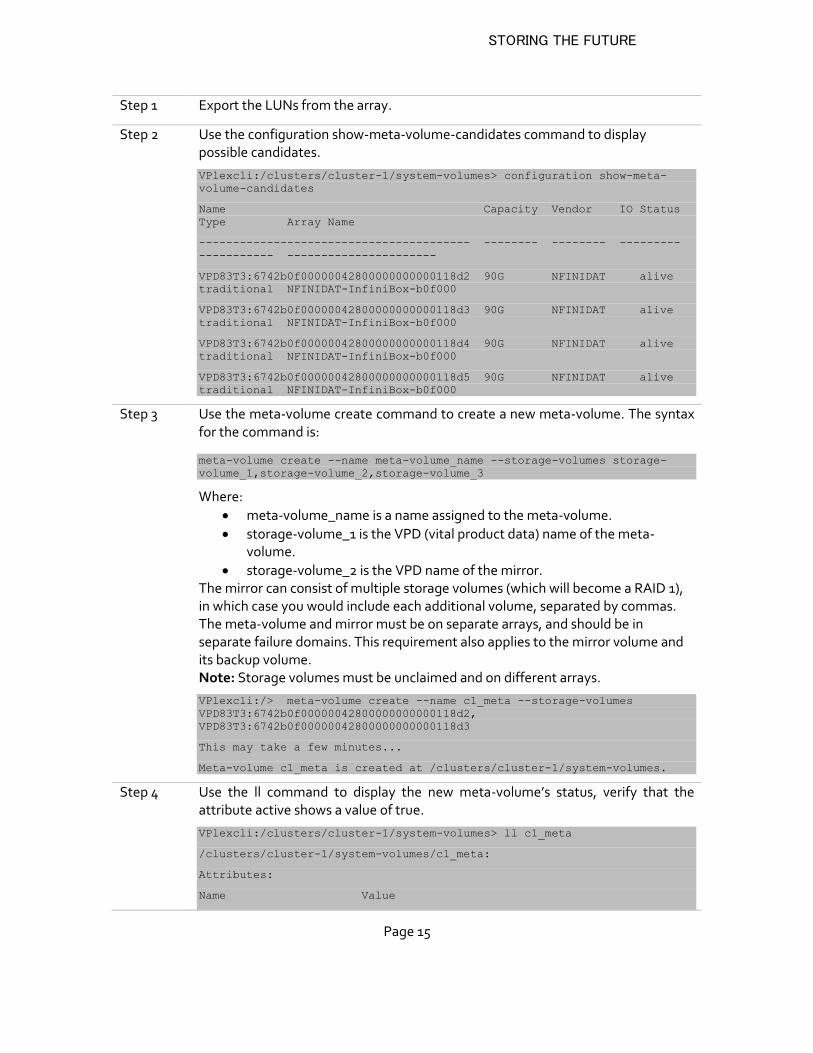
Step 1 Export the LUNs from the array.
Step 2 Use the configuration show-meta-volume-candidates command to display possible candidates.
VPlexcli:/clusters/cluster-1/system-volumes> configuration show-meta-
volume-candidates
Name Capacity Vendor IO Status
Type Array Name
---------------------------------------- -------- -------- ---------
----------- ----------------------
VPD83T3:6742b0f00000042800000000000118d2 90G NFINIDAT alive
traditional NFINIDAT-InfiniBox-b0f000
VPD83T3:6742b0f00000042800000000000118d3 90G NFINIDAT alive
traditional NFINIDAT-InfiniBox-b0f000
VPD83T3:6742b0f00000042800000000000118d4 90G NFINIDAT alive
traditional NFINIDAT-InfiniBox-b0f000
VPD83T3:6742b0f00000042800000000000118d5 90G NFINIDAT alive
traditional NFINIDAT-InfiniBox-b0f000
Step 3 Use the meta-volume create command to create a new meta-volume. The syntax for the command is:
meta-volume create --name meta-volume_name --storage-volumes storage-
volume_1,storage-volume_2,storage-volume_3
Where:
meta-volume_name is a name assigned to the meta-volume.
storage-volume_1 is the VPD (vital product data) name of the meta-volume.
storage-volume_2 is the VPD name of the mirror. The mirror can consist of multiple storage volumes (which will become a RAID 1), in which case you would include each additional volume, separated by commas. The meta-volume and mirror must be on separate arrays, and should be in separate failure domains. This requirement also applies to the mirror volume and its backup volume. Note: Storage volumes must be unclaimed and on different arrays.
VPlexcli:/> meta-volume create --name c1_meta --storage-volumes
VPD83T3:6742b0f00000042800000000000118d2,
VPD83T3:6742b0f00000042800000000000118d3
This may take a few minutes...
Meta-volume c1_meta is created at /clusters/cluster-1/system-volumes.
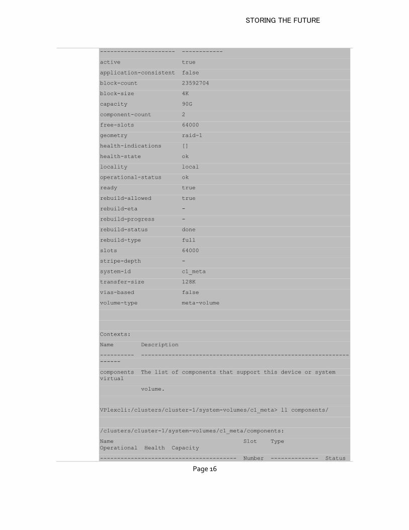
Step 4 Use the ll command to display the new meta-volume’s status, verify that the attribute active shows a value of true.
VPlexcli:/clusters/cluster-1/system-volumes> ll c1_meta
/clusters/cluster-1/system-volumes/c1_meta:
Attributes:
Name Value
STORING THE FUTURE
Page 16
---------------------- ------------
active true
application-consistent false
block-count 23592704
block-size 4K
capacity 90G
component-count 2
free-slots 64000
geometry raid-1
health-indications []
health-state ok
locality local
operational-status ok
ready true
rebuild-allowed true
rebuild-eta -
rebuild-progress -
rebuild-status done
rebuild-type full
slots 64000
stripe-depth -
system-id c1_meta
transfer-size 128K
vias-based false
volume-type meta-volume
Contexts:
Name Description
---------- -------------------------------------------------------------
------
components The list of components that support this device or system
virtual
volume.
VPlexcli:/clusters/cluster-1/system-volumes/c1_meta> ll components/
/clusters/cluster-1/system-volumes/c1_meta/components:
Name Slot Type
Operational Health Capacity
---------------------------------------- Number -------------- Status
STORING THE FUTURE
Page 17
State --------
---------------------------------------- ------ -------------- -------
---- ------ --------
VPD83T3:6742b0f00000042800000000000118d2 0 storage-volume ok
ok 90G
VPD83T3:6742b0f00000042800000000000118d3 1 storage-volume ok
ok 90G
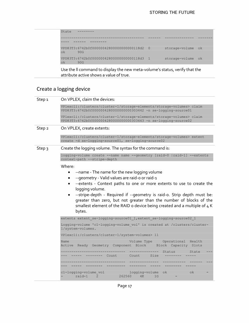
Use the ll command to display the new meta-volume’s status, verify that the attribute active shows a value of true.
Create a logging device
Step 1 On VPLEX, claim the devices:
VPlexcli:/clusters/cluster-1/storage-elements/storage-volumes> claim
VPD83T3:6742b0f0000004280000000000303442 -n se-logging-source01
VPlexcli:/clusters/cluster-1/storage-elements/storage-volumes> claim
VPD83T3:6742b0f0000004280000000000303443 -n se-logging-source02
Step 2 On VPLEX, create extents:
VPlexcli:/clusters/cluster-1/storage-elements/storage-volumes> extent
create -d se-logging-source01, se-logging-source02
Step 3 Create the logging volume. The syntax for the command is:
logging-volume create --name name --geometry [raid-0 |raid-1] --extents
context-path --stripe-depth
Where:
--name - The name for the new logging volume
--geometry - Valid values are raid-0 or raid-1
--extents - Context paths to one or more extents to use to create the logging volume.
--stripe-depth - Required if --geometry is raid-0. Strip depth must be: greater than zero, but not greater than the number of blocks of the smallest element of the RAID 0 device being created and a multiple of 4 K bytes.
extents extent_se-logging-source01_1,extent_se-logging-source02_1
Logging-volume 'c1-logging-volume_vol' is created at /clusters/cluster-
1/system-volumes.
VPlexcli:/clusters/cluster-1/system-volumes> ll
Name Volume Type Operational Health
Active Ready Geometry Component Block Block Capacity Slots
------------------------------- -------------- Status State ---
--- ----- -------- Count Count Size -------- -----
------------------------------- -------------- ----------- ------ ---
--- ----- -------- --------- -------- ----- -------- -----
c1-logging-volume_vol logging-volume ok ok -
- raid-1 2 262560 4K 1G -
STORING THE FUTURE
Page 18
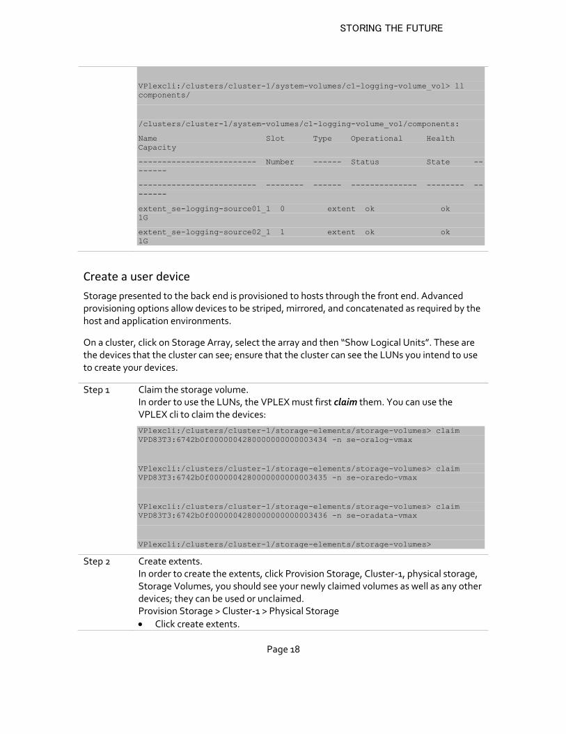
VPlexcli:/clusters/cluster-1/system-volumes/c1-logging-volume_vol> ll
components/
/clusters/cluster-1/system-volumes/c1-logging-volume_vol/components:
Name Slot Type Operational Health
Capacity
------------------------- Number ------ Status State --
------
------------------------- -------- ------ -------------- -------- --
------
extent_se-logging-source01_1 0 extent ok ok
1G
extent_se-logging-source02_1 1 extent ok ok
1G
Create a user device
Storage presented to the back end is provisioned to hosts through the front end. Advanced provisioning options allow devices to be striped, mirrored, and concatenated as required by the host and application environments.
On a cluster, click on Storage Array, select the array and then “Show Logical Units”. These are the devices that the cluster can see; ensure that the cluster can see the LUNs you intend to use to create your devices.
Step 1 Claim the storage volume. In order to use the LUNs, the VPLEX must first claim them. You can use the VPLEX cli to claim the devices:
VPlexcli:/clusters/cluster-1/storage-elements/storage-volumes> claim
VPD83T3:6742b0f0000004280000000000003434 -n se-oralog-vmax
VPlexcli:/clusters/cluster-1/storage-elements/storage-volumes> claim
VPD83T3:6742b0f0000004280000000000003435 -n se-oraredo-vmax
VPlexcli:/clusters/cluster-1/storage-elements/storage-volumes> claim
VPD83T3:6742b0f0000004280000000000003436 -n se-oradata-vmax
VPlexcli:/clusters/cluster-1/storage-elements/storage-volumes>
Step 2 Create extents. In order to create the extents, click Provision Storage, Cluster-1, physical storage, Storage Volumes, you should see your newly claimed volumes as well as any other devices; they can be used or unclaimed. Provision Storage > Cluster-1 > Physical Storage
Click create extents.
STORING THE FUTURE
Page 19
Select the devices and click “Add”
Next
Commit The VPLEX will automatically populate the left side with any possible candidates; choose the LUNs you want and add them to the right side. Click Next and then Finish.
Step 3 Create Devices from extents. From the extents, devices can be created, either using a 1:1 mapping of extent to device, or multiple extents per device. Provision Storage > Cluster-1 >Devices
Click Create
Select the devices
Devices can be created in different configurations: RAID-0, RAID-1, RAID-C
and 1:1 mapping of extents to devices.
Automatically create a virtual volume on each device: “NO”
o DO NOT create a virtual volume at this time. You will not be able to
create a distributed device if the virtual volume already exists on the
device.
Click next and then commit your changes.
Step 4 Create Virtual Volumes In order to create a virtual volume click Provision Storage, Cluster-1, Virtualized Storage and Virtual Volumes: Provision Storage > Cluster-1 >Virtual Volumes
Click “Create from Devices”
Select devices
add virtual volumes
ok
Step 5 Create Storage View
Add Initiators (Hosts, HBAs)
Go to Provision Storage and select cluster > Initiators.
Select the unregistered initiator and click Register.
Type a meaningful name for the initiator or accept the one provided.
Select a host type and click OK
add ports (FE ports VPLEX)
Add virtual volumes
STORING THE FUTURE
Page 20
EMC VPLEX-assisted data relocation
VPLEX migrations are non-disruptive. The applications do not need to be stopped in order to migrate storage. VPLEX is fully heterogeneous. It supports both EMC and non-EMC arrays.
There are two primary use cases for data relocation:
Tech-refresh of an old array: In this use case, a new array is placed under VPLEX management. Volumes from an existing array are migrated onto the new array. Typically, the older array is then retired or repurposed.
Load balancing across arrays: In this use case, there are multiple arrays behind VPLEX. Either because of capacity reasons or performance reasons or the need for some specific capability, volumes need to be moved from one array to another. Both arrays continue to be kept in service after the volume moves are complete.
VPLEX Local can be used to accomplish both use cases above.
VPLEX Metro adds one more variant to the above scenarios:
Migrating across arrays across data centers. VPLEX Metro extends the pool of arrays that you can manage beyond the confines of your data center.
Available operations:
Extent - performs intra-cluster move of data from one extent to another.
Device - performs intra-cluster move of data from one device to another.
Batch - a CLI only option that groups extent or device mobility jobs into a batch job.
Migration procedure
1. Create a batch migration plan. A plan is a file that identifies the source and target
devices and other attributes.
2. Check the plan and then start the migration session.
3. Verify the status of the migration.
4. Verify that the migration has completed. When the migration completes the
percentage done will show 100.
5. Once the synchronization completes, the migration session can be committed.
6. Clean up the migration. This dismantles the source device down to the storage volume
and the source storage device is changed to an unclaimed state.
7. Remove all information about the migration session from the VPLEX.
8. Post-Migration task, depends if you want to redeployed the devices for other uses in
the VPLEX or if the source storage system needs to be removed by performing the
necessary masking, zoning, and other configuration changes.
STORING THE FUTURE
Page 21
Migration Steps
Initial
state
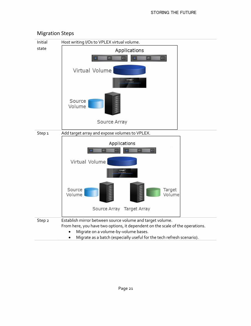
Host writing I/Os to VPLEX virtual volume.
Step 1 Add target array and expose volumes to VPLEX.
Step 2 Establish mirror between source volume and target volume.
From here, you have two options, it dependent on the scale of the operations.
Migrate on a volume-by-volume bases.
Migrate as a batch (especially useful for the tech refresh scenario).
STORING THE FUTURE
Page 22
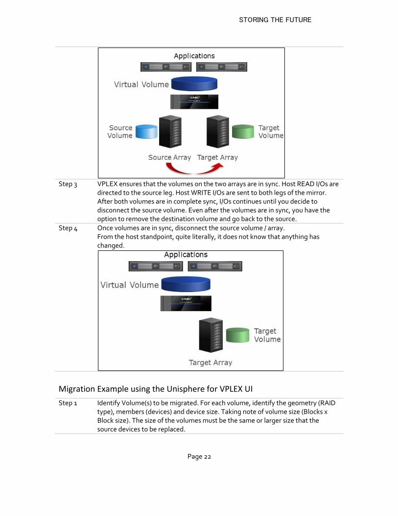
Step 3 VPLEX ensures that the volumes on the two arrays are in sync. Host READ I/Os are
directed to the source leg. Host WRITE I/Os are sent to both legs of the mirror. After both volumes are in complete sync, I/Os continues until you decide to disconnect the source volume. Even after the volumes are in sync, you have the option to remove the destination volume and go back to the source.
Step 4 Once volumes are in sync, disconnect the source volume / array. From the host standpoint, quite literally, it does not know that anything has changed.
Migration Example using the Unisphere for VPLEX UI
Step 1 Identify Volume(s) to be migrated. For each volume, identify the geometry (RAID type), members (devices) and device size. Taking note of volume size (Blocks x Block size). The size of the volumes must be the same or larger size that the source devices to be replaced.
STORING THE FUTURE
Page 23
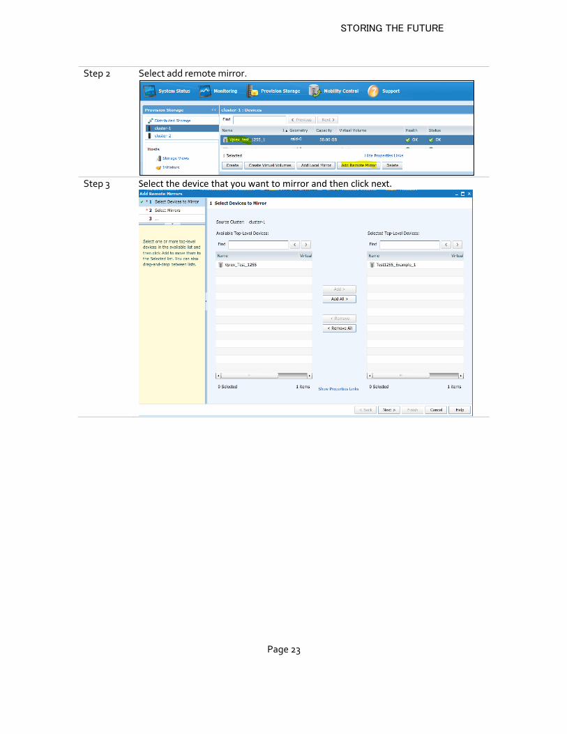
Step 2 Select add remote mirror.
Step 3 Select the device that you want to mirror and then click next.
STORING THE FUTURE
Page 24
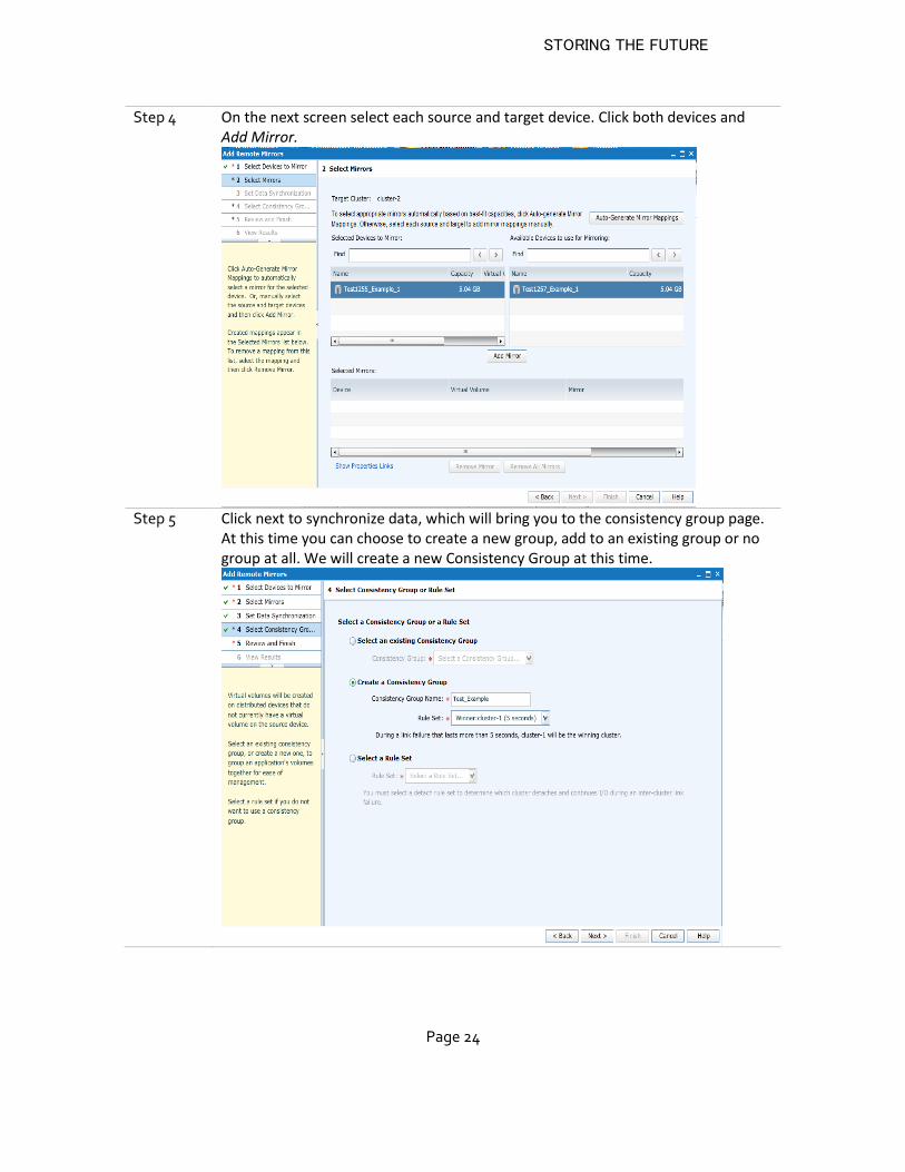
Step 4 On the next screen select each source and target device. Click both devices and Add Mirror.
Step 5 Click next to synchronize data, which will bring you to the consistency group page.
At this time you can choose to create a new group, add to an existing group or no group at all. We will create a new Consistency Group at this time.
STORING THE FUTURE
Page 25
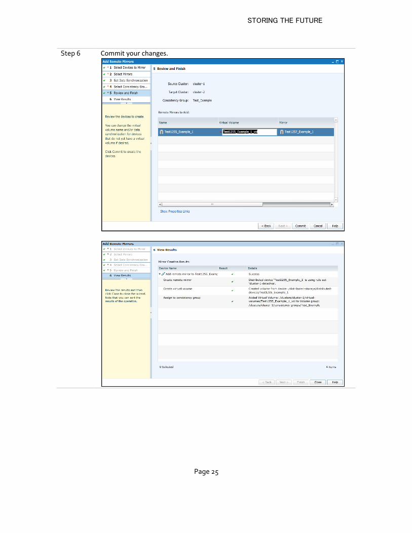
Step 6 Commit your changes.
STORING THE FUTURE
Page 26
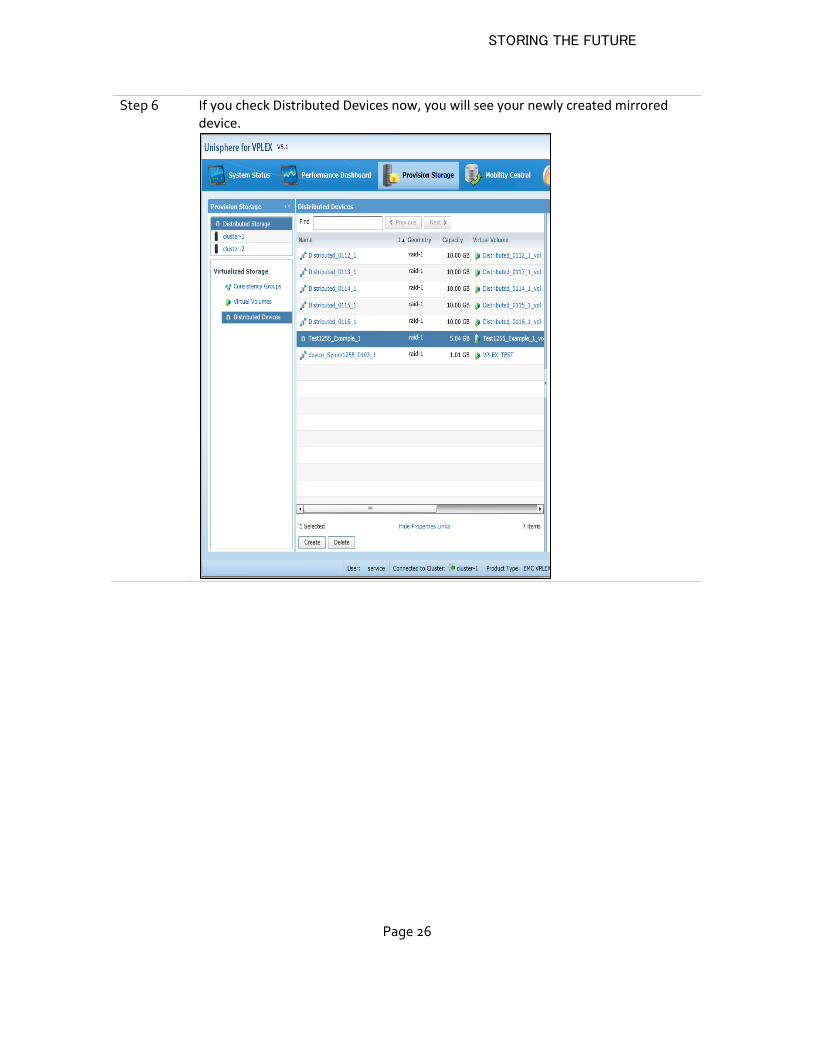
Step 6 If you check Distributed Devices now, you will see your newly created mirrored device.
STORING THE FUTURE
Page 27
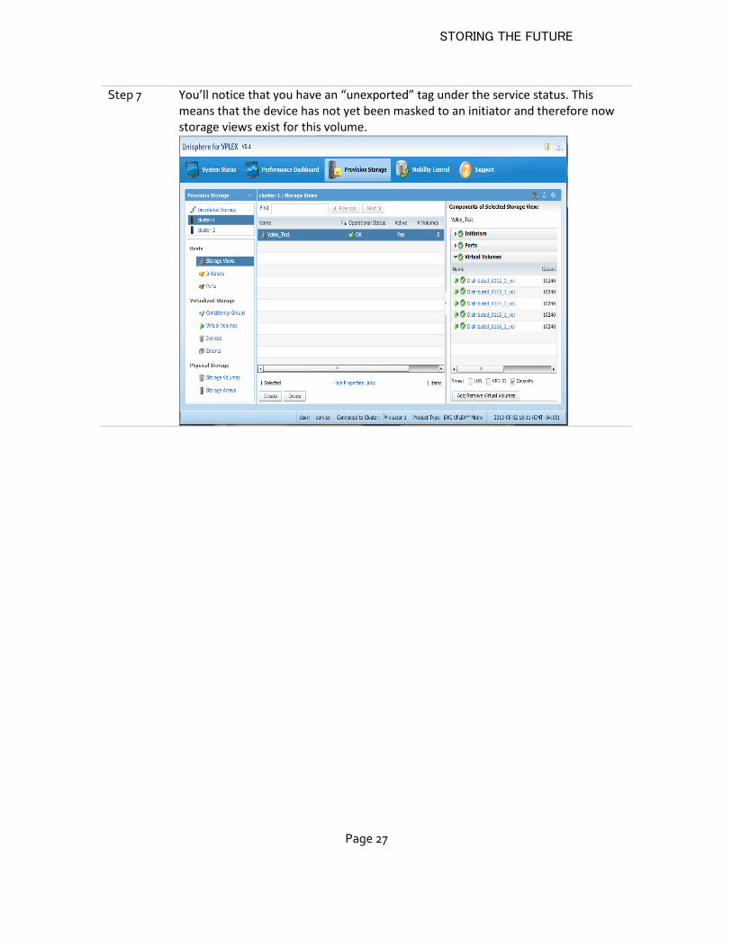
Step 7 You’ll notice that you have an “unexported” tag under the service status. This means that the device has not yet been masked to an initiator and therefore now storage views exist for this volume.
STORING THE FUTURE
Page 28
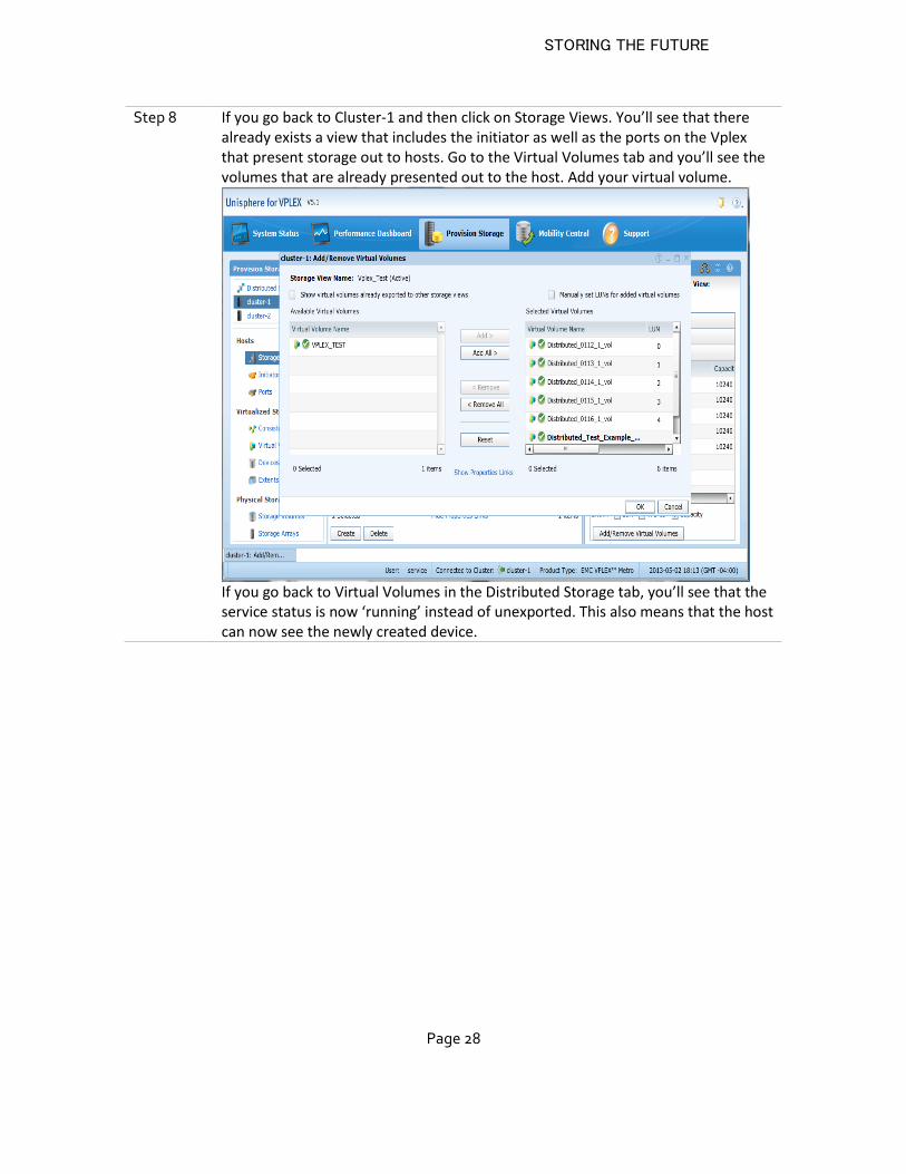
Step 8 If you go back to Cluster-1 and then click on Storage Views. You’ll see that there already exists a view that includes the initiator as well as the ports on the Vplex that present storage out to hosts. Go to the Virtual Volumes tab and you’ll see the volumes that are already presented out to the host. Add your virtual volume.
If you go back to Virtual Volumes in the Distributed Storage tab, you’ll see that the service status is now ‘running’ instead of unexported. This also means that the host can now see the newly created device.
STORING THE FUTURE
Page 29
Considerations and best practices
Schedule data migration during off-hours to minimize the impact of an increased workload on the back end
Consider pausing data migration during critical hours of production and resuming it during off-peak hours.
Up to 25 migration sessions can run concurrently on a VPLEX system. Additional sessions can be defined and queued for execution. When a running session completes, a queued session will begin.
Migrate one server or cluster at a time.
The default transfer size value is 2 MB. It is configurable for 4 KB to 32MB. When the transfer size is set large, migration will be faster but potentially could impact performance on the front end. Smaller transfer size will result in less front-end impact but migrations will take longer.
A batch can process either extents or devices, but not a mix of both.
Batch mobility can only be performed via the CLI.
Best practices recommendations when provisioning Virtual Devices
CONSIDERATIONS FOR META-VOLUMES:
For each VPLEX cluster, allocate four storage volumes of at least 80 GB as metadata volumes.
Configure the metadata volumes for each cluster with multiple back-end storage volumes provided by different storage arrays of the same type.
Use Infini-RAID for metadata volumes. The data protection capabilities provided by these storage arrays ensure the integrity of the system's metadata.
Read caching should be enabled.
A hot spare meta-volume must be preconfigured in case of a catastrophic failure of the active meta-volume.
CONSIDERATIONS FOR LOGGING DEVICES
VPLEX uses logging devices to track changes during a loss of connectivity or loss of a volume that is a mirror in a distributed device.
STORING THE FUTURE
Page 30
Use Infini-RAID for logging volumes. The data protection capabilities provided by the storage array ensure the integrity of the logging volumes.
Each VPLEX cluster should have sufficient logging volumes to support its distributed devices. The logging volume must be large enough to contain one bit for every page of distributed storage space. See EMC documentation.
For logging volumes the best practice is to mirror them across two or more back-end arrays to eliminate the possibility of data loss on these volumes.
You can have more than one logging volume, and can select which logging volume is used for which distributed device.
The logging devices can experience significant I/O bursts during and after link outages. The best practice is to stripe each logging volume across many [TG1] disk for speed and also to have a mirror on a separate back-end array.
Volumes that will be used for logging volumes must be initialized (have zeros written to their entire LBA range) before they can be used.
CONSIDERATIONS FOR USER VOLUMES
Extents should be sized to match the desired virtual volume's capacity. Do not create smaller extents and then use devices to concatenate or stripe the extents. When disk capacities are smaller than desired volume capacities, best practice is to create a single slice per disk, and use RAID structures to concatenate or stripe these slices into a larger user volume.
Each storage view contains a list of host/initiator ports, VPLEX FE ports, and virtual volumes. A one-to-one mapping of storage view and host is recommended.
Each storage view should contain a minimum of two director FE ports, one from an A director and one from a B director.
A storage view should contain a recommended minimum of two host initiator ports.
© Copyright INFINIDAT LTD 2015.
This document is current as of the date of and may be changed by INFINIDAT at any time. Not all offerings are available in every country in which INFINIDAT operates.
The data discussed herein is presented as derived under specific operating conditions. Actual results may vary. THE INFORMATION IN THIS DOCUMENT IS PROVIDED “AS IS” WITHOUT ANY WARRANTY, EXPRESSED OR IMPLIED, INCLUDING WITHOUT ANY WARRANTIES OF MERCHANTABILITY, FITNESS FOR A PARTICULAR PURPOSE AND ANY WARRANTY OR CONDITION OF NON-INFRINGEMENT. INFINIDAT products are warranted according to the terms and conditions of the agreements under which they are provided.
INFINIDAT, The INFINIDAT logo, InfiniBox, InfiniRAID, InfiniSnap, InfiniMetrics, and any other applicable product trademarks are registered trademarks or trademarks of INFINIDAT LTD in the United States and other countries. Other product and service names might be trademarks of INFINIDAT or other companies. A current list of INFINIDAT trademarks is available online at http://www.infinidat.com/legal/trademarks/
Please Recycle