
Infiltrator Quick4 Chambers Design and Installation · PDF filePonemah Collis Day Pine Center...
32
DECEMBER 2009 Design and Installation Manual for Quick4 ® Chambers in Minnesota INTRODUCTION 2 PRODUCTS 4 SYSTEM SIZING 8 CHAMBER CONFIGURATIONS 11 QUICK4 INSTALLATION 35 90 94 90 35 35 Saint Paul Minneapolis Arnold Ponemah Collis Day Pine Center Brushvale Malmo Lawndale Leader Holyoke Averill Richwood Two Inlets Alborn Lake Itasca Beaulieu Zim Pinewood Eldred Britt Embarrass Saum Tabor High Landing Margie Waskish Nett Lake Four Town Crane Lake Ray Skime Loman Indus Pencer Clementson Pinecreek Angle Inlet TRENCH SYSTEMS 15 SEEPAGE BEDS 18 AT-GRADE SYSTEMS 20 MOUND SYSTEMS 23 QUICK4 PLUS INSTALLATION TRENCH SYSTEMS 26 PRESSURE SYSTEMS 30 wq-wwists4-57c
Transcript of Infiltrator Quick4 Chambers Design and Installation · PDF filePonemah Collis Day Pine Center...

DECEMBER 2009
Design and Installation Manual forQuick4® Chambers in Minnesota
INTRODUCTION 2
PRODUCTS 4
SYSTEM SIZING 8
CHAMBERCONFIGURATIONS 11
QUICK4 INSTALLATION
35
90
94
90
35
35
Saint PaulMinneapolis
Arnold
Ponemah
CollisDay
Pine Center
Brushvale Malmo
Lawndale Leader
Holyoke
Averill RichwoodTwo Inlets
Alborn
Lake Itasca
Beaulieu Zim
Pinewood
EldredBritt
Embarrass
Saum
Tabor High LandingMargie
WaskishNett Lake
Four Town Crane Lake
Ray
SkimeLoman
IndusPencer
Clementson
Pinecreek
Angle Inlet
TRENCH SYSTEMS 15
SEEPAGE BEDS 18
AT-GRADE SYSTEMS 20
MOUND SYSTEMS 23
QUICK4 PLUS INSTALLATION
TRENCH SYSTEMS 26
PRESSURE SYSTEMS 30
wq-wwists4-57c

INTRODUCTION
The purpose of this manual is to provide minimum specifications for design and installation of Quick4® and Quick4 Pluschambers approved for use in Minnesota in conformance with the Minnesota Pollution Control Agency (MPCA), designstandards for individual subsurface sewage treatment systems. Each revised version of this design and installation manualsupersedes the previous version. Please contact us or visit our website for more information regarding the most recentversion of this design and installation manual.
For more detailed design and installation information, please contact Infiltrator Systems at 1-800-221-4436.
Page 2 Contact Infiltrator Systems, Inc. 1-800-221-4436 for additional Minnesota technical and product information.
Quick4 Equalizer® 24 LP ChambersThe Quick4 Equalizer 24 LP chamber was designed for shallowplacement applications and can be installed in an 18-inch-wideor 24-inch-wide trench. The Low Profile End Cap offers a simpleoverlap design for easy installation.
Quick4 Equalizer 24 ChambersThe Quick4 Equalizer 24 chambers can be installed in an18-inch-wide or 24-inch-wide trench. The chamber offersadvanced contouring capability with its Contour SwivelConnection™. The MultiPortTM End Cap with its six molded-in highand low inlets allows for maximum piping flexibility.
Quick4 Equalizer 36 ChambersThe patented Quick4 Equalizer 36 chamber can be installed in a24-inch-wide trench. The chamber offers advanced contouringcapability with its Contour Swivel Connection. The MultiPort EndCap with its six molded-in high and low inlets allows formaximum piping flexibility.
Quick4 Equalizer 24 Low Profile (LP) Nominal Chamber Specifications
Size (W x L x H) 16" x 48" x 8"
Effective Length 48"
Invert Elevation 2", 6”
Quick4 Equalizer 24 Nominal Chamber Specifications
Size (W x L x H) 16" x 48" x 12"
Effective Length 48"
Invert Elevation 6"
Quick4 Equalizer 36 Nominal Chamber Specifications
Size (W x L x H) 22" x 48" x 12"
Effective Length 48"
Invert Elevation 6"
QUICK4 EQUALIZER 24LOW PROFILE CHAMBER
LOW PROFILE END CAP
QUICK4 EQUALIZER 24CHAMBER
MULTIPORT END CAP
QUICK4 EQUALIZER 36CHAMBER
MULTIPORT END CAP

Contact Infiltrator Systems, Inc. 1-800-221-4436 for additional Minnesota technical and product information. Page 3
Quick4 Standard ChambersThe Quick4 Standard chamber can be installed in a 36-inch-widetrench and offers advanced contouring capability with its ContourSwivel Connection. The MultiPort End Cap has eight molded-in high andlow inlets allowing for maximum piping flexibility. There are a varietyof system inletting options to choose from.
MULTIPORT END CAP
Quick4 Plus Standard ChambersThe Quick4 Plus Standard chamber can be installed in a 36-inch-widetrench. This chamber offers superior strength through its centerstructural column. The Quick4 Plus All-in-One and the Quick4 PlusEndcaps are available with this chamber, providing increased flexibilityin system configurations.
QUICK4 PLUS STANDARD LP CHAMBER
INTRODUCTION
Quick4 PlusTM Standard LP ChambersThe Quick4 Plus Standard Low Profile (LP) chamber can be installed ina 36-inch-wide trench. This chamber is 4 inches shorter than otherstandard model chambers allowing for shallower installation. TheQuick4 Plus All-in-One and the Quick4 Plus Endcaps are available withthis chamber, providing increased flexibility in system configurations.
Quick4 Plus Standard Low Profile (LP) Nominal Chamber Specifications
Size (W x L x H) 34" x 48" x 8"
Effective Length 48"
Invert Elevation 0.6”, 3.3”, 7.3”, 9.0”
Quick4 Plus Standard Nominal Chamber Specifications
Size (W x L x H) 34" x 48" x 12"
Effective Length 48"
Invert Elevation 8 ”
Quick4 Plus Standard Nominal Chamber Specifications
Size (W x L x H) 34" x 48" x 12"
Effective Length 48"
Invert Elevation 0.6”, 3.3”, 7.3”, 9.0”
Quick4 High Capacity ChambersThe Quick4 High Capacity chamber can be installed in a 36-inch-widetrench. The MultiPort End Cap has eight molded-in high and low inletsto allow piping to enter or exit from multiple directions.
Quick4 Plus High Capacity Nominal Chamber Specifications
Size (W x L x H) 34" x 48" x 16"
Effective Length 48"
Invert Elevation 11.5”
QUICK4 PLUS ENDCAP
QUICK4 PLUS STANDARD CHAMBER
QUICK4 ALL-IN-ONE ENDCAP
QUICK4 STANDARD CHAMBER
QUICK4 HIGH CAPACITY CHAMBER

PRODUCTS
Quick4 Equalizer 24 Low Profile (LP) Chambers
Quick4 Equalizer 24 Chambers
48"EFFECTIVE LENGTH
6" AVG.
SIDE AND END VIEWS(not to scale)
14” ID
FRONT VIEW SIDE VIEW
LOW PROFILE END CAP(Not to scale)
SIDE AND END VIEWS(not to scale)
16"
11"
14" ID
(EFFECTIVE LENGTH)48"
9" AVG.
FRONT VIEW
MULTIPORT END CAP(Not to scale)
16" 6"
11"
0.76'OUTLET*
1.12' INLET*
14"
SIDE VIEW
* Installed lengths
Page 4 Contact Infiltrator Systems, Inc. 1-800-221-4436 for additional Minnesota technical and product information.

PRODUCTS
Contact Infiltrator Systems, Inc. 1-800-221-4436 for additional Minnesota technical and product information. Page 5
Quick4 Equalizer 36 Chambers
22"
12"
19" ID(EFFECTIVE LENGTH)48"
10" AVG.
22"
6"
12"
16"
FRONT VIEW SIDE VIEW
12"
34"
29" ID
(EFFECTIVE LENGTH)48"
7" AVG.
34"
8"
12"
16"
MULTIPORT END CAP
(Not to scale)
Front Side
SIDE AND END VIEWS
(Not to scale)
MULTIPORT END CAP(Not to scale)
SIDE AND END VIEWS(Not to scale)
Quick4 Standard Chambers

PRODUCTS
48"EFFECTIVE LENGTH
8" AVG.
SIDE AND END VIEWS
(Not to scale)
Inlet
34"
12"
30" ID
Quick4 Plus Standard Low Profile (LP) Chambers
48"EFFECTIVE LENGTH
6" AVG.
SIDE AND END VIEWS
(Not to scale)
Inlet
34"
8"
30" ID
Quick4 Plus All-in-One End Cap
17.8"
SIDE AND END VIEWS
(Not to scale)
Quick4 Plus End Cap
17.8"
SIDE AND END VIEWS
(Not to scale)
Quick4 Plus Standard Chambers
Front Side
10.4"
4.5"
Front Side
Page 6 Contact Infiltrator Systems, Inc. 1-800-221-4436 for additional Minnesota technical and product information.

PRODUCTS
SIDE AND END VIEWS
(Not to scale)
MULTIPORT END CAP(Not to scale)
16"
34"29" ID
(EFFECTIVE LENGTH)48"
12" AVG.
34"
16"
11.5"
19"
0.98'OUTLET*
1.43' INLET*
FRONT VIEW SIDE VIEW
Quick4 Invert Adapter
Quick4 High Capacity Chambers
SIDE AND END VIEWS
(Not to scale)
Front Side
4"9"
7
6.3
QUICK4 INVERT A
QUICK4 PLUS ALL-IN-ONE ENDCAP
Contact Infiltrator Systems, Inc. 1-800-221-4436 for additional Minnesota technical and product information. Page 7

SYSTEM SIZING
Chamber Ratings
TABLE 1: TRENCH SIZING FOR CLASSIFICATION I DWELLINGS1 AND EFFLUENT TREATMENT LEVEL CQUICK4 STANDARD, QUICK4 PLUS STANDARD, AND QUICK4 PLUS STANDARD LOW PROFILE (LP) CHAMBERSSIZING CREDIT PER CHAMBER = 12 SF OR 3 SF/LF
Soil LoadingRate
(gpd/sf)2
Number of Bedrooms2 3 4 5
Number ofChambers Linear Feet Number of
Chambers Linear Feet Number ofChambers Linear Feet Number of
Chambers Linear Feet
1.20 21 84 32 128 42 168 52 208
0.78 32 128 48 192 65 260 81 324
0.60 42 168 63 252 84 336 105 420
0.50 50 200 75 300 100 400 125 500
0.45 56 224 84 336 112 448 139 556
0.24 105 420 157 628 209 836 261 1044
Notes:1. Sizing for Classification II and III dwellings shall use design flows in Table IV of Section 7080.1850.2. Soil loading rates and corresponding soil texture groups are based on Table IX and IXa of Section 7080.2150.3. Rapidly permeable soil textures require conformance with Section 7080.2260, including, but not limited to pressure distribution of effluent.
TABLE 2: TRENCH SIZING FOR CLASSIFICATION I DWELLINGS1 AND EFFLUENT TREATMENT LEVEL CQUICK4 HIGH CAPACITY CHAMBER AT A 20% BOTTOM REDUCTION2
SIZING CREDIT PER CHAMBER = 15 SF OR 3.75 SF/LF
Soil LoadingRate
(gpd/sf)3
Number of Bedrooms2 3 4 5
Number ofChambers Linear Feet Number of
Chambers Linear Feet Number ofChambers Linear Feet Number of
Chambers Linear Feet
1.20 195 76 25 100 34 136 42 168
0.78 26 104 39 156 52 208 65 260
0.60 34 136 50 200 67 268 84 336
0.50 40 160 60 240 80 320 100 400
0.45 45 180 67 268 89 356 112 448
0.24 84 336 125 500 167 668 209 836
Notes:1. Sizing for Classification II and III dwellings shall use design flows in Table IV of Section 7080.1850.2. As allowed under Section 7080.2210, Subpart 3(B), a bottom area reduction of 20% has been included in the trench sizing calculation.3. Soil loading rates and corresponding soil texture groups are based on Table IX and IXa of Section 7080.2150.4. Rapidly permeable soil textures require conformance with Section 7080.2260, including, but not limited to pressure distribution of effluent.5. Minimum trench length or number of chambers required by Infiltrator.6. The drop between the drop box and end cap inlet invert must be equal to or greater than 0.5 inches.7. The 20% bottom area reduction is only applicable to Infiltrator’s High Capacity chamber models used in trenches.
For trench applications, the following shall be the basis for establishing equivalency for nominal chamber width to stone and pipetrench width.
• A 16-inch-wide chamber is equivalent to an 18-inch-wide stone and pipe trench• A 22-inch-wide chamber is equivalent to an 24-inch-wide stone and pipe trench• A 34-inch-wide chamber is equivalent to an 36-inch-wide stone and pipe trench
Note: The 34-inch-wide Quick4 High Capacity chamber is eligible for a bottom area reduction under Section 7080.2210, Subpart 3(B).
Page 8 Contact Infiltrator Systems, Inc. 1-800-221-4436 for additional Minnesota technical and product information.

TABLE 3: AT-GRADE SIZING
Infiltrator Chamber Model Number of Chambers Spanning At-GradeDistribution Media Width At-Grade Design Distribution Media Width (ft)
Quick4 Plus Standard Low Profile (LP)
1 3
2 6
3 9
4 12
5 15
Quick4 Standard
1 3
2 6
3 9
4 12
5 15
Quick4 Plus Standard
1 3
2 6
3 9
4 12
5 15
Notes:1. At-grade shall be designed by bottom area only.2. At-grade designs may be utilized when the upper 12 inches of the absorption area contains original soil with a loading rate of 0.45 gallons per dayper square foot or greater, as provided in 7080.2150, Subpart 3(E).3. At-grade systems may only be installed on slopes less than or equal to 25 percent.4. For slopes greater than one percent, the design absorption area excludes the area upslope from the top distribution line.5. The maximum allowable at-grade bed width is 15 feet.
Contact Infiltrator Systems, Inc. 1-800-221-4436 for additional Minnesota technical and product information. Page 9
SYSTEM SIZING

TABLE 6: SEEPAGE BED SIZING
Infiltrator Chamber Model Number of Chambers Spanning Width Bed Design Width (ft)
Quick4 Plus Standard Low Profile (LP)4 12
8 24
Quick4 Standard4 12
8 24
Quick4 Plus Standard4 12
8 24
Quick4 High Capacity4 12
8 24
Notes:1. When a seepage bed is specified with a design width less than or equal to 12 feet, gravity distribution may be utilized.2. Seepage bed design greater than 12 feet and up to 25 feet in width require pressure distribution.
TABLE 5: MOUND SIZING
Infiltrator Chamber Model Number of Chambers Spanning MoundDistribution Media Width Mound Design Distribution Media Width (ft)
Quick4 Plus Standard Low Profile (LP)1 32 63 9
Quick4 Standard1 32 63 9
Quick4 Plus Standard1 32 63 9
Notes:1. Mounds shall be sized by bottom area only.2. The size of the mound shall be calculated by dividing the design flow by 1.2 gallons per day per square foot.3. The maximum allowable width for mound distribution media beds is 9 feet.
TABLE 7: ABSORPTION AREA FOR QUICK4 CHAMBER END CAPS
Infiltrator Chamber Model End Cap Model Area Credit
Quick4 Equalizer 24 Low Profile (LP) MultiPort End Cap 0.87 sf/pair
Quick4 Equalizer 24 MultiPort End Cap 2.33 sf/pair
Quick4 Equalizer 36 MultiPort End Cap 3.25 sf/pair
Quick4 Plus Standard Low Profile (LP) Quick4 Plus Endcap 0.56 sf/end cap
Quick4 Plus All-in-One Endcap installedmid-line with chambers
1.29 sf/end cap
Quick4 Plus All-in-One Endcap installedat end of chamber line
1.65 sf/end cap
Quick4 Standard MultiPort End Cap 4.62 sf/pair
Quick4 Plus Standard Quick4 Plus Endcap 0.56 sf/end cap
Quick4 Plus All-in-One Endcap installedmid-line with chambers
1.29 sf/end cap
Quick4 Plus All-in-One Endcap installedmid-line with chambers
1.65 sf/end cap
Quick4 High Capacity MultiPort End Cap 6.02 sf/pair
Notes:1. End caps provide additional bottom absorption area.2. End caps may be cumulatively included as part of the total design area for trench, seepage bed, mound, and at-grade system design when thedesign absorption area cannot be reasonably attained with additional chambers, and approved by the local permitting authority.
Page 10 Contact Infiltrator Systems, Inc. 1-800-221-4436 for additional Minnesota technical and product information.
SYSTEM SIZING

CHAMBER CONFIGURATIONS
Trench Systems
CROSS SECTION(not to scale)
PLAN VIEW(not to scale)
ESTABLISH VEGETATIVE COVER
MOUND FOR PROPER DRAINAGE
36"
TOPSOIL
NATIVE SOIL BACKFILL 12" MIN
TRENCH WIDTH
34"
8"
INFILTRATOR CHAMBER
4" PVC PIPE (TYP)
INFILTRATOR CHAMBER (TYP)
DROP BOX
CENTER-TO-CENTER SPACING PER CODEINFILTRATOR TW-SERIES SEPTIC TANK
AVAILABLE IN 900, 1050, 1250 & 1500 GAL.
PLAN VIEW(not to scale)
Contact Infiltrator Systems, Inc. 1-800-221-4436 for additional Minnesota technical and product information. Page 11
QUICK4 PLUS STANDARD OR QUICK4 PLUS STANDARD LP CHAMBER (TYP.)
QUICK4 PLUS ALL-IN-ONE ENDCAP (TYP.)
LENGTH PER DESIGN
SCHEMATIC LAYOUT ONLY, TRENCH LENGTH AND NUMBER OF TRENCHES WILL VARY PER DESIGN
PER CODE
INFILTRATOR TW-SERIES TANK AVAILABLE IN 900, 1050, 1250 & 1500 GAL.

At-Grade Systems
CHAMBER CONFIGURATIONS
CROSS SECTION: SLOPE < 1%(not to scale)
PLAN VIEW(not to scale)
12" MIN. COVER6" TOPSOIL (TYP)
QUICK4 CHAMBER
4 (TYP)1
PRESSURE PIPE PER DESIGN (TYP)
LOAMY TO SANDY FILL PER CODE, MIN 6" ABOVE CHAMBERS
ESTABLISH VEGETATIVE
COVER
NATIVE SOIL
4" VERTICAL INSPECTION PIPE
NATIVE SOIL SHALL BE SCARIFIED WITH BACKHOE TEETH. SOIL CLODS LARGE ENOUGH TO
PREVENT CHAMBERS FROM LAYING LEVEL ONTO THE GROUND. SURFACE SHOULD BE BROKEN UP. USE A
RAKE OR SHOVEL TO BREAK UP SUCH SOIL CLODS AS TO MINIMIZE FOOT TRAFFIC ON THE ABSORPTION AREA.
10:1 SLOPE (TYP.)
Page 12 Contact Infiltrator Systems, Inc. 1-800-221-4436 for additional Minnesota technical and product information.
INFILTRATOR TW-SERIES SEPTIC TANK AVAILABLE IN 900, 1050, 1250 & 1500 GAL.
PRESSURE PIPE
INFILTRATOR CHAMBER (TYP)
INFILTRATOR TW-375PUMP TANK
PER DESIGN
PER DESIGN
UNIFORMITY IN PRESSUREDISTRIBUTION ESTABLISHED BY USEOF PRESSURE VALVES OR VARYINGORIFICE SIZE WITHIN EACH LATERAL
Notes:1. Chamber At-grades on both level and sloping sites require pressure distribution pipes in each row of chambers.2. The overall Contour Loading Rate for the system must be maintained.
CROSS SECTION: SLOPE > 1%(not to scale)

CHAMBER CONFIGURATIONS
Mound Systems
CROSS SECTION(not to scale)
PLAN VIEW(not to scale)
NATIVE SOIL
13 (TYP.)
SAND LAYERDEPTH PER DESIGN
(12" MIN.)
3' MIN.TO LIMITING ZONE
NATIVE SOIL ROUGHENED PER CODE
PRESSURIZED PIPEESTABLISH
VEGETATIVE COVER
INFILTRATOR QUICK4 STANDARD,QUICK4 PLUS STANDARD orQUICK 4 PLUS STANDARD LP
CHAMBER (typical)
6" MIN. COVERSANDY TO LOAMY SOIL FILL
4" VERTICAL INSPECTION PIPE
6" MIN. TOPSOIL
MOUND LENGTH IS 1:1 WITH A ROCK MOUND
3"3"9'
MOUND SHALL BE FILLED TO THE TOP OF THE CHAMBER
LOUVER HEIGHT10:1 SLOPE (TYP.)
INFILTRATOR QUICK4 CHAMBERS (TYP)
PRESSURE PIPE
INFILTRATOR TW-375 PUMP TANK
PER DESIGN
INFILTRATOR TW-SERIES SEPTIC TANK AVAILABLE IN 900, 1050, 1250 & 1500 GAL.
PER DESIGN
Contact Infiltrator Systems, Inc. 1-800-221-4436 for additional Minnesota technical and product information. Page 13

CHAMBER CONFIGURATIONS
Seepage Bed Systems (Gravity)CROSS SECTION(not to scale)
PLAN VIEW(not to scale)
QUICK4 CHAMBER (TYP)
12" MIN. COVER VERTICAL INSPECTION PIPE
4" PVC PIPE (TYP)
INFILTRATOR CHAMBER (TYP)
DROP BOX(TYP)
INFILTRATOR TW-SERIES SEPTIC TANK AVAILABLE IN 900, 1050, 1250 & 1500 GAL.
Page 14 Contact Infiltrator Systems, Inc. 1-800-221-4436 for additional Minnesota technical and product information.

QUICK4 CHAMBERS INSTALLATION
Preparing the MultiPort End Cap1. With a utility knife startthe tear-out seal at theappropriate diameter forthe inlet pipe. The sealallows for a tight fit for 3-inch, 4-inch SDR35, and 4-inch Schedule 40pipe.
2. Pull the tab on the tear-out seal to create anopening on the end cap.
3. Snap off the moldedsplash plate located on thebottom front of the end cap.
4. Install splash plate intothe appropriate slots belowthe inlet to prevent bottomerosion of the system.
5. Insert the inlet pipe intothe end cap at the begin-ning of the chamber line.The pipe will go in severalinches before reaching astop. (Screws optional.)
These guidelines for construction machinery must befollowed during installation:
Avoid direct contact with chambers when using construction equipment. Chambers require a 12-inchminimum of compacted cover to support a wheelload rating of 16,000 lbs/axle or equivalent to anH-10 AASHTO load rating.Only drive across the trenches when necessary.Never drive down the length of the trenches.To avoid additional soil compaction, do not drivevehicles over the completed system.
Materials and Equipment Needed
Quick4 ChambersEnd CapsPVC Pipe and CouplingsBackhoeLaser, Transit, or LevelShovel and RakeTape MeasureUtility Knife
Excavating and Preparing the SiteNote: As is the case with conventional systems, do not installthe systems in wet conditions or in overly moist soils, as thiscauses machinery to smear the soil.
1. Stake out the location of all chamber lines. Set the elevations of the tank, pipe, and system bottom.
2. Install sedimentation and erosion control measures.Temporary drainage swales/berms may be installed to protectthe site during rainfall events.
3. Excavate and level the trenches with proper center-to-centersep aration. Verify that the bottom of the system is level and thatit is at least 3 feet abov e the limiting layer.
Note: Over excavate the trench width in areas where thechamber line will contour.
4. Rake the bottom and sides if smearing has occurred whileexcavating. Remove any large stones and other debris. Do notuse the bucket teeth to rake the trench bottom. Minimize oravoid walking in the trench to prevent compaction, loss of soilstructure, and the subsequent reduction in the soil’s infiltrativecapacity.
Before You BeginQuick4 Chambers may only be installed according to Stateand/or local regulations. If unsure of the installationrequirements for a particular site, contact the local unit ofgovernment.
All systems require a design, which includes a thorough siteand soil evaluation of system sizing and the issuance of alocal permit to construct the system. The system installermust schedule required regulatory inspections.
1
Start tear-out seal.
4
Install splash plate.
5
Insert inlet pipe.
Hole Saw*2-inch Drywall Screws*Screw Gun*Small Valve-Cover Box*4-inch Cap forInspection Port*
* Optional
Note: Raking to eliminate smearing is not necessary in sandy soils. In fine textured soils (silts and clays), avoid walking in the trench to prevent compaction and loss of soil structure.
5. Verify that the bottom of the system is level using a level,transit, or laser.
Trench Systems
Preparing the Low Profile End Cap1. With a hole saw, drill an opening appropriate for the pipediameter being used (normally 3 to 4 inches) on the front of theend cap.
2. Snap off the molded splash plate located on the bottom frontof the end cap.
3. Install splash plate into the appropriate slots below the inletto prevent trench bottom erosion.
Contact Infiltrator Systems, Inc. 1-800-221-4436 for additional Minnesota technical and product information. Page 15

QUICK4 CHAMBERS INSTALLATION
Installing the SystemFor installing the Quick4 Equalizer Low Profile (LP) Chamber,see Installing the System with Q4 EQ24 LP section.
1. Check the inlet pipe to be sure it is level or has the prescribed slope. It may be firmly supported on a solid baseof unexcavated soil (not required).
Note: If possible, avoid walking in the trench to minimize dis-turbance of the soil structure and loss of infiltrative capacity.Rake any areas where foot traffic has occured in the trench.
2. Place the inlet end of thefirst chamber over the backedge of the end cap so thatthe chamber overlaps theend cap when in place.
3. Lift and place the end ofthe next chamber onto theprevious chamber by hold-ing it at a 45-degree angle.Line up the chamber endbetween the connectorhook and locking pin atthe top of the first cham-ber. Lower it to the groundto connect the chambers.
Note: When the chamberend is placed between the connector hook andlocking pin at a 45-degreeangle, the pin will bevisible from the backside of the chamber.
Note: The connector hookserves as a guide to insureproper connection anddoes not add structuralintegrity to the chamber joint. Broken hooks will not affect thestructure nor void the warranty.
4. Swivel the chamber on the pin to the proper direction forthe trench layout.
Note: The Quick4 Standard chamber and Quick4 HighCapacity chamber allow 10º of swivel in either direction ateach joint. The Quick4 Equalizer 36 and Quick4 Equalizer 24allow for 15º of swivel.
Note: If installing the Quick4 High Capacity chamber with the20% bottom area reduction allowed in the product registra-tion, make sure to provide at least 0.5-inches of fall from thedrop box outlet to the end cap inlet to allow full use of the 12-inch sidewall profile (see drawing).
3
Connect the chambers.
2
Place first chamber onto end cap.
5. Continue connecting thechambers until the chamberline is completed.
Note: As chambers areinstalled, verify they are level.
6. The last chamber in thetrench requires an end cap.Lift the end cap at a 45-degree angle and insert theconnector hook through theopening on the top of theend cap. Applying firmpressure, lower the end capto the ground to snap it into place. Do not remove thetear-out seal.
7. To ensure structural stability, fill the sidewall area by pullingsoil from the sides of the trench with a shovel. Start at thejoints where the chambers connect. Continue backfilling theentire sidewall area, making sure the fill covers the louvers.
8. Pack down the fill by walking along the edges of thechambers.
9. Proceed to the next chamber line and begin with Step 1.
6
Attach end cap to chamber.
Installing the System with Q4 EQ24 LP
1. Place the first chamber in the trench.
2. Place the back edge of the end cap over the inlet end ofthe first chamber. Be sure to line up the locking pins on thetop of both the chamber and end cap.
Optional: Fasten the end cap to the chamber with a screw atthe top of the end cap.
3. Insert the inlet pipe 2.5 inches into the opening on the frontof the end cap.
4. Lift and place the end ofthe next chamber onto theprevious chamber by hold-ing it at a 45-degree angle.Line up the chamber endbetween the connectorhook and locking pin at thetop of the first chamber.Lower the chamber to theground to connect thechambers.
Note: When the chamber end is placed between theconnector hook and locking pin at a 45-degree angle, thepin will be visible from the back side of the chamber.
Note: The connector hook serves as a guide to ensureproper connection and does not add structural integrity tothe chamber joint. Broken hooks will not affect the structureor void the warranty.
5. For a trench layout, swivel the chamber on the pin toachieve the proper direction for the chamber line.
6. Continue connecting the chambers until the trench iscompleted.
4Connect chambers.
Page 16 Contact Infiltrator Systems, Inc. 1-800-221-4436 for additional Minnesota technical and product information.

Attaching the Q4 EQ24 LP End Caps1. Lift the end cap at a45-degree angle and alignthe connector hook on thetop of the chamber withthe raised slot on the topof the end cap. Lower theend cap to the groundand into place.
Note: Place a few shovelsof soil around the end capto secure it during backfill.
1Attach end cap to last chamber.
Installing Inspection Ports1. With a hole saw, drill the pre-marked area in the top of thechamber to create a 4-inch opening.
2. Set a cut piece of pipe of the appropriate length intothe corresponding chamber’s inspection port sleeve.
Note: The sleeve will accommodate a 4-inch Schedule 40 pipe.
3. Use two screws to fastenthe pipe to the sleevearound the inspection port.
4. Attach a threaded cap orcleanout assembly onto theprotruding pipe at the appropriate height.
5. A small valve cover boxmay be used if inspectionport is below the desiredgrade.
SMALL VALVE COVERBOX OR IRRIGATION
VALVE BOX AT GRADE
COMPACT SOIL BASETO SUPPORT BOX
USE HOLE SAW TO CUTOUT PRE-MARKED CIRCLE.
ATTACH CAP OR THREADEDCLEANOUT ASSEMBLY.
4" PVC PIPECUT TO FIT
REST 4" PVC PIPE ON TOP OF INSPECTION PORT SEAT. SECURE IN PLACE WITH A DRYWALL SCREW.
INSPECTION PORT DETAIL (Not to scale)
3
Fasten the pipe.
Covering the System Before backfilling, the system must be inspected by thelocal unit of governmentʼs SSTS Inspector as per localordinance requirements. Create an as-built drawing atthis time for future records.
1. Apply the backfillmaterial along the sidesof the chambers and walkthe soil in.
2. Continue backfilling thesoil to the top of chambers.
Note: When backfilling awide excavation or soilsubstitution system use adozer, small box blade or atracked Bobcat machine.
1
Walk the soil in.
2
Backfill the soil.
QUICK4 CHAMBERS INSTALLATION
Contact Infiltrator Systems, Inc. 1-800-221-4436 for additional Minnesota technical and product information. Page 17

QUICK4 CHAMBERS INSTALLATION
Page 18 Contact Infiltrator Systems, Inc. 1-800-221-4436 for additional Minnesota technical and product information.
Seepage Bed Systems
Before You BeginThis document provides septic installation instructions forQuick4 chambers in bed systems. These chambers mayonly be installed according to state and local regula-tions. If unsure of the installation requirements, contactthe local unit of government.
All systems require a design, which includes a thoroughsite and soil evaluation, system sizing, and the issuanceof a local permit to construct the system.
These guidelines for construction machinery must befollowed during installation:
Avoid direct contact with chambers when using construction equipment. Chambers require a 12-inchminimum of compacted cover to support a wheel loadrating of 16,000 lbs/axle or equivalent to an H-10AASHTO load rating.
Only drive across the bed when necessary. Neverdrive down the length of the bed system.
Prior to compaction and during backfill, only usetracked vehicles. Always keep 6 inches of soil betweentracks and chambers.
Materials and Equipment NeededQuick4 ChambersEnd CapsBackhoe/Bulldozer4-inch PVC Pipe and CouplingsLaser, Transit, or Level
Shovel and RakeTape MeasureUtility KnifeHole Saw/Router Bit*D-Box*
* Optional
CHAMBER SPACINGPER CODE
QUICK4 CHAMBER SEPTICTANK
QUICK4 MULTIPORTEND CAPS (TYP.)
D-BOX
LENGTH VARIES PER DESIGN
34"
REAR (LOOP)MANIFOLD (OPTIONAL)
TYPICAL BED SYSTEM (plan view)
Excavating and Preparing the SiteNote: It is not recommended to install systems in wet condi-tions or in overly moist soils, as this causes machinery tosmear the soil interface which can affect system performance.
1. Stake out the location of the bed and set the elevations ofthe tanks, pump chamber (if required), pre-treatment devices(if required), piping, and bed bottom. Install sedimentationand erosion control barriers as necessary.
2. Excavate and level the designated area. Be sure to excavateat least one extra foot around perimeter to allow for proper fitand ease installation.
3. If required, be sure to dig through any restrictive layer tothe more suitable soils. Remove any debris from the bed walls.Prepare the chamber bed’s sub grade soil as outlined in thedesigner’s plans.
4. Rake the bottom and sides if smearing has occurred whileexcavating. Verify the bottom of the bed is level using a tran-sit, laser or level. Minimize or avoid walking on the bottom ofthe bed to prevent compaction, loss of soil structure and thesubsequent reduction in the soil’s infiltrative capacity.
5. If pressure distribution is required, refer to the “PressurePipe Design Options” instructions provided in the MoundSystems section.
Preparing the End Caps1. With a utility knife start thetear-out seal at the appropri-ate diameter for the inletpipe. The seal allows for atight fit for 3-inch, 4-inchSDR35 and 4-inch SCH40pipe. A 2-inch line can beinstalled by using an appropriately sized hole saw to cut an opening in the end cap.
Note: Pipe size may varyaccording to state/county regulations or designer specifications.
2. Pull the tab on the tear-outseal to create an opening onthe end cap.
3. Snap off the moldedsplash plate located on thebottom front of the end cap.
4. Install splash plate intothe appropriate slots belowthe inlet to prevent trenchbottom erosion.
5. Construct a manifold toinlet each row of chambers.A d-box may be used ifrequired by code or designer preference.
Note: It is sometimes easierto install the chamber bedbefore constructing the manifold. If installing thechambers first in a gravityfed system, it is critical toensure there is proper fallfrom the tank to accommodate a manifold.
1
Start tear-out seal.
2
Pull tab on tear-out seal.
4
Install splash plate.

QUICK4 CHAMBERS INSTALLATION
Contact Infiltrator Systems, Inc. 1-800-221-4436 for additional Minnesota technical and product information. Page 19
6. Once piping network is complete, insert pipe into the endcap at the beginning of each row of the bed.
7. Attach a closed end cap onto the outlet end of the chamber.Do not create an opening on the closed or outlet end cap.
Installing the Bed System1. Construct the chamber bedby joining chambers. Placethe inlet end of the first cham-ber over the back edge of theend cap.
2. Lift and place the end ofthe next chamber on to theprevious chamber by hold-ing it at a 90-degree angle.Line up the chamber endbetween the connector hookand locking pin at the top ofthe first chamber. Lower tothe ground to connect thechambers.
Note: When the chamberend is placed between theconnector hook and lockingpin at a 90-degree angle, thepin will be visible from theback side of the chamber.
Note: The connector hookserves as a guide to ensure proper connection and doesnot add structural integrity to the chamber joint. Broken hookswill not affect the structure nor void the warranty.
3. Continue connecting the chambers until the first row iscompleted.
4. Check the first row of chambers to be sure that it is level.
5. Continue connecting chambers until the bed is complete.As the chambers are installed, verify that they are level,straight and maintain the required separation distancebetween each row of chambers.
Note: After installing chambers edge to edge or with up to 6" ofspacing, it is important to properly backfill per current installa-tion instructions so as to not compromise the integrity of theproduct.
6. The last chamber in the row requires an end cap. Lift theend cap at a 45-degree angle and insert the connector hookthrough the opening on the top of the end cap. Applying firmpressure, lower the end cap to the ground to snap it into place.Do not remove the tear out seal if ends are not to be connected.Repeat this step for each row in the bed.
Note: Looping the outlet end of the bed may be required orspecified by design. Infiltrator Systems recommends creating ahole in the end cap at the specified invert height.
7. Insert the loop manifold through the end cap and determine that the manifold is level before backfilling.
1
Place first chamber onto end cap.
2
Connect the chambers.
8. Bed systems require at least one vertical inspection pipe.Refer to the “Installing Inspection Ports” instructions providedin the Trench Systems section.
9. To ensure structural stability, fill the sidewall area by pullingsoil in from the sides of the bed with a shovel or by placing fillmaterial with a backhoe or excavator bucket.
10. Continue to carefully anchor chambers by ladling fill materi-al between the chamber rows making sure not to dislodge theunits. Be sure the fill extends above the louvers a minimum oftwo inches.
Note: Only drive over the system with a tracked v ehicle.
Note: Do not to drive over the chambers until a minimum of12" of fill is placed above the chambers. For rows not accessi-ble from the edge of the bed, wait until a majority of the cham-bers are covered with 6" of fill before stabilizing middle rows(for tracked vehicles only).
11. Pack down the fill by walking along the sidewalls of thechambers as this helps to give better structural support. In wetconditions, silty or clay soils, do not walk in the sidewalls.
Covering the SystemBefore backfilling, the system must be inspected by thelocal unit of governts SSTS inspector as per local ordinancerequirements.
1. Backfill the chamber sys-tem by pushing or ladlingthe fill material onto the unitswith a backhoe or bulldozer.Be sure to avoid havinglarge rocks in backfill.
Note: For large bed systemsthat cannot be filled from thesides, use a light trackedvehicle making sure to main-tain a minimum of cover of 6"between the chambers and tracks at all times.
2. Do not drive wheeled vehicles across the system whenapplying cover material.
Note: Chambers can be installed with a minimum of 6 inches ofcover using light tracked vehicles. A maximum of 4 feet of cover isallowed for bed systems.
3. Leave several inches of soil above the required amount forsettling and to divert runoff water from the system.
4. After the system is covered, the site should be seeded orsodded to prevent erosion.
1
Ladle the fill.
Note: All Infiltrator chambers currently registered for use inMinnesota are allowed for use in bed systems.
TYPICAL STANDARD BED SYSTEM (front view)
QUICK4 CHAMBER (TYP)
12" MIN. COVER VERTICAL INSPECTION PIPE

QUICK4 CHAMBERS INSTALLATION
Page 20 Contact Infiltrator Systems, Inc. 1-800-221-4436 for additional Minnesota technical and product information.
At-Grade Systems
Before You BeginQuick4 chambers can only be installed according tostate or county regulations. Contact your local unit ofgovernment for specific requirements.
Materials and Equipment NeededQuick4 Chambers and End CapsPressure Lateral Pipe and FittingsSand and Specified Fill MaterialPlastic Pipe straps, all weather, 120 lb. tensilestrength (nylon prohibited)Utility Knife or Hole SawBackhoe/Bulldozer/Skid-Steer GlueRake2" Drywall Screws*Garden Hose*Chisel Plow*Paving Block*
* Optional
These guidelines for construction machinerymust be followed during installation:
Avoid direct contact with chambers when using construction equipment. Chambers require a 12-inch minimum of compacted cover to support awheel load rating of 16,000 lbs/axle or equivalent toan H-10 AASHTO load rating.Only drive across sand mound when necessary.Never drive wheeled machinery over chambers.Avoid stones larger than 3 inches in diameter inbackfill. Remove stones this size or larger that arein contact with chambers.
Preparing the Site1. Review approved system design to determine the heightof the seasonal high water table or other limiting factors.
2. Stake out the site for At-grade system placement.
3. Install sedimentation and erosion control measures.
4. Cut trees flush to the ground, remove surface bouldersthat can be easily rolled off, and remove vegetation percode requirements.
5. The original At-Grade absorption area must be scarifiedby backhoe teeth, moldboard, or chisel plow.
Installing Chambers and End Caps1. To allow pressure laterals to drain after each dose, drill ahole in the bottom of the pipe at the end of the pressureline. Place the snap-off splash plate, gravel or a pavingblock at the bottom of the trench to protect the infiltrativesurface from erosion.
2. With a hole saw, drill outthe appropriate diameterhole in the end cap toaccommodate thepressure lateral pipe.
3. Each chamber row shallrequire a pressure distribu-tion pipe.
4. Insert the pressure lateralpipe into the end cap’sdrilled opening and slide itinto the manifold pipe.Glue the pressure lateralpipe to the manifold pipe.
5. With the pressure lateralpipe through the end cap,place the inlet end of thefirst chamber over theback edge of the end cap.
6. Secure the pressure lat-eral pipe to the top of thefirst chamber with a plasticpipe strap at the outlet endof the unit. Slide the strapup through a slot in thechamber top, downthrough the other slot, andcinch the two ends aroundthe pipe.
7. Lift and place the nextchamber onto the previousone at a 90-degree angle.Line up the chamber endbetween the connectorhook and locking pin atthe top of the first chamber. Lower it to theground to engage theinterlocks. Make sure thatthe connected chambersare level with the absorp-tion surface area.
8. Secure the lateral pipeto the top of the nextchamber once in place.Follow the same methodin Step 6.
9. Continue interlocking chambers and securing the pipeuntil the row is completed.
10. Before attaching the final end cap, remove the tongueof the connector hook on the last chamber with a pair ofpliers.
4
6
2
1

QUICK4 CHAMBERS INSTALLATION
Contact Infiltrator Systems, Inc. 1-800-221-4436 for additional Minnesota technical and product information. Page 21
11. Insert the pressure lateral pipe through thehole in the final end capand slide the end captowards the last chamber.Lift the end cap over themodified connector hookand push straight downto secure it to the cham-ber.
Note: If cleanout exten-sions are required, use ahole saw to cut a hole in the end cap at the proper elevationso that the lateral pipe can extend. For clean-out access, a 90-degree long sweep or 45-degree bend elbow thatextends to the soilʼs surface can be attached to the lateralpipe.
12. If installing multiple rows of chambers on a slope eachrow must be installed along the slope and covered withgeotextile to prevent soil intrusion into the up slope side-wall.
ACCESS FOR DRAINFIELD MAINTENANCE AND FLUSHING
11
Pressure Pipe Design Options
Advantages of Method A• Pipe and orifice placed
closer to the chamberdome offer improveddistribution.
• Pipe positioned at thetop of the chamberplaces it well above effluent.
• Plastic pipe hanger easily secures pipe in place.
• If necessary, trim excess plastic pipe strap before con-necting chambers.
A
METHOD A: TOP PLACEMENT
QUICK4 STANDARD
PRESSURE PIPE WITHHOLES AT 12 O’CLOCK
ALL WEATHER PLASTIC PIPE STRAPWITH 120 POUNDS TENSILE STRENGTHAT EVERY CHAMBER CONNECTION
12"
34"
METHOD B: BOTTOM PLACEMENT
Advantages of Method B• Pipe resting on the
mound distribution mediabed allows easy installa-tion and maintenance.
• Glue “T’s” or PVC J-hooks to keep pipe level.
• System promotes efficientpressure checks.
• Pipe resting on the trenchbottom allows easierinspection if monitoringports are installed.
B

QUICK4 CHAMBERS INSTALLATION
Page 22 January 2006 Contact Infiltrator Systems, Inc. 1-800-221-4436 for additional Minnesota technical and product information.
Covering the SystemBefore backfilling, the system must be in spected by thelocal unit of governmentʼs SSTS Inspector as per localordinance requirements. System should be installed asper design.1. For sites sloping greater than 1%, a geotextile fabric ofat least 3-feet in width shall be placed over the upslopesidewall and chamber top to prevent intrusion of fill. Agetextile fabric spanning the width of the dispersal areaand covering each chamber row may be used.
2. Place a 2-foot high pile of berm material around theperimeter of the At-Grade and directly against the outerrows of chambers for stabilization.
3. Ladle clean sand between the chamber rows to the topsidewall louver to prevent chamber movement before finalbackfill. Firm the soil between the chamber rows by walkingit in.
4. Push the berm material between and over the chamber rows with a tracked vehicle from the upslope side.Keep a minimum 12-inches of densified cover over thesystem.
Note: NO wheeled machinery is allowed on chambers in At-Grades. Tracked vehicles may be used.
5. After the system is covered, the site shall be seeded orsodded per 7080.2150 Subp 3.J. to prevent erosion.
Note: If the system is for new home construction, it is importantto place marking stakes along the boundary of the system. This will notify contractors of the site location so they willnot cross it with equipment or vehicles.

QUICK4 CHAMBERS INSTALLATION
Mound Systems
Before You BeginQuick4 chambers can only be installed according tostate or county regulations. Contact your local unit ofgovernment for specific requirements.
All systems require a design, which includes a thoroughsite and soil evaluation of system sizing and the issuance ofa local permit to construct the system. The system installermust schedule required regulatory inspections
Materials and Equipment NeededQuick4 Chambers and End CapsPressure Lateral Pipe and FittingsSand and Specified Fill MaterialPlastic Pipe straps, all weather, 120 lb. tensilestrength (nylon prohibited)Utility Knife or Hole SawBackhoe/Bulldozer/Skid-Steer GlueRake2" Drywall Screws*Garden Hose*Chisel Plow*Paving Block*
* Optional
These guidelines for construction machinerymust be followed during installation:
Avoid direct contact with chambers when using construction equipment. Chambers require a 12-inch minimum of compacted cover to support awheel load rating of 16,000 lbs/axle or equivalent toan H-10 AASHTO load rating.Only drive across sand mound when necessary.Never drive wheeled machinery over chambers.Avoid stones larger than 3 inches in diameter inbackfill. Remove stones this size or larger that arein contact with chambers.
Placing the Sand1. After placement of sixinches of clean sand, usea crawler or track-typetractor to evenly spread aone-foot lift of specified fillmaterial over requiredarea.
Note: Firming up the fill iscritical to prevent settlingand will not have a signifi-cant effect on permeabilityof clean, sandy fill.
2. To firm up the fill, a crawler or track-type tractor can bedriven over the entire bed. After first tracks are madeacross the bed, move across the bed at increments equalto the width of the wheels/ tracks.
3. Place consecutive lifts following Steps 1 and 2 untildesign elevation is achieved (desired elevation is the infiltra-tive surface). Lifts should not exceed a 12 inch height.
4. Lightly drag a landscape rake over the final infiltrativesurface to scarify the top 1⁄2 inch of the sand. Check bed elevation to be sure it is level and has the correct depth ofclean sand in accordance with the approved systemdesign.
1
Preparing the Site1. Review approved system design to determine the heightof the seasonal high water table or other limiting factors.
2. Calculate the number of sand lifts necessary. Lifts shouldmeasure 6 to 12 inches in height.
3. Confirm that the sand used to build the mound meetsMinnesota design standards. Sand must meet requirementsof Chapter 7080.2220, subpart.3. (C).
4. Stake out the site for mound placement.
5. Install sedimentation and erosion control measures.
6. Cut trees flush to the ground, remove surface bouldersthat can be easily rolled off, and remove vegetation percode requirements.
7. The original soil mound absorption area must be rough-ened by backhoe teeth, moldboard, or chisel plow. The soilmust be roughened to a depth of eight inches.
Contact Infiltrator Systems, Inc. 1-800-221-4436 for additional Minnesota technical and product information. Page 23

Page 24 Contact Infiltrator Systems, Inc. 1-800-221-4436 for additional Minnesota technical and product information.
9. Before attaching the final end cap, remove the tongue ofthe connector hook on the last chamber with a pair of pli-ers.
10. Insert the pressure lateral pipe through thehole in the final end capand slide the end captowards the last chamber.Lift the end cap over themodified connector hookand push straight down tosecure it to the chamber.
Note: If cleanout exten-sions are required, use ahole saw to cut a hole inthe end cap at the properelevation so that the lateralpipe can extend. Forclean-out access, a 90-degree elbow thatextends to the soilʼs surface can be attached to the lateral pipe.
11. If installing multiplerows of chambers, followSteps 1-9 to lay the nextrow of chambers parallel to the first. Keep a minimum sep-aration distance between each row of chambers as required by regulation.
Installing Chambers and End Caps1. To allow pressure lateralsto drain after each dose,drill a hole in the bottom ofthe pipe at the end of thepressure line. Place thesnap-off splash plate,gravel or a paving block atthe bottom of the trench toprotect the infiltrative sur-face from erosion.
2. With a hole saw, drill outthe appropriate diameterhole to accommodate thepressure lateral pipe.
3. Insert the pressure lateralpipe into the end cap’sdrilled opening and slide itinto the manifold pipe.Glue the pressure lateralpipe to the manifold pipe.
4. With the pressure lateralpipe through the end cap,place the inlet end of thefirst chamber over theback edge of the end cap.
5. Secure the pressure lat-eral pipe to the top of thefirst chamber with a plasticpipe strap at the outletend of the unit. Slide thestrap up through a slot inthe chamber top, downthrough the other slot, andcinch the two ends aroundthe pipe.
6. Lift and place the nextchamber onto the previ-ous one at a 90-degreeangle. Line up the cham-ber end between the con-nector hook and lockingpin at the top of the first chamber. Lower it to theground to engage theinterlocks.
7. Secure the lateral pipeto the top of the nextchamber once in place. Follow the same method in Step 5.
8. Continue interlocking chambers and securing the pipeuntil the row is completed.
4
5
ACCESS FOR DRAINFIELD MAINTENANCE AND FLUSHING
102
19
QUICK4 CHAMBERS INSTALLATION

QUICK4 CHAMBERS INSTALLATION
Pressure Pipe Design Options
Advantages of Method A• Pipe and orifice placed
closer to the chamberdome offer improveddistribution.
• Pipe positioned at thetop of the chamberplaces it well above effluent.
• Plastic pipe hanger easily secures pipe in place.
• If necessary, trim excess plastic pipe strap before con-necting chambers.
A
METHOD A: TOP PLACEMENT
QUICK4 STANDARD
PRESSURE PIPE WITHHOLES AT 12 O’CLOCK
ALL WEATHER PLASTIC PIPE STRAPWITH 120 POUNDS TENSILE STRENGTHAT EVERY CHAMBER CONNECTION
12"
34"
METHOD B: BOTTOM PLACEMENT
Covering the SystemBefore backfilling, the system must be in spected by thelocal unit of governmentʼs SSTS Inspector as per localordinance requirements. System should be installed asper design.1. Place a 2-foot high pile of berm material around theperimeter of the sand mound and directly against the outerrows of chambers for stabilization.
2. Ladle clean sand between the chamber rows to the topsidewall louver to prevent chamber movement before finalbackfill. Firm the soil between the chamber rows by walkingit in.
3. Push the berm material between and over the chamber rows with a tracked vehicle from the upslope side.Keep a minimum 12-inches of densified cover over thesystem.
Note: NO wheeled machinery is allowed on chambers in mounds.Tracked vehicles may be used.
4. After the system is covered, the site shall be seeded orsodded per 7080.2150 Subp 3.J. to prevent erosion.
Note: If the system is for new home construction, it is importantto place marking stakes along the boundary of the system. This will notify contractors of the site location so they willnot cross it with equipment or vehicles.
Advantages of Method B• Pipe resting on the
mound distribution mediabed allows easy installa-tion and maintenance.
• Glue “T’s” or PVC J-hooks to keep pipe level.
• System promotes efficientpressure checks.
• Pipe resting on the trenchbottom allows easierinspection if monitoringports are installed.
B
Contact Infiltrator Systems, Inc. 1-800-221-4436 for additional Minnesota technical and product information. Page 25

Page 26 Contact Infiltrator Systems, Inc. 1-800-221-4436 for additional Minnesota technical and product information.
QUICK4 PLUS CHAMBERS INSTALLATION
Trench Systems
2. Insert the Quick4 PlusAll-in-One Periscope intothe top of the Quick4 PlusAll-in-One Endcap.
Excavating and Preparing the SiteNote: As is the case with conventional systems, do not install thesystems in wet conditions or in overly moist soils, as this causesmachinery to smear the soil.
1. Stake out location of all trenches and lines. Set elevations ofthe tank, pipe, and trench bottom.
2. Install sedimentation and erosion control measures.Temporary drainage swales/berms may be installed to protectthe site during rainfall events.
3. Excavate and level 36" wide trenches with proper center-to-center separation. Verify that trenches are level and are locatedat least 3 feet above the limiting layer.
Note: Over excavate the trench width in areas where you are planningto contour.
4. Rake the bottom and sides if smearing has occurred whileexcavating. Remove any large stones and other debris. Do notuse the bucket teeth to rake the trench bottom. Minimize oravoid walking in the trench to prevent compaction, loss of soilstructure, and the subsequent reduction in the soil’s infiltrativecapacity.
Note: Raking to eliminate smearing is not necessary in sandy soils. Infine textured soils (silts and clays), avoid walking in the trench toprevent compaction and loss of soil structure.
5. Verify that each trench is level using a level, transit, or laser.
Before You BeginQuick4 Plus Chambers may only be installed according toState and/or local regulations. If unsure of the installationrequirements for a particular site, contact the local unit ofgovernment.
All systems require a design, which includes a thorough siteand soil evaluation of system sizing and the issuance of alocal permit to construct the system. The system installer mustschedule required regulatory inspections.
Materials and Equipment Needed
Quick4 Plus ChambersQuick4 Plus EndcapsQuick4 Plus All-in-One EndcapsPVC Pipe and CouplingsBackhoeLaser, Transit or LevelTape measure
Shovel and RakeUtility Knife1 1/4-inch Drywall Screws*Screw Gun*Small Valve-cover Box*4-inch Cap Inspection Port
* Optional
These guidelines for construction machinery must befollowed during installation:
Avoid direct contact with chambers when using constructionequipment. Chambers require a 12-inch minimum of compact-ed cover to support a wheel load rating of 16,000 lbs/axle orequivalent to an H-10 AASHTO load rating.
Only drive across the trenches when necessary. Never drivewheeled machinery over chambers.
Avoid stones larger than 3 inches in diameter in backfill.Remove stones this size or larger that are in contact withchambers.
1. With a hole saw drill anopening appropriate for pipediameter being used (normally3 - 4 inches) on front or sideof end cap using center pointmarking (see illustrationbelow) as a guide.
2. Snap off the molded splashplate located on the bottomfront of the end cap.
3. Install splash plate into theappropriate slots below theinlet to prevent trench bottomerosion.
Installing the Quick4 Plus All-in-One Periscope
Note: Available for use with Quick4 Plus All-in-One Endcap only.Invert options based on system design.
1. With a hole saw drill thepre-marked area on top ofthe Quick4 Plus All-in-OneEndcap.
1
Drill end cap.
TOP 9" INVERT (INLET OR OUTLET)
END OR SIDE 3.3" INVERT (GRAVITY INLET OR OUTLET)
1" PRESSURE LATERAL (TYP.)
2" PRESSURE LATERAL (TYP.)
END OR SIDE 0.5” INVERT(FOR MID-LINE CONNECTIONOR LOOPED ENDS)
1
Drill end cap.
2
Insert periscope.
Preparing the End CapNote: Quick4 Plus and Quick4 Plus All-in-One Endcaps are avaliable foruse with the Quick4 Plus chambers on either end of the trench, depend-ing upon installer’s preference and configuration requirements.

Contact Infiltrator Systems, Inc. 1-800-221-4436 for additional Minnesota technical and product information. Page 27
QUICK4 PLUS CHAMBERS INSTALLATION
3. Insert a 4” Schedule 40PVC pipe into the Quick4Periscope.
3
Insert pipe.
4. Rotate the Quick4 PlusAll-in-One Periscope todesired angle. The Quick4Periscope rotates 360o
horizontally when installedon the endcap.
4
Rotate periscope.
5. Screw Quick4 InvertAdapter into place at finalposition.
3. Insert the Quick4 InvertAdapter into the front of theend cap.
3
Insert invert adapter.
5
Screw into place.
Installing the Quick4 Invert Adapter
Note: Available for use with Quick4 Plus All-in-One and the Quick4Plus Endcaps. Invert options based on system design.
1. With a hole saw drill thepre-marked area on the frontof either the Quick4 PlusEndcap or the Quick4 PlusAll-in-One Endcap.
2. With a hole saw drill thepre-marked area on front ofthe Quick4 Invert Adaper.
2
Drill invert adapter.
4. Rotate invert adapter todesired angle.
4
Rotate to desired angle.
6. Insert a 4” Schedule 40PVC pipe into the front ofthe Quick4 Invert Adapter.
6
Insert pipe.
Installing the System1. Check the header pipe to be sure it is level or has theprescribed slope.
2. Set the invert height as specified in the design from thebottom of the inlet.
3. Place the first chamber in the trench.
4. Place the back edge of theend cap over the inlet end ofthe first chamber. Be sure toline up the locking pins onthe top of both the chamberand end cap.
4
Place end cap inlet end.

Page 28 Contact Infiltrator Systems, Inc. 1-800-221-4436 for additional Minnesota technical and product information.
QUICK4 PLUS CHAMBERS INSTALLATION
5. Insert the inlet pipe 2.5inches into the opening onthe front of the end cap.
6. Lift and place the end ofthe next chamber onto theprevious chamber by holdingit at a 45-degree angle. Lineup the chamber end betweenthe connector hook and lock-ing pin at the top of the firstchamber. Lower the chamberto the ground to connect thechambers.
Note: When the chamberend is placed between theconnector hook and lockingpin at a 45-degree angle, the pin will be visible from the backside of the chamber.
Note: The connector hook serves as a guide to ensure properconnection and does not add structural integrity to chamberjoint. Broken hooks will not affect the structure or void the war-ranty.
7. Swivel the chamber on the pin to achieve the proper directionfor the trench layout.
Note: The chamber allows up to 10-degree swivel in either direction ateach joint.
Note: If possible avoid walking in the trench to minimize disturbance ofthe soil structure and loss of infiltrative capacity. Rake any areas wherefoot traffic has occured in the trench.
8. Continue connecting chambers until the trench is completed.
Note: As chambers are installed, verify they are level.
9. The last chamber in the trench requires an end cap. Lift theend cap at a 45-degree angle and align the connector hook onthe top of the chamber with the raised slot on the top of the endcap. Lower the end cap tothe ground and into place.
Note: Place a few shovels of soilaround the end cap to secure itduring backfill.
10. To ensure structuralstability, fill the sidewall areaby pulling soil from the sidesof the trench with a shovel.Start at the joints where thechambers
5
Insert inlet pipe.
6
Connect chambers.
9
Place end cap outlet end.
connect. Continue backfilling the entire sidewall area, makingsure the fill covers the louvers.
11. Pack down fill by walking along the edges of trench andchambers.
Note: In wet or clay soils, do not walk in the sidewalls.
12. Proceed to the next trench and begin with Step 1.
Installing Quick4 Plus All-in-OneEndcap as a Mid-line ConnectionNote: See mid-line piping options on the back of this document.
1. With a hole saw drill an opening appropriate for the pipediameter being used (normally 3 to 4 inches) on the side or ontop of the Quick4 Plus All-in-One Endcap.
Note: Piping configurations are determined by the preference of theinstaller or designer. Please review drawings below for the functionalbenefits of each option.
2. Snap off the moldedsplash plate located on thebottom front of the end cap.
3. Install splash plate into theappropriate slots below theinlet to prevent trench bot-tom erosion.
4. Place the back edge of theend cap over the inlet end ofthe first chamber. Be sure toline up the locking pins onthe top of both the chamberand end cap.
Optional: Fasten the end cap to the chamber with a screw at thetop of the end cap.
5. Insert the connection pipe 2.5 inches into the opening on theendcap.
6. Place the next chamber onto the endcap by holding it at a 45-degree angle. Line up the chamber end between the connectorhook and locking pin at the top of the endcap. Lower the cham-ber to the ground to connect.
Repeat Steps 1 through 5 for additional trenches.
All-in-One as mid-line connection.
Installing Inspection PortsInspection ports may be installed on the chamber or the Quick4 PlusAll-in-One Endcap. The Quick4 Plus Endcap does not allow inspectionport construction.
Quick4 Plus All-in-One Inspection Port
1. With a hole saw drill thepre-marked area in the topof the Quick4 Plus All-in-One Endcap to create a4-inch opening.
2. Set a cut piece of pipe ofthe appropriate length intothe corresponding end cap’sinspection port sleeve.
Note: The sleeve will accommo-date up to a 4-inch Schedule 40pipe. All-in-One inspection port.
Contact Infiltrator Systems, Inc. 1-800-221-4436 for additional Minnesota technical and product information. Page 29
3. Use two screws to fasten the pipe to the sleeve around theinspection port.
4. Attach a threaded cap or cleanout assembly onto theprotuding pipe at the appropriate height.
5. A small valve cover box may be used if the inspection port isbelow the desired grade.
Chamber Inspection Port
1. With a hole saw drill thepre-marked area in the top ofthe chamber to create a2.5-inch opening.
2. Set a cut piece of pipe ofthe appropriate length intothe corresponding chamber’sinspection port sleeve.
Note: The sleeve will accommo-date up to a 2.5-inch Schedule40 pipe.
3. Use two screws to fastenthe pipe to the sleeve aroundthe inspection port.
4. Attach a threaded cap or cleanout assembly onto theprotuding pipe at the appropriate height.
5. A small valve cover box may be used if the inspection port isbelow the desired grade.
Chamber inspection port.
Covering the SystemBefore backfilling, the system must be inspected by thelocal unit of governmentʼs SSTS Inspector as per localordinance requirements. Create an as-built drawing at thistime for future records.
1. Backfill the trench by pushing fill material over the chamberswith a backhoe. Keep a minimum of 12 inches of densified coverover the chambers before driving over the system.
Note: Do not drive over the system while backfilling in sand.
2. It is best to mound several inches of soil over the finishedgrade to allow for settling. This also ensures that runoff water isdiverted away from the system.
3. After the system is covered, the site should be seeded orsodded to prevent erosion.
Note: If the system is for new home construction, it is important to leavemarking stakes along the boundary of the system. This will notifycontractors of the system location so they will not cross it withequipment or vehicles.
QUICK4 PLUS ALL-IN-ONE ENDCAP
ESTABLISH VEGETATIVE COVER
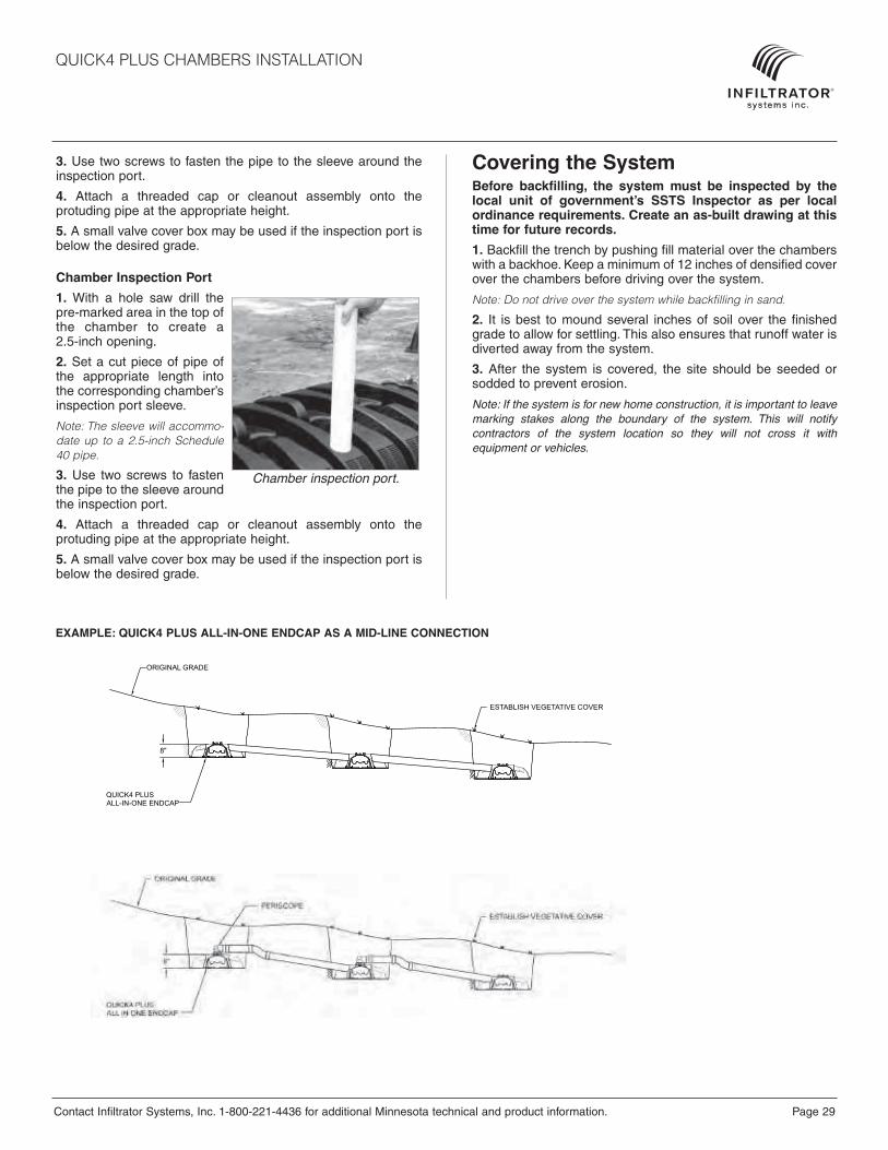
ORIGINAL GRADE
ORIGINAL GRADE
8"
EXAMPLE: QUICK4 PLUS ALL-IN-ONE ENDCAP AS A MID-LINE CONNECTION
QUICK4 PLUS CHAMBERS INSTALLATION

Page 30 Contact Infiltrator Systems, Inc. 1-800-221-4436 for additional Minnesota technical and product information.
QUICK4 PLUS CHAMBERS INSTALLATION
Pressure Systems
Installing Chambers and End Caps1. To allow pressure laterals to drain after each dose, drill a holein the bottom of the pipe at the end of the pressure line. Placethe snap-off splash plate or a paving block at the bottom of thetrench to protect the infiltrative surface from erosion.
2. With a hole saw, drill outthe appropriate diameterhole to accommodate thepressure lateral pipe.
3. Insert the pressure lateralpipe into the end cap’s drilledopening and slide it into themanifold pipe. Glue thepressure lateral pipe to themanifold pipe.
4. With the pressure lateral pipe through the end cap, place theback edge of the end cap over the inlet end of the first chamber.Be sure to line up the locking pins on the top of both thechamber and end cap.
Before You BeginQuick4 Plus chambers can only be installed according tostate and/or local regulations. Soil and site conditions mustbe approved prior to installation. Conduct a thorough siteevaluation to determine proper sizing and siting of thesystem before installation.
Materials and Equipment Needed
Quick4 Plus ChambersQuick4 Plus All-in-One or Q4 Plus EndcapsPVC Pipe and CouplingsBackhoeLaser, Transit or LevelTape measure
Shovel and RakeUtility Knife1 1/4-inch Drywall Screws*Screw Gun*Small Valve-cover Box*4-inch Cap Inspection Port
* Optional
These guidelines for construction machinery must befollowed during installation:
Avoid direct contact with chambers when using construc-tion equipment. Chambers require a 12-inch minimum ofcompacted cover to support a wheel load rating of 16,000lbs/axle or equivalent to an H-10 AASHTO load rating.
Only drive across the trenches when necessary. Neverdrive wheeled machinery over chambers.
Avoid stones larger than 3 inches in diameter in backfill.Remove stones this size or larger that are in contact withchambers.
2
Drill pressure pipe hole.
1" PRESSURE LATERAL (TYP.)
2" PRESSURE LATERAL (TYP.)
5. Secure the pressure lateralpipe to the top of the firstchamber with a plastic pipestrap at the outlet end of theunit. Slide the strap upthrough a slot in the chambertop, down through the otherslot, and cinch the two endsaround the pipe.
6. Lift and place the nextchamber onto the previousone at a 45-degree angle.Line up the chamber endbetween the connector hookand locking pin at the top of the first chamber. Lower it to theground to engage the interlocks.
7. Secure the lateral pipe to the top of the next chamber once inplace. Follow the same method in Step 5.
8. Continue interlocking chambers and securing the pipe untilthe trench is completed.
9. Before attaching the final end cap, it may be necessary toremove the tongue of the connector hook on the last chamberwith a pair of pliers depend-ing on your pipe diameter.
10. Insert the pressure lateralpipe through the hole in thefinal end cap and slide theend cap toward the lastchamber. Lift the end capover the modified connectorhook and push straight downto secure it to the chamber.
Note: If cleanout extensions arerequired, use a hole saw to cut ahole in the top of the Quick4Plus All-in-One Endcap so thepressure lateral pipe with anelbow can extend to the groundsurface. For cleanout access,use the “Installing OptionalInspection Ports” section in thegeneral installation instructions.
5
Secure pressure pipe.
VALVE BOX (OR IRRIGATION BOX)
ACCESS FOR DRAINFIELD MAINTENANCE AND FLUSHING
QUICK4 PLUS STANDARD LP
10
Lateral pipe through end cap.
Note: Health departments mayrequire a wet-run pressure checkto be done prior to chamberinstallation when the pipe is lay-ing on the ground. Check withyour local health department forthe proper procedure.
4
Place end cap over inlet end.

Contact Infiltrator Systems, Inc. 1-800-221-4436 for additional Minnesota technical and product information. Page 31
QUICK4 PLUS CHAMBERS INSTALLATION
Advantages of Method A
• Pipe and orifice placed closer to the chamber dome offer improved distribution.
• Pipe positioned at the top of the chamber places it wellabove effluent.
• Plastic pipe hanger easily secures pipe in place.
Advantage of Method B
• Pipe resting on the trench bottom allows easy installationand maintenance.
• Stabilizing “T’s” keep pipe level.
• System promotes efficient pressure checks.
• Pipe resting on the trench bottom allows easier inspectionsif monitoring ports are installed.
QUICK4 PLUS STANDARD LP CHAMBER
34"
8"
ALL WEATHER PLASTIC PIPE STRAP WITH120 POUNDS TENSILE STRENGTH AT EVERYCHAMBER CONNECTION
PRESSURE PIPE WITH HOLES AT 12 O’CLOCK(MAY BE INSTALLED ON EITHER SIDE)
STABILIZE OR "T" EVERY 10' TO PREVENT PIPE ROTATION AND MAINTAIN PROPER PIPE POSITION
34"
8"
QUICK4 PLUS STANDARD LP CHAMBER
PRESSURE PIPE WITH HOLES AT 12 O’CLOCK(MAY BE INSTALLED ON EITHER SIDE)

P.O. Box 768 • 6 Business Park Road • Old Saybrook, CT 06475 860-577-7000 • FAX 860-577-7001
www.infiltratorsystems.com1-800-221-4436
U.S. Patents: 4,759,661; 5,017,041; 5,156,488; 5,336,017; 5,401,116; 5,401,459; 5,511,903; 5,716,163; 5,588,778; 5,839,844 Canadian Patents: 1,329,959; 2,004,564 Other patents pending. Infiltrator, Equalizer, and Quick4 are registered trademarks of Infiltrator Systems Inc. Infiltrator is a registered trademark in France. Infiltrator Systems Inc. is a registered trademark in Mexico.ChamberSpacer, Contour, Contour Swivel Connection, MicroLeaching, MultiPort, PolyTuff, PosiLock, QuickCut, QuickPlay, SnapLock and Quick4 Plus are trademarks of Infiltrator Systems Inc. © 2009 Infiltrator Systems Inc. All rights reserved. Printed in U.S.A.
C991009ISI-0
One Year Standard Warranty
(a) The structural integrity of each chamber, end plate, wedge and other accessory manufactured by Infiltrator (collectively referred to as “Units”), when installed and operated in a leachfield of anonsite septic system in accordance with Infiltrator's installation instructions, is warranted to the original purchaser (“Holder”) against defective materials and workmanship for one year from the dateupon which a septic permit is issued for the septic system containing the Units; provided, however, that if a septic permit is not required for the septic system by applicable law, the one (1) year war-ranty period will begin upon the date that installation of the septic system commences. In order to exercise its warranty rights, Holder must notify Infiltrator in writing at its corporate headquarters inOld Saybrook, Connecticut within fifteen (15) days of the alleged defect. Infiltrator will supply replacement Units for those Units determined by Infiltrator to be defective and covered by this LimitedWarranty. Infiltrator’s liability specifically excludes the cost of removal and/or installation of the Units.
(b) THE LIMITED WARRANTY AND REMEDIES IN SUBPARAGRAPH (a) ARE EXCLUSIVE. THERE ARE NO OTHER WARRANTIES WITH RESPECT TO THE UNITS, INCLUDING NO IMPLIEDWARRANTIES OF MERCHANTABILITY OR FITNESS FOR A PARTICULAR PURPOSE.
(c) This Limited Warranty shall be void if any part of the chamber system (chamber, end plate, wedge or other accessory) is manufactured by anyone other than Infiltrator. The Limited Warranty doesnot extend to incidental, consequential, special or indirect damages. Infiltrator shall not be liable for penalties or liquidated damages, including loss of production and profits, labor and materials,overhead costs, or other losses or expenses incurred by the Holder or any third party. Specifically excluded from Limited Warranty coverage are damage to the Units due to ordinary wear and tear,alteration, accident, misuse, abuse or neglect of the Units; the Units being subjected to vehicle traffic or other conditions which are not permitted by the installation instructions; failure to maintain theminimum ground covers set forth in the installation instructions; the placement of improper materials into the system containing the Units; failure of the Units or the septic system due to impropersiting or improper sizing, excessive water usage, improper grease disposal, or improper operation; or any other event not caused by Infiltrator. This Limited Warranty shall be void if the Holder failsto comply with all of the terms set forth in this Limited Warranty.
Further, in no event shall Infiltrator be responsible for any loss or damage to the Holder, the Units, or any third party resulting from installation or shipment, or from any product liability claims of Holderor any third party. For this Limited Warranty to apply, the Units must be installed in accordance with all site conditions required by state and local codes; all other applicable laws; and Infiltrator’sinstallation instructions.
(d) No representative of Infiltrator has the authority to change this Limited Warranty in any manner whatsoever, or to extend this Limited Warranty. No warranty applies to any party other than theoriginal Holder.
* * * * * * *
The above represents the standard Limited Warranty offered by Infiltrator. A limited number of states and counties have different warranty requirements. Any purchaser of Units should contactInfiltrator's corporate headquarters in Old Saybrook, Connecticut, prior to such purchase, to obtain a copy of the applicable warranty, and should carefully read that warranty prior to the purchase ofUnits.
(a) Warranty. Infiltrator Systems Inc. warrants that each chamber, end plate, wedge and other accessories manufactured by Infiltrator (collectively, the "Units"), when installed and operated in a leach-field of an on-site septic system in accordance with the written instructions of Infiltrator Systems Inc. at the time of installation, and in accordance with the Minnesota Chamber Sizing Chart, are war-ranted for a period of five (5) years from date of installation (i) to be free from defective materials and workmanship, and (ii) to perform in accordance with the state and local leachfield performancerequirements in effect on the date of installation. For this Warranty to apply, the Units must be installed in accordance with Infiltrator Systems Inc.'s written installation instructions ("Instructions") andwith applicable state and local laws and regulations applicable to sewage disposal systems. In the event of a conflict or inconsistency between the Instructions and such laws and regulations, theInstructions shall take precedence over such laws and regulations, as permitted by Minnesota statute. The foregoing warranty is in lieu of all other warranties, expressed or implied, including but notlimited to implied warranties of merchantability and fitness for a particular purpose.
(b) Conditions Which Void Warranty. Infiltrator Systems Inc. does not warrant any Units not manufactured by Infiltrator Systems Inc. or for Infiltrator Systems Inc.; defects caused by failure to providea suitable installation environment for Units; failures to install the Units in accordance with Infiltrator Systems Inc.'s current written Instructions, damage resulting from improper sizing, excessive waterusage, improper grease disposal, or other improper use of the septic systems; damage resulting from improper siting of the septic system; damage arising from failure to maintain the septic tank inaccordance with the instructions of the tank manufacturer and Infiltrator Systems Inc.; damage caused by the Unit for purposes other than those for which it was designed; damage caused by abuse,misuse, or neglect by Buyer or any other party; damage to any Unit which has been subject to conditions, pressures, or stresses more severe than or exceeding those set forth in Infiltrator SystemsInc.'s written Instructions; damage caused by placement by Buyer or any other party of improper material into the Units; and damage from any other event not caused by Infiltrator Systems Inc. ThisWarranty shall also be void if Buyer fails to comply with Section C of this Warranty.
(c) Processing A Claim; Determination Of Warranty Coverage. Should a defect or failure of performance appear in the Warranty period, Buyer must notify Infiltrator Systems Inc. in writing of the defector failure of performance within fifteen (15) days of discovery of the defect or failure of performance. Notice shall be in writing and sent by registered or certified mail to Infiltrator Systems Inc., 6Business Park Road, P.O. Box 768, Old Saybrook, Connecticut 06475, attention Warranty Claims. The notice shall be accompanied by (i) a copy of the Infiltrator Warranty which is signed and datedby Buyer and Installer, as set forth below, (ii) a copy of the appropriate permit for the septic system, and (iii) documentation to Infiltrator Systems Inc.'s satisfaction that the septic tank has been main-tained in accordance with the instructions of the tank manufacturer and of Infiltrator Systems Inc. Infiltrator Systems Inc. will investigate the Warranty claim and will use its best efforts to notify Buyerof its findings within thirty (30) days of receipt of the claim. At its option, Infiltrator Systems Inc. may perform tests to determine the cause of the failure. For claims which Infiltrator Systems Inc. deter-mines are valid claims, Infiltrator Systems Inc. will pay the costs of redesign, if necessary, replacement Units, material, and labor costs for installing new Units, with the installation to be performedby a contractor selected by Infiltrator Systems Inc. This paragraph states Buyer's sole remedy for defective Units and performance failures, and Infiltrator Systems Inc. shall have no responsibility orliability for other items associated with the septic system.
(d) Original Installation Is Buyer's Responsibility. Buyer shall be solely responsible for ensuring that the original installation of the Units is completed in accordance with all applicable laws, codes,rules, and regulations.
(e) Limitation Of Liability. In no case shall Infiltrator Systems Inc. be liable for incidental, consequential, indirect, or special damages based upon breach of warranty, breach of contract, negligence,strict tort, or any other legal theory. Infiltrator Systems Inc. shall not be liable for any penalties or liquidated damages, including without limitation loss of production or profits, labor and materials(except as provided in Section C), overhead costs, claims of third parties, injury to property, or other losses or expenses incurred by Buyer.
(f) Sole Warranty; No Changes Authorized. The Warranty described above is the sole warranty offered by Infiltrator Systems Inc. Infiltrator Systems Inc. does not assume any other liability in con-nection with the sale of the Units. No representative of Infiltrator Systems Inc. is allowed to extend this Warranty or to change it in any manner whatsoever.
Minnesota Five Year Warranty


