Infilex FC Fan Coil Unit Controller Models WY5305W1000 … · Fan Coil Unit Controller Models...
28
AB-6569 ∗Yamatake’s controller Infilex series: Infilex is named for “Infinity” and “Flexible.” 1 Specifications/Instructions Infilex ™ FC Fan Coil Unit Controller Models WY5305W1000-X, WY5305W2010-X General Infilex FC (Infilex: named for “Infinity” and “Flexible”) Model WY5305 provides digital control of FCUs (fan coil units). In addition to FCU start/stop operation, valve control, and fan speed changeover, Infilex FC provides advanced controls such as setback and interlock operations with OAHU (outdoor air handling unit). Infilex FC can interface with user terminals to allow the end users to operate the FCU. Infilex FC can communicate with the integrated BMS (building management system), Yamatake’s savic-net ™ FX. That is, scheduled operation, operating status, and temperature measurement of the FCU can be centrally monitored and controlled from the BMS main control unit. Features • Compact size Small sized body fits inside an FCU. • Easy installation Connectors facilitate wiring installation. • Two kinds of FCU control Valve ON/OFF control and valve proportional control for FCU are available. • Various connectable terminals In addition to the temperature sensor, digital and analog user terminals can be connected to Infilex FC. • LONMARK ® certified product FCU control network is configured with LonTalk ® protocol. Infilex FC is LONMARK ® (version 3.4) certified and thus interoperable integrated in the LONWORKS ® system. Model Numbers Model number Description WY5305 Base model number W 100 V AC to 240 V AC power 1 0 0 0 Valve ON/OFF control, with DI (digital input) × 0 pt. 2 0 1 0 Valve proportional control, with DI (digital input) × 2 pts. -0 LONMARK uncertified -1 LONMARK certified
Transcript of Infilex FC Fan Coil Unit Controller Models WY5305W1000 … · Fan Coil Unit Controller Models...

AB-6569
∗Yamatake’s controller Infilex series: Infilex is named for “Infinity” and “Flexible.” 1
Specifications/Instructions
Infilex™ FC
Fan Coil Unit Controller Models WY5305W1000-X, WY5305W2010-X
General Infilex FC (Infilex: named for “Infinity” and “Flexible”) Model WY5305 provides digital control of FCUs (fan coil units). In addition to FCU start/stop operation, valve control, and fan speed changeover, Infilex FC provides advanced controls such as setback and interlock operations with OAHU (outdoor air handling unit).
Infilex FC can interface with user terminals to allow the end users to operate the FCU.
Infilex FC can communicate with the integrated BMS (building management system), Yamatake’s savic-net™ FX. That is, scheduled operation, operating status, and temperature measurement of the FCU can be centrally monitored and controlled from the BMS main control unit.
Features • Compact size
Small sized body fits inside an FCU.
• Easy installation Connectors facilitate wiring installation.
• Two kinds of FCU control Valve ON/OFF control and valve proportional control for FCU are available.
• Various connectable terminals
In addition to the temperature sensor, digital and analog user terminals can be connected to Infilex FC.
• LONMARK® certified product FCU control network is configured with LonTalk® protocol. Infilex FC is LONMARK® (version 3.4) certified and thus interoperable integrated in the LONWORKS® system.
Model Numbers Model number Description
WY5305 Base model number
W 100 V AC to 240 V AC power
1 0 0 0 Valve ON/OFF control, with DI (digital input) × 0 pt. 2 0 1 0 Valve proportional control, with DI (digital input) × 2 pts.
-0 LONMARK uncertified -1 LONMARK certified
2 AB-6569
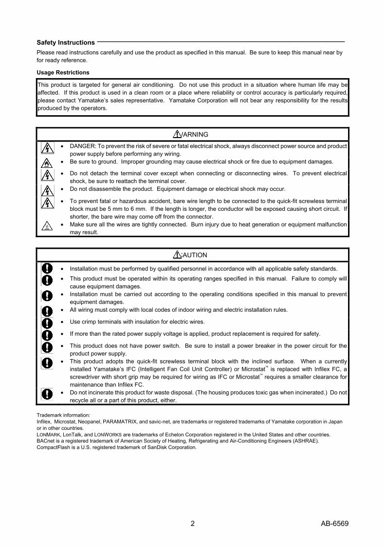
Safety Instructions Please read instructions carefully and use the product as specified in this manual. Be sure to keep this manual near by for ready reference.
Usage Restrictions
This product is targeted for general air conditioning. Do not use this product in a situation where human life may be affected. If this product is used in a clean room or a place where reliability or control accuracy is particularly required, please contact Yamatake’s sales representative. Yamatake Corporation will not bear any responsibility for the results produced by the operators.
WARNING
• DANGER: To prevent the risk of severe or fatal electrical shock, always disconnect power source and product
power supply before performing any wiring.
• Be sure to ground. Improper grounding may cause electrical shock or fire due to equipment damages.
• Do not detach the terminal cover except when connecting or disconnecting wires. To prevent electrical
shock, be sure to reattach the terminal cover.
• Do not disassemble the product. Equipment damage or electrical shock may occur.
• To prevent fatal or hazardous accident, bare wire length to be connected to the quick-fit screwless terminal
block must be 5 mm to 6 mm. If the length is longer, the conductor will be exposed causing short circuit. If shorter, the bare wire may come off from the connector.
• Make sure all the wires are tightly connected. Burn injury due to heat generation or equipment malfunction
may result.
CAUTION
• Installation must be performed by qualified personnel in accordance with all applicable safety standards.
• This product must be operated within its operating ranges specified in this manual. Failure to comply will
cause equipment damages.
• Installation must be carried out according to the operating conditions specified in this manual to prevent
equipment damages.
• All wiring must comply with local codes of indoor wiring and electric installation rules.
• Use crimp terminals with insulation for electric wires.
• If more than the rated power supply voltage is applied, product replacement is required for safety.
• This product does not have power switch. Be sure to install a power breaker in the power circuit for the
product power supply.
• This product adopts the quick-fit screwless terminal block with the inclined surface. When a currently
installed Yamatake’s IFC (Intelligent Fan Coil Unit Controller) or Microstat™ is replaced with Infilex FC, a screwdriver with short grip may be required for wiring as IFC or Microstat™ requires a smaller clearance for maintenance than Infilex FC.
• Do not incinerate this product for waste disposal. (The housing produces toxic gas when incinerated.) Do not
recycle all or a part of this product, either. Trademark information: Infilex, Microstat, Neopanel, PARAMATRIX, and savic-net, are trademarks or registered trademarks of Yamatake corporation in Japan or in other countries. LONMARK, LonTalk, and LONWORKS are trademarks of Echelon Corporation registered in the United States and other countries. BACnet is a registered trademark of American Society of Heating, Refrigerating and Air-Conditioning Engineers (ASHRAE). CompactFlash is a U.S. registered trademark of SanDisk Corporation.

3 AB-6569
System Configurations
Infilex FC combined with BMS (with Web browser) BACnet® / IP LC-bus*5 (LonTalk® protocol) ∗1. SMS: System Management Server ∗2. SCS: System Core Server ∗3. PMX-III: PARAMATRIX™-III ∗4. IAC: Intelligent AHU (air handling unit) Controller ∗5. LC-bus: LonTalk Controller Bus ∗6. LS-bus: LonTalk Sub-Controller Bus LS-bus*6 (LonTalk® protocol) Neopanel™ Neoplate (Digital user terminal) (Analog user terminal)
Figure 1. System configuration example of BMS-integrated Infilex FC Notes: ∗ On LC-bus (2 lines for 1 channel), max. 50 remote units (also called ‘controllers’) can be connected. For Infilex ZM, however, max.
10 units can be connected on LC-bus (5 units per 1line, 2 lines for 1 channel). ∗ Max. wiring length of LC-bus (2 lines for 1 channel) is 900 m. ∗ On LS-bus, max. 50 remote units (also called ‘sub-controllers’) can be connected. ∗ Max. wiring length of LS-bus is 900 m.
Specifications
Basic specifications Item Specification
Power supply 100 V AC to 240 V AC (85 V AC to 264 V AC) at 50 Hz/60 Hz Power consumption Valve ON/OFF control type (Model WY5305W1000-X): Max. 6 VA
Valve proportional control type (Model WY5305W2010-X): Max. 7 VA Operating environmental conditions Temperature:
Humidity: Vibration:
0 °C to 50 °C 10 %RH to 90 %RH (non-condensing) Max. 3.2 m/s² (at 10 Hz to 150 Hz)
Transport/storage conditions Temperature: Humidity: Vibration:
-20 °C to 60 °C 5 %RH to 95 %RH (non-condensing) Max. 3.2 m/s² (at 10 Hz to 150 Hz) for transport Max. 9.8 m/s² (at 10 Hz to 150 Hz) for storage
Mounting Screw-on with two M4 × 10 screws Address setting Rotary switch setting Weight Valve ON/OFF control type: 250 g (main unit only)
Valve proportional control type: 450 g (main unit only)
SMS*1
Computer for monitoring
SCS*2
Infilex™ ACModel WY5317C
Infilex™ GCModel WY5311
Infilex™ GDModel WY5310
PMX-III*3 Model WY7400
Infilex™ ZMModel WY5322
IAC*4
Model WY7307Infilex™ FC
Model WY5305Infilex™ VC
Model WY5306
4 AB-6569
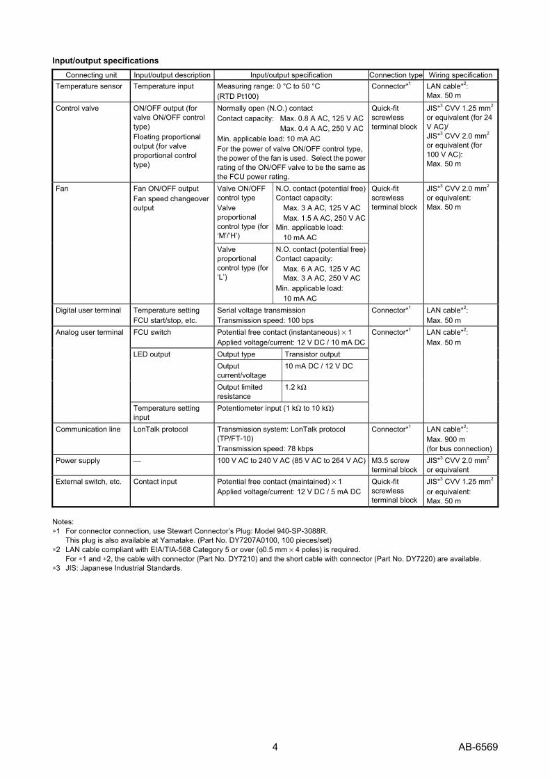
Input/output specifications Connecting unit Input/output description Input/output specification Connection type Wiring specification
Temperature sensor Temperature input Measuring range: 0 °C to 50 °C (RTD Pt100)
Connector*1 LAN cable*2: Max. 50 m
Control valve ON/OFF output (for valve ON/OFF control type) Floating proportional output (for valve proportional control type)
Normally open (N.O.) contact Contact capacity: Max. 0.8 A AC, 125 V AC Max. 0.4 A AC, 250 V ACMin. applicable load: 10 mA AC For the power of valve ON/OFF control type, the power of the fan is used. Select the power rating of the ON/OFF valve to be the same as the FCU power rating.
Quick-fit screwless terminal block
JIS*3 CVV 1.25 mm2 or equivalent (for 24 V AC)/ JIS*3 CVV 2.0 mm2
or equivalent (for 100 V AC): Max. 50 m
Valve ON/OFF control type Valve proportional control type (for ‘M’/’H’)
N.O. contact (potential free) Contact capacity:
Max. 3 A AC, 125 V ACMax. 1.5 A AC, 250 V AC
Min. applicable load: 10 mA AC
Fan Fan ON/OFF output Fan speed changeover output
Valve proportional control type (for ‘L’)
N.O. contact (potential free) Contact capacity:
Max. 6 A AC, 125 V AC Max. 3 A AC, 250 V AC
Min. applicable load: 10 mA AC
Quick-fit screwless terminal block
JIS*3 CVV 2.0 mm2
or equivalent: Max. 50 m
Digital user terminal Temperature setting FCU start/stop, etc.
Serial voltage transmission Transmission speed: 100 bps
Connector*1 LAN cable*2: Max. 50 m
FCU switch Potential free contact (instantaneous) × 1 Applied voltage/current: 12 V DC / 10 mA DC Output type Transistor output Output current/voltage
10 mA DC / 12 V DC LED output
Output limited resistance
1.2 kΩ
Analog user terminal
Temperature setting input
Potentiometer input (1 kΩ to 10 kΩ)
Connector*1 LAN cable*2: Max. 50 m
Communication line LonTalk protocol Transmission system: LonTalk protocol (TP/FT-10) Transmission speed: 78 kbps
Connector*1 LAN cable*2: Max. 900 m (for bus connection)
Power supply ⎯ 100 V AC to 240 V AC (85 V AC to 264 V AC) M3.5 screw terminal block
JIS*3 CVV 2.0 mm2
or equivalent External switch, etc. Contact input Potential free contact (maintained) × 1
Applied voltage/current: 12 V DC / 5 mA DCQuick-fit screwless terminal block
JIS*3 CVV 1.25 mm2
or equivalent: Max. 50 m
Notes: ∗1 For connector connection, use Stewart Connector’s Plug: Model 940-SP-3088R.
This plug is also available at Yamatake. (Part No. DY7207A0100, 100 pieces/set) ∗2 LAN cable compliant with EIA/TIA-568 Category 5 or over (φ0.5 mm × 4 poles) is required.
For ∗1 and ∗2, the cable with connector (Part No. DY7210) and the short cable with connector (Part No. DY7220) are available. ∗3 JIS: Japanese Industrial Standards.
5 AB-6569
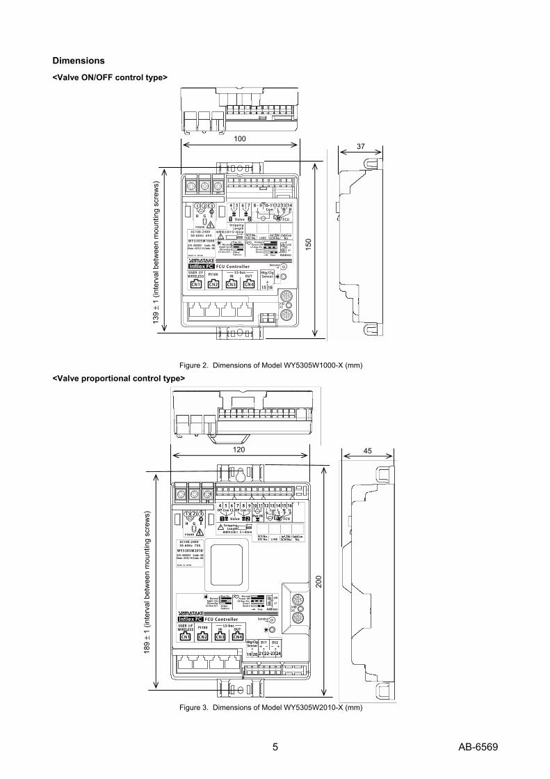
Dimensions
<Valve ON/OFF control type>
Figure 2. Dimensions of Model WY5305W1000-X (mm)
<Valve proportional control type>
Figure 3. Dimensions of Model WY5305W2010-X (mm)
10037
139
± 1
(inte
rval
bet
wee
n m
ount
ing
scre
ws)
150
120 45
189
± 1
(inte
rval
bet
wee
n m
ount
ing
scre
ws)
200
6 AB-6569
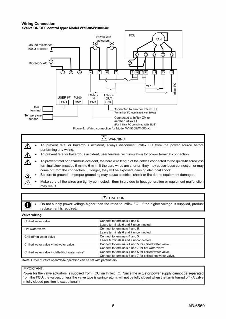
Wiring Connection <Valve ON/OFF control type: Model WY5305W1000-X>
Figure 4. Wiring connection for Model WY5305W1000-X
WARNING
• To prevent fatal or hazardous accident, always disconnect Infilex FC from the power source before
performing any wiring.
• To prevent fatal or hazardous accident, user terminal with insulation for power terminal connection.
• To prevent fatal or hazardous accident, the bare wire length of the cables connected to the quick-fit screwless
terminal block must be 5 mm to 6 mm. If the bare wires are shorter, they may cause loose connection or may come off from the connectors. If longer, they will be exposed, causing electrical shock.
• Be sure to ground. Improper grounding may cause electrical shock or fire due to equipment damages.
• Make sure all the wires are tightly connected. Burn injury due to heat generation or equipment malfunction
may result.
CAUTION
• Do not supply power voltage higher than the rated to Infilex FC. If the higher voltage is supplied, product
replacement is required.
Valve wiring
Chilled water valve Connect to terminals 4 and 5. Leave terminals 6 and 7 unconnected.
Hot water valve Connect to terminals 4 and 5. Leave terminals 6 and 7 unconnected.
Chilled/hot water valve Connect to terminals 4 and 5. Leave terminals 6 and 7 unconnected.
Chilled water valve + hot water valve Connect to terminals 4 and 5 for chilled water valve. Connect to terminals 6 and 7 for hot water valve.
Chilled water valve + chilled/hot water valve* Connect to terminals 4 and 5 for chilled water valve. Connect to terminals 6 and 7 for chilled/hot water valve.
∗Note: Order of valve open/close operation can be set with parameters. IMPORTANT: Power for the valve actuators is supplied from FCU via Infilex FC. Since the actuator power supply cannot be separated from the FCU, the valves, unless the valve type is spring-return, will not be fully closed when the fan is turned off. (A valve in fully closed position is exceptional.)
User terminal
Temperature sensor
FAN FCU
100-240 V AC
Ground resistance: 100 Ω or lower
∼
Valves with actuators
∼
14 13 121198 101 2 3 754 6
Connected to another Infilex FC (For Infilex FC combined with BMS)
Connected to Infilex ZM or another Infilex FC (For Infilex FC combined with BMS)
Infil
ex F
C
CN1 CN2 CN3 CN4USER I/F Pt100
LS-busIN
LS-busOUT

7 AB-6569
<Valve proportional control type: Model WY5305W2010-X>
Figure 5. Wiring connection for Model WY5305W2010-X
WARNING
• To prevent fatal or hazardous accident, always disconnect Infilex FC from the power source before
performing any wiring.
• To prevent fatal or hazardous accident, user terminal with insulation for power terminal connection.
• To prevent fatal or hazardous accident, the bare wire length of the cables connected to the quick-fit screwless
terminal block must be 5 mm to 6 mm. If the bare wires are shorter, they may cause loose connection or may come off from the connectors. If longer, they will be exposed, causing electrical shock.
• Be sure to ground. Improper grounding may cause electric shock or fire due to equipment damages.
• Make sure all the wires are tightly connected. Burn injury due to heat generation or equipment malfunction
may result.
CAUTION
• Do not supply power voltage higher than the rated to Infilex FC. If the higher voltage is supplied, product
replacement is required.
Valve wiring Chilled water valve Connect to terminals 4, 5 and 6.
Leave terminals 7, 8 and 9 unconnected. Hot water valve Connect to terminals 4, 5 and 6.
Leave terminals 7, 8 and 9 unconnected. Chilled/hot water valve Connect to terminals 4, 5 and 6.
Leave terminals7, 8 and 9 unconnected. Chilled water valve + hot water valve Connect to terminals 4, 5 and 6 for chilled water valve.
Connect to terminals 7, 8 and 9 for hot water valve. Chilled water valve + chilled/hot water valve* Connect to terminals 4, 5 and 6 for chilled water valve.
Connect to terminals7, 8 and 9 for chilled/hot water valve. ∗Note: Order of valve open/close operation can be set with parameters. IMPORTANT: If Infilex FC is used in a 24-hour operation system, be sure to fully close/open the valves at least once a day. (The valves can be forcibly opened/closed with parameter setting.)
∗ Note: Provide a transformer when necessary.
FAN
16 15 1312111 2 3 5 4 6
100-240 V AC
Ground resistance: 100 Ω or lower
∼
CN1 CN2 CN3 CN4USER I/F Pt100
LS-busIN
LS-busOUT
Connected to another Infilex FC (For Infilex FC combined with BMS)
Connected to Infilex ZMor another Infilex FC
(For Infilex FC combined with BMS)
User terminal
Temperature sensor
Ope
n
Clo
se
H L M
FCU power monitoring
circuit
10
CO
M
87 9
Ope
n
Clo
se
CO
M
14
2321 24 22
DI × 2 pts. (Only for Model WY5305W2010)
DI1 DI2
CO
M
Infil
ex F
C
(For standalone Infilex FC)
FCU
∗See
not
e.
Valves with actuators
∼∼

8 AB-6569
Installation / Wiring 1) Open the mounting hole.
Open two holes for M4 screws with a 139 mm ± 1 mm interval for valve ON/OFF control type / a 189 mm ± 1 mm interval for valve proportional control type.
Figure 6. Interval between M4 screw holes
2) Mount Infilex FC with two M4 screws. Make sure that Infilex FC is fixed with the screws.
Figure 7. Mounting Infilex FC with two M4 screws
3) Mounting bracket (Part No. DY7208A0001 for small size, Part No. DY7208A0002 for large size) for IFC (Intelligent FCU Controller) and IVC (Intelligent VAV Controller) is applicable to fix Infilex FC as well.
To mount Infilex FC on a threaded rod (φ9 mm) in the ceiling, use two cable ties. Put a cable tie through two holes on the bilateral sides of the M4 screw hole, located on the top and the bottom of Infilex FC. Instead of cable ties, two fasteners can be used to mount Infilex FC on the threaded rod. (Refer to Fig. 8.)
Infilex FC mounted on the threaded rod may rotate on the threaded rod as an axis. Do not allow the tension on the cables when wiring.
Figure 8. Mounting Infilex FC on an threaded rod
4) Crimp M3.5 crimp terminals on the power cable, and
connect them to the screw terminal block.
Connect modular cables for LS-bus, for the user terminal(s), and/or for the temperature sensor(s) to the modular jacks until they click. Pull lightly out the cables to make sure the modular plugs are completely connected to the modular jacks.
IMPORTANT: Do not apply 98 N⋅cm or more torque for connecting the screw terminals.
WARNING • To prevent electrical shock, be sure to turn
off the power supply to Infilex FC before connecting the power cable.
5) Connect the cables to the quick-fit screwless (clamp)
terminal blocks as follows:
1. Insert a slotted screwdriver into a smaller square hole (for clamp release) on the terminal blocks located on the upper and the lower sides of the front surface.
2. Tilt the screwdriver while pushing it into the hole. (Make sure the direction to tilt in Fig. 9.) When the screwdriver is proceeded to the deep end, the clamp is completely released.
3. Insert a bare wire (5-6 mm long) into a larger square hole.
4. Pull out the screwdriver with the bare wire inserted.
Figure 9. Connecting a wire to the quick-fit screwless terminal block
Note: Regarding the wiring for FCU ON/OFF output and control
valve output, refer to P. 10.
Two mounting holes for M4 screws
139 ± 1 mm: Valve ON/OFF control type 189 ± 1 mm: Valve proportional control type
189±
1mm
139 ±
1mm
1. 4.
2.
3.
Releasing the clamp: When pushing the screwdriver, tilt it along the curving surface inside the square hole. Cable tie
Fastener
9 AB-6569
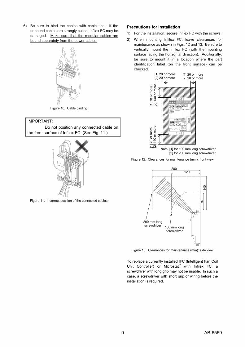
6) Be sure to bind the cables with cable ties. If the unbound cables are strongly pulled, Infilex FC may be damaged. Make sure that the modular cables are bound separately from the power cables.
Figure 10. Cable binding
IMPORTANT: Do not position any connected cable on the front surface of Infilex FC. (See Fig. 11.)
Figure 11. Incorrect position of the connected cables
Precautions for Installation 1) For the installation, secure Infilex FC with the screws.
2) When mounting Infilex FC, leave clearances for maintenance as shown in Figs. 12 and 13. Be sure to vertically mount the Infilex FC (with the mounting surface facing the horizontal direction). Additionally, be sure to mount it in a location where the part identification label (on the front surface) can be checked.
Figure 12. Clearances for maintenance (mm): front view
Figure 13. Clearances for maintenance (mm): side view
To replace a currently installed IFC (Intelligent Fan Coil Unit Controller) or Microstat™ with Infilex FC, a screwdriver with long grip may not be usable. In such a case, a screwdriver with short grip or wiring before the installation is required.
200 120
140
70
100 mm long screwdriver
200 mm long screwdriver
[1] 7
0 or
mor
e [2
] 140
or m
ore
[1] 20 or more [2] 20 or more
[1] 20 or more[2] 20 or more
[1] 7
0 or
mor
e [2
] 140
or m
ore
Note: [1] for 100 mm long screwdriver [2] for 200 mm long screwdriver
10 AB-6569
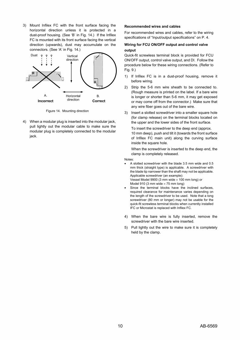
3) Mount Infilex FC with the front surface facing the horizontal direction unless it is protected in a dust-proof housing. (See ‘B’ in Fig. 14.) If the Infilex FC is mounted with its front surface facing the vertical direction (upwards), dust may accumulate on the connectors. (See ‘A’ in Fig. 14.)
Figure 14. Mounting direction
4) When a modular plug is inserted into the modular jack, pull lightly out the modular cable to make sure the modular plug is completely connected to the modular jack.
Recommended wires and cables For recommended wires and cables, refer to the wiring specifications of “Input/output specifications” on P. 4.
Wiring for FCU ON/OFF output and control valve output Quick-fit screwless terminal block is provided for FCU ON/OFF output, control valve output, and DI. Follow the procedure below for these wiring connections. (Refer to Fig. 9.)
1) If Infilex FC is in a dust-proof housing, remove it before wiring.
2) Strip the 5-6 mm wire sheath to be connected to. (Rough measure is printed on the label. If a bare wire is longer or shorter than 5-6 mm, it may get exposed or may come off from the connector.) Make sure that any wire fiber goes out of the bare wire.
3) Insert a slotted screwdriver into a smaller square hole (for clamp release) on the terminal blocks located on the upper and the lower sides of the front surface.
To insert the screwdriver to the deep end (approx. 10 mm deep), push and tilt it (towards the front surface of Infilex FC main unit) along the curving surface inside the square hole.
When the screwdriver is inserted to the deep end, the clamp is completely released.
Notes: • A slotted screwdriver with the blade 3.5 mm wide and 0.5
mm thick (straight type) is applicable. A screwdriver with the blade tip narrower than the shaft may not be applicable.
Applicable screwdriver (an example): Vessel Model 9900 (3 mm wide × 100 mm long) or Model 910 (3 mm wide × 75 mm long)
• Since the terminal blocks have the inclined surfaces, required clearance for maintenance varies depending on the length of the screwdriver to be used. Note that a long screwdriver (80 mm or longer) may not be usable for the quick-fit screwless terminal blocks when currently installed IFC or Microstat is replaced with Infilex FC.
4) When the bare wire is fully inserted, remove the
screwdriver with the bare wire inserted.
5) Pull lightly out the wire to make sure it is completely held by the clamp.
Vertical direction
A. B.
Dust
Incorrect CorrectHorizontal direction

11 AB-6569
Note for the wiring connection of bare wires with 1.8 mm2 or smaller cross section
On the terminal block, a connector where a bare wire with 1.8 mm2 or smaller cross section is connected may cause short-circuit due to the dust accumulated in the clearance of the connector. (See Fig. 15.)
To prevent short-circuit, put the tubes (Part No. 83167219-001, 6 pieces/set) through the wires so that the connectors are covered. (See Fig. 16.) If the tubes are necessary, be sure to separately order as it is not included in Infilex FC.
Figure 15. Dust accumulated in the connector where the bare wires are connected
Figure 16. Tubes
Connection to user terminal / temperature sensor Wiring connection between user terminal / temperature sensor and Infilex FC adopts modular connector. For correct modular plug connection to modular jack, refer to the following section.
Modular connector connection Modular connector is composed of a modular plug (male) and a modular jack (female). Modular jacks are provided on Infilex FC, and modular plugs will be crimped on LAN cables as required. Refer to the following procedure for crimping the modular plugs on the LAN cables and connecting them to the modular jacks. Note: For modular plugs, refer to ‘Note ∗1’ on P.4.
Procedure for modular connector connection 1) Strip the outer sheath of a LAN cable end. Be sure not
to scratch or peel off any inner conductor sheath when stripping the outer sheath.
Figure 17. Stripping the outer sheath
Make sure there are 8 inner conductors inside the outer sheath.
2) Align the 8 inner conductors in a order specified by the LAN cable manufacturer.
Figure 18. Alignment of the inner conductors Alignment of the LAN cable inner conductors is shown
in the table below. Modular plug pin
number
LAN cable inner conductor alignment
Color alignment example
1 Line 1
of pair 2 Orange
2 Line 2
of pair 2 White & orange
3 Line 1
of pair 3 Green
4 Line 2
of pair 1 Blue & white
5 Line 1
of pair 1 Blue
6 Line 2
of pair 3 Green & white
7 Line 1
of pair 4 Brown
8 Line 2
of pair 4 Brown & white
Note: The color alignment shown above may not agree with your LAN cable specification. Ask your LAN cable manufacturer for the latest specification.
8 inner conductors
LAN cable
LAN cable
Pin numbers 12345678
Dust
Tubes (Part No. 83167219-001)

12 AB-6569
3) Insert the aligned inner conductors into a modular plug.
Figure 19. LAN cable insertion into a modular plug
Pin numbers of the modular plug in Fig. 19 shows the
pin number arrangement when you face the side with contacts and cable stopper.
Before inserting the inner conductors into the modular plug, even out the length with a nipper. Note that the modular plug may not be crimped on inner conductors stripped too long.
4) Crimp the modular plug with the crimping tool. Completely insert the inner conductors into the modular plug so that the contacts of the modular plug stick into the inner conductors when the modular plug is crimped. Crimped modular plug is secured on the LAN cable with the cable stopper of the modular plug. Check the contacts and the cable stopper when crimping the modular plug.
5) Follow 1) to 4) for the other end of the LAN cable.
6) Check continuity of the LAN cable. Modular continuity tester (Part No. DY7206A0000) facilitates the continuity check. At the same time, make sure that the inner conductors are in order with the modular plug contacts sticking in the conductors and that there is no cable damage or disconnection.
7) Connect the modular plugs to the modular jacks. When the continuity check is successfully completed, insert one modular plug of the LAN cable into the modular jack of Infilex FC and the other modular plug into the modular jack of a user terminal / a temperature sensor.
Be sure to completely insert a modular plug until it clicks.
Parts
Figure 20. Modular branch unit: Part No. DY7203A0000
Figure 21. Modular extension unit: Part No. DY7202A0000
Figure 22. Bracket (small size): Part No. DY7208A0001
Figure 23. Bracket (large size): Part No. DY7208A0002
Figure 24. Adaptor for connecting to a Pt100 sensor: Part No. DY7204A0003
Figure 25. Adaptor for connecting to a user terminal: Part No. DY7204A0008
(Note that the adaptor for a user terminal is not necessary for connecting to a digital user terminal Model QY7205C.)
Figure 26. Modular plug: Part No. DY7207A0100
(100 pcs./set)
8 7
4 5
3
1 2
6 Cable side
Pin numbers of the modular plug
Cable stopper
Modular plug
Contacts Insert.
10 mm ± 3 mm (For the recommended modular plug)
LAN cable
Inte
rval
bet
wee
n m
ount
ing
scre
ws
Unit: mm
Unit: mm
Two M4 screws
φ4.5 (two holes)
φ4.5
φ5.5 (3 holes) M4 screw
M4 screw Unit: mm
M4 screw
φ5.5 (3 holes)
φ4.5
φ4.5
M4 screw Three M4 screws
Unit: mm

13 AB-6569
Figure 27. Tubes: Part No. 83167219-001 (6 pcs./set)
The parts are used as follows.
• Modular branch unit (See Fig. 20.): Used to branch out the communication line for two user terminals to be connected.
• Modular extension unit (See Fig. 21.): Used to extend the communication line by connecting to another communication line.
• Bracket (See Figs. 22 and 23): Used to mount Infilex FC main unit on FCU or on a threaded rod.
• Adaptor for connecting to a Pt100 sensor (See Fig. 24.): Used to connect a temperature sensor to Infilex FC with a modular connector.
• Adaptor for connecting to a user terminal (See Fig. 25.): Used to connect to an analog user terminal (with fan speed changeover)
• Tubes (Fig. 27): Used to cover clearance of the connectors where 1.8 mm2 or smaller wires are connected.
Precautions for use
• Modular branch unit, modular extension unit, adaptor for connecting to a Pt100 sensor, and adaptor for connecting to an user terminal must be used in an outlet box or inside a panel.
• For the modular connector connection, be sure to insert the modular plugs into the modular jacks until they click. Then, lightly pull out the cables to make sure they are completely connected.
• Brackets has two different sizes. A small sized bracket is used for mounting the valve ON/OFF control type Infilex FC, and a large sized bracket is used for mounting the valve proportional control type Infilex FC.
Recommended Infilex FC mounting with a bracket
Bracket (small size) Model DY7208A0001
Bracket (large size) Model DY7208A0002
Model WY5305W1000-X Model WY5305W2010-X
Tools
Figure 28. Modular crimping tool: Part No. DY7205A0002
Figure 29. Modular continuity tester: Part No. DY7206A0000
The tools are used as follows:
• Modular crimping tool (See Fig. 28.): Used to crimp a modular plug on a LAN cable.
• Modular continuity tester (See Fig. 29.): Used to check continuity of a LAN cable with modular plugs crimped on.
14 AB-6569
Terminator For LonTalk protocol, terminator is required to ensure the communication reliability. For bus topology, a terminator is connected at each end of the devices on the bus (= 2 terminators for bus topology). For free topology, a terminator is connected at any end of the devices on the bus (= 1 terminator for free topology) throughout the whole system.
IMPORTANT: Terminator types vary depending on network topology (bus topology or free topology). Refer to the table below.
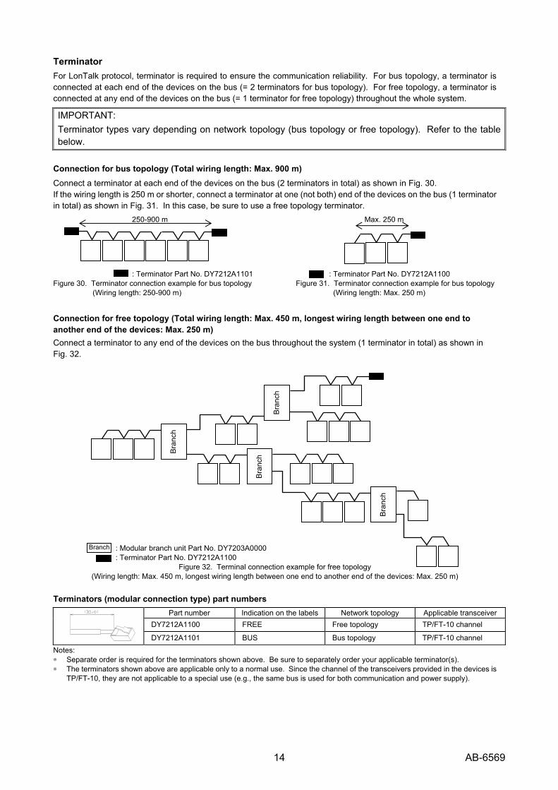
Connection for bus topology (Total wiring length: Max. 900 m) Connect a terminator at each end of the devices on the bus (2 terminators in total) as shown in Fig. 30. If the wiring length is 250 m or shorter, connect a terminator at one (not both) end of the devices on the bus (1 terminator in total) as shown in Fig. 31. In this case, be sure to use a free topology terminator. 250-900 m Max. 250 m
: Terminator Part No. DY7212A1101 : Terminator Part No. DY7212A1100 Figure 30. Terminator connection example for bus topology Figure 31. Terminator connection example for bus topology
(Wiring length: 250-900 m) (Wiring length: Max. 250 m)
Connection for free topology (Total wiring length: Max. 450 m, longest wiring length between one end to another end of the devices: Max. 250 m) Connect a terminator to any end of the devices on the bus throughout the system (1 terminator in total) as shown in Fig. 32.
: Modular branch unit Part No. DY7203A0000 : Terminator Part No. DY7212A1100
Figure 32. Terminal connection example for free topology (Wiring length: Max. 450 m, longest wiring length between one end to another end of the devices: Max. 250 m)
Terminators (modular connection type) part numbers Part number Indication on the labels Network topology Applicable transceiver
DY7212A1100 FREE Free topology TP/FT-10 channel
DY7212A1101 BUS Bus topology TP/FT-10 channel Notes: ∗ Separate order is required for the terminators shown above. Be sure to separately order your applicable terminator(s). ∗ The terminators shown above are applicable only to a normal use. Since the channel of the transceivers provided in the devices is
TP/FT-10, they are not applicable to a special use (e.g., the same bus is used for both communication and power supply).
Bra
nch
Bra
nch
Bra
nch
Bra
nch
Branch

15 AB-6569
Software Details Functions with the symbol * are available when Infilex FC is combined with Infilex ZM, other controllers, and the main control unit in a BMS.
(1/3) Item Function Description Remarks
FCU start/stop operation
FCU is turned on/off with the main control unit, DI, or a user terminal.
Each Infilex FC can individually be started up and shut down.
Setback operation Set temperature is changed to save energy. Each Infilex FC can individually perform the setback operation.
FCU interlocking with OAHU*
Infilex ZM can configure the sets composed of Infilex FC and AHU controller. (Multiple Infilex FC and AHU controllers can be included in a set.) In a specified set, all the FCUs interlock with the OAHU start/stop operation.
One Infilex ZM can control up to 4 sets.‘OAHU interlocking with FCU’ is not available when ‘FCU interlocking with OAHU’ is active. Do not operate the user terminal(s) to start/stop Infilex FC.
Operation (common to valve ON/OFF control and valve proportional control types)
OAHU interlocking with FCU*
Infilex ZM can configure the sets composed of Infilex FC and AHU controller. (Multiple Infilex FC and AHU controllers can be included in a set.) In a specified set, all the OAHUs interlock with FCU start/stop operation if at least one FCU is started up.
One Infilex ZM can control up to 4 sets.‘FCU interlocking with OAHU’ is not available when ‘OAHU interlocking with FCU’ is active.
Temperature control1)
Valve is ON/OFF-controlled so that the actual (measured) temperature matches the preset temperature.
Control (for valve ON/OFF control type)
Fan speed control The fan speed is multistage-controlled depending on the difference between the actual temperature and the preset temperature. Fan multistage control has L/M/H(low/medium/high) type or L/M/H/OFF type.
Fan speed is automatically controlled when it is set to AUTO. When L/M/H is selected, the selected fan speed is output.
Temperature control1)
Floating valve is PID-controlled so that the actual (measured) temperature matches the preset temperature.
Noise control To prevent the water flushing noise, the valve is completely closed when its closing position reaches the specified degree.
Control (for valve proportional control type)
Fan speed control The fan speed is multistage-controlled depending on the difference between the actual temperature and the preset temperature. Fan multi-stage control has L/M/H type or L/M/H/Off type. Water- or fan speed-priority control can be selected in response to the applications.2)
Fan speed is automatically controlled when it is set to AUTO. When L/M/H is selected, the selected fan speed is output.
Cooling/heating changeover*
The following items are sent from the main control unit when cooling/heating changeover is required: Cooling enabled, heating enabled, cooling and heating enabled, fan only (cooling and heating disabled).
Infilex ZM can configure the sets composed of Infilex FC. One Infilex ZM can control up to 8 sets for the cooling/heating changeover.
Mixing loss control*
Indoor perimeter- and interior- FCU/VAV are interlocked, and mixing loss is controlled with the deviation between the preset temperature of the indoor perimeter- and the interior- FCU/VAV.
One (group of) Infilex FC can interlock with another/other Infilex FC and/or Infilex VC. Interlocked Infilex FC and/or Infilex VC cannot interlock with different Infilex FC and/or Infilex VC. Do not operate the user terminal(s) connected to the interlocked Infilex FC and/or Infilex VC.
Optimum temperature control of OAHU supply air*
The OAHU supply air is set at optimum temperature in response to FCU load. This enables comfortable temperature and OAHU fan power cutback.
Infilex ZM can configure the sets composed of Infilex FC and AHU controller. One Infilex ZM can control up to 4 sets.
Control (common to valve ON/OFF control and valve proportional control types)
VWV/VWT control*, 3)
Pump feed power is cut back by adequately controlling supply water pump in response to FCU load. Additionally, chiller operating efficiency is enhanced by setting the optimum chiller outlet temperature.
Infilex ZM can configure the sets composed of Infilex FC and pump controller. One Infilex ZM can control up to 4 sets.
16 AB-6569
(3/2) Item Function Description Remarks
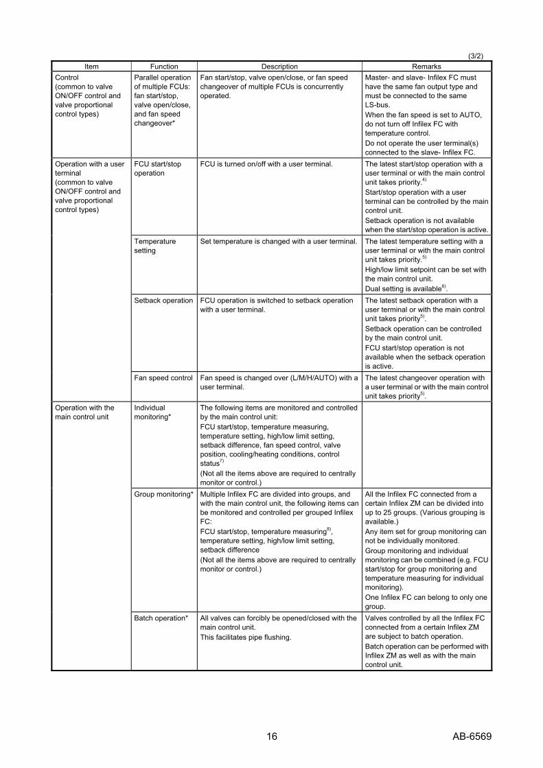
Control (common to valve ON/OFF control and valve proportional control types)
Parallel operation of multiple FCUs: fan start/stop, valve open/close, and fan speed changeover*
Fan start/stop, valve open/close, or fan speed changeover of multiple FCUs is concurrently operated.
Master- and slave- Infilex FC must have the same fan output type and must be connected to the same LS-bus. When the fan speed is set to AUTO, do not turn off Infilex FC with temperature control. Do not operate the user terminal(s) connected to the slave- Infilex FC.
FCU start/stop operation
FCU is turned on/off with a user terminal. The latest start/stop operation with a user terminal or with the main control unit takes priority.4) Start/stop operation with a user terminal can be controlled by the main control unit. Setback operation is not available when the start/stop operation is active.
Temperature setting
Set temperature is changed with a user terminal. The latest temperature setting with a user terminal or with the main control unit takes priority.5) High/low limit setpoint can be set with the main control unit. Dual setting is available6).
Setback operation FCU operation is switched to setback operation with a user terminal.
The latest setback operation with a user terminal or with the main control unit takes priority5). Setback operation can be controlled by the main control unit. FCU start/stop operation is not available when the setback operation is active.
Operation with a user terminal (common to valve ON/OFF control and valve proportional control types)
Fan speed control Fan speed is changed over (L/M/H/AUTO) with a user terminal.
The latest changeover operation with a user terminal or with the main control unit takes priority5).
Individual monitoring*
The following items are monitored and controlled by the main control unit: FCU start/stop, temperature measuring, temperature setting, high/low limit setting, setback difference, fan speed control, valve position, cooling/heating conditions, control status7) (Not all the items above are required to centrally monitor or control.)
Group monitoring* Multiple Infilex FC are divided into groups, and with the main control unit, the following items can be monitored and controlled per grouped Infilex FC: FCU start/stop, temperature measuring8), temperature setting, high/low limit setting, setback difference (Not all the items above are required to centrally monitor or control.)
All the Infilex FC connected from a certain Infilex ZM can be divided into up to 25 groups. (Various grouping is available.) Any item set for group monitoring can not be individually monitored. Group monitoring and individual monitoring can be combined (e.g. FCU start/stop for group monitoring and temperature measuring for individual monitoring). One Infilex FC can belong to only one group.
Operation with the main control unit
Batch operation* All valves can forcibly be opened/closed with the main control unit. This facilitates pipe flushing.
Valves controlled by all the Infilex FC connected from a certain Infilex ZM are subject to batch operation. Batch operation can be performed with Infilex ZM as well as with the main control unit.
17 AB-6569
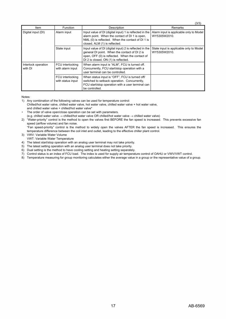
(3/3) Item Function Description Remarks
Alarm input Input value of DI (digital input) 1 is reflected in the alarm point. When the contact of DI 1 is open, NML (0) is reflected. When the contact of DI 1 is closed, ALM (1) is reflected.
Alarm input is applicable only to Model WY5305W2010.
Digital input (DI)
State input Input value of DI (digital input) 2 is reflected in the general DI point. When the contact of DI 2 is open, OFF (0) is reflected. When the contact of DI 2 is closed, ON (1) is reflected.
State input is applicable only to Model WY5305W2010.
FCU interlocking with alarm input
When alarm input is “ALM”, FCU is turned off. Concurrently, FCU start/stop operation with a user terminal can be controlled.
Interlock operation with DI
FCU interlocking with status input
When status input is “OFF”, FCU is turned off/ switched to setback operation. Concurrently, FCU start/stop operation with a user terminal can be controlled.
Notes: 1) Any combination of the following valves can be used for temperature control:
Chilled/hot water valve, chilled water valve, hot water valve, chilled water valve + hot water valve, and chilled water valve + chilled/hot water valve*
∗ The order of valve open/close operation can be set with parameters. (e.g. chilled water valve → chilled/hot water valve OR chilled/hot water valve → chilled water valve)
2) “Water-priority” control is the method to open the valves first BEFORE the fan speed is increased. This prevents excessive fan speed (airflow volume) and fan noise. “Fan speed-priority” control is the method to widely open the valves AFTER the fan speed is increased. This ensures the temperature difference between the coil inlet and outlet, leading to the effective chiller plant control.
3) VWV: Variable Water Volume VWT: Variable Water Temperature
4) The latest start/stop operation with an analog user terminal may not take priority. 5) The latest setting operation with an analog user terminal does not take priority. 6) Dual setting is the method to have cooling setting and heating setting separately. 7) Control status is an index of FCU load. The index is used for supply air temperature control of OAHU or VWV/VWT control. 8) Temperature measuring for group monitoring calculates either the average value in a group or the representative value of a group.

18 AB-6569
Setting The following settings must be performed by a technical engineer.
1. LED indication (See Figs 33 to 35.) After the power is applied to Infilex FC, check that the status indicator LED (red) blinks in approx. 10 seconds. If it stays ON, Infilex FC is in abnormal status. Note that the LED (red) stays ON immediately after the power is applied to Infilex FC, which does not indicate error.
Communication (with LonTalk protocol) LED (green) instantly flashes when the power is applied. Then, the LED is off when LonTalk communication is normal.
For the description of LED indications, refer to Figs. 34 and 35. (LED indication is described on the parts identification label attached to the front surface of Infilex FC as shown in Fig. 33.)
Valve ON/OFF control type
Valve proportional control type
Figure 33. LED indication
Status LED indication (□: ON / ■: OFF)
Normal Normal
Power OFF Power Off
LS-bus error LS-bus Err
Initializing / Error
Error 1
Minor error Error 2
Figure 34. Descriptions of red LED indication (status)
Status LED indication (□: ON / ■: OFF)
Normal Normal
Applicationless Appli-less
Unconfigured Unconfig
LS-bus error Any indication other than the above. Figure 35. Descriptions of green LED indication
(Communication with LonTalk protocol)
2. Address setting (See Fig. 33) Two address setting dials are located on the front surface of Infilex FC. The allow of the upper dial (with ‘X10’) indicates tens, and the allow of the lower dial (with ‘X1') indicates ones. For setting the address, use a small Philips screw driver to turn the dial.
3. Parameter setting
Infilex FC parameters are set in response to the size and type of FCU, room characteristics, and applications.
To Connect Two User Terminals (for Remote Control) Up to two digital user terminals (Neopanel Model QY7205C) can be connected to one Infilex FC.
To connect the two user terminals,
• Modular branch unit (Model DY7203A0000)
• Neopanel with address 1 and with address 2.
(Note that two Neopanel with address 1 connected to the Infilex FC do not work.)
are required.
Address number is indicated on the shipping carton and on the label attached to the inside surface of the Neopanel main unit (with the base cover removed). Notes: ∗ The latest FCU start/stop operation or temperature setting
operation with a Neopanel or with the main control unit takes priority.
∗ Neopanel with address 2 does not have a temperature measuring function.
1s 1s
0.25s 0.25s
1s 0.25s
0.25s 0.25s
3s
1s 1s
LED (red)LED (red)
Descriptions of LED indication
Address setting dial
Address setting dial
LED (green)
LED(green)

19 AB-6569
Connection of Data Setter for LonTalk Protocol Connect the CompactFlash® memory type Data Setter (Model QY5111B) for LonTalk protocol to LS-bus port of Infilex FC with the Data Setter adaptor (Part No. DY5301S0000, with separate order required). For details of the Data Setter adaptor, refer to its Specifications manual. LS-bus (LonTalk protocol) (For setting Infilex FC and the remote units connected on LS-bus: Connect Data Setter with Data Setter adaptor to LS-bus port of Infilex FC.) Note:
Parameters of a remote unit on LS-bus (sub-controller) can also be set and modified with the Data Setter with Data Setter adaptor connected on a remote unit on LC-bus (controller). Refer to Specifications/Instructions of the respective controllers.
Figure 36. Connection example of Data Setter with Data setter adaptor to LS-bus port of Infilex FC
Infilex FCModel WY5305
IAC Model WY7307
Infilex VC Model WY5306
Data Setter adaptor
Model DY5301S
Data Setter Model QY5111B
20 AB-6569
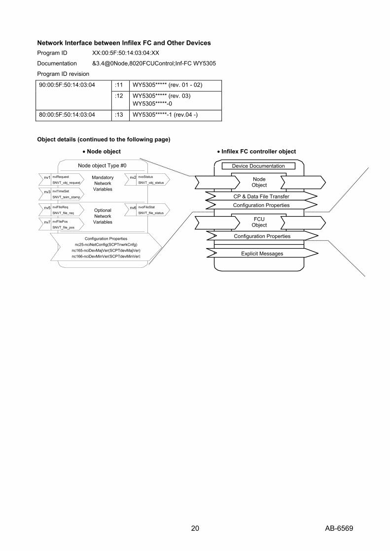
Network Interface between Infilex FC and Other Devices Program ID XX:00:5F:50:14:03:04:XX
Documentation &3.4@0Node,8020FCUControl;Inf-FC WY5305
Program ID revision
:11 WY5305***** (rev. 01 - 02) 90:00:5F:50:14:03:04
:12 WY5305***** (rev. 03) WY5305*****-0
80:00:5F:50:14:03:04 :13 WY5305*****-1 (rev.04 -)
Object details (continued to the following page)
• Node object • Infilex FC controller object
Configuration Properties nc25-nciNetConfig(SCPTnwrkCnfg)
nc165-nciDevMajVer(SCPTdevMajVer) nc166-nciDevMinVer(SCPTdevMinVer)
Optional Network Variables
Node object Type #0
Mandatory Network Variables
nviRequest
SNVT_obj_request nv1
nviTimeSet
SNVT_teim_stamp nv3
nviFIleReq
SNVT_file_req nv5
nviFilePos
SNVT_file_pos nv7
nvoStatus
SNVT_obj_statusnv2
nvoFileStat
SNVT_file_statusnv6
Explicit Messages
FCU Object
Device Documentation
Node Object
Configuration Properties
CP & Data File Transfer Configuration Properties
21 AB-6569
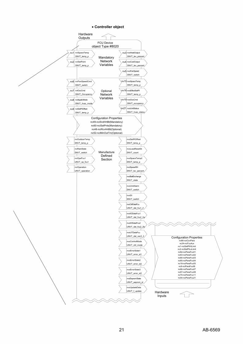
• Controller object
nviOutdoorTemp
SNVT_temp_p
nviRainState
SNVT_switch
nviOpeFcu1
UNVT_op_fcu1 nviOperation
UNVT_operation
nvoSetPtOffset
SNVT_temp_p
nvoLoadResetSt
SNVT_count
nvoSpaceTemp2
SNVT_temp_p
nvoSpaceRH
SNVT_lev_percent
nvoBattExchange
SNVT_state
nvoUnitAlarm
SNVT_switch
nvoDI
SNVT_switch nvoCtrlDataFcu
UNVT_dat_fcu1_2
nvoIODataFcu1
UNVT_dat_fcu2_2a
nvoIODataFcu2
UNVT_dat_fcu2_2b
nvoUTDataFcu
UNVT_dat_vav3_2 nvoControlMode UNVT_ctrl_mode
nvoErrorState1
UNVT_error_st1
nvoErrorState2
UNVT_error_st2
nvoErrorState3
UNVT_error_st2 nvoEepromState
UNVT_eeprom_st nvoUpdateData
UNVT_f_update
nviSpaceTemp
SNVT_temp_p nv1
nviSetPoint
SNVT_temp_p nv2
nviFanSpeedCmd
SNVT_switch nv6
nviOccCmd
SNVT_Occupancy nv7
nviApplicMode
SNVT_hvac_mode nv8
nviSetPtOffset
SNVT_temp_p nv9
nvoFanSpeed
SNVT_switch nv5
nvoSpaceTemp
SNVT_temp_p
nv15
nvoEffectSetPt
SNVT_temp_p nv16
nvoOccCmd
SNVT_occupancy nv19
nvoHeatOutput
SNVT_lev_precent nv3
nvoCoolOutput
SNVT_lev_percent nv4
nvoUnitStatus
SNVT_hvac_status nv21
Configuration Properties nc49-nciSndHrtBt(Mandatory) nc60-nciSetPnts(Mandatory) nc48-nciRcvHrtBt(Optional)
nc52-nciMinOutTm(Optional)
Hardware Outputs
FCU Device object Type #8020
ManufactureDefined Section
Hardware Inputs
Mandatory Network Variables
Optional Network Variables
Configuration Propertiesnc68-nciCovPara nc24-nciFcuAux
nc1-nciSetPtHiLimit nc2-nciSetPtLoLimit nc62-nciParaFcu01 nc63-nciParaFcu02 nc64-nciParaFcu03 nc65-nciParaFcu04 nc18-nciParaFcu05 nc8-nciParaFcu06 nc66-nciParaFcu07 nc67-nciParaFcu08 nc70-nciParaFcu11 nc54-nciParaFcu21
22 AB-6569
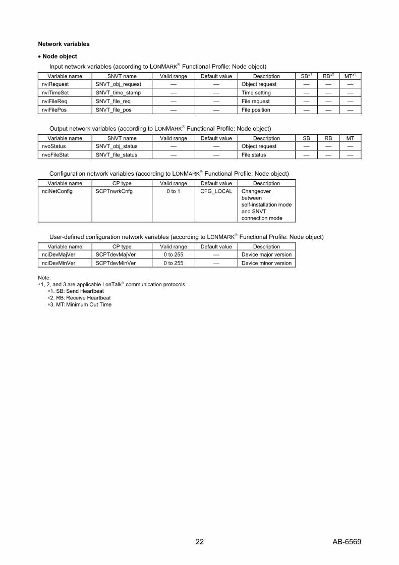
Network variables
• Node object Input network variables (according to LONMARK® Functional Profile: Node object)
Variable name SNVT name Valid range Default value Description SB*1 RB*2 MT*3
nviRequest SNVT_obj_request ⎯ ⎯ Object request ⎯ ⎯ ⎯ nviTimeSet SNVT_time_stamp ⎯ ⎯ Time setting ⎯ ⎯ ⎯ nviFileReq SNVT_file_req ⎯ ⎯ File request ⎯ ⎯ ⎯ nviFilePos SNVT_file_pos ⎯ ⎯ File position ⎯ ⎯ ⎯
Output network variables (according to LONMARK® Functional Profile: Node object) Variable name SNVT name Valid range Default value Description SB RB MT
nvoStatus SNVT_obj_status ⎯ ⎯ Object request ⎯ ⎯ ⎯ nvoFileStat SNVT_file_status ⎯ ⎯ File status ⎯ ⎯ ⎯
Configuration network variables (according to LONMARK® Functional Profile: Node object) Variable name CP type Valid range Default value Description
nciNetConfig SCPTnwrkCnfg 0 to 1 CFG_LOCAL Changeover between self-installation mode and SNVT connection mode
User-defined configuration network variables (according to LONMARK® Functional Profile: Node object) Variable name CP type Valid range Default value Description
nciDevMajVer SCPTdevMajVer 0 to 255 ⎯ Device major version nciDevMinVer SCPTdevMinVer 0 to 255 ⎯ Device minor version
Note: ∗1, 2, and 3 are applicable LonTalk® communication protocols.
∗1. SB: Send Heartbeat ∗2. RB: Receive Heartbeat ∗3. MT: Minimum Out Time
23 AB-6569
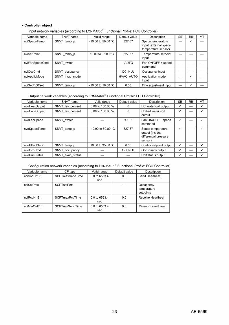
• Controller object Input network variables (according to LONMARK® Functional Profile: FCU Controller)
Variable name SNVT name Valid range Default value Description SB RB MTnviSpaceTemp SNVT_temp_p -10.00 to 50.00 °C 327.67 Space temperature
input (external space temperature sensor)
⎯ ⎯
nviSetPoint SNVT_temp_p 10.00 to 35.00 °C 327.67 Temperature setpoint input
⎯ ⎯ ⎯
nviFanSpeedCmd SNVT_switch ⎯ “AUTO Fan ON/OFF + speed command
⎯ ⎯ ⎯
nviOccCmd SNVT_occupancy ⎯ OC_NUL Occupancy input ⎯ ⎯ ⎯ nviApplicMode SNVT_hvac_mode ⎯ HVAC_AUTO Application mode
input ⎯ ⎯
nviSetPtOffset SNVT_temp_p -10.00 to 10.00 °C 0.00 Fine adjustment input ⎯ ⎯
Output network variables (according to LONMARK® Functional Profile: FCU Controller) Variable name SNVT name Valid range Default value Description SB RB MT
nvoHeatOutput SNVT_lev_percent 0.00 to 100.00 % 0 Hot water coil output ⎯ nvoCoolOutput SNVT_lev_percent 0.00 to 100.00 % 0 Chilled water coil
output ⎯
nvoFanSpeed SNVT_switch ⎯ “OFF” Fan ON/OFF + speed command
⎯
nvoSpaceTemp SNVT_temp_p -10.00 to 50.00 °C 327.67 Space temperature output (inside: differential pressure sensor)
⎯
nvoEffectSetPt SNVT_temp_p 10.00 to 35.00 °C 0.00 Control setpoint output ⎯ nvoOccCmd SNVT_occupancy ⎯ OC_NUL Occupancy output ⎯ nvoUnitStatus SNVT_hvac_status ⎯ ⎯ Unit status output ⎯
Configuration network variables (according to LONMARK® Functional Profile: FCU Controller) Variable name CP type Valid range Default value Description
nciSndHrtBt SCPTmaxSendTime 0.0 to 6553.4 sec
0.0 Send Heartbeat
nciSetPnts SCPTsetPnts ⎯ ⎯ Occupancy temperature setpoints
nciRcvHrtBt SCPTmaxRcvTime 0.0 to 6553.4 sec
0.0 Receive Heartbeat
nciMinOutTm SCPTminSendTime 0.0 to 6553.4 sec
0.0 Minimum send time
24 AB-6569
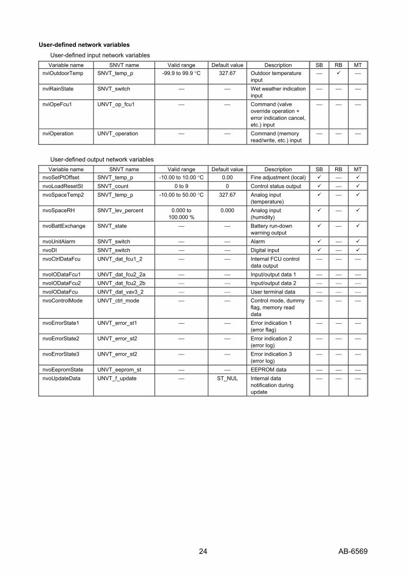
User-defined network variables User-defined input network variables
Variable name SNVT name Valid range Default value Description SB RB MTnviOutdoorTemp SNVT_temp_p -99.9 to 99.9 °C 327.67 Outdoor temperature
input ⎯ ⎯
nviRainState SNVT_switch ⎯ ⎯ Wet weather indication input
⎯ ⎯ ⎯
nviOpeFcu1 UNVT_op_fcu1 ⎯ ⎯ Command (valve override operation + error indication cancel, etc.) input
⎯ ⎯ ⎯
nviOperation UNVT_operation ⎯ ⎯ Command (memory read/write, etc.) input
⎯ ⎯ ⎯
User-defined output network variables Variable name SNVT name Valid range Default value Description SB RB MT
nvoSetPtOffset SNVT_temp_p -10.00 to 10.00 °C 0.00 Fine adjustment (local) ⎯ nvoLoadResetSt SNVT_count 0 to 9 0 Control status output ⎯ nvoSpaceTemp2 SNVT_temp_p -10.00 to 50.00 °C 327.67 Analog input
(temperature) ⎯
nvoSpaceRH SNVT_lev_percent 0.000 to 100.000 %
0.000 Analog input (humidity)
⎯
nvoBattExchange SNVT_state ⎯ ⎯ Battery run-down warning output
⎯
nvoUnitAlarm SNVT_switch ⎯ ⎯ Alarm ⎯ nvoDI SNVT_switch ⎯ ⎯ Digital input ⎯ nvoCtrlDataFcu UNVT_dat_fcu1_2 ⎯ ⎯ Internal FCU control
data output ⎯ ⎯ ⎯
nvoIODataFcu1 UNVT_dat_fcu2_2a ⎯ ⎯ Input/output data 1 ⎯ ⎯ ⎯ nvoIODataFcu2 UNVT_dat_fcu2_2b ⎯ ⎯ Input/output data 2 ⎯ ⎯ ⎯ nvoIODataFcu UNVT_dat_vav3_2 ⎯ ⎯ User terminal data ⎯ ⎯ ⎯ nvoControlMode UNVT_ctrl_mode ⎯ ⎯ Control mode, dummy
flag, memory read data
⎯ ⎯ ⎯
nvoErrorState1 UNVT_error_st1 ⎯ ⎯ Error indication 1 (error flag)
⎯ ⎯ ⎯
nvoErrorState2 UNVT_error_st2 ⎯ ⎯ Error indication 2 (error log)
⎯ ⎯ ⎯
nvoErrorState3 UNVT_error_st2 ⎯ ⎯ Error indication 3 (error log)
⎯ ⎯ ⎯
nvoEepromState UNVT_eeprom_st ⎯ ⎯ EEPROM data ⎯ ⎯ ⎯ nvoUpdateData UNVT_f_update ⎯ ST_NUL Internal data
notification during update
⎯ ⎯ ⎯

25 AB-6569
User-defined configuration network variables Variable name CP type Valid range Default
valueDescription
nciCovPara UCPTfcuMinDelta2 (Resource file)
⎯ ⎯ Load reset type + COV value
nciFcuAux UCPTfcuAux ⎯ ⎯ Auxiliary parameter
User-defined parameters Variable name CP type Valid range Default value Description
nciSetPtHiLimit UCPTsetPointHighLimit 0.00 to 50.00 °C
30.00 Setpoint high limit
nciSetPtLoLimit UCPTsetPointLowLimit 0.00 to 50.00 °C
15.00 Setpoint low limit
nciParaFcu01 UCPTfcuCtrlType2 ⎯ ⎯ Operation control parameter
nciParaFcu02 UCPTfcuTempCtrl2 ⎯ ⎯ Temperature control parameter
nciParaFcu03 UCPTfcuDischargeAirTempCtrl2 ⎯ ⎯ Duct inlet temperature optimization parameter
nciParaFcu04 UCPTfcuUnitType2 ⎯ ⎯ FCU parameter nciParaFcu05 UCPTfcuFanCtrl ⎯ ⎯ Fan speed automatic
control parameter nciParaFcu06 UCPTctrlDisable ⎯ ⎯ Assign/delete point
parameter, assign/delete control parameter
nciParaFcu07 UCPTfcuAI_Adjustment2 ⎯ ⎯ Input/output adjustment parameter
nciParaFcu08 UCPTfcuManufAdjustment2 ⎯ ⎯ Manufacturer adjusted parameter
nciParaFcu11 UCPTfcuMiscellaneous2 ⎯ ⎯ Basic parameter nciParaFcu21 UCPTsetPointKnob2 ⎯ ⎯ AI processing table


Specifications are subject to change without notice.
Building Systems Company http://www.yamatake.com Rev. 2.0 May 2006 AB-6569 0.2H-H (W03)(J: AI-6569 Rev. 2.0) Printed in Japan.