INEXPENSIVE WIRELESS TELEMETRY FOR ANIMAL...
27
INEXPENSIVE WIRELESS TELEMETRY FOR ANIMAL TRACKING A Design Project Report Presented to the Engineering Division of the Graduate School Of Cornell University In Partial Fulfillment of the Requirements for the Degree of Master of Engineering (Electrical) By Christopher Yeou-Hwa Chau Project Advisor: Bruce Land Degree Date: May 2003
Transcript of INEXPENSIVE WIRELESS TELEMETRY FOR ANIMAL...

INEXPENSIVE WIRELESS TELEMETRY FORANIMAL TRACKING
A Design Project Report
Presented to the Engineering Division of the Graduate School
Of Cornell University
In Partial Fulfillment of the Requirements for the Degree of
Master of Engineering (Electrical)
By
Christopher Yeou-Hwa Chau
Project Advisor: Bruce Land
Degree Date: May 2003

Abstract
Master of Electrical Engineering Program
Cornell University
Design Project Report
Project Title: Inexpensive Wireless Telemetry for Animal Tracking
Author: Christopher Yeou-Hwa Chau
Abstract: This project explored the feasibility of creating a cost-effective transmitter-receiver pair to replace commercially available 150 MHz devices used in animaltelemetry. Distance measurements of test circuits transmitting at 418 MHz were takenover clear ground and in forested areas to demonstrate that 400 MHz radiation is capableof acceptable forest penetration. A transmitter was then designed and optimized forpower consumption and cost. The final transmitter has a total current draw of 70 uA.Components for the transmitter-receiver pair are available at considerably less cost thancommercial devices.
Report Approved by
Project Advisor: ________________________Date: ___________________

Executive Summary
This project explored the feasibility of creating a cost-effective transmitter-
receiver pair to replace commercially available 150 MHz devices used in animal
telemetry. Distance measurements of test circuits transmitting at 418 MHz were taken
over clear ground and in forested areas. These measurements show a range of 300-400
feet in forest underbrush and acceptable dropoff over distance, demonstrating that 70 cm
radiation can be used in this application. For testing, a 418 MHz Yagi antenna was
constructed and shown to exhibit strong directionality and approximately 20 dB gain in
the forward direction.
Once it was determined that 400 MHz radiation is capable of forest penetration to
the range specified, the transmitter design was optimized for greater battery life. After
exploring several potential oscillator designs for transmitter input, an op-amp circuit was
designed with appropriate PCB layout. A 433 MHz transmitter/receiver pair was
constructed and tested to show signal range at the same level as earlier measurements at
significantly lower power consumption rate. The final transmitter has a total current draw
of 70 uA. This translates to roughly one and a half months of continuous operation using
freely available 70 mAh lithium-ion coin batteries. Components for the transmitter-
receiver pair are available at considerably less cost than commercial devices, with
component cost for each transmitter at roughly ten dollars and for the receiver at less than
twenty dollars.

Design Problem & System of Requirements
Field biologists are often required to track animals for research purposes. In order
to do so, wireless transmitters are attached to wildlife and re-released into their native
environment. Over a period of days or weeks the field biologist then uses a receiver to
identify the location of radio-tagged animals after they have been released. Because the
goal is to observe animals with as little disturbance to them as possible, the transmitters
need to be optimized for size and weight depending on the animal.
However, the transmitters also need to be somewhat rugged to survive the
outdoors, and battery life must be reasonably long so that recapture of animals for
replacement of batteries is unnecessary. In addition, the transmitter must be detectable
through forest terrain from a significant distance. Depending on the particular
application, the receiver must also be relatively mobile, such that it can be carried easily.
Commercially available transmitter-receiver pairs designed for tracking animals
typically use 150 MHz radiation, which has a wavelength of approximately two meters.
They are fairly expensive, at around $100 each, and the two-meter radiation requires an
extremely bulky receiving station and a relatively long transmitter antenna. The intent of
this project is to build a prototype transmitter-receiver pair which is less costly and more
convenient as a result of using smaller wavelength radiation, while sacrificing as little as
possible in size, weight, and receiving distance.
A clear set of design goals can be set for both the transmitter (to be placed on the
animal) and the receiver (carried by the biologist). The transmitter should be as small and
lightweight as possible with off-the-shelf components. The battery lifetime probably
needs several days of continuous operation, at the bare minimum. Finally, the transmitted

signal must be detectible through forest or underbrush for a minimum of 100 meters, with
1 kilometer of penetration optimal. In addition, the total cost of parts for each transmitter
should be less than $50. The receiver, of course, does not need to be as small as the
transmitter. It must, however, be relatively portable (weighing less than ten pounds), and
it should likewise be relatively inexpensive.
While a more complex signal might be used later, the goal of the current design
was to transmit a simple audio tone. The field biologist can then listen to the output of the
receiver in conjunction with the directional antenna receiver to track the location of the
transmitter.
Range of Solutions available
Many tradeoffs need to be considered and are inherent to the design of the
transmitter. The choice of which wavelength radiation is important, because shorter
wavelength radiation results in a shorter antenna, but possibly decreases range of
transmission through forest terrain. The current use of two-meter radiation results in
transmission and receiving antennas which are overly large. This project focused on
transmitter/receiver pairs in the 400 MHz range, as many modules are available at 418
and 433 MHz, while available 900 MHz devices were less likely to transmit to the
distance required for this application.
Off-the-shelf components for the transmitter and receiver were selected due to
cost efficacy, as the transmitter/receiver pairs will only be produced in fairly small
volumes (< 5-10 transmitters per year). The simplicity of the system and cost factors
allow the use of a relatively simple transmitter, with either AM or FM functionality.

Because weight and length of usage are both important factors, the choice of
power supply was critical. Any power source larger than lithium coin-sized batteries are
too heavy for this application. Lithium coin batteries are also quite inexpensive, widely
available, and of high energy density. The use of coin batteries requires all components to
operate at 3V, for which there are a few OTS transmitters available.
For the antenna on the transmitter, there are only a few practical possibilities. The
antenna cannot be too complex, in order to create as little inconvenience as possible for
the animal being tracked. In addition, the broadcast transmitter should be
omnidirectional. This excludes the use of yagi or a dish being attached to the transmitter.
Quarter-wave antennas are commonly used on many currently available devices.
Whip antennas encased in a protective material are frequently used in commercial
designs. An interesting alternative made possible by the use of smaller-wavelength
radiation is a PCB-based antenna. By routing the antenna onto a circuit board instead of
using an external antenna, it becomes significantly less obtrusive to the tracked animal
and increases the physical durability of the transmitter. This was not used in the current
implementation, but could be a future improvement on the current design.
The waveform being transmitted needs to be an audible tone, ideally in the 1-5
kHz range. To conserve power, the tone need not be constantly on, but instead could send
a pulsed audio signal approximately once a second. The circuit generating the signal for
transmission should then consist of two oscillators, the first with a duty cycle of
approximately 1-2% operating at 1 Hz, which then controls a second oscillator with a
50% duty cycle operating somewhere between one and five kHz.

The circuit required for the transmitter itself necessitates an oscillator input to the
RF chip. The easiest way to do this is with a 555 timer chip, a standard IC composed of
two internally wired op-amps and only requiring an external resistor and capacitor to
generate the time constant defining frequency of oscillation (figure 10). Duty cycle for
these chips were also easily configured with appropriate resistor value inputs. Because of
the ease of setup, 555 timer chips were initially used in testing the range of the
transmitter/receiver setup. However, the op-amps used in the 555 timer chip were not
optimized for low-power consumption, and used bipolar junction transistors. As a result,
they drew too much current to be considered for the final design.
In an attempt to reduce current draw, a set of NAND gates connected in an RC
circuit were considered as an alternative to the use of the 555 timer chip (figure 9). As
with the previous setup, duty cycles could be configured using appropriate resistor
values. It was initially thought that CMOS, by its operation, would present a low-power
solution because of its effectively zero current draw at steady-state. In practice, however,
the set of NAND gates did not conserve much power because of the frequent, long
transitions between high and low states in an RC oscillator circuit.
Instead of using a pre-built op-amp oscillator such as the 555 timer chip, it is
possible to construct an op-amp oscillator made of discrete resistors and a set of low-
power op-amps. Selection of appropriate op-amps was based on current draw and speed
requirements (linear bandwidth and skew rate limitations).
The receiver design has fewer constraints. A Yagi antenna design was used for
relatively high directional gain at extremely low cost (Figure 2). The antenna design was
from a publicly available website. (http://www.tfs.net/~petek/rockets/RDF/70ant.html)

Documentation of design and implementation
The power supply for the receiver is not as weight-limited as the transmitter. As
such, a 5V power supply was constructed from a simple circuit using a 9V battery. This
represents a significant improvement over many currently available receivers in this
application, which are typically 6 D-cell batteries weighing approximately one pound.
AM and FM transmitter and receiver test designs were constructed which used
lithium coin batteries. Quarter-wave whip antennas were used for both transmitters. The
receiver uses a six-element yagi antenna designed for 400 MHz reception. A balun
transformer as shown converts the signal as necessary for input to the receiver module.
This antenna was used for making range measurements.
The IC used in the transmitter design is the MAX4471, from Maxim IC, which
contains two op-amps in a single package. The physical implementation of the transmitter
was possible using a small PCB with all circuit components excepting the battery
surface-mounted to the board.
All of the oscillators depend on RC time constants generated by a resistor-
capacitor pair. However, the preference for an extremely short duty cycle on the first
oscillator introduced some difficulty, as the op-amp oscillator circuit (see Figure 11) was
not capable of generating such an oscillation pattern. Instead, the output of a 50% duty
cycle 1 Hz oscillator is connected to a simple edge detector circuit, with the width of the
edged detection pulses determined by a second RC constant. Because the edge detector
produces both a positive and negative pulse, a Schottky diode with the cathode facing

ground is in parallel with the resistor in the RC constant. This diode limits the negative
pulse on the downward edge to -0.3V.
Once the two oscillators worked individually, it was discovered that the two
oscillators interacted with each other in an undesirable fashion when connected together.
The diode in between the two reduces the small voltage from the second oscillator which
was affecting the behavior of the first. Similarly, the diode and resistor in between the
second oscillator and the transmitter are also to produce a cleaner input signal to the
transmitter.
After making these modifications to the circuit, using the first 1 Hz oscillator to
modulate oscillation of the second oscillator proved unworkable while building the
prototype. While this circuit worked correctly on the breadboard, both oscillators failed to
function correctly when parts were placed onto the PCB. In the course of debugging this
design, the circuit demonstrated extreme capacitance sensitivity, in that unconnected
metal wires touched to various points could affect circuit behavior. Consequently, the
method of gating between the two oscillators was modified and a slightly different circuit
was used (Figure 12).
The final design submitted relies on each op-amp oscillator circuit to sink current
from the voltage source and a resistor load. The battery is connected through a resistor to
a single node with three other connections- two diodes, each with the anode terminal
facing the output of one oscillator circuit, and the signal input to the RF transmitter chip.
When an oscillator output is high, the oscillator circuit is disconnected from the signal
input because of the diode in series. If either oscillator is low, the voltage from the battery
and resistor in series is sunk into the op-amp. The resistor in series can be used to trade

off battery lifetime versus signal strength- a higher resistance lowers signal strength but
also reduces current through the circuit, hence increasing battery lifetime.
This circuit eliminates several potential issues that may have affected behavior of
the previous circuit, such as interaction between the two oscillators and the possibility of
the op-amps being unable to source enough current to pull the signal input high. The final
circuit design, shown here, is also reproduced in the appendix as Figure 12.
An oscilloscope trace for the signal input to the signal input of the transmitter chip
is provided. (The rectangular object in the picture is the reflection of the camera on the
front of the oscilloscope.) The nonzero resting value of the circuit is acceptable because
the AM transmitter expects a CMOS input. Consequently, the transmitter is not keyed on
by the low voltage. Once per second, the oscillator circuits sends a short high pulse which
oscillates at 2 kHz. A short pulse is just long enough to be audible at the receiver.

With approximately four cycles above 1V, the transmitted 2 kHz pulse is
approximately 2 milliseconds long and hence a 2% duty cycle for the transmitter. A
second trace verifies that the pulse is extremely short over the total cycle of the oscillator
outputs.

Schematics are provided for all circuits in the Appendix. PCB layouts are also
illustrated for the two op-amp oscillator circuits. Specific IC’s used in the field-tested
prototypes were the Abacom AM-TX1-418 transmitter and AM-RRS2-418 receiver for
the AM distance values. The Radiometrix TXM-418-A transmitter and RXM-418-A
receiver were used in determining FM transmission characteristics.
The final transmitter device with op-amp oscillator circuits used the Radiotronix
RCT-433-AS AM transmitter and the Maxim MAX407-ESA dual op-amp package. The
receiver used the Radiotronix RCR-433-HP. Components for the transmitter-receiver pair
used in the final design are available at considerably less cost than commercial tracking
devices, with component cost for each transmitter at roughly ten dollars and for the
receiver at less than twenty dollars.
System test results
Distance measurements were initially made on the original prototypes
constructed, for both AM and FM versions. Most measurements were made on the FM
receiver because of a signal strength indicator built into the FM receiver, which was
notably lacking on the AM module. RSSI (Received Signal Strength Indicator) values
vary from 0 to 3.3 V, and increase logarithmically with signal strength. Values were read
out from the device using a digital voltmeter. Before measuring, the noise threshold of
the RSSI value was determined to be 0.076. This value was consistently obtained even if
the transmitter was not turned on. Consequently, any values measured at or below this
value are omitted from graphs and linear regression, but are included in the data appendix
for completeness.

Chart 1 - FM RSSI, no antenna, clear ground
0
0.5
1
1.5
2
2.5
3
3.5
0.7 0.9 1.1 1.3 1.5 1.7 1.9 2.1 2.3
log (distance in feet)
RS
SI Trial 1
Trial 2
Trial 3
Chart 1 shows the measurement of RSSI on a flat grassy area. The transmitter was
placed one foot above the ground, without the quarter wave antenna. Trial 1 was taken on
a separate day from trials 2 and 3. The slope for each line, obtained by linear regression,
are -2.66, -3.37, and -2.99, respectively. The low values for Trial 2 can be attributed to
low battery power, as the transmitter battery failed and had to be replaced shortly after
data was taken for Trial 2. The similarity of slope values for Trials 1 and 3 indicate some
reproduceability in RSSI measurements. Trial 2 values also demonstrate that, while range
is significantly reduced by low battery power, the transmitter will at least still function
well enough to produce a measurable signal.

Chart 2 - FM RSSI, with antenna, in forest, ground level
0
0.5
1
1.5
2
2.5
3
3.5
1 1.2 1.4 1.6 1.8 2 2.2 2.4 2.6 2.8
natural log (distance in feet)
RS
SI
Because the ultimate application of the project is in a forested area, it was
important to measure the range of the signal in an area where trees could affect the
transmission distance. RSSI in Chart 2 was measured in a forested area near Ithaca with a
significant levels of underbrush present. The transmitter was placed on the ground, and
the receiver antenna was held roughly 2-3 feet off the ground. Distance measures are
approximate. Linear regression provides a slope at -2.51, similar to the rate of dropoff
with distance than observed on unobstructed ground.
95% confidence interval 95% confidence interval
regression slope (lower bound) (upper bound)
Chart 1, Trial 1 -2.661123726 -1.669782682 -3.652464769
Chart 1, Trial 2 -3.366382058 -2.477987702 -4.254776415
Chart 1, Trial 3 -2.991475887 -2.43625003 -3.546701745
Chart 2 -2.506214963 -0.980192165 -4.03223776
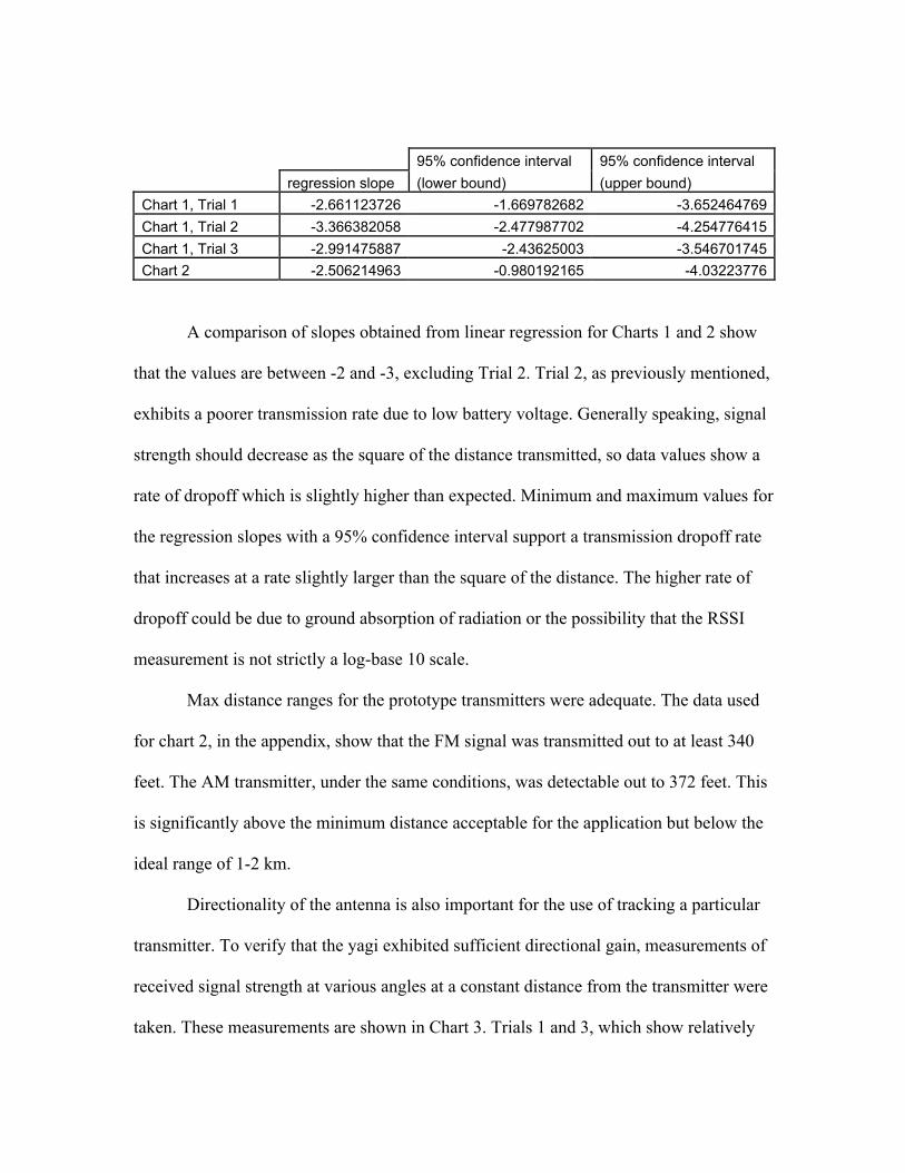
A comparison of slopes obtained from linear regression for Charts 1 and 2 show
that the values are between -2 and -3, excluding Trial 2. Trial 2, as previously mentioned,
exhibits a poorer transmission rate due to low battery voltage. Generally speaking, signal
strength should decrease as the square of the distance transmitted, so data values show a
rate of dropoff which is slightly higher than expected. Minimum and maximum values for
the regression slopes with a 95% confidence interval support a transmission dropoff rate
that increases at a rate slightly larger than the square of the distance. The higher rate of
dropoff could be due to ground absorption of radiation or the possibility that the RSSI
measurement is not strictly a log-base 10 scale.
Max distance ranges for the prototype transmitters were adequate. The data used
for chart 2, in the appendix, show that the FM signal was transmitted out to at least 340
feet. The AM transmitter, under the same conditions, was detectable out to 372 feet. This
is significantly above the minimum distance acceptable for the application but below the
ideal range of 1-2 km.
Directionality of the antenna is also important for the use of tracking a particular
transmitter. To verify that the yagi exhibited sufficient directional gain, measurements of
received signal strength at various angles at a constant distance from the transmitter were
taken. These measurements are shown in Chart 3. Trials 1 and 3, which show relatively

little variance of RSSI with angle, were taken at a relatively close distance from the
transmitter, and show that directionality is not clearly evident at lower distances, likely a
result of multi-path effects. Trial 2 more clearly shows an appropriate dropoff of signal
strength with angle. The forward gain of approximately 20 dB is an acceptable value for
the Yagi antenna used. Obviously, higher gain may be possible using a more finely tuned
antenna design or the use of additional elements in the Yagi.
Chart 3 -RSSI variance with antenna angle
0
0.5
1
1.5
2
2.5
3
3.5
0 20 40 60 80 100
angle
RS
SI Trial 1
Trial 2
Trial 3
The data graphed in Charts 1-3 were made using the NAND oscillator circuit at
418 megahertz, but the final design for the op-amp oscillator circuits used a different
transmitter at 433 megahertz. Using a whip antenna attached to the receiver, the final
design for the op-amp circuit and transmitter was audible approximately 100 feet from
the receiver. Using the 418-MHz tuned yagi, this transmitter signal was detected out to
200 feet. These simple measurements indicate a range on par with the earlier

measurements, as a yagi tuned to the correct frequency should produce a higher gain. The
revised op-amp circuit as shown draws 70 uA. Using a standard lithium coin battery this
should result in continuous operation for roughly a month and a half before the power
supply would be exhausted. However, this can be tuned as described earlier, with a
tradeoff between signal strength and power usage dependent on the value of the resistor
in series with the voltage source.
In conclusion, the tracking/receiving pair which has been constructed is a good
first step towards development of a system which is considerably cheaper than
commercial modules which are currently available, with an acceptable tradeoff in signal
detection range and battery lifetime for the desired application. As mentioned previously,
a single resistor in the design can be used in the future to exchange signal strength for
battery lifetime. Further improvements to signal detection might also obtained by using a
more finely tuned receiver antenna or adding noise reduction to the receiver system input.

Appendix
The 5V power supply shown in Figure 1 was used in both AM and FM receivers
as well as the final receiver design. The Yagi in Figure 2 was used for all signal
measurements where noted. Figures 3, 4, 5, and 6 pertain to transmitter/receiver pairs
which were used for collecting data shown in Charts 1-3, but are not pertinent to the final
transmitter/receiver pair design. Figures 7 and 8 relate to component parts which are used
in the final design, whereas Figures 9-11 represent circuits which were initial candidates
for the oscillator design that ultimately failed. Figure 12 shows the circuit which was
used in the final design. Figures 13 and 14 show PCB layouts which were made during
this project, with the latter being a slight revision of the former. The PCB shown in
Figure 14 was used and tested as the final transmitter design.
Figure 1: Schematic of 5V supply from 9V battery

Figure 2: Yagi antenna design
Figure 3: Field-tested 418 MHz AM transmitter

Figure 4: Pinout of IC for field-tested 418 MHz AM receiver
Figure 5: Field-tested 418 MHz FM transmitter

Figure 6: Field-tested 418 MHz FM receiver
Figure 7: Pinout of IC for final 433 MHz AM transmitter

Figure 8: Pinout of IC for final 433 MHz AM receiver
Figure 9: Schematic of NAND-based oscillator

Figure 10: Schematic of 555-timer-based oscillator

Figure 11: Schematic of first op-amp-based oscillator circuit
Figure 12: Schematic of final op-amp oscillator circuit

Figure 13: PCB layout for first op-amp oscillator circuit
Figure 14: PCB layout for second op-amp oscillator circuit
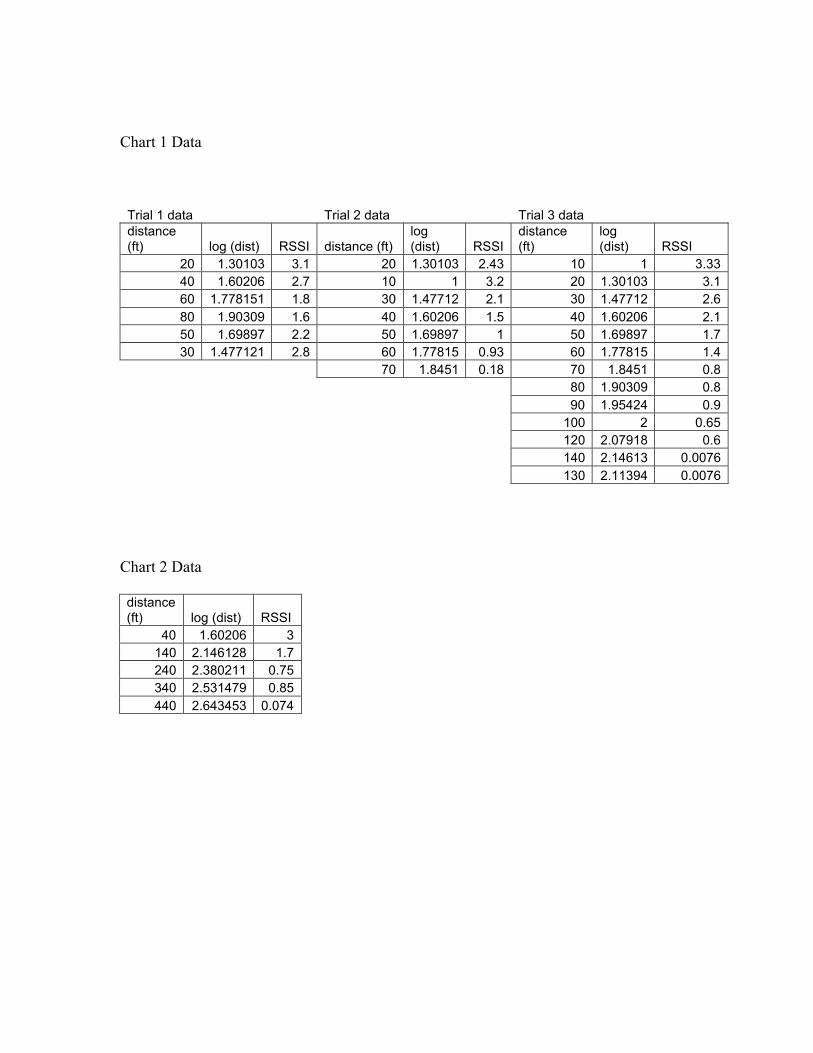
Chart 1 Data
Trial 1 data Trial 2 data Trial 3 datadistance(ft) log (dist) RSSI distance (ft)
log(dist) RSSI
distance(ft)
log(dist) RSSI
20 1.30103 3.1 20 1.30103 2.43 10 1 3.3340 1.60206 2.7 10 1 3.2 20 1.30103 3.160 1.778151 1.8 30 1.47712 2.1 30 1.47712 2.680 1.90309 1.6 40 1.60206 1.5 40 1.60206 2.150 1.69897 2.2 50 1.69897 1 50 1.69897 1.730 1.477121 2.8 60 1.77815 0.93 60 1.77815 1.4
70 1.8451 0.18 70 1.8451 0.880 1.90309 0.890 1.95424 0.9
100 2 0.65120 2.07918 0.6140 2.14613 0.0076130 2.11394 0.0076
Chart 2 Data
distance(ft) log (dist) RSSI
40 1.60206 3140 2.146128 1.7240 2.380211 0.75340 2.531479 0.85440 2.643453 0.074

Chart 3 Data
Trial 1 Trial 2 Trial 3
Angle RSSI angle RSSI angle RSSI
90 3 0 2.1 44.4 1.3
41.8 3 11.5 2.1 30 1
19.5 3.25 23.6 1.9 23.6 1.7
0 3.25 36.9 1.4 0 1.6
53.1 1 11.5 1.2
36.9 1.6
53.1 0.4