Pharmacok inetics ผศ. มนุพัศ โลหิต นาวี [email protected] manupatl@hotm ail.com.
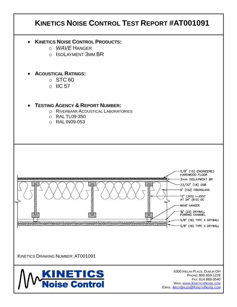
KINETICS NOISE CONTROL TEST REPORT #AT001091
• KINETICS NOISE CONTROL PRODUCTS: o WAVE HANGER o ISOLAYMENT 3MM BR
• ACOUSTICAL RATINGS: o STC 60 o IIC 57
• TESTING AGENCY & REPORT NUMBER: o RIVERBANK ACOUSTICAL LABORATORIES o RAL TL09-350 o RAL IN09-053
6300 IRELAN PLACE, DUBLIN OH PHONE: 800.959.1229
FAX: 614.889.0540 WEB: WWW.KINETICSNOISE.COM
EMAIL: [email protected]
KINETICS DRAWING NUMBER: AT001091

NVLAP Lab Code 100227-0
FOR: Kinetics Noise Control, Inc. Sound Transmission Loss TestDublin, OH RAL™-TL09-350
ON: Engineered Wood Flooring Floating on Kinetics 3 mm IsoLayment BR over 23/32 T&G Plywood on 11-7/8Inch TJI iLevel 230 Joist at 24 Inches on Center with 6.25 Inch Fiberglass Batt Insulation, Kinetics WAVE Hangers, Double Layer 5/8 Inch Type X Gypsum Board
Page 1 of 5
CONDUCTED: 30 November 2009
TEST METHOD
Unless otherwise designated, the measurements reported below were made with all facilities andprocedures in explicit conformity with the ASTM Designations E90-04 and E413-04, as well as other pertinent standards. Riverbank Acoustical Laboratories has been accredited by the U.S. Department of Commerce, National Institute of Standards and Technology (NIST) under the National Voluntary Laboratory Accreditation Program (NVLAP) for this test procedure (NVLAP Lab Code: 100227-0). A description of the measuring technique is available separately.
DESCRIPTION OF THE SPECIMEN The test specimen was designated by the client as engineered wood flooring floating on Kinetics 3 mm IsoLayment BR over 23/32 T&G Plywood on 11-7/8 inch TJI iLevel 230 Joist at 24 inches on center with 6.25 inch fiberglass batt insulation, Kinetics WAVE Hangers, double layer 5/8 inch Type X gypsum board. The overall dimensions of the specimen as measured were nominally 4.27 m (168 in.) wide by 6.10 m (240 in.) high and 397 mm (15.625 in.) thick. The specimen was constructed directly in the laboratory's 4.27 m (14 ft) by 6.10 m (20 ft) test opening and was sealed on the periphery (both sides) with dense mastic.
The description of the specimen was as follows: From the top down, the floor consisted of 5/8" engineered wood floor over 3 mm Kinetics IsoLayment BR underlayment on 23/32" span rated OSB attached to nominal 12" TJI joist with a fiberglass insulated cavity, a double layer of 5/8" gypsum board ceiling attached using Kinetics WAVE Hangers and hat track. A more detailed description of the test assembly appears in the following sections.
Prefinished Laminate Flooring With Underlayment
The finished floor consisted of HDF engineered wood flooring measuring 16 mm (0.625 in.)thick and provided as 89 mm (3.5 in.) wide and 901 mm (35.5 in.) long planks with tongue and groove quick clip edge details. Total weight of the laminate floor was 286.9 kg (632.5 lbs).

NVLAP Lab Code 100227-0
Kinetics Noise Control, Inc. RAL™-TL09-350
30 November 2009 Page 2 of 5
Prior to installation of the floor, Kinetics IsoLayment BR-3mm, a bonded recycled rubber material measuring 3 mm (0.12 in.) thick was loose laid over the subfloor assembly. Total weight of the underlayment was 52.8 kg (116.5 lbs).
Wood Subfloor and Support Assembly
The base floor consisted of 18 mm (23/32 in.) tongue and groove OSB board glued and nailed to iLevel TJI 230 Series Truss Joist and box sill using 63.5 mm (2.5 in.) long 8d nails at 203 mm (8in.) on center at the perimeter and 305 mm (12 in.) on center in the field. The 302 mm (11.875 in.) deep TJI joists horizontally spanned the width of the test opening and were attached to the sill plate with 10d nails. The joists were spaced on 610 mm (24 in.) centers, starting 305 mm (12in.) either side of the centerline. Total weight of the subfloor and support assembly was 538 kg (1,185 lbs).
Insulation
The cavities between the joists contained a layer of 159 mm (6.25 in.) thick by 610 mm (24 in.) wide unfaced fiberglass batt insulation. The fiberglass batts were stapled into the upper section of the cavity. The weight of the insulation was 34.5 kg (76 lbs).
Ceiling Assembly
The ceiling assembly consisted of 20 gauge roll-formed drywall furring channel (aka hat track) which measured 22 mm (0.875 in.) deep by 64 mm (2.5 in.) wide. Seven (7) full runs of drywall furring channels were mounted to Kinetics WAVE Acoustical Leaf Spring Ceiling Hangers,spaced at 610 mm (24 in.) by 1.22 m (48 in.) center to center. Runs of drywall furring channels extending the full length of the test specimen included splices which were overlapped 102 mm (4in.) and double wire tied with 18 gauge tie wire as necessary. Total weight of the channels as measured was 20.2 kg (44.5 lbs).
The hat track was held in place by the Kinetics WAVE Hangers, each fastened to the joists with two (2), 10 x 1-1/2 in. Round Washer Recex Lo Root screws measuring 38 mm (1.5 in.) long.The WAVE hangers were installed parallel to the joist to accommodate installation of the hat track perpendicular to the joists and spaced on 610 mm (24 in.) centers. For continuous run of hat track the WAVE 44 hangers were installed on the joists at 1.22 m (48 in.) centers. A total of 35 hangers were used in the field and four (4) WAVE 22 hangers were used in the corners only.

NVLAP Lab Code 100227-0
Kinetics Noise Control, Inc. RAL™-TL09-350
30 November 2009 Page 3 of 5
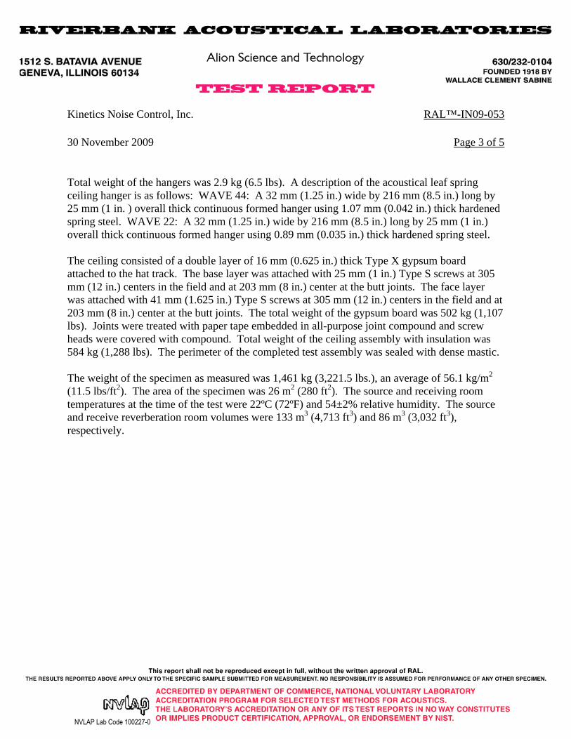
Total weight of the hangers was 2.9 kg (6.5 lbs). A description of the acoustical leaf spring ceiling hanger is as follows: WAVE 44: A 32 mm (1.25 in.) wide by 216 mm (8.5 in.) long by 25 mm (1 in. ) overall thick continuous formed hanger using 1.07 mm (0.042 in.) thick hardened spring steel. WAVE 22: A 32 mm (1.25 in.) wide by 216 mm (8.5 in.) long by 25 mm (1 in.) overall thick continuous formed hanger using 0.89 mm (0.035 in.) thick hardened spring steel.
The ceiling consisted of a double layer of 16 mm (0.625 in.) thick Type X gypsum board attached to the hat track. The base layer was attached with 25 mm (1 in.) Type S screws at 305 mm (12 in.) centers in the field and at 203 mm (8 in.) center at the butt joints. The face layer was attached with 41 mm (1.625 in.) Type S screws at 305 mm (12 in.) centers in the field and at 203 mm (8 in.) center at the butt joints. The total weight of the gypsum board was 502 kg (1,107lbs). Joints were treated with paper tape embedded in all-purpose joint compound and screw heads were covered with compound. Total weight of the ceiling assembly with insulation was 584 kg (1,288 lbs). The perimeter of the completed test assembly was sealed with dense mastic.
The weight of the specimen as measured was 1,461 kg (3,221.5 lbs.), an average of 56.1 kg/m2
(11.5 lbs/ft2). The transmission area used in the calculations was 26 m2 (280 ft2). The source and receiving room temperatures at the time of the test were 22ºC (72ºF) and 54±2% relative humidity. The source and receive reverberation room volumes were 133 m3 (4,713 ft3) and 86m3 (3,032 ft3), respectively.

NVLAP Lab Code 100227-0
Kinetics Noise Control, Inc. RAL™-TL09-350
30 November 2009 Page 4 of 5
TEST RESULTS
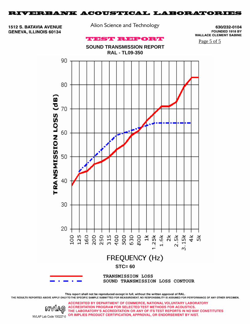
Sound transmission loss values are tabulated at the eighteen standard frequencies. A graphic presentation of the data and additional information appear on the following pages. The precision of the TL test data is within the limits set by the ASTM Standard E90-04.
FREQ. T.L. C.L. DEF. FREQ. T.L. C.L. DEF.
100 38 0.72 800 61 0.17 1125 43 0.64 1 1000 65 0.19160 44 0.49 3 1250 68 0.19
200 47 0.56 3 1600 71 0.14250 48 0.47 5 2000 71 0.14315 50 0.35 6 2500 73 0.13
400 53 0.45 6 3150 79 0.32500 55 0.32 5 4000 83 2.23630 59 0.26 2 5000 83 4.58
STC=60
ABBREVIATION INDEX
FREQ. = FREQUENCY, HERTZ, (cps)T.L. = TRANSMISSION LOSS, dBC.L. = UNCERTAINTY IN dB, FOR A 95% CONFIDENCE LIMITDEF. = DEFICIENCIES, dB<STC CONTOUR (SUM OF DEF = 32)STC = SOUND TRANSMISSION CLASS
Tested by __________________________ Approved by___________________________Marc Sciaky David L. Moyer
Experimentalist Laboratory Manager
NVLAP Lab Code 100227-0
Page 5 of 5SOUND TRANSMISSION REPORT
RAL - TL09-350
STC= 60
TRANSMISSION LOSSSOUND TRANSMISSION LOSS CONTOUR

NVLAP Lab Code 100227-0
FOR: Kinetics Noise Control, Inc. Impact Sound Transmission TestDublin, OH RAL™-IN09-053
ON: Engineered Wood Flooring Floating on Kinetics 3 mm IsoLayment BR over 23/32 T&G Plywood on 11-7/8 Inch TJI iLevel 230 Joist at 24 Inches on Center with 6.25 Inch Fiberglass Batt Insulation, Kinetics WAVE Hangers, Double Layer 5/8 Inch Type X Gypsum Board
Page 1 of 5
CONDUCTED: 30 November 2009
TEST METHOD
The measurements reported below were made with all facilities and procedures in explicit conformity with the ASTM Designations E492-04 and E989-06, as well as other pertinent standards. Riverbank Acoustical Laboratories has been accredited by the U.S. Department of Commerce, National Institute of Standards and Technology (NIST) under the National Voluntary Laboratory Accreditation Program (NVLAP) for this test procedure (NVLAP Lab Code: 100227-0). A description of the measuring technique is available separately.
DESCRIPTION OF THE SPECIMEN
The test specimen was designated by the client as engineered wood flooring floating on Kinetics 3 mm IsoLayment BR over 23/32 T&G Plywood on 11-7/8 inch TJI iLevel 230 Joist at 24 inches on center with 6.25 inch fiberglass batt insulation, Kinetics WAVE Hangers, double layer 5/8 inch Type X gypsum board. The overall dimensions of the specimen as measured were nominally 4.27 m (168 in.) wide by 6.10 m (240 in.) high and 397 mm (15.625 in.) thick. The specimen was constructed directly in the laboratory's 4.27 m (14 ft) by 6.10 m (20 ft) test opening and was sealed on the periphery (both sides) with dense mastic.
The description of the specimen was as follows: From the top down, the floor consisted of 5/8" engineered wood floor over 3 mm Kinetics IsoLayment BR underlayment on 23/32" span rated OSB attached to nominal 12" TJI joist with a fiberglass insulated cavity, a double layer of 5/8" gypsum board ceiling attached using Kinetics WAVE Hangers and hat track. A more detailed description of the test assembly appears in the following sections.
Prefinished Laminate Flooring With Underlayment
The finished floor consisted of HDF engineered wood flooring measuring 16 mm (0.625 in.) thick and provided as 89 mm (3.5 in.) wide and 901 mm (35.5 in.) long planks with tongue and groove quick clip edge details. Total weight of the laminate floor was 286.9 kg (632.5 lbs).

NVLAP Lab Code 100227-0
Kinetics Noise Control, Inc. RAL™-IN09-053
30 November 2009 Page 2 of 5
Prior to installation of the floor, Kinetics IsoLayment BR-3mm, a bonded recycled rubber material measuring 3 mm (0.12 in.) thick was loose laid over the subfloor assembly. Total weight of the underlayment was 52.8 kg (116.5 lbs).
Wood Subfloor and Support Assembly
The base floor consisted of 18 mm (23/32 in.) tongue and groove OSB board glued and nailed to iLevel TJI 230 Series Truss Joist and box sill using 63.5 mm (2.5 in.) long 8d nails at 203 mm (8 in.) on center at the perimeter and 305 mm (12 in.) on center in the field. The 302 mm (11.875 in.) deep TJI joists horizontally spanned the width of the test opening and were attached to the sill plate with 10d nails. The joists were spaced on 610 mm (24 in.) centers, starting 305 mm (12 in.) either side of the centerline. Total weight of the subfloor and support assembly was 538 kg (1,185 lbs).
Insulation
The cavities between the joists contained a layer of 159 mm (6.25 in.) thick by 610 mm (24 in.) wide unfaced fiberglass batt insulation. The fiberglass batts were stapled into the upper section of the cavity. The weight of the insulation was 34.5 kg (76 lbs).
Ceiling Assembly
The ceiling assembly consisted of 20 gauge roll-formed drywall furring channel (aka hat track) which measured 22 mm (0.875 in.) deep by 64 mm (2.5 in.) wide. Seven (7) full runs of drywall furring channels were mounted to Kinetics WAVE Acoustical Leaf Spring Ceiling Hangers, spaced at 610 mm (24 in.) by 1.22 m (48 in.) center to center. Runs of drywall furring channels extending the full length of the test specimen included splices which were overlapped 102 mm (4 in.) and double wire tied with 18 gauge tie wire as necessary. Total weight of the channels as measured was 20.2 kg (44.5 lbs).
The hat track was held in place by the Kinetics WAVE Hangers, each fastened to the joists with two (2), 10 x 1-1/2 in. Round Washer Recex Lo Root screws measuring 38 mm (1.5 in.) long.The WAVE hangers were installed parallel to the joist to accommodate installation of the hat track perpendicular to the joists and spaced on 610 mm (24 in.) centers. For continuous run of hat track the WAVE 44 hangers were installed on the joists at 1.22 m (48 in.) centers. A total of 35 hangers were used in the field and four (4) WAVE 22 hangers were used in the corners only.
NVLAP Lab Code 100227-0
Kinetics Noise Control, Inc. RAL™-IN09-053
30 November 2009 Page 3 of 5
Total weight of the hangers was 2.9 kg (6.5 lbs). A description of the acoustical leaf spring ceiling hanger is as follows: WAVE 44: A 32 mm (1.25 in.) wide by 216 mm (8.5 in.) long by 25 mm (1 in. ) overall thick continuous formed hanger using 1.07 mm (0.042 in.) thick hardened spring steel. WAVE 22: A 32 mm (1.25 in.) wide by 216 mm (8.5 in.) long by 25 mm (1 in.) overall thick continuous formed hanger using 0.89 mm (0.035 in.) thick hardened spring steel.
The ceiling consisted of a double layer of 16 mm (0.625 in.) thick Type X gypsum board attached to the hat track. The base layer was attached with 25 mm (1 in.) Type S screws at 305 mm (12 in.) centers in the field and at 203 mm (8 in.) center at the butt joints. The face layer was attached with 41 mm (1.625 in.) Type S screws at 305 mm (12 in.) centers in the field and at 203 mm (8 in.) center at the butt joints. The total weight of the gypsum board was 502 kg (1,107 lbs). Joints were treated with paper tape embedded in all-purpose joint compound and screw heads were covered with compound. Total weight of the ceiling assembly with insulation was 584 kg (1,288 lbs). The perimeter of the completed test assembly was sealed with dense mastic.
The weight of the specimen as measured was 1,461 kg (3,221.5 lbs.), an average of 56.1 kg/m2
(11.5 lbs/ft2). The area of the specimen was 26 m2 (280 ft2). The source and receiving room temperatures at the time of the test were 22ºC (72ºF) and 54±2% relative humidity. The source and receive reverberation room volumes were 133 m3 (4,713 ft3) and 86 m3 (3,032 ft3), respectively.

NVLAP Lab Code 100227-0
Kinetics Noise Control, Inc. RAL™-IN09-053
30 November 2009 Page 4 of 5
TEST RESULTS
Sound pressure levels at 1/3 octave intervals, normalized to 10 square meters, are given in tabular form. The impact insulation class, IIC, was computed in accordance with ASTM E989-06 and ASTM E492-04.
FREQ. Ln C.L. DEV FREQ. Ln C.L. DEV
100 63 0.76 8 800 50 0.23125 55 0.88 1000 48 0.23160 53 0.48 1250 45 0.29
200 56 0.62 1 1600 40 0.20250 58 0.58 3 2000 38 0.26315 57 0.37 2 2500 37 0.28
400 56 0.46 2 3150 30 0.44500 54 0.43 1 4000 24 0.59630 51 0.28 5000 20 1.43
IIC=57
ABBREVIATION INDEX
FREQ. = FREQUENCY, HERTZ, (cps)Ln = NORMALIZED IMPACT SOUND PRESSURE LEVEL, dBC.L. = UNCERTAINTY IN dB, FOR A 95% CONFIDENCE LIMITDEV. = DEVIATION, dB > IIC CONTOUR (SUM OF DEV = 17 ) IIC = IMPACT INSULATION CLASS* = INDICATES A CORRECTION HAS BEEN APPLIED TO DATA
DUE TO BACKGROUND NOISE LEVELS
Tested by __________________________ Approved by___________________________Marc Sciaky David L. Moyer
Experimentalist Laboratory Manager

NVLAP Lab Code 100227-0
Page 5 of 5IMPACT SOUND TRANSMISSION REPORT
RAL - IN09-053
IIC= 57
IMPACT SOUND PRESSURE LEVEL IMPACT INSULATION CLASS CONTOUR

NVLAP Lab Code 100227-0
Appendix to ASTM E492 Impact Sound Transmission Test
Kinetics Noise Control, Inc. RAL™-IN09-053
Additional Frequency Data for Impact Sound Testing
As requested by the client, normalized impact sound Pressure levels (Ln) values were calculated at additional test frequencies. Although the measurements were made in accordance with the procedures described in ASTM E492-04, they do not qualify as part of the standard. Since the results are representative of the test environment only, they are unofficial and intended for research and development guidelines rather than for commercial purposes. The normalized impact sound pressure level values at the additional frequencies were as follows:
RAL-IN09-053
1/3 Octave Center Frequency
Normalized Impact Sound Pressure Level
(Hz) (dB)
50 6063 6280 60
NVLAP Lab Code 100227-0
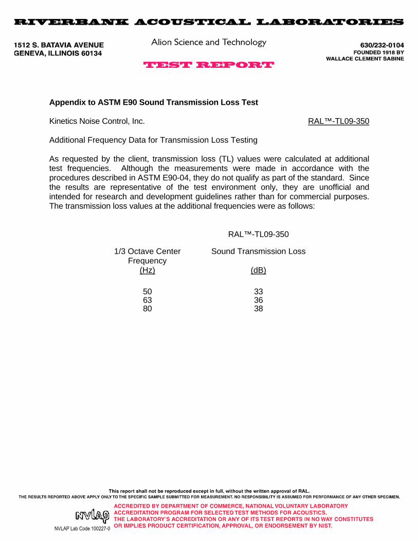
Appendix to ASTM E90 Sound Transmission Loss Test
Kinetics Noise Control, Inc. RAL™-TL09-350
Additional Frequency Data for Transmission Loss Testing
As requested by the client, transmission loss (TL) values were calculated at additional test frequencies. Although the measurements were made in accordance with the procedures described in ASTM E90-04, they do not qualify as part of the standard. Since the results are representative of the test environment only, they are unofficial and intended for research and development guidelines rather than for commercial purposes. The transmission loss values at the additional frequencies were as follows:
RAL™-TL09-350
1/3 Octave Center Frequency
Sound Transmission Loss
(Hz) (dB)
50 3363 3680 38