INERTIAL CONFINEMENT FUSION - home [MFE: DIII-D … · INERTIAL CONFINEMENT FUSION Annual Report...
69
INERTIAL CONFINEMENT FUSION Annual Report October 1, 2008 through September 30, 2009 GA-A26623 Assembly Micromachining Capsules/Foams NIF Target I-TIC for TARPOS Fill Tube Evolution X-Ray Resolution Target Funnel Tube in Be Capsule Starburst Pattern on Hohlraum Shock Timing Target SymCap AuB Halfraum Machined GDP Capsule Astroshock Target TPX Foam Laser Micro Machining
Transcript of INERTIAL CONFINEMENT FUSION - home [MFE: DIII-D … · INERTIAL CONFINEMENT FUSION Annual Report...

INERTIALCONFINEMENTFUSION
Annual Report
October 1, 2008through September 30, 2009
GA-A26623Asse
mb
ly M
icro
ma
chining
Ca
psule
s/Foa
ms
NIF
Targ
et
I-TIC fo
rTA
RPOS
Fill Tube
Evolutio
nX
-Ray
Reso
lution Ta
rge
tFunne
l Tube
in Be C
ap
suleSta
rburst Pa
ttern
on H
ohlra
umShock
Timing
Targ
etSym
Ca
pA
uB Ha
lfraum
Ma
chinedG
DP C
ap
suleA
stroshockTa
rget
TPXFoa
m
Lase
r Mic
ro M
ac
hining

DISCLAIMER
This report was prepared as an account of work sponsored by an agency of the United States Government. Neither the United States Government nor any agency thereof, nor any of their employees, makes any warranty, express or implied, or assumes any legal liability or responsibility for the accuracy, completeness, or usefulness of any information, apparatus, product, or process disclosed, or represents that its use would not infringe privately owned rights. Reference herein to any specific commercial product, process, or service by trade name, trademark, manufacturer, or otherwise, does not necessarily constitute or imply its endorsement, recommendation, or favoring by the United States Government or any agency thereof. The views and opinions of authors expressed herein do not necessarily state or reflect those of the United States Government or any agency thereof.

GA–A26623
RESEARCH AND DEVELOPMENT AND FABRICATION OF INERTIAL CONFINEMENT
FUSION TARGETS, COMPONENTS, AND COMPONENT TECHNOLOGY
ANNUAL REPORT TO THE U.S. DEPARTMENT OF ENERGY
FOR THE PERIOD OCTOBER 1, 2008 THROUGH SEPTEMBER 30, 2009
by PROJECT STAFF
Prepared under Contract No. DE-AC52-06NA27279 for the U.S. Department of Energy
GENERAL ATOMICS PROJECT 30272 DATE PUBLISHED: APRIL 2010
Project Staff FY09 IFT Annual Report
General Atomics Report GA–A26623 iii
LIST OF ACRONYMS
AES Auger electron spectroscopy AFM atomic force microscope Al aluminum Ar argon Au gold AuB gold boron Be beryllium CCD charge coupled device CD carbon deuterium CFTA capsule fill tube assembly CH carbon hydrogen CPM Center for Precision Manufacturing CR contact radiography CryoTARPOS cryogenic target positioner CTM cryogenic target mount CTS cryogenic target system Cu copper D2 deuterium DG droplet generator DImE Defect Implosion Experiment DLA diffusion limited aggregation DOE Department of Energy DR differential radiography DT deuterium-tritium DU depleted uranium DVB divinyl benzene EDS energy dispersive spectroscopy EDXS energy dispersive x-ray spectroscopy Fe iron FODPS fractional optical depth power spectrum FTIR Fourier transform infrared spectroscopy FWHM full width half maximum GA General Atomics Ge germanium GDP glow discharge polymer

FY09 IFT Annual Report Project Staff
iv General Atomics Report GA–A26623
HDC high density carbon HDRF high density resorcinol formaldehyde HED high energy density HEDP high energy density plasma hGXI hardened Gated X-ray Imager HL half-life ICF Inertial Confinement Fusion IDC Indirect Drive Capsule Center IFT Inertial Fusion Technology I-TIC ignition target inserter cryostat LANL Los Alamos National Laboratory LEH Laser Entrance Hole LLCS load, layer and characterization system LLE Laboratory for Laser Energetics LLNL Lawrence Livermore National Laboratory LMM Laser Micro Machining Center MIFEDS magneto inertial fusion electrical discharge system MS mass spectrometer MW molecular weight NC non-concentricity NIC National Ignition Campaign NIF National Ignition Facility NLUF National Laser Users Facility NNSA National Nuclear Security Administration NRL Naval Research Laboratory OD optical depth PAA poly acrylic acid PAMS poly-α-methyl styrene PMT photo multiplier tube PR Precision Radiography PS power spectrum PSDI phase-shifting diffraction interferometer PVA poly vinyl alcohol R/F resorcinol formaldehyde SBS styrene-butadiene-styrene SCD strong carbon deuterium SDRF standard density resorcinol formaldehyde SEM scanning electron microscopy

Project Staff FY09 IFT Annual Report
General Atomics Report GA–A26623 v
Si silicon Si-GDP silicon-doped glow discharge polymer Sn tin SNL Sandia National Laboratory SNRT Supernova Rayleigh-Taylor SSP Stockpile Stewardship Program T2B trans-2-butene Ta tantalum TARPOS Target Positioner TAS target alignment system TGA thermo gravimetric analysis Ti-GDP titanium-doped glow discharge polymer TMG tetramethyl germane TMP thermo mechanical package TMS tetramethyl silane U uranium UR/LLE University of Rochester Laboratory for Laser Energetics USAXS ultra small angle x-ray scattering XAS x-ray absorption spectroscopy XRF x-ray fluorescence

Project Staff FY09 IFT Annual Report
General Atomics Report GA–A26623 vii
TABLE OF CONTENTS
LIST OF ACRONYMS ............................................................................................................. iii
1. INTRODUCTION ............................................................................................................. 1
2. FABRICATION AND DEVELOPMENT CENTERS WITHIN GA IFT ................... 5 2.1. Capsules .................................................................................................................... 5 2.2. Center for Precision Manufacturing ......................................................................... 6 2.3. Foams and Materials Center ..................................................................................... 7 2.4. NIF Center ................................................................................................................ 8 2.5. Laser Micro-Machining Center ................................................................................ 8
3. DELIVERY SUMMARY .................................................................................................. 11 3.1. OMEGA Deliveries .................................................................................................. 11
3.1.1. Capsule Deliveries ......................................................................................... 12 3.1.2. Micromachining Deliveries ........................................................................... 13 3.1.3. Miscellaneous Deliveries ............................................................................... 14 3.1.4. Onsite LLNL Assembly Support ................................................................... 15
3.2. Z and Associated Facilities Deliveries ..................................................................... 15 3.2.1. Onsite SNL Assembly Support ...................................................................... 16 3.2.2. Establishment of a Machining and Assembly Area for Classified
Targets at SNL ............................................................................................... 16 3.3. NIF Deliveries ........................................................................................................... 16
3.3.1. Micromachining Deliveries ........................................................................... 17 3.3.2. Sub-Assembly Deliveries .............................................................................. 17 3.3.3. AuB and U Hohlraum Deliveries .................................................................. 17 3.3.4. Laser Machining Deliveries ........................................................................... 18
3.4. NLUF Deliveries ....................................................................................................... 19
4. NIF TARGET DEVELOPMENT AND SUPPORT ...................................................... 21 4.1. Indirect Drive Target Development .......................................................................... 21
4.1.1. NIF Capsule Fabrication and Metrology Development ................................. 21 4.1.2. Hohlraum Development and Fabrication ....................................................... 23 4.1.3. Key Hole and Starburst Window Development ............................................. 25 4.1.4. The NIF Cryogenic Target System ................................................................ 27 4.1.5. High Aspect Ratio Hoppe Glass Capsules Development for
NIF Diagnostics Experiments ........................................................................ 30 4.1.6. Precision Radiography ................................................................................... 32
FY09 IFT Annual Report Project Staff
viii General Atomics Report GA–A26623
4.2. Direct Drive Target Development ............................................................................. 37 4.2.1. Fill Tube Development for Plastic and Foam Capsules for OMEGA, NIF,
and Fast Ignition Experiments ....................................................................... 37 References for Section 4 ..................................................................................................... 39
5. OMEGA TARGET DEVELOPMENT ........................................................................... 41 5.1. Target Development .................................................................................................. 41
5.1.1. Iron Doped Hoppe Glass Capsule Development ........................................... 41 5.1.2. Defect Implosion Experiment Target Development ..................................... 42
5.2. Metrology Development ............................................................................................ 44 5.2.1. Improving Target Thickness Measurement with Dual Confocal System ..... 44
5.3. NLUF Development .................................................................................................. 47 5.3.1. Embedding Ruby Spheres into a Resorcinol Formaldehyde Aerogel
Sphere for Astrophysical Jet Experiments .................................................... 47 5.3.2. Fabrication of Doped Foams in Small Plastic Channels for Electron
Transport Experiments .................................................................................. 48 References for Section 5 ..................................................................................................... 51
6. SNL TARGET DEVELOPMENT .................................................................................. 53 6.1. Evolution of TPX Foams for Higher Uniformity and Densities ............................... 53 6.2. FY09 Machined Target R&D Work for SNL ........................................................... 53
7. PUBLICATIONS AND PRSENTATIONS LIST FY09 ................................................ 57 7.1. List of Publications .................................................................................................... 57 7.2. List of Presentations .................................................................................................. 63

Project Staff FY09 IFT Annual Report
General Atomics Report GA–A26623 1
1. INTRODUCTION
This report documents General Atomics’ (GA) fiscal year 2009 (FY09) activities for Inertial Confinement Fusion (ICF), a research and development program of the U.S. Department of Energy (DOE) National Nuclear Security Administration (NNSA). The program goals are controlled nuclear fusion at laboratory scales using large laser and pulsed power facilities in the U.S., and conducting experiments relevant to high energy density physics (HEDP) using those same facilities. The ICF Campaign, which includes the National Ignition Campaign (NIC) and HEDP experiments, is presently executed at the following facilities: Los Alamos National Laboratory (LANL), Lawrence Livermore National Laboratory (LLNL), Sandia National Laboratories (SNL), the University of Rochester Laboratory for Laser Energetics (UR/LLE) and GA. There are three major ICF facilities where this work is performed: the OMEGA glass laser at UR/LLE, the Z pulsed-power facility at SNL, and the National Ignition Facility (NIF) at LLNL which was completed in FY09. These facilities are supplemented by LANL’s Trident laser and other smaller lasers.
General Atomics’ Inertial Fusion Technology (IFT) division concentrates on producing the targets and doing the R&D for the targets for experiments that are carried out at the above facilities. Through target fabrication, GA supports the ultimate goal of the ICF Campaign to develop laboratory capabilities to create and measure extreme conditions of temperature, pressure, and radiation density, including thermonuclear burn conditions and achieving HEDP conditions. In this effort, GA supports all four of the strategies of NNSA’s ICF Campaign to accomplish this long-term goal:
1. Achieve ignition in the laboratory and develop it as a scientific tool for stockpile stewardship.
2. Support execution of HEDP experiments necessary to provide advanced assessment capabilities for stockpile stewardship.
3. Develop advanced technology capabilities that support long-term needs of stockpile stewardship.
4. Maintain robust national program infrastructure and attract scientific talent to the Stockpile Stewardship Program (SSP).
FY09 marked a major milestone with the completion of NIF in May 2009. Shortly thereafter in August 2009 NIF began shooting hohlraum targets for energetics experiments in which GA’s production support was central. These experiments were the first step towards support of the ignition campaign for 2010. NIF target fabrication included producing the majority of target components and sub-assemblies for the cryogenic gas filled hohlraum targets. These components included gold (Au) or gold/boron (AuB) hohlraums, Ge doped CH capsules, capsule fill tube assemblies (CFTA) with 10 µm fill tubes, thermo-mechanical components and associated sub-assemblies required for cooling to 20 K, as well as laser entrance holes (LEH). The targets produced also included those for cryogenic layering experiments at LLNL. Beyond the production activities, the ongoing developmental work on capsules with graded doped ablators, in particular Be and CH, continued in FY09. The many specifications are demanding and continue to become tighter as designs are refined, hence our work in

FY09 IFT Annual Report Project Staff
2 General Atomics Report GA–A26623
FY09 was geared towards improvements in capsules required for NIF. GA also supported the Cryogenic Target System (CTS) for the NIF by supplying LLNL-onsite engineering staff, including the chief engineer in charge of the CTS.
GA continued its support of NNSA’s ICF program for OMEGA by on time delivery of fully characterized target components and targets necessary to enable ICF and HEDP experiments as required by the shot schedule. The OMEGA target support accounted for the majority of components produced by GA in FY09, more than 5000 targets and components. Each shot-day or half-day required a new and generally completely different type of tightly specified and well-characterized target. The Z facility continued to increase its shot rate in FY09 and GA continued to produce many novel and different types of components for Z, made by techniques requiring significant development. GA supported Z on almost all of its nearly 200 shots in FY09, including close interactions on the design to enable fabrication of such complex targets and all in a timely manner. GA also continued its development of next generation of targets on Z in collaboration with SNL.
As the targets are the initial conditions for the experiments, the targets and components need to be accurately measured and characterized for each shot, which destroys the target. In providing these key components, the GA target fabrication group, an ISO 9001:2000 registered program, maintained excellent communication with the users of the targets to ensure adherence to the required quality and quantity, while continually seeking to improve processes to increase efficiency to enhance the performance of the team. In addition to getting extensive and generally very positive feedback from its customers in FY09, the GA staff authored a number of papers in refereed journals and presented work at major international conferences. Highlights of the GA ICF technology work performed under DOE Contract No. DE-AC52-06NA27279 in FY09 comprises the subject of this report.
In Section 2 we give a brief overview of the fabrication centers within the GA’s IFT group that ensure delivery of the various components needed for ICF experiments. In Section 3, we summarize the target deliveries for these facilities and include descriptions of target deliveries of note. In FY09, GA worked closely with all other sites to manage the rolling specification of hundreds of targets per year required for OMEGA, through weekly teleconference and video conference meetings under a Change Control Board (CCB). Such meetings ensured that target specifications for each facility shot-day, which is essentially a new experimental campaign, were specified well enough in advance for complete manufacture and characterization of the target to specification.
In Section 4, we summarize research and development work for the ignition campaign on the NIF (NIC Target Development). in Section 5 summarizes delivery support for OMEGA (NIC x-ray drive target production and NIC direct drive target production) as well as Section 6 for Z (SNL Target Development and Production). This development work has been presented to peers in the inertial fusion and HEDP community at major international conferences (e.g., Inertial Fusion Sciences and Applications (IFSA 2009) in San Francisco, the International Conference on Plasma Science (ICOPS) and the 23rd Symposium on Fusion Engineering (SOFE 2009) in San Diego, and the American Physical Society Division of Plasma Physics (APS/DPP 2009) in Atlanta. These sections have selected presentations from these major meetings; also included in these technical sections is closely related target work on fast ignition and inertial fusion energy funded via related contracts.

Project Staff FY09 IFT Annual Report
General Atomics Report GA–A26623 3
GA has brought together a dedicated and high-quality staff, an efficient management system, an understanding of the integrated program needs, the appropriate facilities and equipment, and a commitment to the customer, to produce targets, conduct R&D for the target supply, and support the ultimate goals of the ICF, NIC, and HEDP programs. Comments and requests for further information may be directed to the GA Inertial Fusion Technology Program Manager, [email protected], (858) 455-2931.

Project Staff FY09 IFT Annual Report
General Atomics Report GA–A26623 5
2. FABRICATION AND DEVELOPMENT CENTERS WITHIN GA IFT
Various production centers within GA’s IFT division are responsible for development and the fabrication of components, sub-assemblies and assemblies for the many and varied campaigns and associated experiments at NNSA facilities. Metrology is a common theme for the various centers where novel techniques are developed and then utilized across production centers. In addition many of the production processes involve transfer of components from one center to another during the fabrication cycle. Therefore, these centers are situated physically close to each other within GA-IFT’s La Jolla site and work closely together in an integrated fashion using common facilities and expertise to effect fabrication in an efficient manner.
2.1. CAPSULES
The Centers for Capsule Production (Direct Drive and Indirect Drive, DDC and IDC, respectively) are primarily responsible for the manufacturing of thin-layer microcapsule components and targets for experiments carried out at OMEGA, Z, NIF and other laser facilities for LLNL, LANL, UR/LLE, National Laser Users Facility (NLUF) and SNL. In FY09 the two Capsule centers produced approximately 1400 components and targets for 80 separate orders. Essentially all capsule fabrication utilized some aspect of our glow discharge polymer (GDPV) coater technology (Fig. 2-1.)
Fig. 2-1. A GDP coater (1 of 9) operated at General Atomics to pro-duce polymer and doped polymer capsules.
Capsule development for FY09 included expansion of Hoppe glass capsule production to include the introduction of iron doping. Additional work focused on high aspect ratio Hoppe glass targets.
LLNL and LANL deliveries focused on Hoppe glass and GDP capsules with gas permeation barriers. A new type of target was designed and fabricated for LANL’s DImE campaign, a precisely produced defect implosion gas tight target.
UR/LLE cryogenic experiments on OMEGA were supported by production of thin walled strong carbon deuterium (CD) and silicon doped GDP (Si-GDP) layer CD capsules. Capsules were also

FY09 IFT Annual Report Project Staff
6 General Atomics Report GA–A26623
delivered for use in qualifying the OMEGA-EP lasers. High density (200 mg/cc) resorcinol formaldehyde (R/F) foam capsules with a GDP layer and an attached fill tube were produced for room temperature surrogate shots.
NLUF deliveries included GDP capsules with a titanium doped GDP (Ti-GDP) layer for the Core Imaging campaign, drop tower glass as well as polymer capsules for the PRad campaign, and Ta crystal assemblies for the ICE:BCC Metals campaign.
2.2. CENTER FOR PRECISION MANUFACTURING
The Center for Precision Manufacturing (CPM) is responsible for the manufacturing of micro-machined components and machined targets for experiments carried out at OMEGA, Z, NIF and other laser facilities for LLNL, LANL, SNL, UR/LLE and several Universities. In FY09, the CPM produced a total of 2921 components and targets utilizing several technologies including diamond turning lathes and precision mills (Figs. 2-2 and 2-3). The majority of the components and targets are new and unique and thus has required the development of new fabrication and characterization techniques.
Fig. 2-2. The CPM lathe operation area includes 6 lathes in use.
Fig. 2-3. CPM mill operations.

Project Staff FY09 IFT Annual Report
General Atomics Report GA–A26623 7
The CPM works in close collaboration with our partners in the national laboratories to obtain target specifications well in advance to ensure timely delivery. This advanced planning is especially important for work involving component fabrication for the NIF. CPM engineers are in continual contact with LLNL personnel to rapidly prototype and implement new or modifications in design.
The CPM has fabricated, characterized and assembled several new types of targets and components in FY09, examples include: cone and shell Fast Ignition targets for UR/LLE, grooved capsules for LANL’s DImE campaign, curved hohlraums for LLNL, Thermo Mechanical Package (TMP) components for LLNL/NIC and Blast Wave targets for the University of Michigan.
2.3. FOAMS AND MATERIALS CENTER
The Foams and Materials (FMS) Center produces a wide range of components and performs R&D work towards fabricating first of a kind targets. These targets were for experiments performed by LLE, LLNL, AWE and various universities. The FMS center in FY09 produced a total of 113 components and targets. In addition, the FMS center provided support for PAMS mandrel fabrica-tion for both OMEGA and NIF sized capsules utilizing triple orifice microencapsulation, see Fig. 2-4.
In FY09, the FMS center continued its support of the NIF direct drive campaign, by working closely with LLE to further develop 3 mm diameter foam capsules with fill tubes for cryogenic layering experiments, and fabricated and delivered many assemblies used in layering experiments at LLE. The Center also developed techniques necessary to produce foam capsules at large diameters with a thin (gas retentive) GDP layer. Figure 2-5 shows a developmental GDP coater used to coat the thin GDP layer.
Fig. 2-4. A close in view of the PAMS mandrel fabrication in progress.
Fig. 2-5. A developmental GDP Coater in operation at GA to coat thin gas retentive layers onto foam capsules.
For NLUF shots on OMEGA, we were able to extend the AstroShock targets from two embedded spheres suspended only by a foam matrix, to nearly 50 spheres as those targets matured to the next level. As in previous work, these targets were made with no visible density perturbations to the foam layer.
FY09 IFT Annual Report Project Staff
8 General Atomics Report GA–A26623
2.4. NIF CENTER
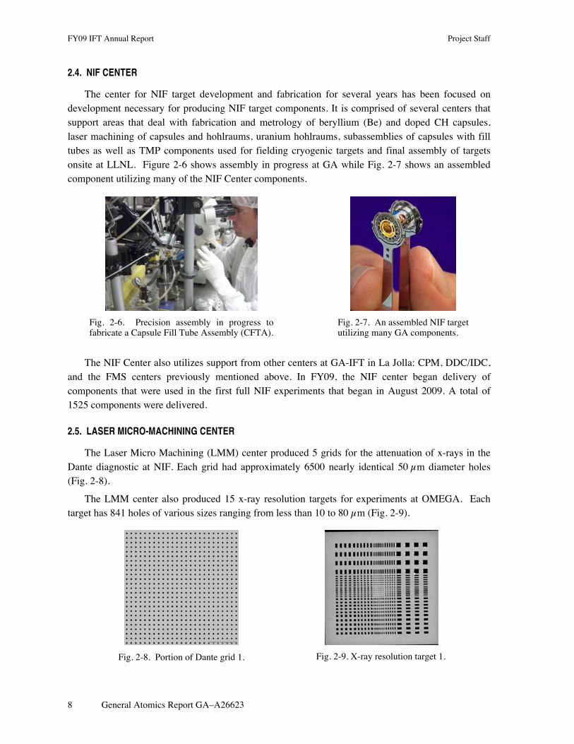
The center for NIF target development and fabrication for several years has been focused on development necessary for producing NIF target components. It is comprised of several centers that support areas that deal with fabrication and metrology of beryllium (Be) and doped CH capsules, laser machining of capsules and hohlraums, uranium hohlraums, subassemblies of capsules with fill tubes as well as TMP components used for fielding cryogenic targets and final assembly of targets onsite at LLNL. Figure 2-6 shows assembly in progress at GA while Fig. 2-7 shows an assembled component utilizing many of the NIF Center components.
Fig. 2-6. Precision assembly in progress to fabricate a Capsule Fill Tube Assembly (CFTA).
Fig. 2-7. An assembled NIF target utilizing many GA components.
The NIF Center also utilizes support from other centers at GA-IFT in La Jolla: CPM, DDC/IDC, and the FMS centers previously mentioned above. In FY09, the NIF center began delivery of components that were used in the first full NIF experiments that began in August 2009. A total of 1525 components were delivered.
2.5. LASER MICRO-MACHINING CENTER
The Laser Micro Machining (LMM) center produced 5 grids for the attenuation of x-rays in the Dante diagnostic at NIF. Each grid had approximately 6500 nearly identical 50 µm diameter holes (Fig. 2-8).
The LMM center also produced 15 x-ray resolution targets for experiments at OMEGA. Each target has 841 holes of various sizes ranging from less than 10 to 80 µm (Fig. 2-9).
Fig. 2-8. Portion of Dante grid 1. Fig. 2-9. X-ray resolution target 1.

Project Staff FY09 IFT Annual Report
General Atomics Report GA–A26623 9
The Lasers Center delivered approximately 80 simple parts (flags and squares cut from various foils) for experiments on OMEGA. In addition, the LMM provided several hundred parts (metal flags and other simple shapes in foil) produced by the FMS Center in which FMS center personnel utilize the laser-processing infrastructure provided by the LMM Center.

Project Staff FY09 IFT Annual Report
General Atomics Report GA–A26623 11
3. DELIVERY SUMMARY
3.1. OMEGA DELIVERIES
GA supplied approximately 3100 target components, assemblies or sub-assemblies to LLNL, LANL, UR/LLE and others in FY09. Capsules and micromachined components comprise the majority of the components built at GA in support of this work. Figure 3-1 shows the deliveries for FY09 by laboratory or program on a quarterly basis. Table 3-1 summarizes these deliveries by major component types: capsules, hohlraums and “packages” that included foam components, assemblies, and flat plates with various precision machined surface perturbations. A “special” components section includes precision capsule on cone parts and assemblies for fast ignition which in some cases can be challenging to fabricate.
Fig. 3-1. FY09 deliveries by laboratory by quarter.
Table 3-1 FY09 Deliveries by Laboratory and Types of Components
Lab Capsule Hohlraum Package Special Grand Total LANL 90 54 31 237 412 LLE 962 221 86 1269 LLNL 52 163 241 77 533 NLUF 107 85 413 228 833 SNL 11 22 33 Grand Total 1211 313 928 628 3080

FY09 IFT Annual Report Project Staff
12 General Atomics Report GA–A26623
3.1.1. Capsule Deliveries
Capsule Support for UR/LLE. The capsule centers (DDC and IDC) coordinated delivery of 962 targets for 53 separate orders in 2009 to UR/LLE. While a number of different targets were delivered, the majority of the effort was focused on capsules for cryogenic shots on OMEGA.
Cryogenic OMEGA shots primarily used thin walled strong CD capsules layered with DT and shot cryogenically. Capsule wall thicknesses were a challenging 5 or 10 µm thick wall with tight tolerances. We continued to supply capsules with an outer silicon doped Si-GDP layer developed in FY08. Metrology of these capsules was essential to ensure specified wall uniformity required for the layering process as well as outer surface finish. In addition, as in prior years, buckle pressure of sample capsules from each batch was measured to ensure survival during the fill process at LLE.
The capsule centers supported a number of additional shot campaigns on OMEGA. Table 3-2 illustrates the variety of the various types and the experiments they supported.
Table 3-2 Campaigns Requiring Different Capsule Types
Capsules design Thickness Experiment CD 5-10 µm Cryo 20 µm Preheat 40 µm Shock Ignition CD/CH Various/ 1 µm Shock Timing Fast Ignition CH 15-40 µm Neutron diagnostic dev 20 µm Mass equivalent Glass 2 PRad CH/Resorcinol-Formaldehyde Foam (with fill tube)
10 µm/ 60-80 µm Foam implosion
We also supported LLE by producing a number of precision planar targets made of GDP to study ablator material properties. These included 20-50 µm planar GDP and Germanium doped GDP (Ge-GDP) foils in support of the Spherical Shock, ThermCond and Ablator EOS campaign experiments.
NLUF Capsules. We supported a number of NLUF experiments by providing 107 capsules of different varieties including: GDP capsules with a titanium (Ti) doped inner layer for Core Imaging, glass capsule backlighters, polymer capsules and spheres for Proton Radiography, and complex stacked assemblies with tantalum (Ta) crystals for the ICE:BCC experiments.
Capsule Support for LLNL. Our group coordinated delivery of 52 targets for 7 separate deliveries in 2009 to LLNL. Several target designs were supported including multi-layered CH capsules with a PVA permeation barrier with associated gas fills, once again to be used as backlighters for various campaigns including TaOpacity shots on OMEGA. The capsule centers also assisted in the

Project Staff FY09 IFT Annual Report
General Atomics Report GA–A26623 13
developmental effort for direct drive on NIF: 3 mm diameter capsules were produced, which were either then fitted with a fill tube as described in section 4.2 or were directly fielded in cryogenic layering experiments at LLE.
Capsule Support for LANL. Our group coordinated delivery of 90 targets for 7 separate orders in 2009 to LANL. Orders included new target designs: Hoppe glass doped with iron (Fe), and a new class of defect implosion gas tight target, the DImE campaign. For the Fe-doped Hoppe glass production, the Si-GDP conversion process was modified to include ferrocene as a doping pre-cursor. Results indicated we achieved the 1 at. % doping level requested. The new target, pictured below in Fig. 3-2, was a multi-step, multi-disciplinary process requiring micromachining for an inner band or “channel”, GDP coating and mandrel removal, deposition of a permeation barrier to seal the capsules for subsequent gas fill, and metrology of channel size and permeation characteristics of the capsule. We developed proper micromachining techniques to create the desired channel on mandrels, determined the limits on aspect ratio imposed by GDP coating and mandrel pyrolysis, and modified our aluminum sputter coasting process to obtain longer permeation rates to create a capsule with acceptable thickness, surface roughness, as well as a permeation barrier that would cover the banded region to allow for deuterium and tritium gas fills.
Fig. 3-2. Xradia image of a DImE capsule illustrating the equatorial channel, 30 µm wide and 10 µm deep.
3.1.2. Micromachining Deliveries
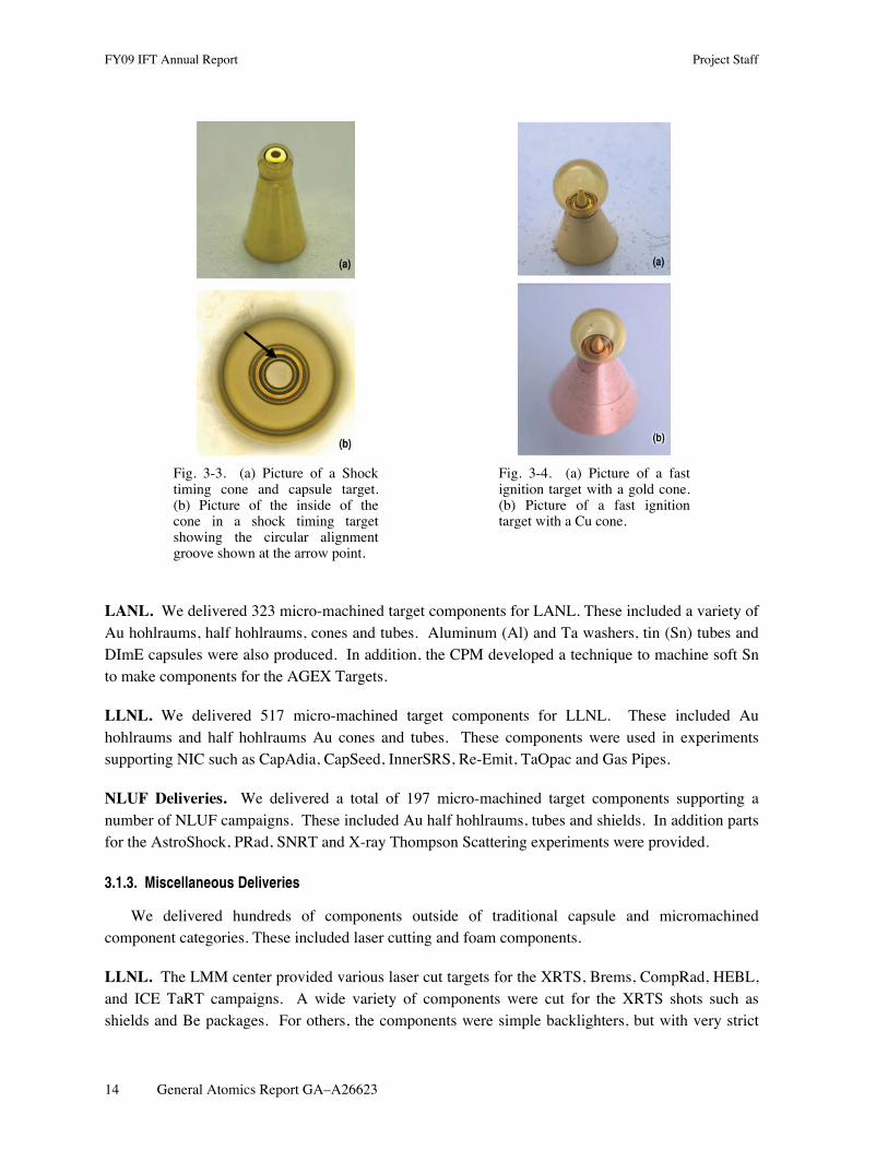
LLE. We delivered 105 target components for LLE. The majority of the deliveries were cone in shell targets, Shock Timing and Advanced Ignition targets. This effort included machining of CH capsules as well as Au components coupled with precision assembly of these components into full targets. The Shock Timing targets are used to observe shock-breakout on imploding capsules [Fig. 3-3(a)]. Lessons learned during the fabrication of the Shock Timing targets were implemented in the fabrication of KeyHole targets used to investigate shock timing on the NIF. An example is a machined annular feature on the inside of the cone to facilitate viewing and focusing the VISAR diagnostic is shown in Fig. 3-3(b).
The special characteristic of the Advanced Ignition targets is the accurate position, to within 10 µm, of the tip of the cone with respect to the center of the capsule both in the radial and axial directions. Figure 3-4 illustrates two examples of Advanced Ignition targets: one with a Au cone and one with a copper (Cu) cone, respectively.
FY09 IFT Annual Report Project Staff
14 General Atomics Report GA–A26623
Fig. 3-3. (a) Picture of a Shock timing cone and capsule target. (b) Picture of the inside of the cone in a shock timing target showing the circular alignment groove shown at the arrow point.
Fig. 3-4. (a) Picture of a fast ignition target with a gold cone. (b) Picture of a fast ignition target with a Cu cone.
LANL. We delivered 323 micro-machined target components for LANL. These included a variety of Au hohlraums, half hohlraums, cones and tubes. Aluminum (Al) and Ta washers, tin (Sn) tubes and DImE capsules were also produced. In addition, the CPM developed a technique to machine soft Sn to make components for the AGEX Targets.
LLNL. We delivered 517 micro-machined target components for LLNL. These included Au hohlraums and half hohlraums Au cones and tubes. These components were used in experiments supporting NIC such as CapAdia, CapSeed, InnerSRS, Re-Emit, TaOpac and Gas Pipes.
NLUF Deliveries. We delivered a total of 197 micro-machined target components supporting a number of NLUF campaigns. These included Au half hohlraums, tubes and shields. In addition parts for the AstroShock, PRad, SNRT and X-ray Thompson Scattering experiments were provided.
3.1.3. Miscellaneous Deliveries
We delivered hundreds of components outside of traditional capsule and micromachined component categories. These included laser cutting and foam components.
LLNL. The LMM center provided various laser cut targets for the XRTS, Brems, CompRad, HEBL, and ICE TaRT campaigns. A wide variety of components were cut for the XRTS shots such as shields and Be packages. For others, the components were simple backlighters, but with very strict

Project Staff FY09 IFT Annual Report
General Atomics Report GA–A26623 15
requirements on edge quality. For Brems and CompRad, we were able to provide backlighters with a very thin wire attached on the substrate.
3.1.4. Onsite LLNL Assembly Support
Target fabrication at GA includes an onsite team at LLNL. In FY09, the LLNL assembly team supported over 225 shots at OMEGA and fabricated over 100 targets for the NIF commissioning experiments. The target fabrication team developed innovative procedures to manipulate and characterize unique target designs. The support team also produces Be sputtered capsules and spent the last year refining fixturing and alignment processes to meet NIF design specifications.
3.2. Z AND ASSOCIATED FACILITIES DELIVERIES
In FY09 the refurbished Z machine had 147 shots. The deliveries for Z are summarized below in Table 3-3.
Table 3-3 Target Fabrication Support Provided for SNL in FY09
Facility
Targets
Micromachined Components
Produced
Foams Z 139 170 60 Saturn 18 NIF 6 collimators
Deliveries for Z included classified and non-classified work performed at GA, which included component fabrication, assembly, metrology and testing of various targets. In FY09 this capability was expanded at SNL, including commissioning a classified production facility equipped with state of the art metrology equipment. This increased onsite classified production capacity for Z while classified development of new targets continues onsite at GA La Jolla. GA onsite work at Sandia for Z includes foam component fabrication and metrology and assembly support as it has in the past decade for Z experiments.
Machining Center Deliveries for SNL. We delivered a total of 120 micro-machined target components to support Z-pinch experiments.
Capsule Support for SNL. Our group coordinated delivery of 10 targets for two separate deliveries in 2009 to SNL. We continued support for developmental Fast Igniter targets, supplying the inner and outer GDP hemi capsules.
3.2.1. Onsite SNL Assembly Support
The on-site effort at SNL is designated “Target Fabrication” by SNL. This group provided targets for 3 facilities: Z, Saturn, and NIF (collimators tested at OMEGA). In FY08 the Target

FY09 IFT Annual Report Project Staff
16 General Atomics Report GA–A26623
Fabrication and Load Assembly (Ktech) groups were combined under the direction of SNL’s Z Operations organization. This new organizational structure was meant to improve product flow and quality. In this arrangement, the Target Fabrication group provided direction for Load Assembly and coordinated the efforts between the two groups. In January 2009 SNL reorganized and moved Target Fabrication from the Z Operations organization to the Z Science organization. This was done to allow Target Fabrication the freedom to focus on the development, production and characterization of new target designs. To support the new targets characterization and machining facilities were brought online at SNL. On November 1, 2008 machinist Patrick Opsahl was transferred from the La Jolla site to the SNL site and on-site production of targets began. Also on November 1, 2008 a new employee was added, Korbie Killebrew, tasked with developing and executing the characterizations required for new targets. The characterizations now include radiography via Xradia Micro XCT, surface finish via Wyko, optical characterization and pressure testing. In addition to this characterization equipment, GA purchased an ultrasound for on-site use.
3.2.2. Establishment of a Machining and Assembly Area for Classified Targets at SNL
As mentioned above, in FY09 GA expanded the La Jolla classified machining capabilities as well as metrology onsite at SNL. A diamond turning machinist was also relocated from California to New Mexico to support the transfer. Now the majority of SNL classified targets are machined, assembled, and characterized onsite at SNL by GA staff. The capability in La Jolla has been maintained for R&D and complicated targets that exceed the SNL onsite capabilities, and as spare capacity to handle temporary production rate increase.
3.3. NIF DELIVERIES
GA’s NIF deliveries are summarized in Table 3-4. These include deliveries for energetics experiments as well as many components for prototype development, layering and other developmental experiments. In addition to these deliveries the GA team provided personnel onsite at LLNL who led aspects of final assembly as well as supporting testing of targets before fielding on NIF.
Table 3-4 NIF Deliveries
Qtr 1 Qtr 2 Qtr 3 Qtr 4 CFTA 5 19 27 45 Diagnostic band 15 29 52 16 Hohlraum 34 42 78 86 LEH 0 32 98 82 TMP subassembly 8 52 60 80 Window washer 207 110 130 218
Total(a) 269 284 445 527 (a)The above table sums to Qty 1525.

Project Staff FY09 IFT Annual Report
General Atomics Report GA–A26623 17
3.3.1. Micromachining Deliveries
We delivered over 1200 micro-machined target components in support of ignition for the NIC. The components are part of the TMP that include Al cans and diagnostic bands, Au LEH inserts, Al window washers, GXD plugs, Au cones and machined capsules.
A good working relationship with LLNL and dedicated equipment has allowed for quick turn around of part requests as a result of design changes or the need for test parts. With continuous component fabrication improvements and the TMP design maturing the center is evolving into a production facility that will be able to produce hundreds of components per year to ensure success of the NIF.
During FY09 several types of TMP were made including; Scale 0.7, Scale 0.9 SymCap, Scale 0.9 IgLT, Scale 0.9 ConvAbl, Scale 1.07 SymCap, Scale 1.07 KeyHole, and Scale 1.07 Re-Emit.
Collaboration between GA and LLNL resulted in the successful completion of the DOE Level 2 Milestone, on September 18, 2009, for fabrication, assembly, metrology and proof of cryogenic gas-tightness at 18°C of the first article of a 1.07 Scale KeyHole target design.
3.3.2. Sub-Assembly Deliveries
Sub-assembly of capsules and TMPs was transferred into production in FY09 and provided critical components for NIF. We delivered a total of 94 capsule fill tube assemblies (CFTA) and 220 TMP subassemblies for the various types of designs and experiments listed above in the micromachining section. In addition, we began the process and transfer of these activities to LLNL, while retaining them at GA to allow for increased capacity required in FY10 and beyond. In addition this enabled easier transport from sub-assembly area to final assembly where such parts are needed.
3.3.3. AuB and U Hohlraum Deliveries
We delivered a total of 253 half hohlraums used in experiments supporting the NIC such as ignition layering, vacuum experiments, and symmetry campaigns. Precision holes were milled into each half hohlraums to enable recording of the implosion. Of these components 167 of these were Au half hohlraums, 84 gold-boron (AuB) lined Au half hohlraums and 2 uranium (U) half hohlraums. Additionally these half hohlraums had a large flange added to them electroplated with Au and micro machined to lie flat on the TMP can surface to provide a large gluing surface (Fig. 3-5).
Fig. 3-5. AuB SymCap half hohlraums with flange.

FY09 IFT Annual Report Project Staff
18 General Atomics Report GA–A26623
3.3.4. Laser Machining Deliveries
3.3.4.1. Drilling of Controlled Funnel-Shaped Holes in Be and High Density Carbon. The production of funneled fill holes in CH capsules has previously been documented. As demonstrated in CH capsules, funnel shaped tubes in Be capsules improved the fill tube attachment process making the seating of the fill tube more reliable and consistent (Fig. 3-6).
Fig. 3-6. Funnel-shaped tubes in both Be and HDC capsules.
3.3.4.2. Precision positioning of hohlraums for laser machining of starbursts and other features. Coordinate system registration of (1) multi-axis motion control system, (2) hohlraum ,and (3) focused laser beam is not trivial but essential to align opposing starburst features to a few microns accuracy. Reference artifacts were employed to register the track of the motion control system in relation to the focused beam, and then the focused beam can be used to register the position of the hohlraum in turn.
3.3.4.3. Angled holes and construction of monolithic laminated pinhole arrays for hGXI. The requirements of hGXI are that the pinholes be drilled in high-Z materials that are thicker than 150 µm, both straight and at slight angles (Figs. 3-7 through 3-9). For technical reasons, it is also highly desirable to permanently attach a collimator plate to the pinhole plate. Both of these were achieved and two prototypes were made, and submitted to LLNL for evaluation.
Fig. 3-7. hGXI prototype assembly, 150 µm thick Pt foil containing 10 µm pinholes on 1 mm thick Ta substrate containing 100 µm dia-meter collimator holes concentri-cally drilled to less than 3 µm placement accuracy.

Project Staff FY09 IFT Annual Report
General Atomics Report GA–A26623 19
Fig. 3-8. X-ray contact radiography images of the hGXI prototype assembly. The holes in the third row have been intentionally shifted to the right.
Fig. 3-9. Cross section of straight and slanted 10 µm diameter holes through 200 µm thick Au. Photography is done in adjoining elements.
3.3.4.4. Development and design of CAD-CNC software for precision high-aspect ratio laser machining. The ease of producing diagrams of parts having many features with SolidWorks is well known. However, standard programs for converting CAD drawings into CNC (G-code) files do not work for precision high aspect ratio laser machining. The requirements of laser machining differ from mechanical machining, and laser-marking software is completely inadequate for high aspect ratio laser machining. GA worked with a vendor to produce a conversion program suitable to our needs and this program has subsequently been deployed with great success in early FY10 to support critical experiments for NIF.
3.4. NLUF DELIVERIES
We provided foam components for the AstroShock, PRad, and eXport campaigns. These included shock or jet tubes, which in some cases contained embedded spheres to mimic astrophysical phenomena. The embedded sphere targets and eXport doped foam targets are discussed in the development section of this report.
Foam cylinders were fabricated and delivered for the PRad and AstroShock experimental series. For the AstroShock shots, we were able to provide targets with 50 embedded spheres suspended only by the foam matrix, as well as targets with a sphere made of alumina nanopowder. These targets were made with minimal density perturbation to the foam layer surrounding the distribution of spheres.
Two very different types of targets were made this year for NLUF, one with embedded foam and the other with embedded metal wires. For the eXport campaign, a new type of electron transport target was fabricated with doped foam surrounded by full density plastic. The small foam block (0.2x0.4x0.4mm) was doped with an even distribution of alumina particles and assembled with Au shields with laser cut windows. We also made a set of novel targets for the PRad campaign consisting of embedded metal wires in Al and or Teflon.
NLUF targets were fully assembled in most cases by the GA team. However, in FY09 GA placed a new hire at LLE for additional assembly support to occur onsite the OMEGA facility. In addition, some minor assembly was completed at SNL by GA support staff.
Project Staff FY09 IFT Annual Report
General Atomics Report GA–A26623 21
4. NIF TARGET DEVELOPMENT AND SUPPORT
4.1. INDIRECT DRIVE TARGET DEVELOPMENT
4.1.1. NIF Capsule Fabrication and Metrology Development
In FY09, capsule fabrication focus was shifted to CH from Be. However, work on Be continued at the previous year’s level of effort as the point design for NIF was still Cu-doped Be.
4.1.1.1 Be Coater Standardization. The Be capsule effort focused on transitioning previous years or development into a deterministic process implemented on several coaters to allow sufficient capacity to produce capsules for NIF experiments.
The parameter that was closely followed in this standardization effort was the argon content of the Be capsules. Prior to this work, the argon content in different coaters could vary by more than 0.5 at. % from coater to coater. In addition, the argon content for the baseline coater decreased monotonically from its maximum during the coating run, (i.e. change with radius in the capsule) to its minimum level, while in other coaters the same behavior was not observed. This lack of reproducibility of the argon content including differences in the radial profile was of major concern and led to the effort to standardize coaters.
In particular, three coaters, one at GA and two at LLNL (operated by GA and LLNL personnel) were made to be identical on a sub-mm level in relative positioning of capsules with sputter guns, including the Be and Cu sputter guns. This required producing a detailed CAD model of the coaters, which allowed precise duplication in all three coaters with changes made to two of the coaters to render them identical to the chosen baseline coater.
The standardization effort provided important insight into the Be coating process as well. The radial variation (which could be accommodated in the physics design) was shown to be the consequence of sputter target thickness. Further, it was proven that the argon content depended on the relative position of the capsules with respect to the sputter guns in a very sensitive nature. Sub-mm differences in the relative positions led to large differences in the argon content as well as the measured radial profile. The results of the standardization are shown in Fig. 4-1, where the argon profiles fall within approximately 0.2 at. % range as a function of radius. In addition, the absolute value of the argon content was reduced to less than 0.3 at. % by proper positioning of the capsules in one of the coaters as shown in Fig. 4-2 after standardization. We intend to apply such reduction to other coaters to possibly provide more margin in achieving ignition.
4.1.1.2. Low Mode Improvements through “Super Mandrels”. To further gain margin in the probability of achieving ignition, we pursued improving the low mode surface finish of Be capsules to as much as 2 times better than the prescribed specification. Low mode Be capsule quality depends largely on the quality of the GDP mandrels used. Stresses in the coating process, polishing and stress

FY09 IFT Annual Report Project Staff
22 General Atomics Report GA–A26623
relaxation during the mandrel removal can, however, further degrade the low mode surface finish of Be capsules, despite having superior mandrels.
Fig. 4-1. Standardization resulted in argon profiles falling within approximately 0.2 at. % range as a function of radius.
Fig. 4-2. The absolute value of the argon content was reduced to less than 0.3 at. % by proper positioning of the capsules in one of the coaters after standardization.
Mandrels for Be capsules are produced using the GDP coating process on PAMS mandrels. Choosing the best possible PAMS mandrels and coating via the NIF standard GDP coating process, superior GDP mandrels can be produced, which should in turn result in superior quality Be capsules. To effect the desired 2 times improvement in low mode quality, we began by spheremapping every mandrel used in a coating run in a culling process. While this is time consuming, the gain in margin for ignition makes it a worthwhile investment.
The results are summarized in Fig. 4-3 which shows the low mode roughness in several different low modes for the mandrels used and the resulting Be capsules. When using “super mandrels” the Be capsule surface finish was indeed improved to nearly 2 times below specification. We utilized this process in producing capsules for the anticipated campaigns in late FY10 and early FY11 which will use Be capsules as the ablator material.

Project Staff FY09 IFT Annual Report
General Atomics Report GA–A26623 23
Fig. 4-3. Plot of super mandrels and the resulting Be capsules compared to mandrels used previously and the associated Be capsules. Using super mandrels the quality of Be capsules is greatly improved.
4.1.2. Hohlraum Development and Fabrication
Development in FY09 was focused early in the year on transferring the AuB lined Au hohlraum fabrication into production. NIF’s early shots required such hohlraum since uranium hohlraums could not be fielded until FY10. AuB-lined gold hohlraums had been fabricated in FY09 by depositing the AuB mixture onto a rotating Cu mandrel by a magnetron co-sputtering process, one hohlraum-half at a time. AuB mixture was deposited using separate guns, one for Au and the other for B. By varying the sputter rates of each gun, the concentration of the resulting AuB co-mix could be controlled in the as deposited film. However, in the early part of FY10 as larger batches of AuB hohlraums were produced, it became clear that this process led to major depletion of Boron in the AuB layer, upon leaching the Cu mandrel by nitric acid.
To remedy this problem, the mandrel was changed to aluminum where a base is used for the leaching. A protective layer was deposited on the mandrel before deposition of the AuB layer now using a AuB alloy target instead of from two separate sources. This largely mitigated the boron depletion post mandrel removal to levels (~ 10 relative % depletion) acceptable for production and for shots on NIF. To obtain the correct B at. % from the alloy sputter targets, they had to have the correct amount of boron as received from supplier. Although the AuB sputter targets were specified to have the desired B at. % in practice the observed B at. % in the hohlraum production process varied from target to target and on occasion it was outside the specifications. Therefore, each sputter target had to be tested for its B content in the hohlraum manufacturing process itself before it was allowed into the production process.
The coater was further modified to accept five parts at once increasing throughout from one per run. Another addition to the process was the introduction of a thickness monitor to track the deposited AuB amount on the cylinders in-situ. To calibrate the thickness monitor with the actual
FY09 IFT Annual Report Project Staff
24 General Atomics Report GA–A26623
coating rate on the cylinders, thick coatings of
€
>~ 3 µm (which were then measurable to 3% using the standard Z-mike shadowgraph technique) were deposited on surrogate cylinders. The thickness monitor’s “tooling factor” was then set to indicate the obtained rate. This process was repeated several time during the lifetime of the target to ensure the process was not drifting over time and as target wore thinner.
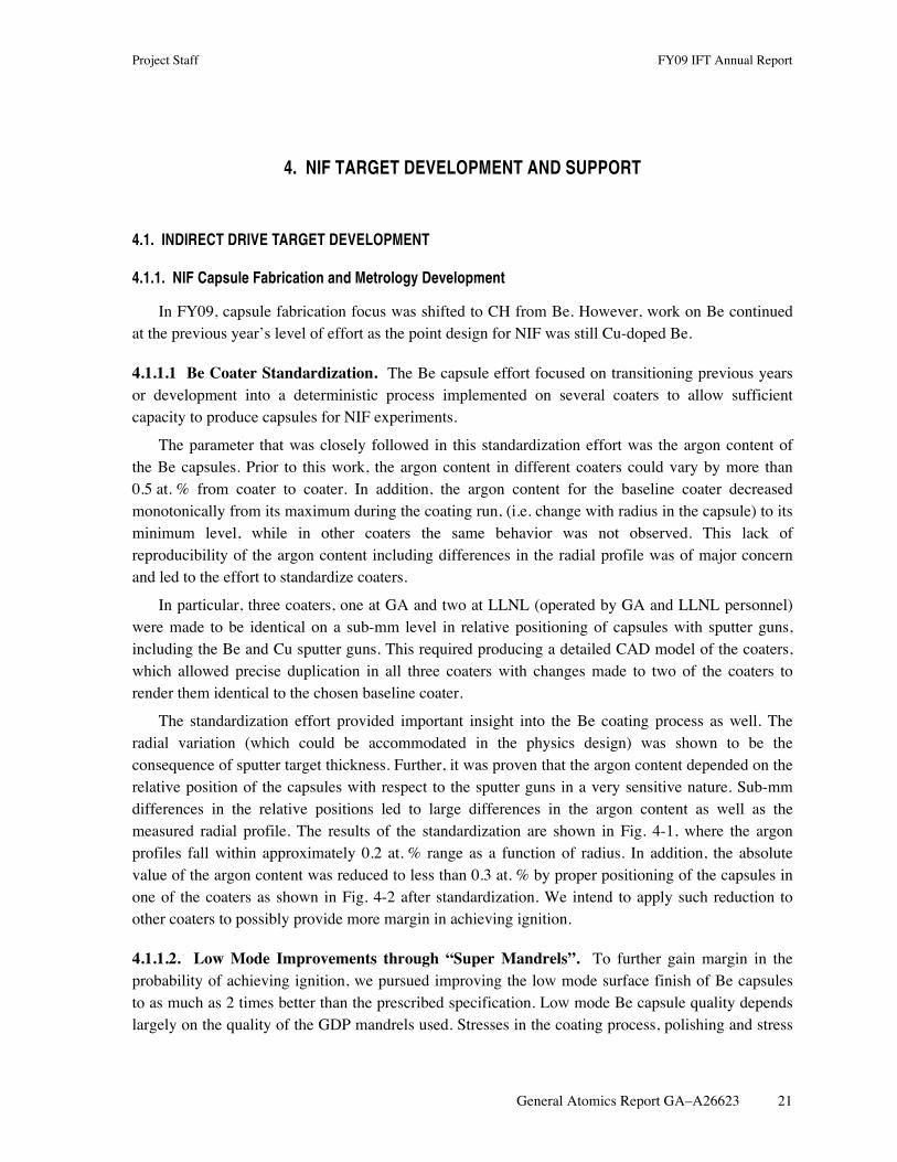
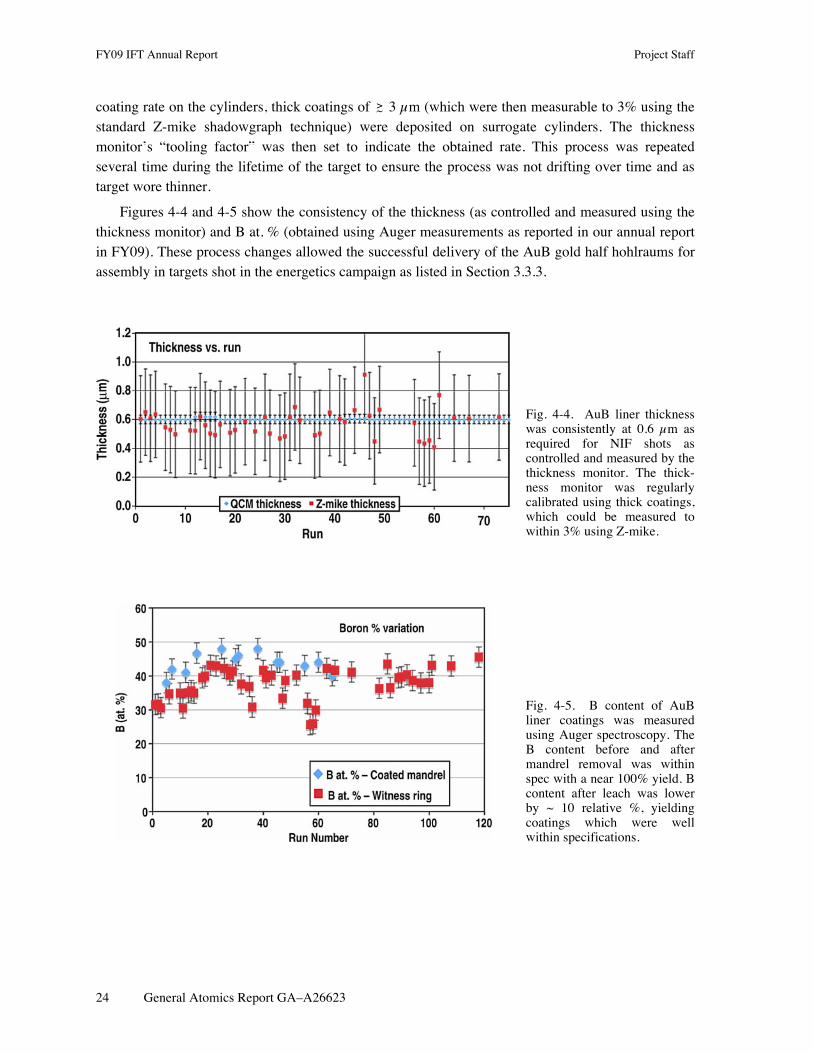
Figures 4-4 and 4-5 show the consistency of the thickness (as controlled and measured using the thickness monitor) and B at. % (obtained using Auger measurements as reported in our annual report in FY09). These process changes allowed the successful delivery of the AuB gold half hohlraums for assembly in targets shot in the energetics campaign as listed in Section 3.3.3.
Fig. 4-4. AuB liner thickness was consistently at 0.6 µm as required for NIF shots as controlled and measured by the thickness monitor. The thick-ness monitor was regularly calibrated using thick coatings, which could be measured to within 3% using Z-mike.
Fig. 4-5. B content of AuB liner coatings was measured using Auger spectroscopy. The B content before and after mandrel removal was within spec with a near 100% yield. B content after leach was lower by ~ 10 relative %, yielding coatings which were well within specifications.

Project Staff FY09 IFT Annual Report
General Atomics Report GA–A26623 25
4.1.3. Key Hole and Starburst Window Development
4.1.3.1. KeyHole Target. On September 18 2009, LLNL successfully completed the DOE Level 2 Milestone for the fabrication, assembly, metrology and proof of cryogenic gas-tightness at 18°C for the first article of a 1.07 Scale KeyHole target design. The CPM at La Jolla collaborated with LLNL in the design and fabrication of the components to achieve this Milestone as the CPM had successfully fabricated targets for similar Shock Timing experiments on OMEGA for several years. Initial micro-machining effort was placed into machining holes on GDP capsules of different wall thicknesses for insertion of the diagnostics cone. The micro machining of thick wall GDP capsules was very successful and procedures were developed to minimize cracking of the capsules during single point diamond machining, see Fig. 4-6 for a typical result. Other contributions made by the CPM were: simplifying the cone design at the tip to make fabrication easier and increase yield, adding a step to the diagnostic cone to accurately set the capsule position with respect to the tip of the cone, and the addition of a groove feature on the inside of the cone used for focusing VISAR. The groove feature is currently used on all Shock Timing Targets for OMEGA and has reduced setup time for VISAR diagnostics [refer to Fig. 3-3(b)].
Fig. 4-6. Photograph of a micro machined GDP capsule show-ing hole for cone.
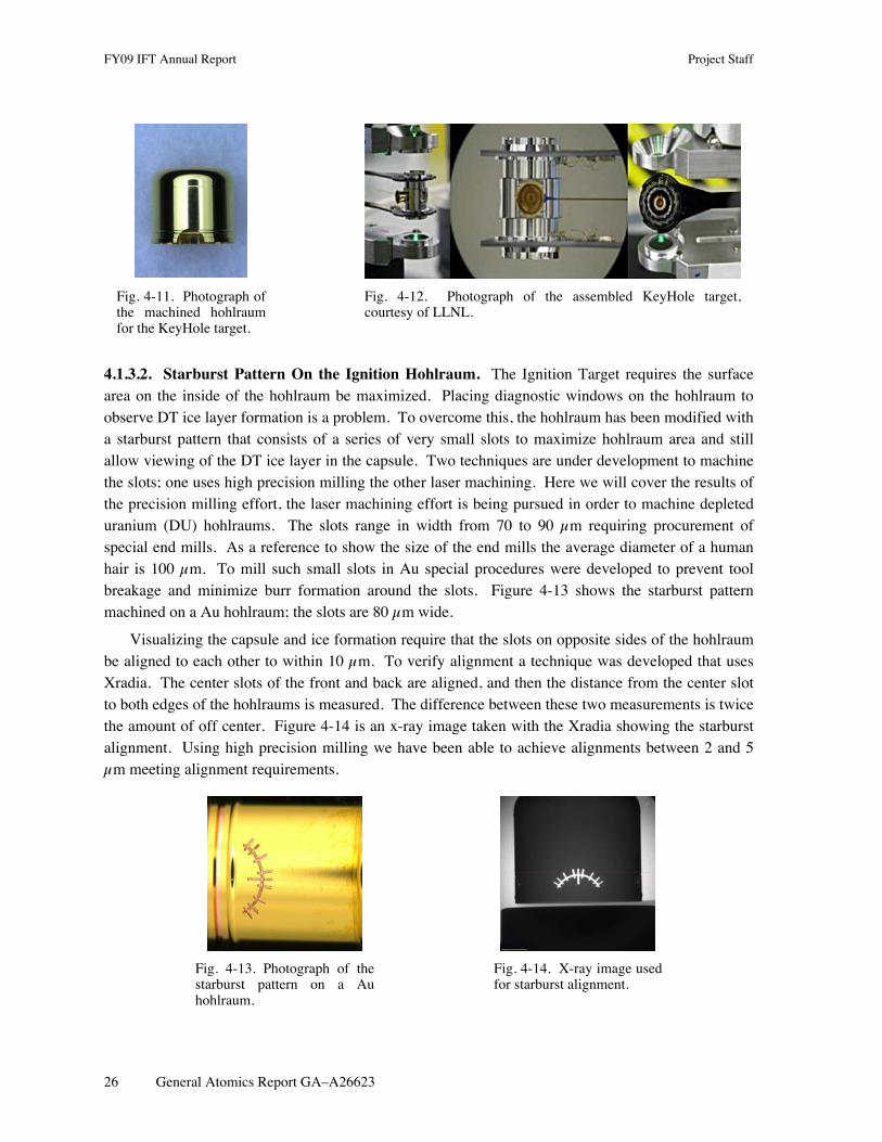
The CPM was responsible for the fabrication of all the components of the TMP for the KeyHole Target and includes the TMP can, diagnostic band, cone, LEH insert, window washer, machined capsule and holes on the hohlraum. Pictures of the different components, minus the washer and insert, are shown in Figs. 4-7 through 4-11. The components were metrologized both at GA and LLNL and demonstrated to meet required tolerances. Assembly of the components was completed at LLNL within specifications. Figure 4-12 is a photograph, courtesy of LLNL of the assembled target.
Fig. 4-7. Photo-graph of the TMP can for the Key-Hole target.
Fig. 4-8. Photo-graph of the diag-nostic band for the KeyHole target.
Fig. 4-9. Photograph of the diagnostic gold cone for the KeyHole target.
Fig. 4-10. Photograph of the machined cap-sule for the KeyHole target.
FY09 IFT Annual Report Project Staff
26 General Atomics Report GA–A26623
Fig. 4-11. Photograph of the machined hohlraum for the KeyHole target.
Fig. 4-12. Photograph of the assembled KeyHole target, courtesy of LLNL.
4.1.3.2. Starburst Pattern On the Ignition Hohlraum. The Ignition Target requires the surface area on the inside of the hohlraum be maximized. Placing diagnostic windows on the hohlraum to observe DT ice layer formation is a problem. To overcome this, the hohlraum has been modified with a starburst pattern that consists of a series of very small slots to maximize hohlraum area and still allow viewing of the DT ice layer in the capsule. Two techniques are under development to machine the slots; one uses high precision milling the other laser machining. Here we will cover the results of the precision milling effort, the laser machining effort is being pursued in order to machine depleted uranium (DU) hohlraums. The slots range in width from 70 to 90 µm requiring procurement of special end mills. As a reference to show the size of the end mills the average diameter of a human hair is 100 µm. To mill such small slots in Au special procedures were developed to prevent tool breakage and minimize burr formation around the slots. Figure 4-13 shows the starburst pattern machined on a Au hohlraum; the slots are 80 µm wide.
Visualizing the capsule and ice formation require that the slots on opposite sides of the hohlraum be aligned to each other to within 10 µm. To verify alignment a technique was developed that uses Xradia. The center slots of the front and back are aligned, and then the distance from the center slot to both edges of the hohlraums is measured. The difference between these two measurements is twice the amount of off center. Figure 4-14 is an x-ray image taken with the Xradia showing the starburst alignment. Using high precision milling we have been able to achieve alignments between 2 and 5 µm meeting alignment requirements.
Fig. 4-13. Photograph of the starburst pattern on a Au hohlraum.
Fig. 4-14. X-ray image used for starburst alignment.

Project Staff FY09 IFT Annual Report
General Atomics Report GA–A26623 27
4.1.4. The NIF Cryogenic Target System
General Atomics personnel assigned onsite at LLNL are participating in the assembly, test and commissioning of the NIF Cryogenic Target System (CTS). This work was performed under the direction and management of LLNL staff, and is part of the National Ignition Campaign (NIC).
The CTS team focused on two distinct tasks during FY09. The first task was to establish cryogenic target capability on the existing NIF target positioner (TARPOS). The second task was to continue the design, fabrication, assembly and test of hardware required to field ignition targets on the NIF laser.
I-TIC on TARPOS. The Ignition Target Inserter Cryostat (I-TIC), shown in Fig. 4-15, is designed to cool targets to cryogenic temperature and deliver them to the focus of the 192 laser beams. The I-TIC is designed to be used on either the existing TARPOS or the new cryogenic target positioner (CryoTARPOS).
Fig. 4-15. Ignition target inserter cryostat (I-TIC) in the NIF target positioner (TARPOS).
A series of tests have been successfully performed to commission the use of the I-TIC on the TARPOS. The first test performed was the Fit Check. This test verified the interfaces between the TARPOS and the I-TIC, including the lift apparatus, kinematic mount, electrical cables, and gas lines.
The next test was the Installation Qualification (IQ) test of the I-TIC on the TARPOS. The IQ test included installation of the I-TIC in the TARPOS vessel, checkout of instrumentation, demonstration of target installation, and shroud function tests.
Next was a series of tests to prove the Operational Qualification (OQ) of the I-TIC. The first OQ test was designed to demonstrate that the I-TIC could field room temperature targets in NIF. These targets incorporate the same magnetic target base used for shots on Nova, OMEGA, and during the NIF Early Light campaign. The completion of this OQ test allowed the cryogenic testing of the I-TIC to continue during the day while room temperature shots were continued at night.
The second OQ test included the operation of the I-TIC at cryogenic temperature. This test demonstrated successful operation of the compressor skid, helium plumbing and cryocooler coldhead.
The third OQ test demonstrated that the I-TIC met the requirement on the maximum amount of condensate deposited on the target before shot time. In this test, the target was replaced by a quartz

FY09 IFT Annual Report Project Staff
28 General Atomics Report GA–A26623
deposition monitor, which was cooled to cryogenic temperature. The data showed that the I-TIC thermal shrouds will limit the thickness of condensate to well under the 100 nm specification.
The fourth OQ test was the target vibration test and involved mounting a surrogate target on the I-TIC gripper. The target included a cube-shaped hohlraum, the vibration of which was measured by three capacitance gauges. Tests were performed with the target at both room and cryogenic temperature. Cryogenic tests were performed with the cryocooler on, with the cryocooler in bypass mode, and during opening of the shroud mechanism.
The first NIF laser shot of a vacuum target cooled to approximately 20 K by the I-TIC was performed in June 2009. The I-TIC shrouds successfully limited condensation on the target to well under required values. As programmed, the cryocooler went into bypass mode 60 s before the shot to limit target vibration. The shrouds then opened 10 s before the shot and exposed the cold target to the NIF laser.
A task closely associated with I-TIC qualification was the assembly and test of the target gas manifold. This system controls the gas environment inside a target, including initial evacuation, introduction of tamping gas inside hohlraums and gas pipe targets, and insertion of liquid deuterium inside target capsules. The CTS team installed the target gas manifold in the NIF facility alongside the TARPOS and performed commissioning tests.
Once the I-TIC and the target gas manifold were commissioned, the NIF laser was ready to shoot gas-filled cryogenic targets. The I-TIC is now routinely used to field cryogenic shots with the experimentalists varying parameters such as target temperature, gas fill pressure and composition, and shroud opening time.
Late in the fiscal year, the CTS team undertook the design, installation and commissioning of the upgraded thermal shrouds for the I-TIC. These new shrouds allow the fielding of the larger 1.07-scale targets on the NIF TARPOS.
CryoTARPOS. In addition to fielding the I-TIC on the TARPOS, the CTS team worked on the assembly and test of the CryoTARPOS, shown in Fig. 4-16. This device will be used to field ignition targets on NIF. It includes the equipment required to handle DT-filled targets to create the uniform DT ice layer and to characterize that layer.
Fig. 4-16. Cryogenic target positioner (CryoTARPOS) in the CTS Test Facility.

Project Staff FY09 IFT Annual Report
General Atomics Report GA–A26623 29
A major task completed early in the year was the assembly of the CryoTARPOS vacuum vessel. This structure includes the positioner vacuum vessel, the Load, Layer and Characterization System (LLCS) vacuum vessel, the rail bed, and the boom on its carriage. This assembly is supported at the front by a two-axis gimbal and at the rear by a pair of bipods.
All 12 vacuum gate valves were then installed on the CryoTARPOS vacuum vessel. This includes six vacuum glove-port valves, four gate valves to the high vacuum system and two gate valves to the ventilation system. The CTS team also installed and commissioned the three CryoTARPOS turbo-molecular vacuum pumps and the one cryogenic vacuum pump. The vessel was then pumped down to medium vacuum and demonstrated that it was leak tight by a successful helium leak check.
In preparation for operating the CryoTARPOS boom along its z-axis, the servo motor, mechanical linkage, and large motor control chassis were all installed. A next task was the operation of the CryoTARPOS boom z-axis drive. These components are used to extend the boom into the Target Chamber and to withdraw the boom back into the CryoTARPOS vacuum vessel during shot operations. As in actual NIF operation, the boom was driven by its servo motor and controlled by a large motor controller and shot control software.
The next step in commissioning was the successful operation of the CryoTARPOS vessel in ventilation mode using an external blower. This operational mode will be used during maintenance of the I-TIC and during installation and removal of non-ignition targets.
The CryoTARPOS assembly contains an x-ray system that it used to characterize the DT ice layer in the ignition targets. This assembly is configured with three orthogonal axes. Each axis consists of a microfocus x-ray source and a charge-coupled device (CCD) camera, both on positioning stages.
Due to its inherent hazardous operation, the x-ray system has first been tested in an off-line test bed. This test, called the X-ray Test Box, is a lead-lined cabinet, which can test one complete axis of x-ray imaging. The CryoTARPOS x-ray sources, pinhole array, shielding and CCD cameras have been operated and aligned in the X-ray Test Box.
The X-ray Test Box was also used for thermal testing of LLCS x-ray sources. The x-ray sources were operated for a typical layering cycle (greater than 10 h), and the temperature distribution of the source vacuum housing was shown to meet requirements (±0.3°C).
When the CryoTARPOS is operational, a second I-TIC will be required so that cryogenic targets can be shot on either the TARPOS or the CryoTARPOS. The assembly of the second I-TIC and associated compressor skid is currently underway.
Work on a new system, the Ignition Target Proofing Station, was begun. This system will be used to check the cryogenic operation of each ignition target before it is installed on the CryoTARPOS. In addition, this system can be used to determine the exact “recipe” (temperature, cooling rate, gradient, etc.) that is required to meet the DT ice smoothness specification.
The Design Review of the Ignition Target Proofing Station was successfully completed, as were all of the component drawings. The optical table and rail system, instrumentation racks and DT abort tanks have all arrived and been installed in the laboratory in the Target Fabrication Building.

FY09 IFT Annual Report Project Staff
30 General Atomics Report GA–A26623
4.1.5. High Aspect Ratio Hoppe Glass Capsules Development for NIF Diagnostics Experiments
Large glass capsules, approximately 1500 to 2000 µm in diameter and 4 µm in thickness, with low wall non-uniformities of less than 0.2 µm can be used to produce large numbers of neutrons in exploding pusher type implosions on OMEGA and NIF. These capsules are then used as neutron sources for development of neutron diagnostics at the two facilities, a critical endeavor for NIF. Such glass capsules can only be made using the Hoppe glass process, developed at GA over the last decade, as drop tower capsules can only reach a diameter of approximately 1000 µm with wall uniformity worse than 1 µm nominal. Through a number of optimizations the Hoppe process was successfully extended into two new regimes: a new larger 2100 µm diameter with 11 µm thick walls (Fig. 4-17), and a second smaller size of 1600 µm with 4 µm or thinner walls, surpassing the previous best of approximately1600 x 5 µm. The challenge encountered in making these capsules was degradation of the surface finish quality.
Fig. 4-17. Plot of possible range of Hoppe capsules that can be manu-factured in terms of diameter and wall thickness.
Varying process parameters to make approximately 1550 x 4 µm capsules yielded a total of nearly one hundred approximately 1550 µm diameter glass capsules ranging from 3.7 to 4.6 µm in thickness. Of these 100 or so capsules, approximately 30 were either very severely wrinkled or were determined to have small holes due to the thin walls.
The remaining 70 capsules were classified based on visual defects or Spheremap quality. Since the exact specifications needed for surface finish of these capsules is still unknown, pending shots at OMEGA and NIF, an arbitrary guideline was used to do the classifications. The NIF Spheremap specification for the pure CH point design was used as the standard (admittedly much too strict for this purpose, but this provided a starting point). Given this guideline, some capsules that had minimal visual defects were considered the best or as they were “target quality” when compared to the CH specification. Figure 4-18 shows what the Spheremap traces of a capsule containing a minor wrinkle or dimple commonly exhibits for Hoppe capsules of this very high aspect ratio. Spheremaps of these and other capsules also revealed low mode “wrinkling”. Figure 4-19 is a Spheremap of the visually “near target quality” capsules.
Given these results additional batches were made and capsules delivered to NIF and OMEGA for shots to determine the efficacy of these capsules in generating greater than 1010 neutrons or more at NIF, in FY10.

Project Staff FY09 IFT Annual Report
General Atomics Report GA–A26623 31
Fig. 4-18. Spheremap trace and power spectrum of a typical Hoppe glass capsule classified as “target quality” and contains a minor dimple or wrinkle on the surface.
Fig. 4-19. Spheremap of a Hoppe glass capsule that has been classified as “near target quality”.
All of the candidate capsules were buckle and burst tested for strength to ensure survival when fielded at the facilities. Only 5 capsules did not survive the 60 PSIA buckle test. All 26 capsules less than 4.0 µm were burst test to 13 atm, 2 capsules did not survive. Of the 44 capsules that were 4.0 µm or greater in wall thickness, three did not survive, including one of the twelve that appeared to be “target quality”. These results were consistent with what was expected for pure silica capsules of this size and wall thickness.

FY09 IFT Annual Report Project Staff
32 General Atomics Report GA–A26623
Pending results from OMEGA and NIF, we initiated investigation into other avenues to improve the yield of “target quality” capsules. The Spheremap results demonstrate that there is not a well defined correlation between wall thickness and capsule surface quality amongst these capsules. In addition to aspect ratio, or in this case wall thickness since all these capsules were approximately the same diameter, there must also be another factor that can be important. This factor is most likely Si content of the GDP prior to glass conversion. Higher Si content results in less shrinkage and pre-sumably more robust walls during the conversion process. Unfortunately, too high of Si content and the capsules do not survive the PAMS removal step. The window in Si content to make glass capsules from Si-GDP appears to be from 0.28 to 0.35g/cc Si. The higher the aspect ratio of glass capsule de-sired, the closer the Si content needs to be to the upper limit. Unfortunately, our ability to measure and control Si content is limited to no better than 5–10% or ± 0.02 to 0.03 g/cc. We will outfit the Si-GDP coater with more accurate mass flow controllers in the near future and will test this hypothesis.
4.1.6. Precision Radiography
4.1.6.1. Faster and More Quantitative Precision Radiography System for ICF Target Characterization
Rayleigh-Taylor instability growth places stringent limits on acceptable perturbations to x-ray propagation in ICF capsules [4-1,4-2]. From a target fabrication point-of-view, the imperfection is either in dimension or composition. Dimensional perturbations in the form of surface defects can be measured by a Twyman-Green type [4-3] Phase-Shifting Differential Interferometer (PSDI) [4-4], surface distortion and roughness can be measured by an AFM-based Spheremapper [4-5,4-6], and wall thickness non-uniformity can be measured by either a Filmetrics-based [4-7] or a Xradia-based [4-8] Wall-mapping instrument. Compositional perturbations can come from a variety of sources such as polycrystalline grains and angular variations in dopant/impurity profiles. A special Precision Radiography (PR) system was constructed to characterize the lumped effect of all aforementioned perturbations [4-9]. We made PR faster and more quantitative this year.
As shown in Fig. 4-20, x-rays transmit through two capsule walls; a scintillator then converts x-rays to visible photons, which then get detected by 16 fiber-coupled photo multiplier tubes (PMT). As the capsule rotates, 16 transmission traces are recorded along the latitude lines on the sample covering a wide band. The raw data is reported as the normalized PMT counts vs. the rotation angle [Fig. 4-21(a)]. The 16 traces correspond to 16 PMTs. Each spike represents approximately 1 µm tall dome defects. Each feature appears twice because as it passes the x-ray beam twice in one rotation.
In order to compare capsules with different trace appearance, we convert the data into the optical depth power spectrum (ODPS) format shown in Fig. 4-21(b). Optical depth (OD) is defined as
€
OD = − ln TT0
(4.1.6.1-1)
where
€
T is the count recorded with x-ray going through the sample and
€
T0 is the x-ray count without the sample. Therefore OD measures the effective x-ray absorption by the sample. For each OD trace, we obtain an average OD0. When the OD trace is normalized against the average, we obtain the fractional OD trace. After taking the power spectrum (PS), we obtain the fractional optical depth power spectrum (FODPS) curve shown in Fig. 4-21(b). For simplicity, all reference to ODPS from this point on mean FODPS.

Project Staff FY09 IFT Annual Report
General Atomics Report GA–A26623 33
Fig. 4-20. Schematics of the precision radiography system.
Fig. 4-21. (a) PR measures transmitted photon counts to 10-4 precision and report the raw data in normalized count vs. angle format. (b) The raw data is then converted to the ODPS format.
The two most important factors for the PR are the spatial resolution and the photon count rate. The spatial resolution is determined by the spot size of the x-ray source. A minimum resolution of 120 µm is required for NIF capsules. For this system the maximum spot size to maintain the minimum resolution is 120 µm.
The second factor, photon counting rate, arises from the need to measure the OD very precisely, requiring a very low noise level. The shot noise, N, is given by,
€
N =1n
(4.1.6.1-2)

FY09 IFT Annual Report Project Staff
34 General Atomics Report GA–A26623
where n is the total number of photons counted. Measuring the OD variation to the level of the NIF specification, 1 part in 104, requires a minimum photon count of 108. Therefore a high x-ray flux is needed to minimize the measurement duration.
The PR has been upgraded so that the typical measurement time for a single capsule has been reduced from one week to one day. This was achieved by installing a new x-ray tube to increase the count rate. The count rate,
€
C , is given by,
€
C∝ IV 2Ar 2
(4.1.6.1-3)
where
€
I is the x-ray intensity,
€
V is the tube voltage,
€
A is the anode selection parameter, and
€
r is the distance from the x-ray source to the detector. The new x-ray tube allows for increased
€
I and
€
A , and to decreased
€
r .
The initial x-ray tube for the PR had a working distance of about 3 cm, a chromium anode, and a 2.5 x 0.3 mm spot size. After several iterations and working closely with the x-ray tube vender to customize a source for our needs, we achieved a working distance of 0.9 cm, with a tungsten anode, and a 180 µm spot size. The reduction in the working distance alone increases the count rate by a factor of 9.
The reduction in spot size not only increases the resolution, but it also decreases the counting time. If a defect in a capsule is smaller than the resolution limit of the PR system, the amount of OD variation caused by that defect will measure lower. The feature is essentially blurred into the background making the feature appear wider and shallower. A shallower feature requires longer counting times to resolve above the noise floor.
Precision radiography measures x-ray opacity variations in NIF ablator capsules to 10-4. The resulting opacity power spectrum must be related to the NIF requirements such as surface roughness, thickness variation and dopant inhomogeneity. The translation of these individual NIF specifications into an equivalent lumped power spectrum reference curve (a “NIF opacity curve” for a given capsule design) is not straightforward, but necessary in order to use PR as a quantitative tool to qualify production capsules. This relationship must be calculated for each specific capsule. The compounding factors include x-ray spectra and spot size, detector resolution, capsule diameter, coating thickness, dopant and impurity levels, and the coherency status of interface roughness between different layers. To this end, we developed a physics model to quickly calculate the “NIF opacity curve” for any partially coated NIF capsules or non-standard developmental capsules. This tool serves two important purposes (1) enable quantitative PR qualification of production capsules for evolving capsule designs used in the experimental campaigns (2) provide insight and feedback to the coating process when compared to other measurement such as AFM.
For example, in Fig. 4-22, a NIF scale Ge-CH capsule was measured by PR (blue diamonds), the surface roughness was measured by AFM and converted by our analysis tool to the ODPS format (lower curve), and the NIF opacity reference curve (upper curve) has been calculated. This capsule has 0.43 at. %/0.82 at. % Ge doping, 2025 µm outer diameter, 151 µm wall thickness, no PAMS mandrel, and PR measurement was by a tungsten-anode x-ray tube at a 12 kV tube voltage. All these parameters (and more) affect the NIF opacity reference curve, hence the need for this point-of-use tool. A comparison with the NIF curve proves this capsule meets the NIF spec for OD uniformity.

Project Staff FY09 IFT Annual Report
General Atomics Report GA–A26623 35
The fact that the converted AFM curve is lower than the PR curve suggests that the external surface is not the only contributor to the measured OD variation. The good matching between the PR curve and the NIF curve approximately mode 10 suggests the internal roughness is close to the NIF specs.
Fig. 4-22. PR, AFM, NIF compared for a full thickness Ge-CH capsule.
4.1.6.2. Effects of Precision Radiography Measurement on GDP Capsules. It has been discovered that GDP capsules that experience prolonged exposure to the high intensity x-rays present during precision radiography (PR) form a transmission dip. In Figs. 4-23 and 4-24 we show the initial PR traces of a capsule. Each trace is orthogonal and was measured on the PR for 10 min. It is clear that there are no sharp transmission dips present in the capsule in these two traces.
Fig. 4-23. Initial trace for orbit one shows no dip. Fig. 4-24. Initial trace for orbit two shows no dip.
The second measurement was allowed to continue for 36 h, a typical GDP capsule would be measured for 24 h for production purposes. The capsule is again rotated to an orthogonal orbit to perform a second full duration trace. As we can see in Fig. 4-25 the second full duration trace shows that a sharp transmission dip has formed in the capsule .

FY09 IFT Annual Report Project Staff
36 General Atomics Report GA–A26623
Fig. 4-25. Orthogonal trace after 36 h measurement shows a large transmission dip was created.
It is well known that GDP capsules readily absorb oxygen from the air. The GDP contains free radicals that are formed during the deposition process that provide binding sites for the oxygen that come in contact with the capsule. We believe that the x-rays utilized to measure the capsule are breaking more bonds in the GDP, producing more free radical sites that can bind to oxygen. As the capsule is being measured, it is rotating on a spindle. The x-ray exposure in combination with the rotation produces a ring of higher opacity material around the capsule.
To further explore this phenomenon a GDP capsule was placed in the PR system with the x-rays on but the rotation of the capsule off. Two locations on the capsule were exposed in this way, but for two different durations. At 230 deg the exposure was 24 h and at 310 deg the exposure was 120 h. After the stationary exposure the transmission profile was measured using the typical method. In Fig. 4-26, we can see the effects of this stationary exposure.
Fig. 4-26. Evolution of opacity dips over several days of x-ray exposure. Traces are at 2, 22, 42, 62, 82, 102, and 122 h.
After a 2 h measurement (blue), we can see the effects of the two stationary exposures. A clear dip is formed at the two stationary locations. The dip at 310 deg shows a double dip structure. We can also see that as the measurement continues the dips transition to form peaks. These two results indicate that there is a process that counters the oxygen absorption process, self-healing. The self-healing is more prominent in the continuous exposure because the limiting factor for the oxygen absorption is the availability of the oxygen. The self-healing process is more likely related to the average x-ray flux.

Project Staff FY09 IFT Annual Report
General Atomics Report GA–A26623 37
There are experiments planned to expose GDP capsules to the PR x-rays in a low oxygen environment by flowing nitrogen over the sell during the exposure. This should eliminate the transmission dip initially, but the long term stability of the area upon reintroduction into oxygen rich air is unclear.
4.2. DIRECT DRIVE TARGET DEVELOPMENT
4.2.1. Fill Tube Development for Plastic and Foam Capsules for OMEGA, NIF, and Fast Ignition Experiments
Fill tube design for the NIF CD cryogenic targets have changed dramatically over the course of this year (Fig. 4-27). It was first believed targets oriented in a horizontal position would have difficulties in filling the capsule with deuterium for layering experiments at LLE. GA-IFT has been collaborating on these design changes with their counter parts at LLE to implement a robust target with the required thermal uniformity. The original design consisted of a bent polyimide fill tube attached to the top of the capsule, transitioning from a Cu tube, and nested inside of a stainless steel tube. The bent polyimide fill tube design proves to be problematic due to its susceptibility to crimping and leaking at cryogenic temperatures.
Fig. 4-27. Evolution of NIF direct drive fill tube design for cryo layering tests in FY09. The capsules are CD capsules, approximately 3 mm in diameter and approximately 12 to 15 µm thick. (a) Shows the early side delivery polyimide design, (b) the horizontal glass fill tube design with ZBLAN support, and (c) the horizontal glass fill tube without external support.
Since NIF successfully fills targets oriented in a horizontal position with a glass fill tube inserting into the side of the capsule, the attention shifts to a straight fill tube design. By eliminating the bent polyimide fill tube, there is no silica carbide fiber to support the capsule. The 30 mm diameter glass fill tube alone is too weak to support the 3 mm capsule, especially when cryo layering the capsule. For additional support, a silica carbide support fiber running parallel to the glass fill tube is attached to the capsule and stainless steel tube. LLE is able to fill and layer the capsule in the horizontal orientation, but notes the presence of a hot spot where the support fiber comes in contact with the capsule. The hot spot is from the absorption of IR, used for cryo layering, by the silica carbide support fiber. LLE suggest replacing the silica carbide fiber with a ZBLAN fiber, a material invisible to IR absorption, to eliminate the heating effect during cryo layering. Even with the replacement of the support fiber, the hot spot remains an issue. The hot spot is forming either from the support fiber or the Cu-stainless steel tube transition being too close to the capsule.

FY09 IFT Annual Report Project Staff
38 General Atomics Report GA–A26623
The NIF CD cryogenic target design is completely redesigned to accommodate all the possible factors causing the hot spot during cryo layering. The positioning of the Cu-stainless steel tube transition is set outside of the layering sphere (14 mm radius) to eliminate the possibility of the transition tube absorbing IR, causing a heating effect on the capsule. The proposed support fiber has been eliminated because of its deleterious thermal effects and the glass fill tube alone will need to support the capsule. Due to the small aspect ratio of the Humagen glass fill tubes, thicker glass capillaries are being used to pull glass fill tubes with a higher aspect ratio and added support. Although the changes result in promising feedback, there is still a noticeable thin layer of deuterium ice where the fill tube inserts into the capsule. By changing the design of the fill tube, there is a larger mass of glass in the layering sphere along with the natural characteristic of boron-silicate glass absorbing IR. Instead of changing the design of the glass fill tube, a thin layer of Au is coated onto the surface of the glass fill tube to reflect the IR. Despite the encouraging data from LLE, there is still some layer uniformity issue possibly stemming from the Cu transition tube. The purpose of the Cu transition tube is to insulate the deuterium traveling from the reservoir to the capsule and prevent the gas from liquefying inside the glass before reaching the capsule. There is no evidence showing the Cu tube prevents this process from occurring. The next set of NIF CD cryo targets will have no Cu, and transition straight from the stainless steel tube. This should in turn eliminate the associated thermal non-uniformity. The effort in FY10 will address these changes in a collaborative fashion with LLE researchers. Robust transport of these targets required proper mechanical stability for which we adapted the indirect drive design shipping cradle for this work (Fig. 4-28).
Fig. 4-28. Fill tube target in shipping holder.

Project Staff FY09 IFT Annual Report
General Atomics Report GA–A26623 39
References for Section 4
[4-1] J.D. Lindl, Inertial Confinement Fusion: The Quest for Ignition and Energy Gain Using Indirect Drive (AIP Press, 1998).
[4-2] S.W. Haan, P.A. Amendt, T.R. Dittrich, S.P. Hatchett, M.C. Herrmann, O.A. Hurrixane, M.M. Marinak, D. Munro, S.M. Pollaine, G.A. Strobel, L.J. Suter, “Update on NIF Indirect Drive Ignition Target Fabrication Specifications,” Fusion Technol. 45, 69 (2004).
[4-3] http://en.wikipedia.org/wiki/Twyman-Green_interferometer
[4-4] R.C. Montesanti, M.A. Johnson, E.R. Mapoles, D.P. Atkinson, J.D. Hughes, J.L. Reynolds, “Phase-Shifting Diffraction Interferometer for Inspecting NIF Ignition-Target Shells,” Proc. American Society for Precision Engineering Annual Conference, Monterey, California, 2006.
[4-5] R.B. Stephens, D. Olson, H. Huang, J.B. Gibson, “Complete Surface Mapping of ICF Shells,” Fusion Sci. Technol. 45, 210 (2004).
[4-6] H. Huang, R.B. Stephens, J.B. Gibson, I. Valmianski, “3D Surface Reconstruction of ICF Shells After Full Surface Spheremapping,” Fusion Sci. Technol. 49, 642 (2006).
[4-7] Wallmapper is a custom device built upon a Spheremapper type shell rotation system and uses a Filmetrics F20 Spectral Interferometer by Filmetrics, Inc. http://www.filmetrics.com/
[4-8] S.A. Eddinger, H. Huang, M. Schoff, “3D Wall-Mapping Using X-Radia with Distortion Correction,” submitted for publication to Fusion Sci. Technol.
[4-9] S.A. Eddinger, R.B. Stephens, H. Huang, T.J. Drake, A. Nikroo, G. Flint, C.R. Bystedt, “Precision X-ray Optical Depth Measurement in ICF Shells,” Fusion Sci. Technol. 51(4), 525 (2007).

Project Staff FY09 IFT Annual Report
General Atomics Report GA–A26623 41
5. OMEGA TARGET DEVELOPMENT
5.1. TARGET DEVELOPMENT
5.1.1. Iron Doped Hoppe Glass Capsule Development
5.1.1.1. Development of Fe doped glass from Si-GDP. At the request of LANL, experiments were conducted to determine whether Fe doped glass capsules with up to 1 at. % Fe could be made by the Hoppe process. Ferrocene, a relatively stable, vaporizable organic Fe containing compound [Fe(C5H5)2], was chosen as the metal containing precursor. The GDP coater was modified to allow for introduction of the ferrocene into the top end of the plasma tube (along with the other feedstock gases tetramethyl silane (TMS), trans-2-butene (T2B) and hydrogen) rather than adding an introduction tube at the base of the plasma tube as was done previously for Cu doping, since this is anticipated to give the best chance for making smooth and uniform coatings.
Varying the temperature of the ferrocene reservoir, and subsequent resulting vapor pressure con-trolled the flow rate of ferrocene into the GDP coating chamber. Initial experiments involved keeping the TMS and T2B flows at or near the normal flow settings to make typical Hoppe glass capsules and varying the ferrocene temperature. At room temperature, there was only a trace of Fe detectable in the Si-GDP coating by x-ray fluorescence (XRF). At a ferrocene temperature of approximately 90°C a Fe doping level of 0.9 at. % in the resulting glass capsules was achieved. Results from these experiments are summarized in Table 5-1. All capsules are near 950 x 4 µm in size.
Table 5-1 Summary of Results
Trial ID
Ferrocene Temp (°C)
at. % Fe in Glass
He HL (h)(a)
DD HL
(days)(a) CH2040109 22 Trace (<0.01%) NM(b) NM CH2041509 72 0.22 1.6 (1.2) NM CH2041609 72 0.26 1.6 (1.2) NM CH2042109 83 0.35 1.9 (1.3) NM CH2042209 102 0.92 NM 46 (67) CH2042909 112 Capsules lost in PAMS pyro CH2043009 114 Capsules lost in PAMS pyro (a)Expected undoped Hoppe glass capsule HL enclosed in (). (b)Not measured.
Spheremapping and Wallmapping of a selection of these Fe doped glass capsules confirms that it is possible to make high quality capsules with respect to surface finish and wall uniformity (Fig. 5-1).

FY09 IFT Annual Report Project Staff
42 General Atomics Report GA–A26623
Fig. 5-1. Spheremap results of a 0.3 at. % Fe doped capsule. Although most capsules were not as good as this one, this spheremap profile demonstrates it is possible to make capsules with excellent spherecity and surface finish.
A few additional trials to make even higher atomic percent Fe doped glass capsules have not yet proven succesful. Enrichment of the Si-GDP with enough Fe expected to yield approximately 2 at. % Fe in the resulting glass has been achieved, however the capsules did not survive the PAMS pyrolysis step. XRF results of silicon in the GDP indicates the silicon content at 0.36 g/cc may have been somewhat greater than the 0.32 g/cc which appears to be about the maximum content that survives the current processing conditions. Additional trials to lower total silicon content which could lead to higher Fe doping levels that survive PAMS pyro have been put on hold since the need for additional Fe doped capsules is uncertain at this time.
5.1.2. Defect Implosion Experiment Target Development
LANL investigations into equatorial perturbation effects required banded targets. The desired bands consisted of trenches nominally 2, 5 or 8 µm deep by approximately 40 µm wide.
This process starts with selecting a batch of PAMS mandrels with a very low mode 2 defect to achieve the best trench uniformity possible during the machining process. The PAMS mandrels were mounted individually on posts using a water soluble glue. After mounting, the banded target was created in a stepwise fashion as illustrated in Fig. 5-2.
A 3D-rendered example of a GDP capsule just prior to the Al coating step allows for much better visualization of the target and is shown in Fig. 5-3.
After the GDP coating process each target was individually characterized for diameter, wall thickness and uniformity using a combination of interferometry and x-ray radiography. The trench depth uniformity was determined by measuring the depth every 90 deg by optical interferometry. Only capsules with a max-min trench depth of less than 1 µm were considered as potentially target quality. In addition to trench depth, the width, thickness and geometry of the trench bottom was characterized. These latter parameters were determined by x-ray radiography. Figure 5-4 shows the radiograph of a typical capsule.

Project Staff FY09 IFT Annual Report
General Atomics Report GA–A26623 43
Fig. 5-2. Stepwise process for making a banded DImE target is depicted.
Fig. 5-3. 3D-rendered CAD model of machined mandrel.
Fig. 5-4. X-ray radiograph of the banded capsule wall reveals the geometry, thickness, width and depth of the trench.
The final processing step before half-life metrology was to apply an Al coating to the capsules in order to form a gas barrier layer to allow for gas filling of the capsules. After the capsules were coated with Al, the individual D2 half-lives for each capsule was measured by mass spectroscopy. The capsules that satisfied all specifications were then stalk mounted to produce the final, assembled target as shown in Fig. 5-5.

FY09 IFT Annual Report Project Staff
44 General Atomics Report GA–A26623
Fig. 5-5. Complete, fully assembled DImE target mounted on stalk at LLE by GA staff.
5.2. METROLOGY DEVELOPMENT
5.2.1. Improving Target Thickness Measurement with Dual Confocal System
Accurate thickness measurement is required for many ICF components, such as flats, step-wedges and fast ignition cones. When a sample is opaque, achieving submicron thickness accuracy is quite difficult. As shown in Fig. 5-6, surface profiling methods based on single-side surface shape measurement (Wyko, stylus, or laser scan) can lead to gross thickness error due to (a) sample deformation (b) dust particle between sample and the reference plan (c) machining burr. In the past, we relied on a “tripod” method in which a flat sample is supported on top of an optically flat reference plane by three small balls. The ball top heights were first measured by interferometry. The sample would then be placed on top of the balls, with the height differences recorded as the thicknesses. The “tripod” method is accurate, but labor intensive and only provides measurements at the three locations on top of the balls. We designed a faster and more flexible instrument for thickness measurement based on Keyence confocal displacement sensors.
Fig. 5-6. Submicron thickness accuracy cannot be routinely obtained based on a single-side surface measurement due to various imperfections in sample shape and placement.
Over the last year, we have constructed a more industrialized version of a system based on a Dual Confocal System developed at LANL. We made initial measurements on unique samples such as Au cone-tip thickness, measurements that are critically important in determining the fourth shock timing but could not be measured by other methods.

Project Staff FY09 IFT Annual Report
General Atomics Report GA–A26623 45
As schematically shown in Fig. 5-7, the sample is mounted on a motorized XYZ stage. The top and bottom surfaces are simultaneously measured by two Keyence confocal displacement sensors (resolution 0.01 µm, range ± 300 µm, focal spot size 2 µm). The difference in the sensor readings varies linearly with the sample thickness, with the absolute thickness calibrated against physical reference standards with known thicknesses (Fig. 5-8).
Fig. 5-7. Schematic of dual confocal thickness measurement system.
Fig. 5-8. Dual confocal sensors measure the thickness by simultane-ous profiling both top and bottom surfaces to avoid the complica-tions due to sample shape and placement. The sample thickness is then calibrated against a physical standard to submicron.

FY09 IFT Annual Report Project Staff
46 General Atomics Report GA–A26623
The effectiveness of the dual confocal system is demonstrated in Fig. 5-9. Imperfection in the stage ball bearing caused the sample to move up and down during a lateral scan. Both sensors recorded surface height changes but the thickness measurement was not affected.
Fig. 5-9. Up-down motion of the sample does not affect the thickness measurement. Slopes removed from sensor displacements.
When measurement is conducted near the center of the ± 300 µm sensor range, the Dual Confocal system can achieve a 0.1 µm repeatability. The measurements compare well with those from the “tripod” method to a 0.2 µm level on the same sample (Fig. 5-10). However, the dual confocal me-thod has several critical advantages: (1) It is approximately 2 times more repeatable. (2) It is approxi-mately 2 times faster. (3) It can do line scan and area scan on flat samples rather than just three points. (4) It can handle more complex target geometries such as cone tips and multiple-step witness plates. We expect this new method will soon find many applications in the ICF/HED programs.
Fig. 5-10. Dual Confocal system has been validated against the tripod method to be accurate and repeatable. Tripod and dual confocal comparisons of witness plates.
Furthermore, certain classes of targets cannot be measured by the tripod method. For example, cone tip sample has the flat top recessed by several millimeters inside steeply sloped wall (Fig. 5-11). The tripod balls cannot make contact with, therefore cannot measure the flat-top thickness. On the other hand, Au is too absorbing to x-ray to determine the thickness from transmission contrast. This leaves the Dual Confocal system to be the only metrology tool for this task, on which we have successfully conducted initial measurements.

Project Staff FY09 IFT Annual Report
General Atomics Report GA–A26623 47
Fig. 5-11. Cone tip thickness can be measured by the Dual Confocal system.
5.3. NLUF DEVELOPMENT
5.3.1. Embedding Ruby Spheres into a Resorcinol Formaldehyde Aerogel Sphere for Astrophysical Jet Experiments
Traditionally astrophysical jets and shocks have been observed through telescopes, and have only recently been studied through computer simulations and scaled laser experiments [5-1,5-2]. A series of these scaled laser experiments for astrophysical jet studies was conducted on OMEGA [5-3]. Past experiments involved using cylindrical 300 mg/cc resorcinol formaldehyde (R/F) aerogel targets embedded with a sapphire sphere [5-4]. R/F was chosen as the foam chemistry because of its optical transparency, allowing for characterization for the placement of the sphere. The optical transparency is due to the characteristically small pores (
€
>~ 0.10 µm) of the R/F aerogel. The R/F aerogel synthesis used for these targets is based on the two-step polycondensation reaction developed by Pekala, et al. [5-5]. These new experiments required the same type of cylindrical target, but the sphere was to be a 1 mm 300 mg/cc R/F sphere evenly distributed with 50, 100 µm ruby spheres. Fabrication of the final cylinder foam target and placement of the sphere was similar to the work done for past AstroShock targets described in Ref. [5-4].
5.3.1.1. Experiment. The ruby loaded R/F spheres were fabricated using a spherical mold that we will refer to as the mold-R/F sheet method. The mold was loaded with the ruby spheres that were cast into a flat sheet of R/F aerogel. Small 50 µm holes on each side of the mold allowed a small opening for a precursor sol to go in and out of the mold. Once the mold was loaded with 50 ruby spheres, the mold was placed and engulfed into a beaker of a 300 mg/cc R/F sol. The beaker was then put into a vacuum oven for 30 minutes to remove air bubbles and back fill voids in the spherical mold that were not filled with the R/F flat pieces containing the ruby spheres. After this the beaker was placed into a 70°C oven to gel the R/F sol. The R/F aerogel material is synthesized by a two-step polycondensa-tion reaction [5-5]. In this process, the R/F starts off as a precursor liquid and in time will react and increase in viscosity until the solution gels into a hydrogel. Once in the hydrogel state, the bead is removed from the mold and characterized to see how disperse the ruby beads were in the R/F sphere. This is done using an Xradia MicroXCT microscope [5-6]. A picture of two views of an acceptable

FY09 IFT Annual Report Project Staff
48 General Atomics Report GA–A26623
and unacceptable sphere is shown in Fig. 5-12. If the bead was acceptable the bead was then solvent exchanged into 300 mg/cc R/F sol and embedded into a R/F foam cylinder using the fabrication method described in Ref. [5-4]. Once fabricated the target was solvent exchanged with isopropyl alcohol and dried using a supercritical CO2 dryer to minimize shrinkage and prevent cracking, preserving the low-density structure of the resulting aerogel.
Fig. 5-12. (a) Xradia image of a ruby loaded R/F foam sphere that is evenly dispersed in the sphere fabricated using the mold-R/F sheet method. (b) A sphere using a method by loading free standing ruby spheres into the mold which sank to the bottom despite agitation, which caused the ruby beads to not be dispersed in the R/F foam sphere.
5.3.1.2. Discussion. Other methods besides the method described in the experiment section were tried by loading a mold with free standing ruby spheres in R/F sol, but because the density of the spheres were 3X more then the sol, the spheres remained at the bottom of the mold regardless of the agitation method that was used. This caused the ruby spheres to be not dispersed in the R/F foam sphere as shown in Fig. 5-12(b). Casting the ruby spheres in a flat sheet of R/F and the loading them into a mold allowed space between the beads and allowed them to be dispersed throughout the foam sphere, thus making the required sphere for these experiments (Fig. 5-13). The characterization of the sphere placement in the R/F foam cylinder using the Xradia, and the density of the foam using gravimetric analysis was similar to previous targets as described in Ref. [5-4]. The yield of embedding the spheres in the required location within the foam cylinder was similar or better to previous targets at approximately 85%. These targets were successfully used for astrophysical jet experiments on the OMEGA laser facility at LLE. A picture of one of these targets that were shot on the OMEGA for these experiments is shown in Fig. 5-14.
5.3.2. Fabrication of Doped Foams in Small Plastic Channels for Electron Transport Experiments
A target developed for the FY09 NLUF eXport campaign has foam with alumina dopant. The purpose of this particular campaign was to compress foam with a short pulse beam and then backlight the resulting plasma as it expands. This experiment required a CH foam embedded with a specific amount of aluminum oxide dopant, all enclosed in a complicated assembly.
The initial challenge was to fabricate foam to the required specifications. Simulations indicated that a CH foam of 200 mg/cc, doped with an additional 8 mg/cc of aluminum oxide would provide the necessary plasma density at shot time with enough aluminum tracer material to be measured. A design concern was the plasma be uniform necessitating a pore size as small as possible, preferably at the 1 µm level or smaller.

Project Staff FY09 IFT Annual Report
General Atomics Report GA–A26623 49
Fig. 5-13. Xradia image of a completed AstroShock target showing the ruby leaded R/F sphere suspended in the R/F foam cylinder.
Fig. 5-14. Image of a completed Astro-Shock target shot on the OMEGA. The image shows the shock as it starts to impact the ruby-loaded R/F foam bead.
The foam chosen for these targets was divinyl benzene (DVB) with dibutyl phthalate as the solvent. This system has been proven to have a small pore size and contains only carbon and hydrogen in the foam matrix. This system was difficult to work with in this instance, however, because the hydrophilic alumina nanoparticles (Inframat Advanced Materials) would precipitate in the organic solvent. Another foam system, R/F aerogel, was also made with the same alumina nanoparticles and was relatively easy to distribute the dopant particles. This was due to the fact that the R/F system uses water as a solvent, which can more easily suspend the hydrophilic alumina particles. However, the R/F was determined to be unsuitable due to the high amount of oxygen present in the material, so it was necessary to find a way to properly disperse the alumina in DVB.
By using a large amount of surfactant and agitating the solution and mold it was found to be possible to suspend the proper amount of alumina particles in the DVB matrix. Although a number of surfactants were investigated, it was found that span 80 (Sorbitan monooleate) worked best while sonicating the solution and placing the mold in contact with a second sonicating horn. The sonicating horn was then removed as the solution became highly viscous, but before final gelation. At this point the foam matrix would solidify, trapping the alumina particles in the DVB matrix which was cast into narrow plastic channels. The doped foam was then solvent exchanged with isopropyl alcohol and the solvent removed with a supercritical CO2 drying process.
Another challenge was cleanly cutting of the foam and polyimide material. Initial cuts of the foam while inside the trench provided a ragged edge along the foam. This was likely due to hot debris being ejected from the polyimide and destroying the edge of the foam. In order to solve this problem the foam was cut first and gently moved away from the polyimide edge during cutting.
The next challenge was in characterization of the foam material. Witness pieces were made along with the foam cast in channels in order to provide a large uniform piece to gravimetrically measure the density. XRF was also used to verify that aluminum oxide dopant was present in the foam. It was still necessary, however, to quantify the dopant and verify it was evenly distributed in the plastic channel. For this measurement, contact radiography was used with x-ray film. The film was then developed and digitized. Because of the x-ray opacity difference between the undoped and doped samples, it was possible to quantify the alumina concentration given the density of material as shown

FY09 IFT Annual Report Project Staff
50 General Atomics Report GA–A26623
in Fig. 5-15. By using standard calibration materials on the same plate, the total opacity was accurately measured and a value for the alumina dopant amount was obtained.
The final challenge was assembly. Using a V-block jig it was possible to align two Au sidewalls on either side of the foam and plastic channel and glue the assembly together. The alignment was then measured and found to be better than 100um for each assembly (Fig. 5-16). Fiducial fibers were added to aid in alignment of the target in the center of the target chamber just prior to the shot on EP.
Fig. 5-15. Radiographs of 400 µm thick CH foam with (a) no alumina dopant and (b) with the specified amount of dopant (1010 aluminum atoms/cc). Because of the x-ray opacity difference between the undoped and doped samples, it was possible to quantify the alumina concentration given the density of material.
Fig. 5-16. (a) Isometric drawing of final assembled target and (b) optical image of assembled target.
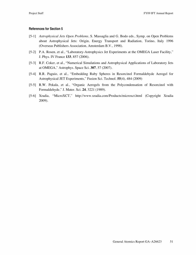
Project Staff FY09 IFT Annual Report
General Atomics Report GA–A26623 51
References for Section 5
[5-1] Astrophysical Jets Open Problems, S. Massaglia and G. Bodo eds., Symp. on Open Problems about Astrophysical Jets: Origin, Energy Transport and Radiation, Torino, Italy 1996 (Overseas Publishers Association, Amsterdam B.V., 1998).
[5-2] P.A. Rosen, et al., “Laboratory-Astrophysics Jet Experiments at the OMEGA Laser Facility,” J. Phys. IV France 133, 857 (2006).
[5-3] R.F. Coker, et al., “Numerical Simulations and Astrophysical Applications of Laboratory Jets at OMEGA,” Astrophys. Space Sci. 307, 57 (2007).
[5-4] R.R. Paguio, et al., “Embedding Ruby Spheres in Resorcinol Formaldehyde Aerogel for Astrophysical JET Experiments,” Fusion Sci. Technol. 55(4), 484 (2009)
[5-5] R.W. Pekala, et al., “Organic Aerogels from the Polycondensation of Resorcinol with Formaldehyde,” J. Mater. Sci. 24, 3221 (1989).
[5-6] Xradia, “MicroXCT,” http://www.xradia.com/Products/microxct.html (Copyright Xradia 2009).

Project Staff FY09 IFT Annual Report
General Atomics Report GA–A26623 53
6. SNL TARGET DEVELOPMENT
6.1. EVOLUTION OF TPX FOAMS FOR HIGHER UNIFORMITY AND DENSITIES
There were also two foam development tasks. The first development task was to produce a three part TPX foam cylinder, 14 mg/cm3, the center section doped with 1 at. % silicon. There were two complications with this foam. First it was small compared to previous foam, only 5.2 mm tall. Since TPX is formed by freezing a solution and then sublimating the solvent away, temperature control is critical to foam quality. The small thermal mass of this foam made it very difficult to build and extract without deformation. The second complication was that SNL requested that we look for a new dopant. We had produced Si doped foams before but the dopant had contains significant oxygen (C30H66O12Si8) and was hydroscopic. The oxygen was not good for spectral studies and the hydroscopic behavior tended to degrade the foam. A new dopant was found, 1,4-Bis (trimethylsilyl) benzene (C12H22Si2). An example of a target foam is shown in Fig. 6-1.
Fig. 6-1. This TPX foam was formed in three sections with the center section having 1 at. % Si. The density of all sections is 14 mg/cm3.
The second foam task was to produce very high density TPX foams, 300 and 600 mg/cm3 in TPX doped foams. The dopant was platinum nanoparticles, 50% by weight in the foam. The actual densities were a bit low, 270 and 520 mg/cm3 but deemed acceptable by the experimenter. The foams were 5 by 5 mm square and diamond turned to 1 mm thickness. The radiographs show uniform foam for the undoped foam and an acceptable particle distribution for the doped foam (Figs. 6-2 and 6-3).
6.2. FY09 MACHINED TARGET R&D WORK FOR SNL
In FY09, we performed a variety of activities in support of development of targets for SNL at GA and at SNL. These cryogenic ICF targets are challenging in terms of machining, assembly and metrology. The metrology in particular involved, cryogenic sealing tests, to ensure gas retentiveness of targets at cryogenic temperatures. We developed such testing capability at GA and performed them in testing of the various targets (Fig. 6-4).

FY09 IFT Annual Report Project Staff
54 General Atomics Report GA–A26623
Fig. 6-2. The image on the left shows two undoped foam squares in an Equation of State panel. To the right is the radiograph showing uniform foam.
Fig. 6-3. The image on the left shows two doped foam squares in a second Equation of State panel. To the right is the radiograph showing uniform particle distribution in the foam.
To allow proper sealing, an epoxy sealing method was initiated which used experience from the work for NIF. However, these sealing methods for Z targets needed to be compatible with foam targets. Each target was thermally cycled five times to verify a leak-free seal. When the fabrication was transferred to SNL the knowledge was also transferred to SNL for onsite fabrication.
In addition to the above, we began development of Be machining for the next generation of Z targets at GA. As shown in (Fig. 6-5), we performed studies to understand tool wear, including examining defects in blanks. By using proper machining parameters we obtained approximately 60 nm surface roughness in Be blanks.
Fig. 6-4. Test stand used to measure the leak rate of different sealing methods at cryogenic temperatures.

Project Staff FY09 IFT Annual Report
General Atomics Report GA–A26623 55
Fig. 6-5. Tool wear from machining Be seen in the difference between (a) a new tool and (b) a worn tool. (c) Bulk defects in machined Be must be understood to achieve a good surface finish.
To further assist in producing predictable machined parts, we developed a software program at GA that allows us to virtually machine targets as shown in (Fig. 6-6). This allowed machining viability testing before loading the lathe program to correct errors before cutting metal. In fact, this predictive capability was put in practice on Lincoln target feasibility tests and allowed the fabrication of these targets.
Fig. 6-6. Test of Lincoln machining program showing the profile in blue and diamond tool path in red.

FY09 IFT Annual Report Project Staff
56 General Atomics Report GA–A26623
Machining tests have been conducted at the request of SNL as well as initiated internally (Fig. 6-7) to produce 3D structures again for future generation of targets at Z.
GA has also applied its coating expertise to SNL targets and R&D prototypes that had multi-layers within the target wall (Fig. 6-8) to produce targets that allowed a new set of experiments.
Fig. 6-7. Test to cut the Lincoln sine wave pattern into 3D screw geometry.
Fig. 6-8. Test of a multi-material wall in which an Au tracer layer was buried in a Cu wall.

Project Staff FY09 IFT Annual Report
General Atomics Report GA–A26623 57
7. PUBLICATIONS AND PRSENTATIONS LIST FY09
7.1. LIST OF PUBLICATIONS
Akli, K.U. and Stephens, R.B, “Laser Heating of Solid Matter by Light-Pressure-Driven Shocks at Ultrarelativistic Intensities,” Phys Rev. Lett. 100, 165002 (2008).
Alexander, N.B., Stephens, R.B., Sweet, W.S., Brown, L.C., Goodin, D.T., and Petzoldt, R.W., “Investigation and Attachment of Polyimide Fill Tubes,” Proc. 18th Topical Meeting on the Technology of Fusion Energy (TOFE), San Francisco, California, 2008, to be published in Fusion Sci. Technol.
Alfonso, E.L., Moreno, K.A., Wilkens, H.L., Jaquez, J.S., Nikroo, A., “Submicron Gold Coating Measurements for Hohlraum Development,” Fusion Sci. Technol. 55, 424 (2009).
Alford, C.S., Cooley, J.C., Cook, R.C., Dixon, L.A., Hackenberg, R.E., Letts, S.A., Moreno, K.A., Alger, E.T., Dzenitis, E.G., Mapoles, E.R., Klingmann, J.L., Bhandarkar, S.D., Reynolds, J.G., Florio, J.W., Lord, D.M., Castro, C., Segraves, K., “Experimental D-T Ice-Layering Target Assembly,” Fusion Sci. Technol. 55, 269 (2009).
Alger, E.T., Dzenitis, E.G., Mapoles, E.R., Klingmann, J.L., Bhandarkar, S.D., Reynolds, J.G., Florio, J.W., Lord, D.M., Castro, C., Segraves, K., “Experimental D-T Ice-Layering Target Assembly,” Fusion Sci. Technol. 55, 269 (2009).
Boehm, K.J., Raffray, A.R., Alexander, N.B., Frey, D.T., and Goodin, D.T., “Numerical and Experimental Analysis of a Fluidized Bed for IFE Target Layering,” Fusion Sci. Technol. 56, 422 (2009).
Bousquet, J.T., Hund, J.F., Goodin, D.T., and Alexander, N.B., “Advancements in Glow Discharge Polymer Coatings for Mass Production,” Fusion Sci. Technol. 55, 446 (2009).
Carlson, L., Tillack, M.S., Stromsoe, J., Alexander, N.B., Goodin, D.T., and Petzoldt, R.W., “Improving the Accuracy of a Target Engagement Demonstration,” Fusion Sci. Technol. 56, 409 (2009).
Chen, C.D., Patel, P.K., Hey, D.S., MacKinnon, A.J., Key, M.H., Akli, K.U., Beg, F.N., Chawla, S., Chen, H., Freeman, R.R., Higginson, D.P., Link, A., Ma, T.Y., MacPhee, A.G., Stephens, R.B., Van Woerkom, L.D., Westover, B., and Porkolab, M., “Bremsstrahlung and Kα Fluorescence Measurements for Inferring Conversion Efficiencies Into Fast Ignition Relevant Hot Electrons,” Phys. Plasmas 16, 082705 (2009).
Chen, H., and Stephens, R.B., “Absolute Calibration of Image Plates for Electrons at Energy Between 100 keV and 4 MeV,” Rev. Sci. Instrum. 79, 033301 (2008).

FY09 IFT Annual Report Project Staff
58 General Atomics Report GA–A26623
Chen, K.C., Nguyen, A.L.Q., Huang, H., Eddinger, S.A., and Nikroo, A., “Update on Germanium-Doped CH Capsule Production for NIF: Scale-Up Issues and Current Yields,” Fusion Sci. Technol. 55, 429 (2009)
Chen, S.N., Gregori, G., Patel, P.K., Chung, H.-K., Kemp, A.J., Le Pape, S., Maddox, B.R., Wilks, S.C., Stephens, R.B., and Beg, F.N., “X-ray Spectroscopy of Buried Layer Foils Irradiated at Laser Intensities in Excess of 1020 W/cm2,” Phys. Plasmas 16, 062701 (2009).
Cook, R.C., Kozioziemski, B.J., Nikroo, A., Wilkens, H.L., Bhandarkar, S., Forsman, A.C., Haan, S.W., Hoppe, M.L., Huang, H., Mapoles, E., Moody, J.D., Sater, J.D., Seugling, R.M., Stephens, R.B., Takagi, M., and Xu, H.W., “National Ignition Facility Target Design and Fabrication,” Laser and Particle Beams 26, 479 (2008).
Dewald, E., Kozioziemski, B.J., Moody, J., Koch, J., Mapoles, E., Montesanti, R., Youngblood, K.P., Letts, S., Nikroo, A., Sater, J., and Atherton, J., “Benchmarking X-ray Phase Contrast Imaging for ICF D-T Ice Characterization Using Roughened Surrogates,” Fusion Sci. Technol. 55, 260 (2009).
Eddinger, S.A., Huang, H., and Schoff, M.E., “Three-Dimensional Wallmapping Using Xradia with Distortion Correction,” Fusion Sci. Technol. 55, 411 (2009)
Fong, J.R., Eddinger, S.A., Huang, H., and Moreno, K.A., “X-ray Absorption Spectroscopy for ICF Target Characterization,” Fusion Sci. Technol. 55, 367 (2009).
Frederick, C.A., Forsman, A.C., Hund, J.F., and Eddinger, S.A., “Fabrication of Ta2P5 Aerogel Targets for Radiation Transport Experiments Using Thin Film Fabrication and Laser Processing,” Fusion Sci. Technol. 55, 499 (2009).
Gibson, C.R., Baltz, J., Malsburay, T., Atkinson, D., Brugmann, V., Coffield, F., Hund, J.F., Paguio, R.R., Schroen, D.G., “Design of the NIF Cryogenic Target System,” Fusion Sci. Technol. 55, 233 (2009).
Goodin, D.T., Hund, J.F., Paguio, R.R., Schroen, D.G., Nikroo, A., Petzoldt, R.W., Alexander, N.B., Carlson, L.C., Tillack, M.S., Boehm, K., Sheliak, J.D., Geller, D.A., Hoffer, J.K., and Flint, G.W., “Wake Shield Target Protection,” Proc. 18th Topical Mtg. on the Technology of Fusion Energy (TOFE), San Francisco, California, 2008, to be published in Fusion Sci. Technol.
Green, J.S., Ovchinnikov, V.M., Evans, R.G., Akli, K.U., Azechi, H., Beg, F.N., Bellei, C., Davies, J.R., Freeman, R.R., Habara, H., Heathcote, R., Key, M.H., King, J.A., Lancaster, K.L., Lopes, N.C., Ma, T., Mackinnon, A.J., Markey, K., McPhee, A., Najmudin, Z., Nilson, P., Norreys, P.A., Onofrei, R., Stephens, R.B., Takeda, K., Tanaka, K.A., Theobald, W., Tanimoto, T., Waugh, J.; VanWoerkom, L., Woosleh, N.C., Zepf, M., “Effect of Laser Intensity on Fast-Electron-Beam Divergence in Solid-Density Plasmas,” Phys. Rev. Lett. 100, 015003 (2008).
Haid, B.J., Malsbury, T.N., Gibson, C.R., Warren, C.T., “Measurement of Total Condensation on a Shrouded Cryogenic Surface Using a Single Quartz Crystal Microbalance,” Fusion Sci. Technol. 55, 276 (2009).
Project Staff FY09 IFT Annual Report
General Atomics Report GA–A26623 59
Haines, M., Wei, M.S., Beg, F.N., and Stephens, R.B., “Hot-Electron Temperature and Laser-Light Absorption in Fast Ignition,” Phys. Rev. Lett. 102, 045008 (2008).
Hoppe, M.L., and Vermillion, B.A., “High-Z Doping of Glass Shells,” Fusion Sci. Technol. 55, 461 (2009).
Huang, H., Eddinger, S.A., and Schoff, M., “Quantitative Dimension Measurement of ICF Components Using Xradia MicroXCT Microscope,” Fusion Sci. Technol. 55, 373 (2009).
Huang, H., Eddinger, S.A., Stephens, R.B., and Nikroo, A., “Quantitative Data Analysis Method for Precision Radiography,” Fusion Sci. Technol. 55, 380 (2009).
Huang, H., Nikroo, A., Stephens, R.B., Eddinger, S.A., Wall, D.R., Moreno, K.A., and Xu, H.W., “Element-Specific Profiling for ICF Ablator Capsules with Mixed Dopant and Impurities,” Fusion Sci. Technol. 55, 356 (2009).
Jaquez, J.S., Nikroo, A., and Wilkens, H.L., “Fabrication and Characterization of Hohlraums with a Co-Mixed Gold-Boron Layer,” Fusion Sci. Technol. 55, 313 (2009).
Johal, Z.Z., Crippen, J.W., Forsman, A.C., Lundgren, E.H., Moreno, K.A., Nikroo, A., “Robust Capsule and Fill Tube Assemblies for the National Ignition Campaign,” Fusion Sci. Technol. 55, 331 (2009).
King, J.A., Akli, K., Freemen, R.R., Green, J., Hatchett, S.P., Hey, M.H., Koch, J.A., Lancaster, K.L., Ma, T., MacKinnon, A.J., MacPhee, A., Norreys, P.A., Patel, P.K., Phillips, T., Stephens, R.B., Theobald, W., Town, R.P.J., van Woerkom, L., Zhang, B., and Beg, F.N., “Studies on the Transport of High Intensity Laser-Generated Hot Electrons in Cone Coupled Wire Targets,” Phys. Plasmas 16, 020701 (2009).
Kuranz, C.C., Drake, R.P., Grosskopf, M.J., Budde, A., Krauland, C., Marion, D.C., Visco, A.J., Ditmar, J.R., Robey, H.F., Remington, B.A., Miles, A.R., Cooper, A.B.R., Sorce, C., Plewa, T., Hearn, N.C., Killebrew, K.L., Knauer, J.P., Arnett, D., and Donajkowski, T.L., “Three-dimensional Blast-wave-driven Rayleigh-Taylor Instability and the Effects of Long-Wavelength Modes,” Phys. Plasmas 16, 056310 (2009).
Le Pape, S., Tsu, Y.-Y., MacPhee, A., Hey, D., Patek, P., MacKinnon, A., Key, M., Wei, M.-S., Ma, T., Beg, F.N., Stephens, R., Akli, K., Link, T., Van Woerkom, L., and Freeman, R.R., “Characterization of the Preformed Plasma for High-Intensity Laser-Plasma Interaction,” Opt. Lett. 34, 2997 (2009).
Lee, Y.T., Johnson, M.A., Nikroo, A., Montesanti, R.C., Huang, H., Moreno, K.A., Chen, K.C., Chen, C., and Nguyen, A.Q.L., “Increasing the Throughput of Phase-Shifting Diffraction Interferometer for Quantitative Characterization of ICF Ablator Capsule Surfaces,” Fusion Sci. Technol. 55, 405 (2009).

FY09 IFT Annual Report Project Staff
60 General Atomics Report GA–A26623
Li, C.K., Seguin, F.H., Rygg, J.R., Frenje, J.A., Manuel, M., Petrasso, R.D., Betti, R., Delettrez, J., Knauer, J.P., Marshall, F., Meyerhofer, D.D., Shvarts, D., Smalyuk, V.A., Stoeckl, C., Landen, O.L., Town, R.P.J., Back, C.A., and Kilkenny, J.D., “Monoenergetic-Proton-Radiography Measurements of Implosion Dynamics in Direct-Drive Inertial-Confinement Fusion,” Phys. Rev. Lett. 100, 225001 (2008).
Lundgren, E.H., and Forsman, A.C., “Laser Forming of Shaped Fill Holes in Beryllium Targets for Inertial Confinement Fusion Experiments,” Fusion Sci. Technol. 55, 325 (2009).
Luo, R.W., Greenwood, A.L., Nikroo, A., and Chen, C., “Properties of Silicon-Doped GDP Shells Used for Cryogenic Implosions at OMEGA,” Fusion Sci. Technol. 55, 456 (2009).
Ma, T., Beg, F.N., MacPhee, A.G., Chung, H.-K., Key, M.H., MacKinnon, A.J., Patel, P.K., Hatchett, S., Akli, K.U., Stephens, R.B., Chen, C.D., Freeman, R.R., Link, A., Offermann, D.T., Ovchinnikov, V., and Van Woerkom, L.D., “Electron Heated Target Temperature Measurements in Petawatt Laser Experiments Based on Extreme Ultraviolet Imaging and Spectroscopy,” Rev. Sci. Instrum. 79, 10E312 (2008).
Ma, T., Key, M.H., Mason, R.J., Akli, K.U., Daskalova, R.L., Freeman, R.R., Green, J.S., Highbarger, K., Jaanimagi, P.A., King, J.A., Lancaster, K.L., Hatachett, S.P., MacKinnon, A.J., MacPhee, A.G., Norreys, P.A., Patel, P.K., Stephens, R.B., Theobald, W., Van Woerkom, L.D., Wei, M.S., Wilks, S.C., and Beg, F.N., “Transport of Energy by Ultraintense Laser-Generated Electrons in Nail-wire Targets,” Phys. Plasmas 16, 112702 (2009).
Mason, R.J., Faehl, R., Kirkpatrick, R., Ma, T., Wei, M.S., Beg, F.N., Key, M.H., and Stephens, R.B., “ePLAS Modeling of Hot Electron Transport in Nail-Wire Targets,” submitted to Nucl. Fusion, 2009.
Monstesanti, R.M., Seugling, R.M., Klingmann, J.L., Dzenitis, E.G., Alger, E.T., Miller, G.L., Kent, R.A., Castro, C., Reynolds, J.L., and Carrillo, M.A., “Robotic System for Precision Assembly off NIF Ignition Targets,” Proc. of the American Society for Precision Engineering 2008 Annual Meeting, Portland, Oregon (2008).
Moreno, K.A., Eddinger, S.A., Fong, J.R., Lee, Y.T., Nguyen, A.Q.L., Nikroo, A., Huang, H., Rosano, R., and Xu, H.W., “Overview of National Ignition Facility Capsule Metrology,” Fusion Sci. Technol. 55, 349 (2009).
Nguyen, A.L., Eddinger, S.A., Huang, H., Lee, Y.T., Moreno, K.A., Schoff, M.E., “Characterization of Isolated Defects for NIF Targets Using PSDI with an Analysis of Shell Flipping Capability,” Fusion Sci. Technol. 55, 399 (2009).
Paguio, R.R., Frederick, C.A., Havsky, J., Hund, J.F., Nikroo, A., Thi, M.A., “Br Surface Chemistry and Corrosion on Pt(111) Surface,” in Grazing-Incidence Small-Angle X-Ray Scattering, edited by B. Ocko, J. Wang, K. Ludwig, T.P. Russell (Mater. Res. Soc. Symp. Proc. Volume 1147E, Warrendale, PA, 2009), paper 1147-OO04-05.

Project Staff FY09 IFT Annual Report
General Atomics Report GA–A26623 61
Paguio, R.R., Hund, J.R., Blue, B.E., Schroen, D.G., Saito, K.M., Frederick, C.A., Strauser, R.J., and Quan, K., “Embedding Sapphire Spheres in Resorcinol Formaldehyde Aerogel for Astrophysical Jet Experiments,” Fusion Sci. Technol. 55, 490 (2009).
Paguio, R.R., Nikroo, A., Saito, J.M., Hund, J.R., Castillo, E.R., Ravelo, N.M., and Quan, K., “Improvements on Permeation GDP Coatings for Resorcinol Formaldehyde Foam Shells for Cryogenic Experiments on OMEGA,” Fusion Sci. Technol. 55, 450 (2009).
Pasley, J., and Stephens, R.B., “Experimental Observations of Transport of Picosecond Laser Generated Electrons in a Nail-Like Target,” IEEE Transactions on Plasma Science (2008).
Peterson, B.M., DeFriend, K.A., Havrilla, G.J., Nikroo, A., and Huang, H., “Nondestructive Investigations of a Copper- and Argon-Doped Sputtered Beryllium Capsule Using X-rays in Three Dimensions,” Fusion Sci. Technol. 55, 417 (2009).
Petzoldt, R.W., Carlson, L.C., Hares, J.D., and Stromose, J., “Target Steering and Electrostatic Acceleration for IFE,” Proc. 23rd Symposium on Fusion Engineering (SOFE), San Diego, California, 2009, to be published in IEEE Transactions on Plasma Science (2009).
Petzoldt, R.W., Valmianski, E.I., Carlson, L.C., Stromose, J., Hares, J.D., “Target Injection with Electrostatic Acceleration,” Fusion Sci. Technol. 56, 417 (2009).
Saito, K.M., Hund, J.F., Paguio, R.R., Nikroo, A., Crippen, J.W., Johal, Z.Z., “Fill Tube Assembly Development for Omega and NIF Shell Applications,” Fusion Sci. Technol. 55, 337 (2009).
Sheliak, J.D., Geller, D.A., Hoffer, J.K., “Oxygen Induced Missing Row Reconstruction on Mo(001) (2x1) Studied by STM,” Proc. 18th Topical Meeting on the Technology of Fusion Energy (TOFE), San Francisco, California, 2008, to be published in Fusion Sci. Technol.
Stephens, R.B., Akli, K.U., Bartel, T., Beg, F.N., Chawla, S., Chen, C.D., Chen, H., Chen, S., Chrisman, B., Freeman, R.R., Hey, D., Key, M., Kemp, A., King, J., Lancaster, K., LePape, S., Link, A., Ma, T., MacKinnon, A.J., MacPhee, A.G., Norreys, P., Offerman, D., Ovchinnikov, V., Pasley, J., Patel, P., Schumacher, D., Sentoku, Y., Tsui, Y., Wilks, S., Van Woerkom, L.D., Wei, M.S., and Yabuuchi, T., “Energy Injection for Fast Ignition,” Plasma and Fusion Research, Review Articles 4, 016 (2009).
Stephens, R.B., Akli, K.U., Bartel, T., Beg, F.N., Chawla, S., Chen, C.D., Divol, L., Fedosejevs, R., Freeman R.R., Friesen, H., Giraldez, E., Hey, D.S., Higginson, D.P., Jarrot, C., Kemp, G.E., Key, M.H., Krygier, A., Larson, D., Le Pape, S., Link, A., Ma, T.Y., MacKinnon, A.J., MacLean, H.S., MacPhee, A.G., Murphy, C., Ovchinnikov, V., Patel, P.K., Ping, Y., Sawada, H., Schumacher, D., Tsui, Y., Turnbull, D., Wei, M.S., Van Woerkom, L.D., Westover, B., Wilks, S.C., Yabuuchi, T., “Divergence of Laser-Generated Hot Electrons Produced in a Cone Geometry,” accepted for publication in J. Phys. Conf. Ser., 2009.

FY09 IFT Annual Report Project Staff
62 General Atomics Report GA–A26623
Stephens, R.B., Alexander, N.B., Brown, L.C., Goodin, D.T., Petzoldt, R.W., Sweet, W.S., “Cs Adsorption on Si(001) 2x1 Studied by STM, LEED/AES,” Proc. 18th Topical Meeting on the Technology of Fusion Energy (TOFE), San Francisco, California, 2008, to be published in Fusion Sci. Technol.
Stephens, R.B., MacKinnon, A.J., Offerman, D., Akli, K.U., Bartel, T., Beg, F.N., Chawla, S., Chen, C.D., Clark, D., Freeman, R.R., Hey, D.S., Key, M.H., King, J.A., Link, A., Ma, T., MacPhee, A.G., Ovchinnikov, V.M., Ping, Y., Tsui, Y., Wei, M.S., and Van Woerkom, L.D., “Co Cluster Growth and Induced Surface Morphology Changes on HOPG Studied by STM,” Proc. of Int. Conf. on HEDP/HEDLA-08, St. Louis, Missouri, 2008, to be published in Astrophys. and Space Sci. 307 (2008).
Tampo, T., Awano, S., Bolton, P.R., Kondo, K., Mima, K., Mori, Y., Nakamura, H., Nakatsutsumi, M., Stephens, R.B., Tanaka, K.H., Tanimoto, T., Yabuuchi, T., and Kodama, R., “Correlations Between MeV Proton and Electron Beam Generated in Ultra-Intense Laser Plasma Interactions,” submitted to Phys. Plasmas, 2009.
Tanimoto, T., Habara, H., Kodama, R., Nakatsutsumi, M., Lancaster, K.L., Green, J.S., Scott, R.H.H., Sherlock, M., Norreys, P.A., Evans, R.G., Haines, M.G., Kar, S., Zepf, M., King, J., Ma, T., Wei, M.S., Yabuuchi, T., Beg, F.N., Key, M.H., Nilson, P., Stephens, R.B., Azechi, H., Nagai, K., Norimatsu, T., Takeda, K., Valente, J., and Davies, J.R., “Measurements off Fast Electron Scaling Generated by Petawatt Laser Systems,” Phys. Plasmas 16, 062703 (2009).
Theobald, W., Anderson, K.S., Betti, R., Craxton, R.S., Delettrez, J.A., Frenje, J.A., Glebov, V.Yu., Gotchev, O.V., Kelly, J.H., Li, C.K., MacKinnon, A.J., Marshall, F.J., McCrory, R.L., Meyerhofer, D.D., Myatt, J.F., Norreys, P.A., Nilson, P.M., Patel, P.K., Petrasso, R.D., Radha, P.B., Ren, C., Sangster, T.C., Seka, W., Smalyuk, V.A., Solodov, A.A., Stephens, R.B., Stoeckl, C., and Yaakobi, B., “Advanced-Ignition-Concept Exploration on OMEGA,” Plasma Phys. Control. Fusion 51, 124052 (2009).
Theobald, W., Stoeckl, C., Jaanimagi, P., Nilson, P., Storm, M., Meyerhofer, D.D., Sangster, T.C., Hey, D., MacKinnon, A.J., Park, H.-S., Patel, P., Shepherd, R., Snavely, R., Key, M., King, J.A., Zhang, B., Stephens, R.B., Akli, K., Highbarger, K., Weber, R., Van Woerkom, L., Freeman, R.R., Green, J., Gregori, G., Lancaster, K., and Norreys, P.A., “A Dual-Channel, Curved-Crystal Spectrograph for Petawatt-Laser X-ray Backlighter,” submitted to Rev. Sci. Instrum., 2009.
Wei, M.S., Solodov, A.A., Pasley, J., Stephens, R.B., Welch, D.R., and Beg, F.N., “Study of Relativistic Electron Beam Production and Transport in High-Intensity Laser Interaction with a Wire Target by Integrated LSP Modeling,” Phys. Plasmas 15, 083101 (2008).

Project Staff FY09 IFT Annual Report
General Atomics Report GA–A26623 63
7.2. LIST OF PRESENTATIONS
13th Intl. Workshop on Radiative Properties of Hot Dense Matter, Santa Barbara, California, November 10, 2008:
• C. Back, “Exploring Novel Physics in the Laboratory Using Low Density Materials.”
50th APS Meeting of the Div. of Plasma Physics, Dallas, Texas, November 17, 2008:
• B. Blue, “Shock-Clump Interaction Studies in the Laboratory.”
• S. Eddinger, “Creating a Precision Optical Depth Uniformity Tool for ICF Targets.”
• S. Eddinger, “Creating a Precision Optical Depth Uniformity Tool for ICF Targets.”
• R. Paguio, “Fabrication of HAPL Sized R/F foam Shells — (IFE Target Fabrication Update).”
• R. Stephens, “Electron Generation in Fast Ignition Targets.”
19th HAPL Workshop, Madison, Wisconsin, October 22, 2008:
• J. Hund, “Droplet Microfluidics and Target Fabrication.”
• J. Hund, “Progress on HAPL Foam Capsule and Overcoat Fabrication.”
2nd European Target Fabrication Conference, United Kingdom, October 27, 2008:
• J. Hund, J., “Target Technologies: Foams, Capsules and Target Insertion.”
• R. Paguio, “Fabrication of HAPL Sized R/F foam Shells — (IFE Target Fabrication Update).”
Materials Research Society, Fall Meeting, Boston, Massachusetts, December 1, 2008:
• R. Paguio, “Modifying the Pore Size of Resorcinol Formaldehyde Aerogels for Fabrication of Hollow Spheres for Direct Drive ICF Experiments.”
Physics and Astronomy Colloquium, California State University, Long Beach, California, October 6, 2008:
• H. Wilkens, “Sputtered Depleted Uranium for Applications in Inertial Confinement Fusion.”
SHGR Quarterly Meeting, Las Vegas, Nevada, January 22, 2009:
• L. Brown, “Solar Adaptation of the Sulfur-Iodine Thermochemical Cycle.”
• B. Wong, “Solar Cadmium Hydrogen Production Cycle — Progress Report.”
Foam Workshop, General Atomics , San Diego, California, January 26, 2009:
• N. Alexander, “Basis for Selecting a Fluidized Bed for Layering of Inertial Fusion Energy Targets.”
• L. Brown, “Novel Unsealed Foam Capsule Coating.”

FY09 IFT Annual Report Project Staff
64 General Atomics Report GA–A26623
• L. Brown, “Survey of Alternative Coating Methods for Overcoating Foam Shells.”
• J. Hund, “Status of Baseline Foam Technique: Fluid Systems, Chemistries, Pore Size, and Measurement Techniques.”
• R. Petzoldt, “Behavior During Injection for a Cryogenic Gas Overcoat System.”
General Atomics, February 11, 2009:
• B. Russ, “GA Hydrogen and Clean Energy Process Development.”
DARPA, Washington, DC, March 3, 2009:
• R. Stephens, “Plasma-Surface Interactions at General Atomics.”
National Hydrogen Association Meeting, Columbia, South Carolina, March 31, 2009:
• B. Russ, “ILS Status.”
• B. Wong, “Solar Cadmium Hydrogen Production Cycle.”
LIFE Project Meeting, Lawrence Livermore National Laboratory, March 31, 2009:
• G. Flint, “Tracking and Engagement of LIFE Targets.”
• R. Petzoldt, “Induction Accelerator Design Progress.”
OMEGA User's Group Meeting; University of Rochester, Rochester, New York, April 29, 2009:
• B. Vermillion, “General Atomics Inertial Fusion Technology (IFT) Partners in the Target Fabrication Community.”
STCH Quarterly Meeting, Sandia National Laboratory, May 6, 2009:
• L. Brown, “Cadmium Quench – Single Droplet Models.”
• B. Russ, “Sulfur Iodine Program Status.”
23rd Symp. on Fusion Engineering (SOFE), San Diego, California, May 31, 2009:
• N. Alexander, “A Target Fielding System for the Gemini, Rep-Rated High-Power Laser.”
• J. Hund, “Fabricating Foam Capsules for Direct Drive IFE.”
• R. Petzoldt, “Target Steering and Electrostatic Acceleration for IFE.”
ICOPS Mini-Course Instructor, San Diego, California, June 5, 2009:
• K. Akli, “Self-emission Probing of Laser-Produced Plasmas.”
• N. Alexander, “Targets for Rep-Rated Laser Facilities.”
• B. Blue, “Transforming Outer Space into the Laboratory: Fabrication of Astrophysically Relevant Targets.”

Project Staff FY09 IFT Annual Report
General Atomics Report GA–A26623 65
• H. Huang, “Metrology Development for ICF and HED Targets.”
• J. Hund, “Low Density Limits in Target Fab.”
• M. Mauldin, “Real World Target Structure and its Control.”
• R. Stephens, “Target Fabrication for High Energy Density Physics.”
NIF Capsule Meeting at Lawrence Livermore National Laboratory, June 5, 2009:
• K. Moreno, “Update on CH Isolated Defects.”
Hydrogen Down Selection Meeting, Denver, Colorado, June 23, 2009:
• B. Russ, “SI Process Review.”
Lawrence Livermore National Laboratory, July 9, 2009:
• K. Moreno, “Update on CH Isolated Defects 2.”
Thermochemical Heat Storage Project Meeting, San Diego, California, July 17, 2009:
• R. Buckingham, L. Brown, “HS Flowsheet Economics.”
• B. Wong, “Thermochemical Heat Storage for Concentrated Solar Power.”
HED Summer School, University of California-Los Angeles, July 29, 2009:
• R. Stephens, “HED Opportunities at GA.”
University of California-Los Angeles, August 1, 2009:
• R. Stephens, “GA plans for FSC.”
UNLV Renewable Energy Symp., Las Vegas, Nevada, August 11, 2009:
• L. Brown, “Solar Based Thermochemical Cycles Based on Sulfur.”
6th Intl. Conf. on Inertial Fusion Sciences and Applications, San Francisco, California, September 6, 2009:
• K. Akli, “Hot-Electron Generation and Transport Using Ka Emission.”
• B. Blue, “Laboratory Astrophysics: Challenges in Design and Target Fabrication.”
• K. Moreno, “Update of Capsule Fabrication and Characterization for the National Ignition Facility.”
• A. Nikroo, “Fabrication and Characterization of AuB Lined Hohlraums.”
• R. Stephens, “Anomalous Divergence of Laser-Generated Hot Electrons Generated in a Cone Geometry.”

FY09 IFT Annual Report Project Staff
66 General Atomics Report GA–A26623
SolarPaces 2009, Berlin, Germany, September 15, 2009:
• L. Brown, “Multivalent Metal Oxides for Thermochemical Energy Storage.”
ReNew Workshop, Washington, DC, October 6, 2009:
• C. Back, “EM2 Fuel.”