Industry Terminal User/Service Manual 0507.pdf · Industry Terminal User/Service Manual METTLER...
24
IND221 IND226 Industry Terminal User/Service Manual METTLER TOLEDO 182837 (2006-2-8)
Transcript of Industry Terminal User/Service Manual 0507.pdf · Industry Terminal User/Service Manual METTLER...

IND221
IND226 Industry Terminal
User/Service Manual
METTLER TOLEDO 182837 (2006-2-8)

PRECAUTIONS
WARNING
DISCONNECT ALL POWER TO THIS UNIT BEFORE INSTALLING, SERVICING, CLEANING, OR REMOVING THE FUSE. FAILURE TO DO SO COULD RESULT IN BODILY HARM AND/OR PROPERTY DAMAGE.
CAUTION
OBSERVE PRECAUTIONS FOR HANDLING
ELECTROSTATIC SENSITIVE DEVICES.
WARNING ONLY PERMIT QUALIFIED PERSONNEL TO SERVICE THIS EQUIPMENT. EXERCISE CARE WHEN MAKING CHECKS, TESTS AND ADJUSTMENTS THAT MUST BE MADE WITH POWER ON. FAILING TO OBSERVE THESE PRECAUTIONS CAN RESULT IN BODILY HARM.
WARNING
FOR CONTINUED PROTECTION AGAINST SHOCK HAZARD, CONNECT TO PROPERLY GROUNDED OUTLET ONLY. DO NOT REMOVE THE GROUND PRONG.
READ this manual BEFORE operating or servicing this equipment. FOLLOW these instructions carefully. SAVE this manual for future reference. DO NOT allow untrained personnel to operate, clean, inspect, maintain, service, or tamper with this equipment. ALWAYS DISCONNECT this equipment from the power source before cleaning or performing maintenance.
Note: If the unit has been stored or
transported in below freezing
temperatures, allow the unit to warm
up to room temperature before turning
on AC power.

CAUTION
BEFORE CONNECTING OR DISCONNECTING ANY INTERNAL ELECTRONIC COMPONENTS OR
INTERCONNECTING WIRING BETWEEN ELECTRONIC EQUIPMENT, ALWAYS REMOVE POWER
AND WAIT AT LEAST THIRTY (30) SECONDS BEFORE ANY CONNECTIONS OR
DISCONNECTION’S ARE MADE. FAILURE TO OBSERVE THESE PRECAUTIONS COULD RESULT
IN DAMAGE TO OR DESTRUCTION OF THE EQUIPMENT, OR BODILY HARM.
CAUTION
THE IND226 SOCKET-OUTLET SHALL BE INSTALLED NEAR THE EQUIPMENT AND SHALL BE
EASILY ACCESSIBLE.
CAUTION
RISK OF EXPLOSION IF BATTERY IS REPLACED BY EN INCORRECT TYPE. DISPOSE OF USED
BATTERIES ACCORDING TO THE INSTRUCTIONS
CAUTION
REPLACE THE FUSES ONLY BY SERVICE PERSONNEL


Contents
1.0 Overview................................................................................................................................. 1 1.1 Specification ....................................................................................................................... 1 1.2 Main functions .................................................................................................................... 1 1.3 Dimensions ......................................................................................................................... 2 1.4 Order information ............................................................................................................... 2
2.0 Install ...................................................................................................................................... 3 2.1 Open the package................................................................................................................ 3 2.2 Electronic Connect.............................................................................................................. 3
2.2.1 Open the terminal.................................................................................................... 3 2.2.2 Load Cell Connect .................................................................................................. 3 2.2.3 Com1 RS232........................................................................................................... 4
2.3 Lead seal ............................................................................................................................. 5 2.4 Battery Pack Option............................................................................................................ 5
2.4.1 Battery install .......................................................................................................... 5 2.4.2 Recharge Battery..................................................................................................... 6 2.4.3 Use Battery.............................................................................................................. 6
3.0 Operation ................................................................................................................................ 7 3.1 Operation HMI.................................................................................................................... 7 3.2 Basic function operation ..................................................................................................... 7
3.2.1 On/Off key .............................................................................................................. 7 3.2.2 Zero ......................................................................................................................... 7 3.2.3 Tare ......................................................................................................................... 7 3.2.4 Clear........................................................................................................................ 8 3.2.5 Print......................................................................................................................... 8
3.3 Expand functions ................................................................................................................ 8 3.3.1 X10 Function .......................................................................................................... 8 3.3.2 Unit switch .............................................................................................................. 8 3.3.3 Over/Under Function .............................................................................................. 8 3.3.4 Counting Function................................................................................................. 10
4.0 Setup ..................................................................................................................................... 11 4.1 Enter Setup........................................................................................................................ 11 4.2 Keys in setup..................................................................................................................... 11 4.3 Setup Detail......................................................................................................................... 9
5.0 Terminal Maintenance........................................................................................................... 15 5.1 Daily maintenance ............................................................................................................ 15 5.2 Error Messages.................................................................................................................. 15 5.3 Software download ........................................................................................................... 16

1
1.0 Overview
1.1 Specification
6 digits 1.2” large green LED display. Robust long life. 6 Function keys, Simple and easy. IND221: Plastic, Protection IP54. IND226: Stainless steel, Protection: IP69K. Executive voltage:+5VDC. Load Cell capability: Maximum 4-350ohm analog load cell. Zero signal input ranges: 0~5mV. SPAN signal input ranges: 1~10mV. Resolution: 1,000,000. Increments: 1,000 ~ 30,000 A/D Rates: 27 /seconds. Working voltage: AC87~264VAC, 0.1A
DC: NI-HM rechargeable battery (Optional) DC: C Size Dry Battery(Optional)
RS232 Serial port Working temperature: -10°C - +40°C, Relative Humidity < 85%. Storage temperature: -20°C - +60°C, Relative Humidity < 85%.
1.2 Main functions
Basic weighing: Zero, Tare, Clear, Print. Auto print function. Units switch: kg,lb. x10 function / Simple check weighing / Counting. English/Chinese print formats. Support ticket micro printer. Power saving technology. Low battery icon. Auto power off.

2
1.3 Dimensions
150mm
220mm
129.1mm
136.8mm
1.590°
45°
IND221
150mm
220mm
132mm
90mm
66mm
IND226
1.4 Order information
Model Name Descriptions P/N IND221-1000 Plastic Standard(with dry case) 72183995 IND221-1001 Plastic With rechargeable battery 72183997 IND226-1000 Harsh, Standard 72183987
IND226-1001 Harsh, With rechargeable battery 72183989

3
2.0 Install
This part will talking about the Installation for IND221 and IND226. Please read this chapter carefully before install.
2.1 Open the package
Open the package, And check all the parts with the checklist. Make sure no part was damaged and missing. Remove the terminal from its protective package, .
2.2 Electronic Connect
2.2.1 Open the terminal The IND221 terminal use 4 screws to lock the front cover. The front panel of the IND226 terminal is locked in place by four spring clips attached
to the enclosure body. To gain access to the terminal’s PCB for internal wiring and setting switches, separate the front panel from the enclosure as follows:
Insert the tip of a flat-blade screwdriver into one of the two slots located on the bottom of the front panel assembly and gently push in toward the enclosure. A “pop” sound is made when the cover is released.
2.2.2 Load Cell Connect 7 Pins terminal strip. Pin 1 - +EXC Pin 2 - +SEN Pin 3 - +SIG Pin 4 - Shield
1
+EX
C+S
EN+S
IGSh
ield
-SIG
-SEN
-EX
C

4
Pin 5 - -SIG Pin 6 - -SEN Pin 7 - -EXC
For 4 wires load cell, you should short the W1 two pins, and short the W2 two pins in PCB.
IND221 use PG9 cable bush grip, the allow cable diameter is 4 to 9mm. IND226 use PG11 cable bush grip, the allow cable diameter is 5 to 10mm. We recommend use CMX or CM cables for load cell connect. The cable information: Type: CMX, CM Parameter: 6x0.2mm2
Voltage: Max. 380V Temperature range: -30~+80°
Cable diam: 6.1±0.15mm.
Isolation material: UBEC180 polyethylene.
Protection jacket: 90°C HZ-90(318#)
2.2.3 Com1 RS232
IND221: RS232 use D-Sub Male connector Pin 2 - RXD Pin 3 - TXD Pin 5 - GND
IND226: Serial port use 3 Pins terminal strip. Pin 1 - TXD Pin 2 - RXD Pin 3 - GND
1
2
3
2
3
5
IN D226 C omputerD B9
1
TXD
RX
DG
ND
1 2 3 4 5
6 7 8 9
5
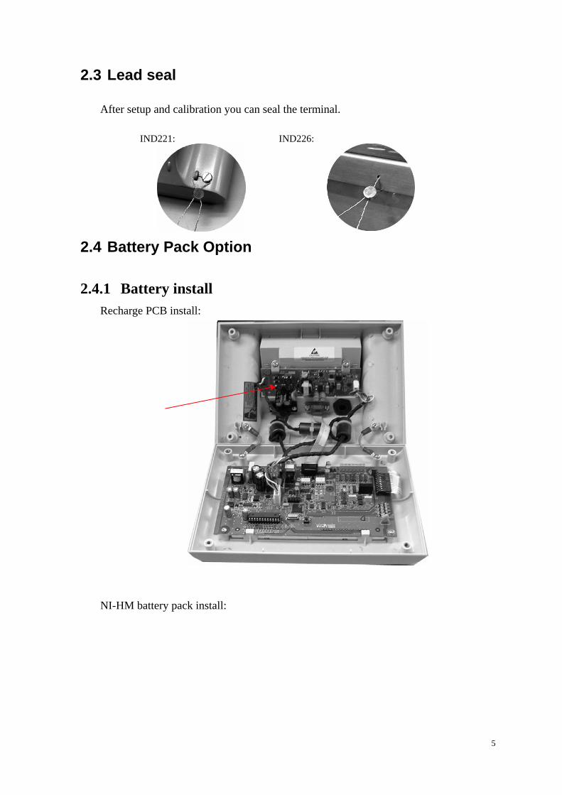
2.3 Lead seal
After setup and calibration you can seal the terminal. IND221: IND226:
2.4 Battery Pack Option
2.4.1 Battery install Recharge PCB install:
NI-HM battery pack install:

6
2.4.2 Recharge Battery When the low battery cursor light on red color, it means the battery voltage is low, you
can still continuous your work for about one hour.. When the low battery cursor flash on red color, it means the battery voltage is too low,
you should charge the battery immediately. Plug the AC power line will automatic recharge the battery, and the low battery cursor
will light on green color. Normally the charge time is about 12 hours. For new terminal, please charge the battery for 12 hours before use the battery.
2.4.3 Use Battery Full charged battery can continuous work 35 hours. The following setup can longer the work hour.:
Set timeout (F3.1.1), When the scale hasn’t operate for certain time, the terminal will automatic turn off the display. Only kg cursor light. And when the scale add weight or press any key. The terminal will automatically turn on the display.
Set brightness to low (F3.1.2). When the terminal use battery, the display brightness will turn to low, when use AC power, the display brightness will automatically change to high.
Set Auto power off(F3.2), When the scale haven’t any operation in certain times, the terminal will automatically power off.

7
3.0 Operation
3.1 Operation HMI
METTLER TOLEDO
0 F C
Under OK Over NET >|1|< >|2|< lb kg
On/Off Zero Tare Function Clear Print
BatteryUnits
Ranges
FunctionMotion
Net
T
“Under OK Over” is use for check weighing. You can stick ”Count APW PCS” label for counting function.
3.2 Basic function operation
3.2.1 On/Off key Hold the key 2 seconds, All display segments will light. The terminal will show software part number [178037] [L 1.00]. Then the terminal will show the normal weight. In normal display state, Hold this key 2 seconds, the terminal will show [ -OFF- ], then power off.
3.2.2 Zero Zero the scale.
3.2.3 Tare Tare the scale, the display will change to Net mode..
0
T

8
3.2.4 Clear Clear the tare, the display will go back to gross mode.
3.2.5 Print Print the current weight.
3.3 Expand functions
3.3.1 X10 Function F2.1 is set to ÑÖUL10 - x10 function.
Press F
key, The terminal will show
more accuracy weight for 20 seconds. Print is forbidden in this mode.
3.3.2 Unit switch F2.1 is set to Unit – Unit switch
Press F
key, you can switch the weight
units at kg or lb.
3.3.3 Over/Under Function F2.1 is set to OVEr - Over/Under function
F2.1.1 is set to CHECh - Check weighing mode. Target weight setting:
Press F
key to switch Over/Under mode.
Hold F
key for 2 seconds. Or you can
press Tare key to tare the weight.
Under OK Over NET >|1|< >|2|< lb kg
Under OK Over NET >|1|< >|2|< lb kg
Under OK Over NET >|1|< >|2|< lb kg
Count APW PCS NET >|1|< >|2|< lb kg
Under OK Over NET >|1|< >|2|< lb kg
Under OK Over NET >|1|< >|2|< lb kg
C

9
The terminal show the old target weight.. If F2.2.2 is set to WEIGHt- Get target weight from weighing. Then you can put the target
weight in scale platform. Press F
key to
set new target weight. If F2.2.2 is set to MAnUAL- Manually set the target weight. You can input target weight directly, then press Enter to confirm.
Operation: Current weight less than target weight and over tolerance. Current weight near the target weight and within tolerance. Current weight larger than target weight and over tolerance.
F2.1.1 is set to CLASS- Classifying mode. Target weight setting:
Press F
key to switch Over/Under mode.
Hold F
key for 2 seconds. Or you can
press Tare key to tare the weight. The terminal show the old target weight.. If F2.2.2 is set to WEIGHt- Get target weight from weighing. Then you can put the target
weight in scale platform. Press F
key to
set new target weight. If F2.2.2 is set to MAnUAL- Manually set the target weight. You can input target weight
Under OK Over NET >|1|< >|2|< lb kg
Under OK Over NET >|1|< >|2|< lb kg
Under OK Over NET >|1|< >|2|< lb kg
Under OK Over NET >|1|< >|2|< lb kg
Under OK Over NET >|1|< >|2|< lb kg
Under OK Over NET >|1|< >|2|< lb kg
Under OK Over NET >|1|< >|2|< lb kg
Under OK Over NET >|1|< >|2|< lb kg
Under OK Over NET >|1|< >|2|< lb kg

10
directly, then press Enter to confirm. Operation:
Current weight less than target weight and over tolerance. Current weight near the target weight and within tolerance. Current weight larger than target weight and over tolerance.
3.3.4 Counting Function F2.1 is set to Count - Counting function. Stick “Count APW PCS” label at “Under OK Over” position. Display Mode switch:
Normal display mode.
Press F
key to switch counting PCS
mode, show current pieces.
Press F
key to switch counting APW
mode, show average piece weight.
Sampling:
Hold F
key 2 seconds. Or you can press
Tare key to tare the weight.
Press F
key to select sample pieces:
5,10,20,50. Put the sample pieces on scale platform, press Enter to confirm.
Under OK Over NET >|1|< >|2|< lb kg
Under OK Over NET >|1|< >|2|< lb kg
Under OK Over NET >|1|< >|2|< lb kg
Count APW PCS NET >|1|< >|2|< lb kg
Count APW PCS NET >|1|< >|2|< lb kg
Count APW PCS NET >|1|< >|2|< lb kg
Count APW PCS NET >|1|< >|2|< lb kg
Count APW PCS NET >|1|< >|2|< lb kg
Count APW PCS NET >|1|< >|2|< lb kg
11
Display mode will go back to counting PCS mode.
APW Enhancement: If F2.3 = On, Enable APW enhancement function. Then after the pieces number increased, the terminal will automatically adjust the average weight to get more accuracy pieces number.
4.0 Setup
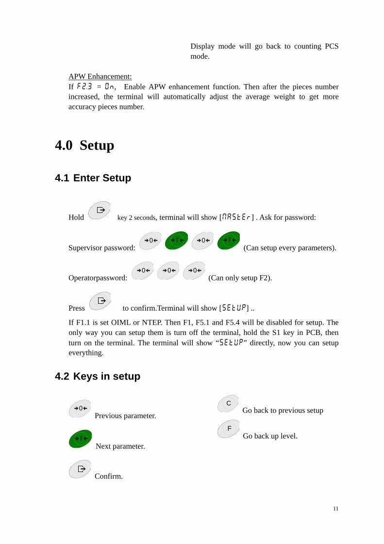
4.1 Enter Setup
Hold key 2 seconds, terminal will show [MAStEr] . Ask for password:
Supervisor password: 0
T
0
T
(Can setup every parameters).
Operatorpassword: 0
0
0
(Can only setup F2).
Press to confirm.Terminal will show [SEtUp] ..
If F1.1 is set OIML or NTEP. Then F1, F5.1 and F5.4 will be disabled for setup. The only way you can setup them is turn off the terminal, hold the S1 key in PCB, then turn on the terminal. The terminal will show “SEtUp” directly, now you can setup everything.
4.2 Keys in setup
0 Previous parameter.
T Next parameter.
Confirm.
C Go back to previous setup
F Go back up level.

9
Digits Input: Press F
key to edit current number. Change input cursor to left.
Press C
key to clear current number.
Press 0
key to decrease. PressT
key to increase.
Press to confirm..
4.3 Setup Detail
F1 – Scale
F1.1 – Approval
Selection: no(Factory default) - none OIÑÖL - OIML ntEP - NTEP otHEr - Other approval
F1.2 – Scale Capacity & Increments F1.2.1 – Units Selection: 1 - kg (Factory default) 2 - lb F1.2.2 – Ranges Selection: 1 r – 1 Range (Factory default) 2 r - 2 Ranges F1.2.3 – Capacity (First Range) Selection: 3 … 20’000 (Factory default 6)
F1.2.4 – Increments (First Range)
Selection: 0.0001 ~ 10 (Factory default 0.001) F1.2.5 – Capacity (Second Range)
Selection: 3 … 20’000 (Factory default 3) Notes: Capacity (Second Range) should less than Increments (First Range). F1.2.6 –Increments (Second Range)
Selection: 0.0001 ~ 10 (Factory default0.001)

10
F1.3 – Calibration F1.3.1 GEO Adjustment Selection: 0…31 (Factory default16) F1.3.2 – Linearity Selection: On - Enabled
OFF - Disabled (Factory default) F1.3.3 – Calibration
If F1.3.2 is set to On [E SCL] Empty scale. Remove any load from scale platform, then press Enter to confirm. Terminal will count down from[10 CAL] to [ 0 CAL].
[FULL Ld] Add full load. Add load on the scale platform, then press Enter.
[000000] Input weight number, then press Enter to confirm. Terminal will count down from[10 CAL] to [ 0 CAL].
[ donE ] Complete.
If F1.3.2 is set to OFF [E SCL] Empty scale. Remove any load from scale platform, then press Enter to confirm. Terminal will count down from[10 CAL] to [ 0 CAL]. [Add Ld]Add middle load
Add load on the scale platform, then press Enter. [000000] Input weight number, then press Enter to confirm. Terminal will count down from[10 CAL] to [ 0 CAL].
[FULL Ld] Add full load. Add load on the scale platform, then press Enter.
[000000] Input weight number, then press Enter to confirm. Terminal will count down from[10 CAL] to [ 0 CAL].
[ donE ] Complete. F1.4 – Zero Function F1.4.1 – AZM Selection: OFF,0.5d(Factory default),1d,3d F1.4.2 – Power up Zero Selection: OFF,2%,10%(Factory default),20% F1.4.3 – Pushbutton Zero Selection: OFF,2%(Factory default),10%,20%
If F1.1 is set to OIML, Then F1.4.2 will set to 10%, and F1.4.3 will set to 2%. F1.5 – Tare Function

11
F1.5.1 –Auto Tare Selection: On,OFF(Factory default) F1.5.2 – Auto Clear Selection: On,OFF(Factory default) F1.5.3 – Tare Interlock Selection: On,OFF(Factory default) F1.5.4 – Auto Tare threshold. Selection: 0 ~ FS(Factory default10d) F1.5.5 – Auto Tare reset threshold Selection: 0 ~ FS(Factory default10d) F1.6 – Digital filter F1.6.1 – Digital filer Selection: Lo - Low
ÑÖEd (Factory default) - Middle HIGH - High
F1.6.2 – Motion range Selection: 0.5d(Factory default),1d,3d F1.10 – F1 Factory default Reset all F1 parameters to Factory default. Not include calibration values. F2 – Application F2.1 – F key function Selection: ÑÖUL10(Factory default) - x10 Unit - Unit switch OVEr - Over/Under Count - Counting F2.2 – Over/Under function F2.2.1 – Display mode Selection: CHECh(Factory default) - Check weighing
CLASS - Classifying F2.2.2 – Target Input Selection: WEIGHt(Factory default)- By weight MAnUAL - Manually F2.2.3 – Plus Tolerance

12
Selection: 0…FS(Factory default 10d) F2.2.4 – Minus Tolerance Selection: 0…FS(Factory default10d) F2.3 – APW Enhancement(F2.1 is set to Counting) Selection: On,OFF(Factory default) F2.10 – F2 reset to Factory default All F2 parameters will be set to Factory default. F3 – Terminal F3.1 – Display F3.1.1 – Timeout Selection: 0, ~10 999 seconds (Factory default 60s) 0 will disabled this
function. F3.1.2 – Brightness Selection: Lo(Factory default) - Low bright
HIGH - High bright Recommend to set Low if you use battery to operation.
F3.2 – Auto power off Selection: 0, 5~60 minutes (Factory default 5 minutes) 0 will disabled this
function. F3.3 – Battery type Selection: drY(Factory default) - Dry battery
ni-ÑÖx - Ni-MH rechargeable battery LEAd-A - Lead-Acid rechargeable battery
F3.10 – F3 reset to Factory default All F3 Parameters will be set to Factory default. F4 – Communication F4.1 – Connections Selection: Print(Factory default) - Demand print APrint - Auto print SICS - SICS Contin - Toledo continuous mode F4.2 – Format F4.2.1 – Line format Selection: ÑÖULti(Factory default) - Multi line SinGLE - Single line

13
F4.2.2 – Print format Selection: StAndr(Factory default)- Standard OVEr - Over/Under Count - Count F4.2.3 – Print languages Selection: EnG(Factory default) - English CHn - Chinese F4.2.4 – Add Line Feed Selection: 0~9 (Factory default 3) F4.2.5 – Auto print threshold Selection: 0 ~ FS (Factory default10) F4.2.6 – Auto print reset threshold Selection: 0 ~ FS (Factory default10) F4.3 – Com1 F4.3.1 – Baud rate Selection: 1200,2400,4800,9600(Factory default),19200 F4.3.2 – Data bits/Parity Selection: 7-odd - 7 bits odd parity 7-EvEn - 7 bits even parity 8-nonE(Factory default)- 8 bits none parity F4.3.3 – Xon/Xoff Selection: On - Enabled
OFF (Factory default) - Disabled F4.3.4 – Checksum Selection: On - Enabled
OFF (Factory default) - Disabled F4.10 – F4 reset to Factory default All F4 parameters will reset to Factory default. F5 – Maintenance F5.1 – Calibration values F5.1.1 – Zero Counts F5.1.2 – Middle load weight (half capacity) F5.1.3 – Middle load counts F5.1.4 – Full load weight

14
F5.1.5 – Full load Counts F5.2 – Keypad test Terminal show ”PrESS “, You can press Zero, Tare, F, Clear, Print. On/Off key to
exit.. F5.3 – Display test All display segments will light. F5.4 – Display internal resolution Display internal resolution. F5.5 – COM1 test Connect COM1 to computer to test COM1.. F5.6 – Print setup Print all setup parameters.. F5.10 – Reset all parameters to Factory default
Reset all F1~F4 Reset all parameters to Factory default. Not include calibration values.
F6 – Exit Setup [SAVE] Press Enter to confirm save changes and exit.. Press Tare key, the terminal will show[AbOrt] , will not save changes and exit..

15
5.0 Terminal Maintenance
5.1 Daily maintenance
Main PCB:
J21
W1 W2w3
J1
J6F1
J8
J7
S1
U8
U7
11
J3
1
1
Cal switch
DC in
AC outKeypad
Software download
Fuse
4 wire load cell
connectors
AC inputLoad cell RS232 COM1
J1 - Keypad connector. J2 - Load cell connector. J3 - RS232 connector . J6 - AC power in, 87~264VAC. J7 - DC power in, from rechargeable PCB and Dry battery. J8 - AC power out, to rechargeable PCB. W1 ,W2 - 4 wires load cell connectors. W3 - Software download. S1 - Calibration switch. F1 - Fuse , 250V 1.5A.
5.2 Error Messages
Message Possible reasons Solution

16
{||||} Over load, more than 9d above scale capacity
Reduce the load
<____> Under Zero 5d Zero the scale
{|no|}
<_no_>
Over the zero range Remove the load
--no-- Key forbidden Check setup
Err 3 EEPROM verify error Reset the terminal
Err 35 Scale is in motion when calibration
Check the scale
Err 4 Samples number too small. Add sample number
Err 6 EEPROM W/R error Replace EEPROM
Err 70 The keys hold too long
The key may be short
Replace keypad
TTerminal auto power off
Terminal is set auto power off.
Battery voltage to low.
Press On/off key
Recharge battery
TTerminal not light after power on
Fuse break Replace fuse
5.3 Software download
IND221 and IND226 can download software in the field. Protocol: 19200,8,None,Xmodem.