Industrial Controller KS 90-1/DP, KS 92-1/DP KS 90 ... · 1.2 Engineering Set For easy comissioning...
40
KS 90-1 KS 92-1 Industrial Controller KS 90-1/DP, KS 92-1/DP KS 90-1programmer/DP, KS 92-1programmer/DP Interface Description PROFIBUS - DP Process Data 9499 040 66611 valid from: 8422
Transcript of Industrial Controller KS 90-1/DP, KS 92-1/DP KS 90 ... · 1.2 Engineering Set For easy comissioning...

KS 90-1KS 92-1
Industrial Controller KS 90-1/DP,KS 92-1/DP
KS 90-1programmer/DP,KS 92-1programmer/DP
Interface DescriptionPROFIBUS - DPProcess Data
9499 040 66611
valid from: 8422

SIMATIC® is a registered trademark of Siemens AG
STEP® is a registered trademark of Siemens AG® is a registered trademark of
PROFIBUS Nutzerorganisation (PNO)
DAC ® is a patented method and a registered trademark
of Regeltechnik Kornwestheim GmbH
SyCon� is a registered trademark of
Hilscher Gesellschaft für Systemautomation GmbH
BluePort ® is a registered trademark of
PMA Prozeß- und Maschinen-Automation GmbH
BlueControl ® is a registered trademark of
PMA Prozeß- und Maschinen-Automation GmbH
© 2005 PMA Prozeß- und Maschinen-Automation GmbH • Printed in GermanyAll rights reserved.
No part of this document may be reproduced or published in any form or by any means without prior writtenpermission from the copyright owner.
A publication of PMA Prozeß- und Maschinen Automation GmbHPostfach 310229D-34058 Kassel
Germany
Explanation of symbols
g General informationa General warningl Attention: ESD sensitive devices

3 KS 90-1/DP, KS 92-1/DP
Contents
1 General. . . . . . . . . . . . . . . . . . . . . . . . . . . . . . . . . . . . . . . . 5
1.1 GSD - File . . . . . . . . . . . . . . . . . . . . . . . . . . . . . . . . . . . . . . . . . . 6
1.2 Engineering Set . . . . . . . . . . . . . . . . . . . . . . . . . . . . . . . . . . . . . . . 7
2 Hints for operation . . . . . . . . . . . . . . . . . . . . . . . . . . . . . . . . . 8
2.1 Connecting the interface . . . . . . . . . . . . . . . . . . . . . . . . . . . . . . . . . . 8
2.2 Hints for installation . . . . . . . . . . . . . . . . . . . . . . . . . . . . . . . . . . . . . 9
2.3 Remote/Local. . . . . . . . . . . . . . . . . . . . . . . . . . . . . . . . . . . . . . . . 10
2.4 PROFIBUS status display . . . . . . . . . . . . . . . . . . . . . . . . . . . . . . . . . . 10
3 Special functions . . . . . . . . . . . . . . . . . . . . . . . . . . . . . . . . . 11
3.1 ‘Back-up’ controller operation . . . . . . . . . . . . . . . . . . . . . . . . . . . . . . . 11
3.2 Forcing . . . . . . . . . . . . . . . . . . . . . . . . . . . . . . . . . . . . . . . . . . . 11
3.3 Fail-safe . . . . . . . . . . . . . . . . . . . . . . . . . . . . . . . . . . . . . . . . . . 12
4 Process data . . . . . . . . . . . . . . . . . . . . . . . . . . . . . . . . . . . . 13
4.1 Introduction. . . . . . . . . . . . . . . . . . . . . . . . . . . . . . . . . . . . . . . . . 13
4.2 Selectable process data modules . . . . . . . . . . . . . . . . . . . . . . . . . . . . . 14
4.2.1 Objects with pre-defined contents (modules A) . . . . . . . . . . . . . . . . . . 144.2.2 Freely selectable transmission objects (modules B, C) . . . . . . . . . . . . . . 18
4.3 User parameter setting. . . . . . . . . . . . . . . . . . . . . . . . . . . . . . . . . . . 19
4.3.1 Parameter setting for DPV0 - master. . . . . . . . . . . . . . . . . . . . . . . . 194.3.2 Parameter setting for DPV1 master . . . . . . . . . . . . . . . . . . . . . . . . 20
4.4 PROFIBUS-DP diagnostic information . . . . . . . . . . . . . . . . . . . . . . . . . . . 22
4.4.1 Standard - diagnostic message . . . . . . . . . . . . . . . . . . . . . . . . . . 224.4.2 Device-specific diagnosis . . . . . . . . . . . . . . . . . . . . . . . . . . . . . 234.4.3 Extended diagnosis for DPV1. . . . . . . . . . . . . . . . . . . . . . . . . . . . 244.4.4 Acknowledgement of process alarms . . . . . . . . . . . . . . . . . . . . . . . 25
5 Engineering via PROFIBUS. . . . . . . . . . . . . . . . . . . . . . . . . . . . 26
5.1 BlueControl®
via PROFIBUS-DPV1 . . . . . . . . . . . . . . . . . . . . . . . . . . . . . 26
5.1.1 CIF card settings . . . . . . . . . . . . . . . . . . . . . . . . . . . . . . . . . . 275.1.2 BlueControl® settings . . . . . . . . . . . . . . . . . . . . . . . . . . . . . . . 27
5.2 Hints for setting up the DP master . . . . . . . . . . . . . . . . . . . . . . . . . . . . . 28
6 Getting started with SIMATIC®
S7 . . . . . . . . . . . . . . . . . . . . . . . . 29
6.1 Example - Hilscher interface card . . . . . . . . . . . . . . . . . . . . . . . . . . . . . 31
6.1.1 Versions for DPV0 . . . . . . . . . . . . . . . . . . . . . . . . . . . . . . . . . 316.1.2 Versions for DPV1 . . . . . . . . . . . . . . . . . . . . . . . . . . . . . . . . . 34
7 Appendix . . . . . . . . . . . . . . . . . . . . . . . . . . . . . . . . . . . . . . 35
7.1 Installation hints . . . . . . . . . . . . . . . . . . . . . . . . . . . . . . . . . . . . . . 35

KS 90-1/DP, KS 92-1/DP 4
7.1.1 Minimum expansion of a PROFIBUS project . . . . . . . . . . . . . . . . . . . . 357.1.2 Maximum extension of a PROFIBUS system . . . . . . . . . . . . . . . . . . . . 357.1.3 Wiring within buildings. . . . . . . . . . . . . . . . . . . . . . . . . . . . . . . 36
7.2 Terms . . . . . . . . . . . . . . . . . . . . . . . . . . . . . . . . . . . . . . . . . . . . 37
8 Index . . . . . . . . . . . . . . . . . . . . . . . . . . . . . . . . . . . . . . . . 38

1 General
Thank you very much for deciding for the industrial controller KS 90-1/DP / KS 92-1/DP respectivley forthe programmer KS 90-1programmer/DP / KS 92-1programmer/DP. The KS 90-1 format is 48x96 mm, theKS 92-1 format is 96x96 mm. The products are signified as "device"or “instrument” in the following text.
The devices are equipped with a PROFIBUS-DP interface for transmission of process, parameter andconfiguration data. Connection is on the controller rear. The serial communication interface permitsconnection to supervisory systems, PC’s, visualization tools, etc.
Engineering via Bus Instruments from DP software version 2.0 are equipped with DPV1 functions which permit directtransmission of an instrument engineering from/to the BlueControl® engineering tool via the bus (�p.26).
Another interface always provided as standard is the BluePort® -interface on the front panel. It can beused for connecting a BlueControl® tool which runs on a PC.
Communication is according to the master/slave principle. The instrument is always slave.
KS 90-1 / KS 92-1 with PROFIBUS-DP interface offers many advantages referred to handling andintegration into a PROFIBUS network.
Advantages w Configurable process data modules with predefined data contents or free adjustable parametersw Direct reading and writing of inputs and outputsw Input forcingw Back-up controller functionw acyclic services for parameter transmissionw Simple connection even to small PLCs
w Diagnosis and monitoringw Fast transmission of process valuesw Display of bus errors
- error messages- LED
w Bus error signalling via e.g. relay
Interface Lead and physical and electrical properties of the interface are as follows:RS485 ; on-site mounting
Networktopology
Linear bus with active bus terminating resistor at both ends. Stub lines should be omitted fortransmissions rates ? 1,5 Mbit/s.
Transmissionmedia
screened, twisted 2-wire cableThe characteristics of the bus wiring are specified in the IEC 61158. With the line type A all datatransmission rates to 12 Mbits/s can be used. Beside the standard line also cable for underground,garland cable and trailing cable are available.The line parameters are as follows:
Line type Acharacteristic impedance in[ 135 ... 165 at 3 ... 20 MHzwork capacity (pF/m) <30loop resistance �[/km) < 110core diameters (mm) > 0.64core cross-sectional area (mm2 ) > 0.34
Cable lengths The maximum cable length is dependent of the baudrate.The baudrate is determined by the master configuration and is recognized automatically by theinstrument. The cable length can be extended by usage of repeaters.
General
5 KS 90-1/DP, KS 92-1/DP
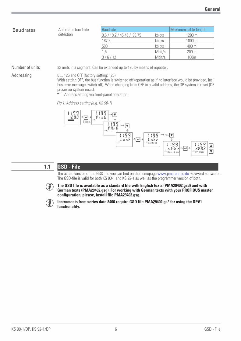
Baudrates Automatic baudratedetection
Baudrate Maximum cable length
9,6 / 19,2 / 45,45 / 93,75 kbit/s 1200 m187,5 kbit/s 1000 m500 kbit/s 400 m1,5 Mbit/s 200 m3 / 6 / 12 Mbit/s 100m
Number of units 32 units in a segment. Can be extended up to 126 by means of repeater.
Addressing 0 ... 126 and OFF (factory setting: 126)With setting OFF, the bus function is switched off (operation as if no interface would be provided, incl.bus error message switch-off). When changing from OFF to a valid address, the DP system is reset (DPprocessor system reset).w Address setting via front-panel operation:
1.1 GSD - FileThe actual version of the GSD-file you can find on the homepage www.pma-online.de keyword software..The GSD-file is valid for both KS 90-1 and KS 92-1 as well as the programmer version of both.
g The GSD file is available as a standard file with English texts (PMA29402.gsd) and withGerman texts (PMA29402.gsg). For working with German texts with your PROFIBUS masterconfiguration, please, install file PMA29402.gsg.
g Instruments from series date 8406 require GSD file PMA29402.gs* for using the DPV1functionality.
General
KS 90-1/DP, KS 92-1/DP 6 GSD - File
ProG1199
para
Ù3 Sek.
12001199
PArA1199
para
ConF1199
para
Ì
Ì
Cntr1199
para
Control
Ì
ÌÙ
Ìn *
othr1199
para
Auxiliar
Ù dP.Ad1199
para
DP-Addr
Fig 1: Address setting (e.g. KS 90-1)

1.2 Engineering SetFor easy comissioning there is an engineering set KS 90-1/DP (order-no.. 9407-999-10501). It can be usedwith KS 90-1 as well as with KS 92-1.
The Engineering set comprises:w Interface description for PROFIBUS-DP – Process Data
Document ”Interface description PROFIBUS-DP Process Data” (9499-040-66611) provides basicexplanations for connection of KS 90-1/DP to PROFIBUS-DP networks. It contains hints for cyclicalprocess data exchange.
w Interface description for PROFIBUS-DP Parameter DataDocument ”Interface description PROFIBUS-DP Parameter Data” (9499-040-65311) describesadditional functions for transfer of process values, parameters and configuration data via theparameter channel.
w Floppyconsisting of GSD file, example projects for SIEMENS STEP7 environments and HILSCHERCIF/SYCON applications, function blocks for parameter transmission with S7.
Pma29402.gsd GSD-file (English texts)
Pma29402.gsg GSD-file (German texts)
Pma_sup.arj Function module for STEP® 7 as library
KS90demo.zip Project example in STEP® 7 for S7-300
DevKS901.bctKS90cifV0.pbKS90cifV0.pb
Configuration example for BlueControl®
Configuration example forCIF�-interfaceConfiguration example forCIF�-interface
General
Engineering Set 7 KS 90-1/DP, KS 92-1/DP
3,5-Diskette (A:)
Ks901dp
Gsd
Example
S7_fb
Cif

2 Hints for operation
2.1 Connecting the interfaceThe PROFIBUS for KS 90-1 is connected to terminal connector B on the backside of the device, for KS 92-1to terminal connector E.The physical signals of the serial interface according to RS485 specification.
Cable construction must be done by the user. Thereby, the general cable specifications to IEC 61158 mustbe followed.
Sub-D bus adaptor
g It is recommended to use a standard PROFIBUS connectors(9-pole Sub-D) for an installation. For this purpose,connection to KS 90-1/DP is via a Sub-D bus adaptor whichmust be fitted. Order no.:
- 9407 998 07001 for flat pin connecting terminals- 9407 998 07011 for screw terminals.
Laying cables During cable laying, the general hints for cable laying made by the supplier of the master module must befollowed:w Cable run within buildings (inside and outside cabinets)w Cable run outside buildingsw Potential equalizationw Cable screeningw Measures against interference voltagesw Length of stub line
g For special hints for installation of PROFIBUS cables, see PNO Technical guideline“Installation guidelines for PROFIBUS-DP/FMS” (Order no. 2.111 [german]; 2.112 [engl.]).
Hints for operation
KS 90-1/DP, KS 92-1/DP 8 Connecting the interface
Fig.:2 PROFIBUS-DP connection
12131415
(16)17
B
Op
tio
n
P B A1
(2)
3
4
5
6
7
8
9
10
11
12
13
14
15
(16)
17
KS90-1
Op
tio
n
P B A1
(2)
3
4
5
6
7
8
9
10
11
12
13
14
15
(16)
17
KS90-1
Op
tio
n
P B A1
(2)
3
4
5
6
7
8
9
10
11
12
13
14
15
(16)
17
KS90-1
Fig.: 3 Wiring example with sub-D bus adaptor and bus connector
2.2 Hints for installationw Measurement and data lines should be kept separate from control and power supply cables.w Sensor measuring cables should be twisted and screened, with the screening connected to earth.w External contactors, relays, motors, etc. must be fitted with RC snubber circuits to manufacturer
specifications.w The unit must not be installed near strong electric and magnetic fields.
a The temperature resistance of connecting cables should be selected appropriately for thelocal conditions.
a The unit is not suitable for installation in explosion-hazarded areas.
a Faulty connection can lead to the destruction of the instrument.
a The device must be used only in environment with approved protection.
a The louvers of the device must not be covered.
a In plants where transient voltage peaks are susceptible to occur, the instruments must beequipped with additional protective filters or voltage limiters!
l Caution! The instrument contains electrostatically sensitive components.
a Please, follow the instructions given in the safety hints.
Hints for operation
Hints for installation 9 KS 90-1/DP, KS 92-1/DP

2.3 Remote/Local
Remote In status ‘REMOTE’ , all operations via the serial interface are possible (write and read). The followingoperations are still possible via the keys of the local operator interface:Display switch-over (extended operating level, error list), but no value changing.w Parameter viewing/reading, but no changing.w Configuration data viewing/reading, but no changing.w Switch-over via automatic/manual key
Local In the ‘LOCAL’ status, complete operation of the instrument via the keyboard is possible.
Switch-over Remote / local switch-over is possible via digital inputs, function key or all interfaces (BluePort®;PROFIBUS-DP). This switch-over is without effect on the interfaces.Write / read accesses via the interface (BluePort® or PROFIBUS) are always permitted..
Bus failure If the configuration data for front blocking is set to L_r = 0 (interface only) then in case of failure of thePROFIBUS, the switch-over from Remote to Local is automatic, i.e. local operation is possible.
2.4 PROFIBUS status displayFor PROFIBUS status display, two possibilities are provided:
w Messages in the error list
w Display via LED;configuration: LEd = 14 (bus error)
Display signification
Error list LED1) LED= on / error messageactive
Cause Remedial action
Dp.1 1No access by bus master wBus error
wConnector problemwNo bus connection
wCheck the cablewCheck the connectorwCheck the connections
Dp.2 2 Faulty configuration wFaulty DPconfiguration telegram
wCheck DP-configurationtelegram in the master
Dp.3 3Inadmissible parametersetting telegram was sent
wFaulty DP-parametersetting telegram
wCheck DP- parametersetting telegram in themaster
Dp.4 4No data communication wBus error
wAddress errorwMaster in stop
wCheck cable connectionwCheck addresswCheck master setting
1...4Internal error in DP-module(E.5)
wError during self-testw Internal communication
interrupted
w Switch on instrument againwContact PMA service
Hints for operation
KS 90-1/DP, KS 92-1/DP 10 Remote/Local
1) If configuration LED is configured to bus error.
3 Special functions
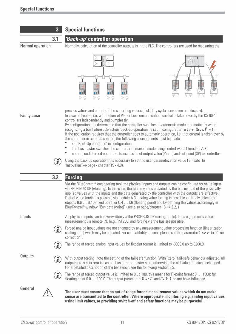
3.1 ‘Back-up’ controller operationNormal operation Normally, calculation of the controller outputs is in the PLC. The controllers are used for measuring the
process values and output of the correcting values (incl. duty cycle conversion and display).Faulty case In case of trouble, i.e. with failure of PLC or bus communication, control is taken over by the KS 90-1
controllers independently and bumplessly.By configuration it is determined that the controller switches to automatic mode automatically whenrecognizing a bus failure . Selection ‘back-up operation’ is set in configuration othr (BcuP = 1).If the application requires that the controller goes to automatic operation, i.e. that control is taken over bythe controller in automatic mode, the following arrangements must be made:w set ‘Back-Up operation’ in configurationw The bus master switches the controller to manual mode using control word 1 (module A.3).w normal, undisturbed operation: transmission of output value (Yman) and set-point (SP) to controller
g Using the back-up operation it is necessary to set the user parametrization value Fail-safe to‘last-value’(� page - chapter 19 - 4.3).
3.2 ForcingVia the BlueControl� engineering tool, the physical inputs and outputs can be configured for value inputvia PROFIBUS-DP (=forcing). In this case, the forced values provided by the bus instead of the physicallyapplied values with the inputs and the data generated by the controller with the outputs are effective.Digital value forcing is possible via module A.3, analog value forcing is possible via freely selectableobjects B.6 … B.10 (fixed point) or C.4 … C6 (floating point) and by defining the values accordingly inBlueControl� window ”Bus data (write)” (see also page/chapter 18 - 4.2.2. )
Inputs All physical inputs can be overwritten via the PROFIBUS-DP (configurable). Thus e.g. process valuemeasurement via remote I/O (e.g. RM 200) and forcing via the bus are possible.
g Forced analog input values are not changed by any measurement value processing function (linearization,scaling, etc.) which may be adjusted. For compatibility reasons please set the parameter Corr to “0: nocorrection”.
g The range of forced analog input values for fixpoint format is limited to -3000.0 up to 3200.0
Outputsg With output forcing, note the setting of the fail-safe function. With ”zero” fail-safe behaviour adjusted, all
outputs are set to zero in case of bus error or master stop, otherwise, the old value remains unchanged.For a detailed description of the behaviour, see the following section 3.3.
g The range of forced output value is limited to 0 up 100, this means for Fixpoint format 0 … 1000; forfloating point 0.0 … 100.0. The output parameters Out.0 and Out.1 do not have influence.
General
a The user must ensure that no out-of-range forced measurement values which do not makesense are transmitted to the controller. Where appropriate, monitoring e.g. analog input valuesusing limit values, or providing switch-off and safety functions may be purposeful.
Special functions
‘Back-up’ controller operation 11 KS 90-1/DP, KS 92-1/DP
1 2 3 4
°C°F
SP.2SP.E
parafuncAda
Err
12001199
run
02/12:30
1 2 3 4
°C°F
SP.2SP.E
parafuncAda
Err
12001199
run
02/12:30
1 2 3 4
°C°F
SP.2SP.E
parafuncAda
Err
12001199
run
02/12:30
1 2 3 4
°C°F
SP.2SP.E
parafuncAda
Err
12001199
run
02/12:30
F
KS 90-1 programmer
- PrgEdit -
/
F
KS 90-1 programmer
- PrgEdit -
/
F
KS 90-1 programmer
- PrgEdit -
/
F
KS 90-1 programmer
- PrgEdit -
/
1 2 3
°C°F
SP.2SP.E
parafuncAda
Err
12001199
run
02/12:30
F
KS 90 1
- PrgEdit -
/
1 2 3 4
°C°F
SP.2SP.E
parafuncAda
Err
12001199
run
02/12:30
F
KS
- PrgEdit -
/
1 2 3 4
°C°F
SP.2SP.E
rancdaErr
12001199
run
02/12:30
F
S 90-1 programmer
- PrgEdit -
/
K
1 2 3 4
CF
SP.2SP.E
12001199
run
02/12:30
F
90-1 programmer
- PrgEdit -
1 2 3 4
F
KS 90-1 programmer
- PrgEdit -
/
°C°F
SP.2SP.E
parafuncAda
Err
12001199
run
02/12:30
1 2 3 4
F
KS 90-1 programmer
- PrgEdit -
/
°C°F
SP.2SP.E
parafuncAda
Err
12001199
run
02/12:30
1 2 3 4
F
KS 90-1 programmer
- PrgEdit -
/
°C°F
SP.2SP.E
parafuncAda
Err
12001199
run
02/12:30
1 2 3 4
F
KS 90-1 programmer
- PrgEdit -
/
°C°F
SP.2SP.E
parafuncAda
Err
12001199
run
02/12:30
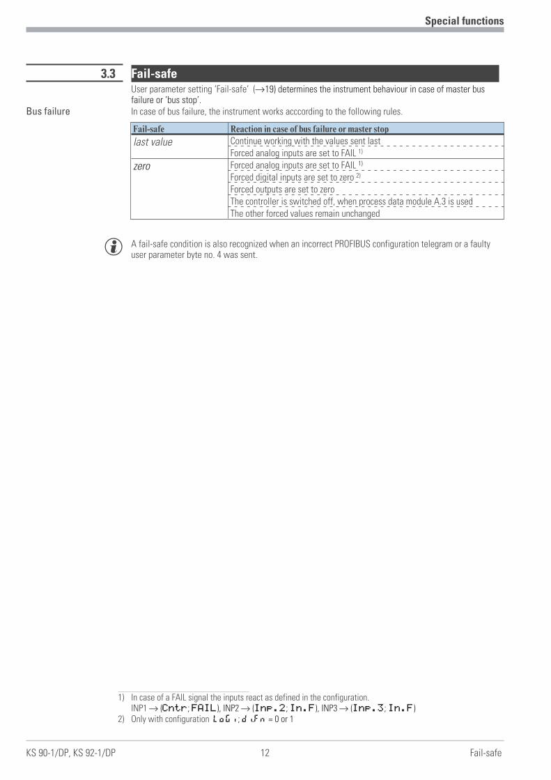
3.3 Fail-safeUser parameter setting ‘Fail-safe’ (r19) determines the instrument behaviour in case of master busfailure or ‘bus stop’.
Bus failure In case of bus failure, the instrument works acccording to the following rules.
Fail-safe Reaction in case of bus failure or master stop
last value Continue working with the values sent lastForced analog inputs are set to FAIL 1)
zero Forced analog inputs are set to FAIL 1)
Forced digital inputs are set to zero 2)
Forced outputs are set to zeroThe controller is switched off, when process data module A.3 is usedThe other forced values remain unchanged
g A fail-safe condition is also recognized when an incorrect PROFIBUS configuration telegram or a faultyuser parameter byte no. 4 was sent.
Special functions
KS 90-1/DP, KS 92-1/DP 12 Fail-safe
1) In case of a FAIL signal the inputs react as defined in the configuration.INP1r (Cntr; FAIL), INP2r (Inp.2; In.F), INP3r (Inp.3; In.F)
2) Only with configuration Logi; di.Fn = 0 or 1

4 Process data
4.1 IntroductionFor flexible realization of his requirements on transmitted values, memory space and transmission times,the user can compose the process data to be transmitted from a defined number of modules. Theconfiguration is effected by the particular bus master configuration tool.
Process data and selected parameter data are written and read cyclically.
g Forced values are taken over by the instrument only in case of value change.
Data format Values as e.g. process values and set-points can be transmitted in floating point format or as 16-bitFixPoint format with one digit behind the decimal point (selectable).
g During the FixPoint transmission the following limitations are to be considered:To data, which are defined as floating-point number in the equipment, applies:w Values are multiplied by the factor 10.
Example: 30.0 °C becomes 300.w The transferable range of values is -3000.0 to 3200.0. Pre-set values outside of the range are not
accepted.w If a range overflow occurs with a read value, then the value -3276.8 (as integer -32768) is transferred.w As switching off value the value -32000 has to be transferred in the FixPoint - format; during floating
decimal point transmission this is the value -32000.0.
For data, which are defined as integer value in the equipment, no transformation takes place.
Parameter channel Access to all process, parameter and configuration data is possible additionally via the parameterchannel. These data are transmitted on request over several cycles. These accesses are described indocumentation 9499 040 65311.
g The "universal module" offered by Siemens STEP7 in the hardware catalog is program determined andcannot be used.
Process data
Introduction 13 KS 90-1/DP, KS 92-1/DP
Fig.: 4 Example of hardware configuration for SIMATIC® S7
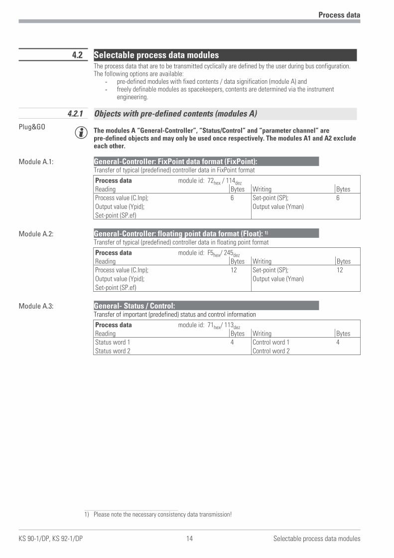
4.2 Selectable process data modulesThe process data that are to be transmitted cyclically are defined by the user during bus configuration.The following options are available:
- pre-defined modules with fixed contents / data signification (module A) and- freely definable modules as spacekeepers, contents are determined via the instrument
engineering.
4.2.1 Objects with pre-defined contents (modules A)
Plug&GOg The modules A “General-Controller”, “Status/Control” and “parameter channel” are
pre-defined objects and may only be used once respectively. The modules A1 and A2 excludeeach other.
Module A.1: General-Controller: FixPoint data format (FixPoint):Transfer of typical (predefined) controller data in FixPoint format
Process data module id: 72hex / 114dezReading Bytes Writing BytesProcess value (C.Inp);Output value (Ypid);Set-point (SP.ef)
6 Set-point (SP);Output value (Yman)
6
Module A.2: General-Controller: floating point data format (Float): 1)
Transfer of typical (predefined) controller data in floating point format
Process data module id: F5hex/ 245dezReading Bytes Writing BytesProcess value (C.Inp);Output value (Ypid);Set-point (SP.ef)
12 Set-point (SP);Output value (Yman)
12
Module A.3: General- Status / Control:Transfer of important (predefined) status and control information
Process data module id: 71hex/ 113dezReading Bytes Writing BytesStatus word 1Status word 2
4 Control word 1Control word 2
4
Process data
KS 90-1/DP, KS 92-1/DP 14 Selectable process data modules
1) Please note the necessary consistency data transmission!

Status word 1 Data contents of status word 1:
MSB LSBD15 D14 D13 D12 D11 D10 D9 D8 D7 D6 D5 D4 D3 D2 D1 D0
Bit no Name Allocation Status ‘0’ Status ‘1’D0 Auto/Man control signal manual/automatic Automatic Manual1)
D1 Coff control signal Coff not switched off Controllerswitched off
D2 y1 switching signal heating Off OnD3 y2 switching signal cooling Off OnD4 Lim1 limit 1 Off OnD5 Lim2 limit 2 Off OnD6 Lim3 limit 3 Off OnD7 L_r local /remote Local RemoteD8 di1 digital input 1 Off OnD9 di2 digital input 2 Off On
D10 di3 digital input 3 Off OnD11 SP/SP2 control signal SP.2 SP.2 not active SP.2 activeD12 SP/SP.E set-point internal / external internal externalD13 Y /Y2 switch-over to second output value Y Y2D14 Y / Y.E switch-over to external output value Y Y.ED15 Ada self tuning executed no yes
Status word 2 Data contents of status word 2:
MSB LSBD15 D14 D13 D12 D11 D10 D9 D8 D7 D6 D5 D4 D3 D2 D1 D0
Bit no. Name Allocation Status ‘0’ Status ‘1’D0 Fail sensor error of process value no yesD1 HCA heating current alarm no yesD2 SSR SSR alarm no yesD3 Loop loop alarm no yesD4 Fail 1 sensor error Inp.1 no yesD5 Fail 2 sensor error Inp.2 no yesD6 Fail 3 sensor error Inp.3 no yesD7 Error device fault no yesD8 NAK NAK (Error writing process data modules) no yesD9 Conf configuration mode no yes
D10 Para2 parameter set 1 / 2 Set 1 Set 2D11 Run programmer run Stop RunD12 Reset programmer reset ---- ResetD13 End program end ---- EndD14 UPD UPD (changed parameter/configuration data) no yesD15 DEX DEX (changed bus data assignment) no yes
Process data
Selectable process data modules 15 KS 90-1/DP, KS 92-1/DP
1) If the modules A1/A2 are used, the transferred output value Yman becomes effective with the change-over onhand.

Control word 1 Data contents of control word 1:
MSB LSBD15 D14 D13 D12 D11 D10 D9 D8 D7 D6 D5 D4 D3 D2 D1 D0
Bit no. Name Allocation Status ‘0’ Status ‘1’D0 Auto/Man automatic/manual Automatic Manual1)
D1 Coff controller on / off on offD2 - D6 always ‘0’
D7 L_r local / remote Local RemoteD8 di1 forcing di1 0 1D9 di2 forcing di2 0 1
D10 di3 forcing di3 0 1D11 SP/SP2 switch-over set-point SP/SP2 SP SP2D12 SP/SP.E switch-over set-point SP/SP.E SP SP.ED13 Y /Y2 switch-over output value Y/Y2 Y Y2D14 Y / Y.E switch-over output value Y/Y.E Y Y.ED15 Ada start self-tuning Stop Start
Control word 2 Data contents of control word 2:
MSB LSBD15 D14 D13 D12 D11 D10 D9 D8 D7 D6 D5 D4 D3 D2 D1 D0
Bit no. Name Allocation Status ‘0’ Status ‘1’D0 forcing Out.1 0 1D1 forcing Out.2 0 1D2 forcing Out.3 0 1D3 forcing Out.4 0 1D4 forcing Out.5 0 1D5 forcing Out.6 0 1
D6 - 9 always ‘0’D10 parameter set 1 /2 Set 1 Set 2D11 programmer run2) Stop RunD12 programmer reset ---- ResetD13 always ‘0’D14 clear UPD ---- ClearD15 clear DEX ---- Clear
UPD Parameter or configuration changing via the front panel during operation is signalled by the UPD bit instatus word 2.
DEX Changing the reference to a datum to be transmitted during operation via the engineering interfaceimplies a risk of value misinterpreting both by the bus master and KS90-1/DP. Such a change is signalledvia the DEX bit in status word 2. The master can evaluate the DEX bit and react accordingly.
Resetting UPD and DEX is possible via control word 2 or by switching the instrument off and on again.
Process data
KS 90-1/DP, KS 92-1/DP 16 Selectable process data modules
1) When using the module A.1 ord A.2 the output value set via bus will be effective immediately after a switch-overto manual mode.
2) The programmer state Reset becomes only valid in stop mode. To start the programmer the signal run mustchanged from 0 to 1.

Module A.4: General- Parameter channel:1)
Acyclical transfer possibilities for the complete device data
Parameter channel module id: F3hex/ 243dezReading Bytes Writing BytesReply data 8 Requested data 8
Detailed description see interface manual 9499 040 65311.
Module A.5: General- Activate write data:With this module the validity of write data can be controlled via the bus.
Release of write data in the cyclical process-data transferw 0 : Values are not accepted (Default)w 1 : Changed values are taken over from the busw 0�1 : Change from 0 to 1: all write data are taken over from the bus
Process data module id: 20hex / 32dezReading Bytes Writing Byte
0 Release 1
g If the module is not configured, all write data are accepted from the bus.
Process data
Selectable process data modules 17 KS 90-1/DP, KS 92-1/DP
1) Please note the necessary consistency data transmission!

4.2.2 Freely selectable transmission objects (modules B, C)
For modules B and C, the parameters to be transmitted and signals for reading and writing must beselected by means of the ‘BlueControl®’engineering tool. The positioning determines the order oftransmission (r Fig.: 5).
Modules B and C can be selected up to the limit of memory capacity or number of permitted modules.w max. input length of process data: 115 bytesw max. output length of process data: 115 bytesw max. number of modules: 57
Modules B: Variable input/output data: fixpoint format (FixP):
module words variable type module idB.1 1 IN1 FixP 50hex / 80dez
B.2 2 IN1 … IN2 FixP 51hex / 81dez
B.3 4 IN1 … IN4 FixP 53hex / 83dez
B.4 8 IN1 … IN8 FixP 57hex / 87dez
B.5 16 IN1 … IN16 FixP 5Fhex / 95dez
B.6 1 OUT1 FixP 60hex / 96dez
B.7 2 OUT1 … OUT2 FixP 61hex / 97dez
B.8 4 OUT1 … OUT4 FixP 63hex / 99dez
B.9 8 OUT1 … OUT8 FixP 67hex / 103dez
B.10 16 OUT1 … OUT16 FixP 6Fhex / 111dez
Modules C: Variable input/output data: floating point format (Float):1)
module words variable type module idC.1 2 IN1 float D1hex / 209dez
C.2 4 IN1 … IN2 float D3hex / 211dez
C.3 8 IN1 … IN4 float D7hex / 215dez
C.4 2 OUT1 float E1hex / 225dez
C.5 4 OUT1 … OUT2 float E3hex / 227dez
C.6 8 OUT1 … OUT4 float E7hex / 231dez
Process data
KS 90-1/DP, KS 92-1/DP 18 Selectable process data modules
Fig.: 5 Assignment of controller data for the fieldbus with ‘BlueControl®’
1) Please note the necessary consistency data transmission!

4.3 User parameter setting
4.3.1 Parameter setting for DPV0 - master
In addition to the standard parameter data, KS 90-1/DP has also user-specific parameter data.Adjustment is via the relevant bus master bus configuration tool.
User parameter setting is valid for the overall instrument. The signification of (4-byte) user parameterdata is shown in the following tables. These settings are not stored in the device; after power on thedefault settings are reactivated.
Bit Description. Signification1st..3rd
byteReserved for DP-V1These bytes are set to zero for DP-V0 operation.
Bit Description. Signification Default4th byte 0 Motorola / Intel
formatFormat for floating point values:Motorola (IEEE 754) / Intel (0 /1)For connection also to non-conforming PLCs or PCcardsexample: value 123.4 is inMotorola format : 42 F6 CC CDIntel format : CD CC F6 42
0 (Motorola)
1 Diagnosis format(rpg. 22 )
Diagnosis extended / standard (0 / 1)Extended diagnosis: standard diagnosis plusinstrument-specific diagnosis.Standard diagnosis: (6 bytes) withoutinstrument-specific infomation
0 (extended)
2 Fail-safe(rpg. 19)
Last value / zero (0 / 1)Behaviour with bus errors: holding existing valuesor zero setting, dependent of system concept .
0 (last value)
3..7 reserved 0
Process data
User parameter setting 19 KS 90-1/DP, KS 92-1/DP
Fig.: 6 User parameter setting as example of Step 7®

4.3.2 Parameter setting for DPV1 master
In addition to the instrument-specific DPV0 parameter setting data, further settings for DPV1 functionsare possible. These adjustments are also made via the relevant bus master bus configuration tool.With the instrumuent, the following functions can be selected and enabled:
- Operating mode according to DPV0 or DPV1- Reception of status alarms- Reception of manufacturer-specific alarms- Reception of diagnosis alarms- Reception of process alarms- Number of simultaneously active alarms (the instrument supports max. 32)
The user parameter setting is applicable throughout the instrument. The following tables explain thesignification of DPV1 specific settings (bytes 1 to 3). The instrument-specific parameters (byte 4) aredescribed in chapter 4.3.1, p. 19 . These settings are not stored in the device; after power on the defaultsettings are reactivated.
DPV1 status 1Bit Descr. Signification Default
1st byte 0..1 reserved2 WD_Base_1ms Instrument supports 1ms watchdog time base 1 (fixed)3..5 reserved6 Fail safe Instrument supports fail safe mode. During clear
mode, the instrument accepts data telegramswithout data.
1 (fixed)
7 DPV1 enable The class 1 master determines, if the instrumentmust work in DPV0 or DPV1 mode. The instrumentsupports the two versions.
defined bymaster
DPV1 status 2Bit Descr. Signification Default
2nd
byte0 Check_Cfg_Mode The instrument checks configuration data as
defined in IEC 611580
1 reserved2 Enable_Update_Alarm Not supported 03 Enable_Status_Alarm Transmission of status alarms is requested
optionallydefined bymaster
Process data
KS 90-1/DP, KS 92-1/DP 20 User parameter setting
Fig.: 7 User parameter setting at the example of Step® 7

Bit Descr. Signification Default4 Enable_Manufacture_Spe
cific_AlarmTransmission of manufacturer-specific alarmsis requested optionally
defined bymaster
5 Enable_Diagnostic_Alarm Transmission of diagnosis alarms is requestedoptionally
defined bymaster
6 Enable_Process_Alarm Transmission of process alarms is requestedoptionally
defined bymaster
7 Enable_Pull_Plug_Alarm Not supported 0
DPV1 status 3Bit Descr. Signification Default
3rd byte 0..2 Alarm_Mode Max. number of active alarms on the master Theinstrument supports 32 alarms.
defined bymaster
3..7 reserved
Process data
User parameter setting 21 KS 90-1/DP, KS 92-1/DP

4.4 PROFIBUS-DP diagnostic informationPROFIBUS-DP offers comfortable and versatile possibilities of processing diagnostic messages due toerror states. The diagnostic information of the instrument consists of standard diagnostic information (6bytes) and additional device specific diagnostic information. The latter can be switched off by userparametrization.
4.4.1 Standard - diagnostic message
A standard-diagnostic message consists of 6 bytes.
Bit Name Meaning1st byte 0 Diag.station Station does not exist (set by the master)
1 Diag.station_not_ready
Slave is not ready for data exchange
2 Diag.cfg_Fault Configuration data are not consistent3 Diag.ext_diag Slave has external diagnostic data1)
4 Diag.not_supported Requested service is not supported by the slave5 Diag.invalid_slave_res
ponseSlave sets fixed to 0
6 Diag.prm_fault Incorrect parameter setting (ID number etc.)7 Diag.master_lock (set
by master)Slave is parameterized by another master
Standarddiagnosis
Bit Name Meaning2nd
byte0 Diag.Prm_req Slave has to be parameterized again.
The application has identified a status, which requires a restartwith a new parameter setting and configuring. After the diagnosisthe master executes a start-up with given parameter setting andconfiguring.
1 Diag.Stat_diag Static diagnosisThe slave is not able to present valid data caused by a condition inthe application. The master requires thereupon only diagnosticinformation, until the slave takes this bit back again. ThePROFIBUS-DP status is however DATA Exchange, so that aftercanceling of the static diagnosis data exchange can be continuedimmediately again.
2 fixed on 13 Diag.WD_on Watchdog active4 Diag.freeze_mode Freeze command received5 Sync_Mode Sync command received6 reserved7 Diag.deactivated (set by the master)
Bit Name Meaning3rd byte 0..6 reserved
7 Diag.ext_overflow This bit is set by the slave, if more diagnostic data are available, asfit into the diagnostic data area.
Bit Name Meaning4th byte 0..7 Diag.master_add Master address after parameter setting (0xFF without parameter
setting)
Bit Name Meaning5th byte 0..7 ID number (high byte); 0x94
Bit Name Meaning6th byte 0..7 ID number (low-byte); 0x02
Process data
KS 90-1/DP, KS 92-1/DP 22 PROFIBUS-DP diagnostic information
1) When adjusting value “Diagnosis format” in user parameter setting byte 4 to “Standard diagnosis” this bitsignals that there is instrument-specific diagnosis information.

4.4.2 Device-specific diagnosis
The following device-specific diagnosis (during DPV1 mode: statusmessages) can be switched off via user parameter setting (rpg.22).Thus switching over to standard diagnosis is possible, e.g. for older DPmasters which do not support all functions, or when displayed diagnosisinformation is not of interest.
Bit Name Meaning7th byte 0..5 revision number revision number, e.g. 2
6, 7 always ‘1’
Bit Name Meaning8th byte 0..7 sign length 0x08: block length 8 bytes
Bit Name Meaning9th byte 0..7 status type 0x81: type Status Message
Bit Name Meaning10th byte 0..7 Slot number 0x00: slot: device
Bit Name Meaning11th byte 0..7 specifier 0x00: no status distinction
Bit Name Meaning12th byte 0..6 firmware version version of PROFIBUS software
Instrument-specificdiagnosis
Bit Name Meaning caused by13th byte 0 E.1 Internal error, cannot be removed e.g. defective EEPROM
1 E.2 Internal error, can be reset e.g. EMC problem2 E.3 Configuration error, can be reset e.g. faulty or missing configuration3 E.4 Hardware error Code number and hardware not identical4 E.5 Internal error in DP module5 InF.1 Operating hour limit message Preset number of operating hours reached6 InF.2 Switching cycle message (dig.
outputs)Preset number of switching cyclesreached
7 Reserved
Bit Name Meaning caused by14th byte 0 Lim.1 Limit value alarm 1 1) Adjusted limit value 1 exceeded
1 Lim.2 Limit value alarm 2 1) Adjusted limit value 2 exceeded2 Lim.3 Limit value alarm 3 1) Adjusted limit value 3 exceeded3 HCA Heating current alarm Heating circuit interruption, heater band destroyed4 SSR Heating current short circuit Current flow in heating circuit with controller off,
SSR defective, clotted5 Loop Control loop alarm Control loop is interrupted (input or output)6 /7 Reserved
Bit Name Meaning caused by15th byte 0 Fail.1 Sensor failure INP 1 Sensor defective, wiring fault
1 Fail.2 Sensor failure INP 2 Sensor defective, wiring fault2 Fail.3 Sensor failure INP 3 Sensor defective, wiring fault3..7 Reserved Please, note that earlier Simatic® S7 master versions do
not display the diagnosis values correctly.
g Please, note that earlier Simatic®
S7 master versions do not display the diagnosis values correctly.
Process data
PROFIBUS-DP diagnostic information 23 KS 90-1/DP, KS 92-1/DP
1) Only latched alarms are transmitted.The alarms can only be reset when acknowledging the alarm at the instrument.

4.4.3 Extended diagnosis for DPV1
In the DPV1 mode, the instrument supports an extended diagnosis function for alarm message signalling.The following marginal conditions are applicable:w The instrument is busy with data exchange.w The relevant alarm type was enabled in the user parameter setting.w The instrument supports the following alarm types:
- Diagnosis alarm- Process alarm- Status alarm (only for version programmer )- Manufacturer-specific alarm
Bit Descr. Signification16th byte 0..5 Header byte Length always ‘5dec’
6, 7 always ‘0’ ‘0’
Bit Descr. Signification17th byte 0..6 Alarm type 0x01: diagnosis alarm
0x02: process alarm0x05: status alarm0x20: (32dec) manufacturer-specific alarm
7 Alarm always ‘0’
Bit Descr. Signification18th byte 0..7 Slot number 0x00: Slot: instrument
alternativeDiagnosis alarm
Bit Descr. Signification19th byte 0..1 Alarm
specifier01: coming error10: going error, no error pending any more11: going error, other errors pending
2 Add Ack 0 : no further acknowledgement3..7 Seq no. Sequence number 0 … 31
Bit Descr. Signification Cause20th byte 0 Fail.1 INP1 sensor error Sensor defective, wiring error
1 Fail.2 INP2 sensor error Sensor defective, wiring error2 Fail.3 INP3 sensor error Sensor defective, wiring error3..7 Reserved
alternativeProcess alarm
Bit Descr. Signification19th byte 0..1 Alarm
specifier01: coming error10: going error, no error pending any more11: going error, other errors pending
2 Add Ack 1 : further acknowledgement required3..7 Seq no. Sequence number 0 … 31
Bit Descr. Signification Cause20th byte 0 Lim.1 Limit alarm 1 Adjusted limit value 1 exceeded
1 Lim.2 Limit alarm 2 Adjusted limit value 2 exceeded2 Lim.3 Limit alarm 3 Adjusted limit value 3 exceeded3 HCA Heating current alarm Heating circuit interruption, heater band
destroyed4 SSR Heating current short circuit Current flow in heating circuit with
controller off, SSR defective, conglutinated5 Loop Control loop alarm Control loop is interrupted (input or output)6 /7 Reserved
Process data
KS 90-1/DP, KS 92-1/DP 24 PROFIBUS-DP diagnostic information
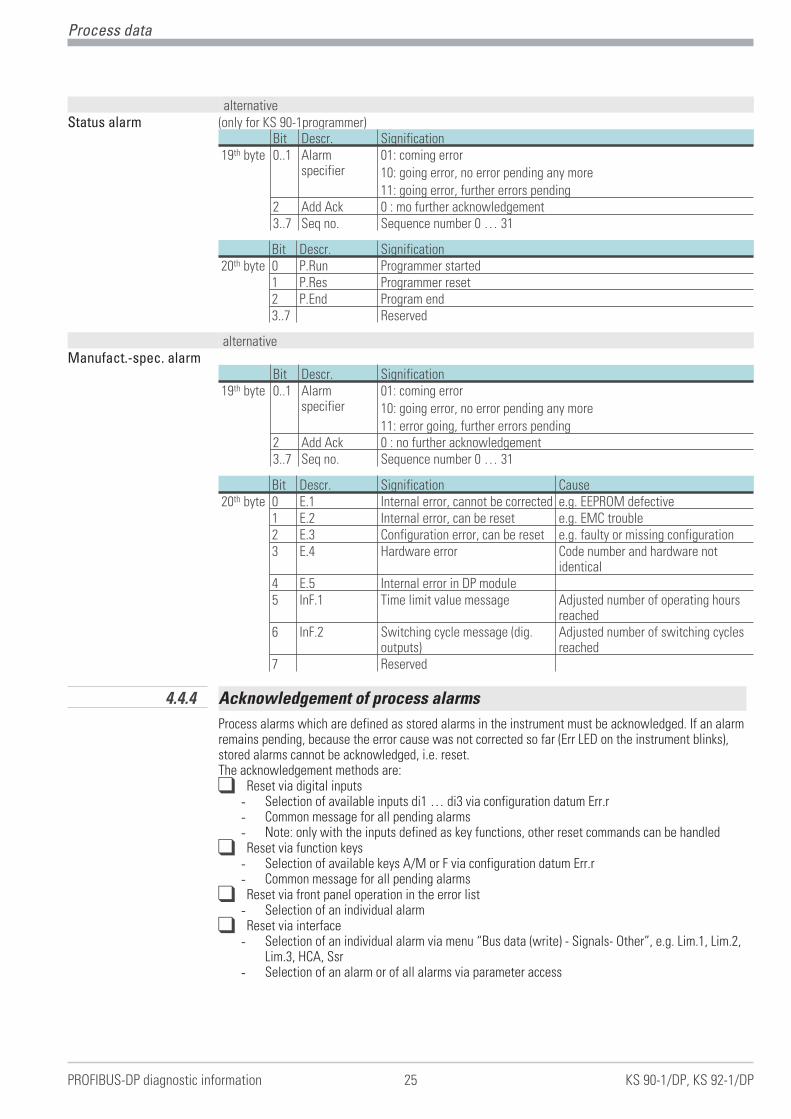
alternativeStatus alarm (only for KS 90-1programmer)
Bit Descr. Signification19th byte 0..1 Alarm
specifier01: coming error10: going error, no error pending any more11: going error, further errors pending
2 Add Ack 0 : mo further acknowledgement3..7 Seq no. Sequence number 0 … 31
Bit Descr. Signification20th byte 0 P.Run Programmer started
1 P.Res Programmer reset2 P.End Program end3..7 Reserved
alternativeManufact.-spec. alarm
Bit Descr. Signification19th byte 0..1 Alarm
specifier01: coming error10: going error, no error pending any more11: error going, further errors pending
2 Add Ack 0 : no further acknowledgement3..7 Seq no. Sequence number 0 … 31
Bit Descr. Signification Cause20th byte 0 E.1 Internal error, cannot be corrected e.g. EEPROM defective
1 E.2 Internal error, can be reset e.g. EMC trouble2 E.3 Configuration error, can be reset e.g. faulty or missing configuration3 E.4 Hardware error Code number and hardware not
identical4 E.5 Internal error in DP module5 InF.1 Time limit value message Adjusted number of operating hours
reached6 InF.2 Switching cycle message (dig.
outputs)Adjusted number of switching cyclesreached
7 Reserved
4.4.4 Acknowledgement of process alarms
Process alarms which are defined as stored alarms in the instrument must be acknowledged. If an alarmremains pending, because the error cause was not corrected so far (Err LED on the instrument blinks),stored alarms cannot be acknowledged, i.e. reset.The acknowledgement methods are:q Reset via digital inputs
- Selection of available inputs di1 … di3 via configuration datum Err.r- Common message for all pending alarms- Note: only with the inputs defined as key functions, other reset commands can be handled
q Reset via function keys- Selection of available keys A/M or F via configuration datum Err.r- Common message for all pending alarms
q Reset via front panel operation in the error list- Selection of an individual alarm
q Reset via interface- Selection of an individual alarm via menu “Bus data (write) - Signals- Other”, e.g. Lim.1, Lim.2,
Lim.3, HCA, Ssr- Selection of an alarm or of all alarms via parameter access
Process data
PROFIBUS-DP diagnostic information 25 KS 90-1/DP, KS 92-1/DP

5 Engineering via PROFIBUS
The instrument offers facilities for uploading a complete engineering into the instrument or for reading itinto the PC via PROFIBUS by means of BlueControl®. These functions enable central stations to be buildup, e.g. without having to transmit the data via a PLC.The Instrument from DP version 2 supports up to 2 acyclical communications to class 2 masters and onecommunication to the class 1 master.
For building up acyclical communication, the following steps are required:w Determine the Target Rotation Timew Set up the BlueControl® transmission.
5.1 BlueControl® via PROFIBUS-DPV1Data transmission between BlueControl® and the instrument is easy via the DPV1 functions. A completeengineering, operating functions and trend recording are possible and can be transmitted.
g From version 1.5, the BlueControl® engineering tool presently supports the PROFIBUS PC cards makeHilscher, e.g. CIF50-PB, CIF60-PB, firmware version � 1.0.71.
g From version 2.4, the BlueControl® engineering tool additionally supports the PROFIBUS PC cards madeby Siemens, e.g. CP5613.
For transmission, settings in the engineering tool and for the PROFIBUS card (Tool SyCon® ) are required.Following, the necessary settings in the engineering-tool and for the PROFIBUS-card are shown by exampleof a PC card by Fa. Hilscher.
Engineering via PROFIBUS
KS 90-1/DP, KS 92-1/DP 26
PROFIBUS
PLC operating
station
engineering-
station
DPV0 - cyclic DPV1 - acyclic DPV1 - acyclic
master class 1 master class 2master class 2
tokentoken
token
Fig.: 8 DPV1 connections
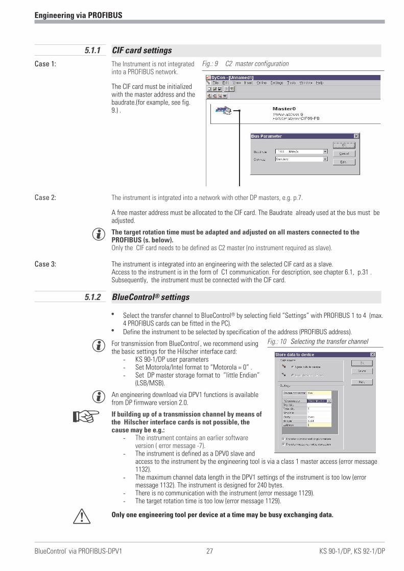
5.1.1 CIF card settings
Case 1: The Instrument is not integratedinto a PROFIBUS network.
The CIF card must be initializedwith the master address and thebaudrate.(for example, see fig.9.) .
Case 2: The instrument is intgrated into a network with other DP masters, e.g. p.7.
A free master address must be allocated to the CIF card. The Baudrate already used at the bus must beadjusted.
g The target rotation time must be adapted and adjusted on all masters connected to thePROFIBUS (s. below).Only the CIF card needs to be defined as C2 master (no instrument required as slave).
Case 3: The instrument is integrated into an engineering with the selected CIF card as a slave.Access to the instrument is in the form of C1 communication. For description, see chapter 6.1, p.31 .Subsequently, the instrument must be connected with the CIF card.
5.1.2 BlueControl® settings
w Select the transfer channel to BlueControl® by selecting field “Settings” with PROFIBUS 1 to 4 (max.4 PROFIBUS cards can be fitted in the PC).
w Define the instrument to be selected by specification of the address (PROFIBUS address).
g For transmission from BlueControl�
, we recommend usingthe basic settings for the Hilscher interface card:
- KS 90-1/DP user parameters- Set Motorola/Intel format to “Motorola = 0” .- Set DP master storage format to “little Endian”
(LSB/MSB).
g An engineering download via DPV1 functions is availablefrom DP firmware version 2.0.
+ If building up of a transmission channel by means ofthe Hilscher interface cards is not possible, thecause may be e.g.:
- The instrument contains an earlier softwareversion ( error message -7).
- The instrument is defined as a DPV0 slave andaccess to the instrument by the engineering tool is via a class 1 master access (error message1132).
- The maximum channel data length in the DPV1 settings of the instrument is too low (errormessage 1132). The instrument is designed for 240 bytes.
- There is no communication with the instrument (error message 1129).- The target rotation time is too low (error message 1129).
a Only one engineering tool per device at a time may be busy exchanging data.
Engineering via PROFIBUS
BlueControl®
via PROFIBUS-DPV1 27 KS 90-1/DP, KS 92-1/DP
Fig.: 9 C2 master configuration
Fig.: 10 Selecting the transfer channel

5.2 Hints for setting up the DP masterFor smooth operation, we recommend using the following DP master settings:w Enable the DPV1 functionality at the master and for the selected KS 90-1/DPw If applicable, specify the max. channel size (240 bytes)w Check or adjust the Token target rotation time.
g The Token target rotation time (Ttr) must not be too low, otherwise, the acyclic messagecannot be handled. This time defines the maximum available time for one Token rotation,within which all active DP masters get the permission for bus access once.
g When using one or several class 1 masters and one or several class 2 masters in amulti-master system, the token target rotation time must be set to the same value on allmasters, e.g. the sum of all individual times.
g At low PROFIBUS transfer-rates (9.6 bzw. 19.2 kBit/s) the preset target rotation time is to be enlarged atleast by factor 5.
a An incorrectly adjusted token target rotation time can cause communication troubles.
g The DPV1 transmission times are determined from Baudrate, overall number of data to be transmitted andsize of data to be transmitted in the addressed instrument. Example: typical values for transmission of adevice engineering are within 15 sec. and 3 min.
Further information on acyclic data transmission is given in interface description “SB PROFIBUS-DPparameter data” (9499-040-65311).
Engineering via PROFIBUS
KS 90-1/DP, KS 92-1/DP 28
master
class 1
master
class 2
slave 1 slave 2 slave 3
slave 1 slave 2 slave 3 slave 3
token
cycle
cyclic access master 1 acyclic access master 2
Fig.: 11 Token access

6 Getting started with SIMATIC®
S7
The disk enclosed in the engineering set contains the GSD file and project examples for a SIMATIC® S7.Communication with a process controller KS 90-1/ KS 92-1 can be built up easily by means ofconfiguration and project.
Test environmentThe following components are required for the exemplary test set-up:w Programming unit (PG) or PC with PC adaptorw Programming tool STEP®7 � V5.0w PLC
- e.g. CPU S7 315-2 DP, latest revision
Components w e.g. KS 90-1/DP, (e.g. order no. KS90-100-2000D-000)w Sub-D adaptor (e.g. order no. 9407-998-07001)w Engineering set (e.g. order no. 9407 999 10511)w Cable
- PROFIBUS cable PLC i KS90-1/DP with PROFIBUS connector and integrated terminationresistors
- PG i PLC
Test environment example:
Task w A KS 90-1/DP with address 5 shall be connected to CPU315-2 DP via PROFIBUS-DP.w Display or preadjustment of process value, set-point, input 2, deviation xw as well as of the low end
high limit of alarm 1 and of several status messages shall be possible.w A higher accuracy of input 2 and xw is required (float format).w For this, select process data modules A.1 (General Controller Format FixPoint), A.3 (General-Status /
Control), 2 modules C.1 for the float values, one 2-variable module B.2 for reading and one 2-variablemodule B.7 for writing of limit values.
g Before take the test environment into operation, you should ensure that the PLC do not contain any usersoftware (”clear/reset”).
Procedure:
w Make the connections (PROFIBUS)w Configure the instruments
- Load the example engineering from the floppy into KS 90-1/DP- Adjust address 5 to KS 90-1/DP (via front keys or BlueControl®)- connect instruments to PROFIBUS network- Activate the bus termination resistors.
Procedure w PROFIBUS-network configuration- Insert disk (Engineering Set) into PG.- Retrieve the example project (A:\KS901DP\S7_FB\EXAMPLE\KS90demo.zip)- Open project KS90-1demo.- if necessary adapt addresses and CPU hardware configuration and download it to the DP master
(CPU315-2 DP).- Switch PLC to run mode.
After commissioning of the test set-up testing the I/O area can be done by means of the variable tables(VAT 1) enclosed in the project.
Getting started with SIMATIC®
S7
021115 29 9499 040 66611

g Unless special extensions are required, the typical controller values can be exchanged via prefabricatedPlug&GO modules A.1/A.2 and A.3. For this purpose, no further settings on the KS 90-1/DP have to bedone except the address.
Getting started with SIMATIC®
S7
KS 90-1/DP, KS 92-1/DP 30 Hints for setting up the DP master
A.1 values
read from
controller
FixPoint
A.1 values
written to
controller
FixPoint
A.3
status words
control words
2x C.1
float words
B.2 - dual
integer value
B.7 - dual
integer value
Plug&GO
predefined
contents
contents
defined by
engineering
of KS 90-1/DP
Fig.: 13: VAT 1: Presentation of process data

6.1 Example - Hilscher interface card
6.1.1 Versions for DPV0
The floppy packed with the engineering set also contains project examples for a Hilscher interface card.Building up a DPV0 communication with a KS 90-1/DP process controller is easy by means of the systemconfigurator.
Test environmentThe following components are required for a test set-up example:w PC / notebookw System configurator SyCon�
w a CIF� interface card- e.g. CIF50-PB, CIF60-PB
Components w KS 90-1/DP, (e.g. order no. KS90-100-2000E-000)w Sub-D adaptor (e.g. order no. 9407-998-07001)w Engineering set (e.g. order no. 9407 999 10511)w Cable
- PROFIBUS cable PC i KS90-1/DP with PROFIBUS connectors and integrated terminatingresistors
Test environment example:
Task w A KS 90-1/DP with address 5 shall be connected to a CIF60-PB via PROFIBUS-DP.w Process value, set-point and some status messages shall be displayed or defined.w For this purpose, select process data modules A.1 (general controller format FixPoint), A.3 (general
status / control).Procedure:
w Build up communication (PROFIBUS).w Configure the instruments.
- Upload engineering example from floppy into KS 90-1/DP.- Adjust address 5 on KS 90-1/DP (via front panel or via BlueControl®) and connect to bus
network.- Activate bus terminating resistors.
Procedure w PROFIBUS network configuration- Insert floppy (engineering set) into the programming unit.- Open project example (e.g. A:\KS901DP\CIF\KS90cifV0.pb)- If necessary, adapt addresses and bus master hardware configuration and transmit them to the
DP master (menu Online\Download).- Start communication.
The following diagrams show the procedures and typical settings for this example:
Getting started with SIMATIC®
S7
Example - Hilscher interface card 31 KS 90-1/DP, KS 92-1/DP

w Network structure
w Selection of KS 90-1/DP process data modules
w DPV0 user parameter setting
Getting started with SIMATIC®
S7
KS 90-1/DP, KS 92-1/DP 32 Example - Hilscher interface card
Fig.: 14 Network configuration
Fig.: 15 Module selection
Fig.: 16 DPV0 user parameter setting

w Master settings
g For consistent data transmission, adjust transmission method ”buffered”. Set storage format "littleEndian" (LSB/MSB) for Motorola format.
w The data can be viewed in the network display
Getting started with SIMATIC®
S7
Example - Hilscher interface card 33 KS 90-1/DP, KS 92-1/DP
Fig.: 17 Master settings
Fig.: 18 Process data display

6.1.2 Versions for DPV1
In project example ..\CIF\KS90cifV1.pb packed with the engineering set, KS 90-1/DP is defined as DPV1slave. Possible settings are given in the following diagram.
Getting started with SIMATIC®
S7
KS 90-1/DP, KS 92-1/DP 34 Example - Hilscher interface card
Fig.: 19 DPV1 settings
7 Appendix
7.1 Installation hints
7.1.1 Minimum expansion of a PROFIBUS project
A PROFIBUS system consists at least of the following components:- a bus master controlling the data exchange,- a slave as participant or several, which makes data available on request of the master,- the transmitting medium, consisting of bus cable and bus plug for interconnecting the individual
users,- a bus segment or several, which are connected with repeater.
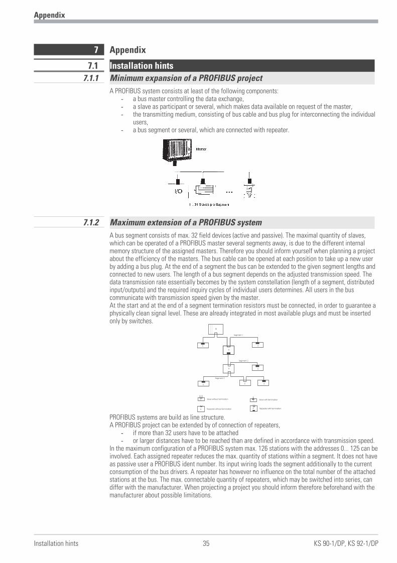
7.1.2 Maximum extension of a PROFIBUS system
A bus segment consists of max. 32 field devices (active and passive). The maximal quantity of slaves,which can be operated of a PROFIBUS master several segments away, is due to the different internalmemory structure of the assigned masters. Therefore you should inform yourself when planning a projectabout the efficiency of the masters. The bus cable can be opened at each position to take up a new userby adding a bus plug. At the end of a segment the bus can be extended to the given segment lengths andconnected to new users. The length of a bus segment depends on the adjusted transmission speed. Thedata transmission rate essentially becomes by the system constellation (length of a segment, distributedinput/outputs) and the required inquiry cycles of individual users determines. All users in the buscommunicate with transmission speed given by the master.At the start and at the end of a segment termination resistors must be connected, in order to guarantee aphysically clean signal level. These are already integrated in most available plugs and must be insertedonly by switches.
PROFIBUS systems are build as line structure.A PROFIBUS project can be extended by of connection of repeaters,
- if more than 32 users have to be attached- or larger distances have to be reached than are defined in accordance with transmission speed.
In the maximum configuration of a PROFIBUS system max. 126 stations with the addresses 0... 125 can beinvolved. Each assigned repeater reduces the max. quantity of stations within a segment. It does not haveas passive user a PROFIBUS ident number. Its input wiring loads the segment additionally to the currentconsumption of the bus drivers. A repeater has however no influence on the total number of the attachedstations at the bus. The max. connectable quantity of repeaters, which may be switched into series, candiffer with the manufacturer. When projecting a project you should inform therefore beforehand with themanufacturer about possible limitations.
Appendix
Installation hints 35 KS 90-1/DP, KS 92-1/DP
M
SS
S
SS
SS
R
R
RR
Slave without termination Slave with termination
Repeater without termination Repeater with termination
Segment 1
Segment 2
Segment 3
S

7.1.3 Wiring within buildings
The following installation notes apply to a twisted pair wires with screen. The screen serves theimprovement of the electromagnetic properties. A PROFIBUS cable according to line type A has a braidedscreen and a foil screen within the cable. The line screen in the following executions always containsboth screen versions (braided screen and foil screen). Always use both screens because the foil screenalone is very thin and can easily be interrupted, which leads to an interruption of the potential levelingsystem.
The line screen has to be connected at bothends with large surfaces to conducting materialto the reference earth. With the installation of arepeaters or a field device in a cubicle the linescreen should connected with cable clamps tothe ground busbar closely behind the cableentry.
The screen has to be continued up to the fielddevice and be connected there with theconducting case and/or the metallic plug. It is tocheck that the case of a device and the cubicle, in which the field device is installed have the same earthpotential. The assembly of a ground busbar on a painted surface is without effect. If these advises areapplied, high frequency interferences are conducted away through the braided screen. If interferencevoltages from the outside should break through to the data lines, the voltage potential on both data linesis raised in the same way, so that the differential voltage is not destructively influenced under normalconditions. With a shift of the earth potential of a few volts is still a safe data communication possible. Ifone expects a higher potential shift (potential DGND at the pin 5 against reference earth), then a potentialequalization line should be laid parallel to the bus with a minimum cross-sectional area of 10 mm², whichis to be connected with each field device at the reference earth of the field device. Most of the fielddevices have a central earth screw. In extreme disturbing environment the bus cable can be laid in a steeltube or a tight tin duct. The pipe or the duct is to be grounded then regularly.
The bus is to be installed always with a minimum distance of 20 cm to other lines, which carry a voltagehigher than 60 V. The bus cable is also to lay separated from telephone lines and cables, which lead intoexplosion protected areas. In such cases it is recommended to use a separate tin duct for the bus cable.
In a tin duct generally only conductive materials should be used, which are connected with the referenceearth regularly. The bus cables are not to be exposed to mechanical load or obvious damage. If suchimpact is expected, special preventive measures have to be taken e.g. installation in pipes etc.
Earth free installation:If the installation has to be earth-free for certain reasons, then the device mass is to be connected withthe reference earth only with a very high impedance (with a RC combination). The system searches itselfthen its own potential. With of connection of repeaters for interconnecting bus segments the earth-freeinstallation should generally be preferred, to avoid the transfer of potential differences from one bussegment into another.
Rail in cabinet nearthe cable entry gland
Functional ground Cable screening

7.2 Terms
BlueControl® Engineering tool software for BluePort® controller
BluePort®- interface interface at the front of the controller to connect an engineering tool
DPV0 Cyclic data exchange, basic functions
DPV1 acyclic services additional to DPV0
ET Abbreviation of engineering tool
Fail-safe behaviour of a device in case of PROFIBUS or bus master fault.
FB Abbreviation of function block
Float Abbreviation of floating point number
FixPoint data format with one fixed decimal point
Fkt Abbreviation for function
Forcing Presetting of input and output values via bus interface
Function a partial function of the function block which is self-contained seen from theinterface
Function block closed sequence unit
GSD file file of instrument data, standardarized description of communication capabilities
HW Abbreviation of hardware
Class 1 master Master handling the cyclical data exchange
Class 2 master Master for commissioning and engineering tasks
MS0 Cyclic communication between class 1 master and slave
MS1 acyclic communication between master class 1 and slave
MS2 acyclic communication between master class 2 and slave
Parameter channel Possibility to transfer data acyclically and sequentially within the cyclic processdata exchange
PG Abbreviation of programming unit
PNO PROFIBUS Nutzerorganisation
PROFIBUS-DP Standard communication protocol to IEC 61158 (DP: decentral peripheral units)
Real another term for floating point number
RS485 Standard 2-wire connection, half duplex, (EIA RS 485)
S5 / S7 PLC families of the Siemens AG
Serial interface rear bussable controller interface
SW Abbreviation of software
TTL Signal level at chip level
VAT Variable table: monitoring of values in STEP®7
Appendix
Terms 37 KS 90-1/DP, KS 92-1/DP

8 Index
Index
KS 90-1/DP, KS 92-1/DP 38 Terms
IndexAcknowlegdement of process-alarms . . . . . . . 25Addressing . . . . . . . . . . . . . . . . . . . . . . . . . . . . . 6Alarm
Diagnosis-alarm. . . . . . . . . . . . . . . . . . . . . 24Manufact.-spec. alarm. . . . . . . . . . . . . . . . 25Process-Alarm . . . . . . . . . . . . . . . . . . . . . . 24Status-Alarm . . . . . . . . . . . . . . . . . . . . . . . 25
Back-upFaulty case . . . . . . . . . . . . . . . . . . . . . . . . . 11
BlueControl® via PROFIBUS-DPV1 . . . . . 26 - 27bus failure . . . . . . . . . . . . . . . . . . . . . . . . . . . . 12Bus failure . . . . . . . . . . . . . . . . . . . . . . . . . . . . 10Bus fault . . . . . . . . . . . . . . . . . . . . . . . . . . . . . . 10Cable laying . . . . . . . . . . . . . . . . . . . . . . . . . . . . 8Cable specification. . . . . . . . . . . . . . . . . . . . . . . 8Control words. . . . . . . . . . . . . . . . . . . . . . . . . . 16
DEX. . . . . . . . . . . . . . . . . . . . . . . . . . . . . . . 16UPD . . . . . . . . . . . . . . . . . . . . . . . . . . . . . . 16
Data format . . . . . . . . . . . . . . . . . . . . . . . . . . . 13FixPoint. . . . . . . . . . . . . . . . . . . . . . . . . . . . 13Float . . . . . . . . . . . . . . . . . . . . . . . . . . . . . . 13
DiagnosisDevice specific . . . . . . . . . . . . . . . . . . . . . . 23Extension for DPV1 . . . . . . . . . . . . . . . . . . 24Standard. . . . . . . . . . . . . . . . . . . . . . . . . . . 22
Diagnosis and monitoring . . . . . . . . . . . . . . . . . 5Diagnostic information . . . . . . . . . . . . . . . 22 - 25Engineering via PROFIBUS . . . . . . . . . . . . 26 - 28Fail-safe . . . . . . . . . . . . . . . . . . . . . . . . . . . . . . 12
Last value . . . . . . . . . . . . . . . . . . . . . . . . . . 12Zero . . . . . . . . . . . . . . . . . . . . . . . . . . . . . . 12
Forcing . . . . . . . . . . . . . . . . . . . . . . . . . . . . . . . 11Getting started . . . . . . . . . . . . . . . . . . . . . 29 - 34Hints for installation . . . . . . . . . . . . . . . . . . . . . 9Hints for setting up the DP-Master. . . . . . . 28,30Line parameters . . . . . . . . . . . . . . . . . . . . . . . . . 5Module
A.1 . . . . . . . . . . . . . . . . . . . . . . . . . . . . . . . 14A.2 . . . . . . . . . . . . . . . . . . . . . . . . . . . . . . . 14A.3 . . . . . . . . . . . . . . . . . . . . . . . . . . . . . . . 14A.4 . . . . . . . . . . . . . . . . . . . . . . . . . . . . . . . 17A.5 . . . . . . . . . . . . . . . . . . . . . . . . . . . . . . . 17B . . . . . . . . . . . . . . . . . . . . . . . . . . . . . . . . . 18C . . . . . . . . . . . . . . . . . . . . . . . . . . . . . . . . . 18
Network topology. . . . . . . . . . . . . . . . . . . . . . . . 5Number of stations . . . . . . . . . . . . . . . . . . . . . . 6Objects freely selectable . . . . . . . . . . . . . . . . . 18Objects with pre-defined contents . . . . . . . . . 14Parameter channel . . . . . . . . . . . . . . . . . . . 13,17Plug&GO. . . . . . . . . . . . . . . . . . . . . . . . . . . . . . 14Process data . . . . . . . . . . . . . . . . . . . . . . . 13 - 25Status display. . . . . . . . . . . . . . . . . . . . . . . . . . 10Status words . . . . . . . . . . . . . . . . . . . . . . . . . . 15Sub-D adapter . . . . . . . . . . . . . . . . . . . . . . . . . . 8Terms . . . . . . . . . . . . . . . . . . . . . . . . . . . . 37 - 39Transmission media . . . . . . . . . . . . . . . . . . . . . . 5User parameter setting
DPV0-Master . . . . . . . . . . . . . . . . . . . 19 - 21DPV1-Master . . . . . . . . . . . . . . . . . . . . . . . 20
Wiring within buildings . . . . . . . . . . . . . . . . . . 36

Terms 39 KS 90-1/DP, KS 92-1/DP

Subject to alterations without notice. © PMA Prozeß- und Maschinen-Automation GmbHBei Änderungen erfolgt keine Mitteilung. Postfach 310 229, D - 34058 KasselModifications sans avertissement réservées. Printed in Germany 9499 040 66611 (02/2005)
A4,
unib
ind,
SW-D
ruck
Nor
mal
papi
erw
eiß
80g/
m2