Industrial Control - Bulletin 800G Hazardous Location Push ... · PDF fileBulletin 800G...
23
Bulletin 800G Hazardous Location Push Buttons Bulletin 800G — Hazardous Location Push Buttons Build a Catalog Number IP66, Type 4X Class I, Zone 1 and Zone 2 Class I/Division 2 — Groups A, B, C, and D Assembled Stations Bulletin 800G control stations are designed for Class I, Zone 1 and 2 and Class 1/Division 2 hazardous location applications. They consist of Bulletin 800G front-of-panel components with back-of-panel components: contact blocks or power modules. Bulletin 800G units are available as factory assembled stations or as components for component replacement. Field assembled stations used in a Class I, Zone 1 or Zone 2 application must be inspected and certified by a third party. Components Since the back-of-panel components are enclosed in a flame-proof enclosure, they are suitable for use in Class I, Zone 1 and Zone 2 Groups IIA, IIB, and IIC and Class I/Division 2, Groups A, B, C, and D hazardous locations and is listed by Underwriters Laboratories and certified by PTB for this class of service. The components have “d” and “e” protection methods except for the cable termination. Cable termination has only “d” protection method, restricted by the cable and not the contacts. CAUTION: The assembled stations and individual components listed herein are not suitable for the use in Zone 0, Class I/Division 1 and Class II/Division 1 and Division 2 applications. For Class I and II/Division 1 hazardous locations, order Bulletin 800H Type 7 & 9 stations and units. For Class II/ Division 2 hazardous locations, order Bulletin 800R stations. Standards Compliance UL 508 UL 1604 UL 60079-1, -7 CSA C22.2 No. 14 CSA C22.2 No. 213 CAN/CSA E60075-1, -7 EN/IEC 60947-5-1 EN/IEC 60079-1, -7 Certifications cULus Listed (File No. E10314, Guide No. NOIV, NOIV7, NWFN, NWFN7) ATEX Certified InMetro Build a Catalog Number Complete Assembled Stations
Transcript of Industrial Control - Bulletin 800G Hazardous Location Push ... · PDF fileBulletin 800G...

Bulletin 800G Hazardous Location Push Buttons
Bulletin 800G — Hazardous Location Push Buttons
Build a Catalog Number
IP66, Type 4X
Class I, Zone 1 and Zone 2
Class I/Division 2 — Groups A, B, C, and D
Assembled Stations
Bulletin 800G control stations are designed for Class I, Zone 1 and 2 and Class 1/Division 2 hazardous location applications.
They consist of Bulletin 800G front-of-panel components with back-of-panel components: contact blocks or power modules.
Bulletin 800G units are available as factory assembled stations or as components for component replacement. Field assembled
stations used in a Class I, Zone 1 or Zone 2 application must be inspected and certified by a third party.
Components
Since the back-of-panel components are enclosed in a flame-proof enclosure, they are suitable for use in Class I, Zone 1 and Zone 2 Groups IIA, IIB, and IIC and Class
I/Division 2, Groups A, B, C, and D hazardous locations and is listed by Underwriters Laboratories and certified by PTB for this class of service. The components
have “d” and “e” protection methods except for the cable termination. Cable termination has only “d” protection method, restricted by the cable and not the contacts.
CAUTION:The assembled stations and individual components listed herein are not suitable for the use in Zone 0, Class I/Division 1 and Class II/Division 1 and Division 2 applications. For Class Iand II/Division 1 hazardous locations, order Bulletin 800H Type 7 & 9 stations and units. For Class II/ Division 2 hazardous locations, order Bulletin 800R stations.
Standards Compliance
UL 508
UL 1604
UL 60079-1, -7
CSA C22.2 No. 14
CSA C22.2 No. 213
CAN/CSA E60075-1, -7
EN/IEC 60947-5-1
EN/IEC 60079-1, -7
Certifications
cULus Listed (File No. E10314, Guide No. NOIV, NOIV7, NWFN, NWFN7)
ATEX Certified
InMetro
Build a Catalog Number
Complete Assembled Stations
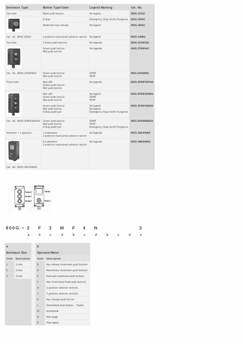
Enclosure Type Button Type/Color Legend Marking Cat. No.
One-hole Black push button No legend 800G-1F2A3
E-Stop Emergency Stop/Arrêt D'urgence 800G-1E4A3
Mushroom key release No legend 800G-1B4A3
Cat. No. 800G-1E4A3 2-position maintained selector switch No legend 800G-1HMA3
Two-hole 2 black push buttons No legends 800G-2F2AF2A3
Green push buttonRed push button
No legends 800G-2F3AF4A3
Cat. No. 800G-2FAAFBA3 Green push buttonRed push button
STARTSTOP
800G-2FAAFBA3
Three-hole Red LEDGreen push buttonRed push button
No legends 800G-3P4DF3AF4A3
Red LEDGreen push buttonRed push button
No legendSTARTSTOP
800G-3P4DFAAFBA3
Green push buttonRed push buttonE-Stop push/pull
No legendNo legendEmergency Stop/Arrêt D'urgence
800G-3F3AF4AE4A3
Cat. No. 800G-3P4DF3AF4A3 Green push buttonRed push buttonE-Stop push/pull
STARTSTOPEmergency Stop/Arrêt D'urgence
800G-3FAAFBAE4A3
Ammeter + 1 operator 1 A ammeter2-position maintained selector switch
No legends 800G-3M1XHMA3
5 A ammeter2-position maintained selector switch
No legends 800G-3M5XHMA3
Cat. No. 800G-3M1XHMA3
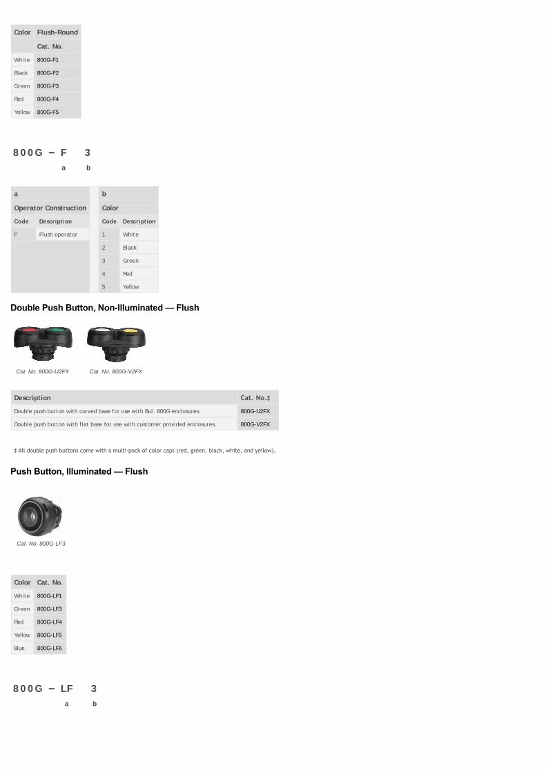
800G – 2 F 3 M F 4 N 3
a b c d b c d b c d e
a b
Enclosure Size Operator/Meter
Code Description Code Description
1 1-hole B Key release mushroom push button⋆
2 2-hole D Momentary mushroom push button‡
3 3-hole E Push‐pull mushroom push button⋆
F Non-illuminated flush push button#
H 2‐position selector switch‡
J 3‐position selector switch‡
K Key release push button
L Illuminated push button — flush∆
M Ammeter♣
N Hole plug‡
P Pilot light∆

c d
Push Button Color/Text Contact Block/Lamp Module
Code Description Code Description
1 White A 1 N.O. - 1 N.C. base mount
2 Black M 2 N.O. base mount
3 Green N 2 N.C. base mount
4 Red D Lamp module base mount (same color as requested lens color in Table c)
5 Yellow X N/A (i.e., ammeter, hole plug)
6 Blue K 1 N.O. with lamp module&
A START (green background/white text) L 1 N.C. with lamp module&
B STOP (red background/white text)
G I (green background/white text)
H O (red background/white text)
J ON (green background/white text)
K OFF (red background/white text)
Key Release
1 Lockable in initial position, key removal in initial position
2 Lockable in both positions, key removal in both positions
3 Lockable in depressed position, key removal in depressed position
Selector Switch
M Maintained in all positions
B Spring return from both positions♠
L Spring return from left♠
R Spring return from right♠
Meters
1 1 A
5 5 A
e e (cont'd) e (cont'd)
Conduit Entry Conduit Entry Conduit Entry
Bottom Entry Top Entry Through Feed▶
Code Description Code Description Code Description
Blank M20X1.5 threaded hole A M20X1.5 threaded hole M M20X1.5 threaded hole
1 1/2 in. NPT conduit hub B 1/2 in. NPT conduit hub N 1/2 in. NPT conduit hub
2 3/4 in. NPT conduit hub C 3/4 in. NPT conduit hub P 3/4 in. NPT conduit hub
3 1 M20 plastic cable gland for cable diameter 6…12 mm D 1 M20 plastic cable gland for cable diameter 6…12 mm Q 1 M20 plastic cable gland for cable diameter 6…12mm
4 1 M25 plastic cable gland for cable diameter 13…18mm
E 1 M25 plastic cable gland for cable diameter 13…18mm
R 1 M25 plastic cable gland for cable diameter 13…18mm
5 M20 blind plug F M20 blind plug T M20 blind plug
6 M25 blind plug G M25 blind plug U M25 blind plug
7 2 M20 plastic cable gland H 2 M20 plastic cable gland V 2 M20 plastic cable gland
8 1 M20 metal cable gland J 1 M20 metal cable gland W 1 M20 metal cable gland
9 1 M25 metal cable gland K 1 M25 metal cable gland X 1 M25 metal cable gland
0 2 M20 metal cable gland L 2 M20 metal cable gland Y 2 M20 metal cable gland
⋆ Only available in red.‡ Only available in black.♣ For ammeter, choose 3hole enclosure with meter in pos. 1 and either an operator or hole plug in pos. 2 (i.e., Cat. No. 800G3 M1X J1A or Cat. No. 800G3 M1X N2X) ∆ Only available in white, green, red, yellow, and blue.♠ Only available for 3position selector switch.▶ For throughfeed enclosure, selected conduit entry will be applied for both bottom and top entry.& For use with illuminated push button only.
# Only available in white, black, green, red, or yellow.
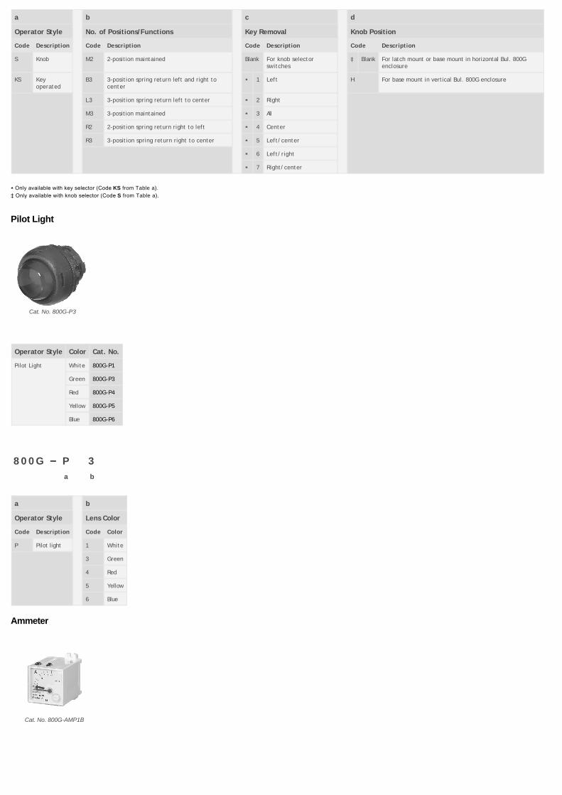
Push Button, NonIlluminated — Flush
Cat. No. 800G-F3
Color Flush-Round
Cat. No.
White 800G-F1
Black 800G-F2
Green 800G-F3
Red 800G-F4
Yellow 800G-F5
800G – F 3
a b
a b
Operator Construction Color
Code Description Code Description
F Flush operator 1 White
2 Black
3 Green
4 Red
5 Yellow
Double Push Button, NonIlluminated — Flush
Cat. No. 800G-U2FX Cat. No. 800G-V2FX
Description Cat. No.‡
Double push button with curved base for use with Bul. 800G enclosures. 800G-U2FX
Double push button with flat base for use with customer provided enclosures. 800G-V2FX
‡ All double push buttons come with a multi‐pack of color caps (red, green, black, white, and yellow).
Push Button, Illuminated — Flush
Cat. No. 800G-LF3
Color Cat. No.
White 800G-LF1
Green 800G-LF3
Red 800G-LF4
Yellow 800G-LF5
Blue 800G-LF6
800G – LF 3
a b

a b
Operator Construction Color
Code Description Code Description
LF Illuminated flush operator 1 White
3 Green
4 Red
5 Yellow
6 Blue
Mushroom — NonIlluminated and Key Release
Momentary Mushroom
Cat. No. 800G-M2
Key Release Mushroom
Cat. No. 800G-MKE
Push-Pull Mushroom
Cat. No. 800G-MPE
Color/Feature MomentaryMushroom
Key ReleaseMushroom
Push-Pull
Cat. No. Cat. No. Cat. No.
Black w/blackbezel
800G-M2 — —
E-Stop red w/yellow bezel ⋆
— 800G-MKE 800G-MPE
800G – M 2
a b
a b
Operator Style Color or Feature
Code Description Code Color
M Momentary 2 Black with black bezel
⋆ MP Push-pull E Red E-stop with yellow bezel and printing on head
⋆ MK Key release
⋆ Only available in Estop, option E from Table b.
Key Release
Cat. No. 800G-K14
Operator Style Locking Position Cat. No.
Key ReleasePush Button
Lockable in initial position, key removal in initial position 800G-K14
Lockable in both positions, key removal in both positions 800G-K16
Lockable in depressed position, key removal in depressed position 800G-K24
800G – K 14
a b

a b
Operator Style Locking Postion
Code Description Code Description
K Key release push button 14 Lockable in initial position; key removal in initial position
16 Lockable in both positions; key removal in both positions
24 Lockable in depressed position; key removal in depressed position
Selector Switch — Knob & Key Operated
Knob Selector Switch
Cat. No. 800G-SM3
Key Operated Switch
Cat. No. 800G-KSM33H
2-Postion Target Table
Contact Type
N.O. O X
N.C. X O
3-Position Target Table
Contact Type Pos. on Latch or Base
N.O. Top O O X
Bottom X O O
N.C. Top X X O
Bottom O X X
Operator Style Positions/Functions Knob Selector Switch
Cat. No.
2-Position Maintained 800G-SM2
3-Position S→M←S 800G-SB3
S→M M 800G-SL3
Maintained 800G-SM3
M M←S 800G-SR3
Operator Style Positions/Functions Key Removal Position Key Operated Switch
Cat. No.
2-Position Maintained All 800G-KSM23H
3-Position S→M←S Center 800G-KSB34H
S→M M Right/center 800G-KSL37H
Maintained All 800G-KSM33H
M M←S Left/center 800G-KSR35H
800G – S M3
a b c d
a b c d
Operator Style No. of Positions/Functions Key Removal Knob Position
Code Description Code Description Code Description Code Description
S Knob M2 2-position maintained Blank For knob selectorswitches
‡ Blank For latch mount or base mount in horizontal Bul. 800Genclosure
KS Keyoperated
B3 3-position spring return left and right tocenter
⋆ 1 Left H For base mount in vertical Bul. 800G enclosure
L3 3-position spring return left to center ⋆ 2 Right
M3 3-position maintained ⋆ 3 All
R2 2-position spring return right to left ⋆ 4 Center
R3 3-position spring return right to center ⋆ 5 Left/center
⋆ 6 Left/right
⋆ 7 Right/center
⋆ Only available with key selector (Code KS from Table a).
‡ Only available with knob selector (Code S from Table a).
Pilot Light
Cat. No. 800G-P3
Operator Style Color Cat. No.
Pilot Light White 800G-P1
Green 800G-P3
Red 800G-P4
Yellow 800G-P5
Blue 800G-P6
800G – P 3
a b
a b
Operator Style Lens Color
Code Description Code Color
P Pilot light 1 White
3 Green
4 Red
5 Yellow
6 Blue
Ammeter
Cat. No. 800G-AMP1B
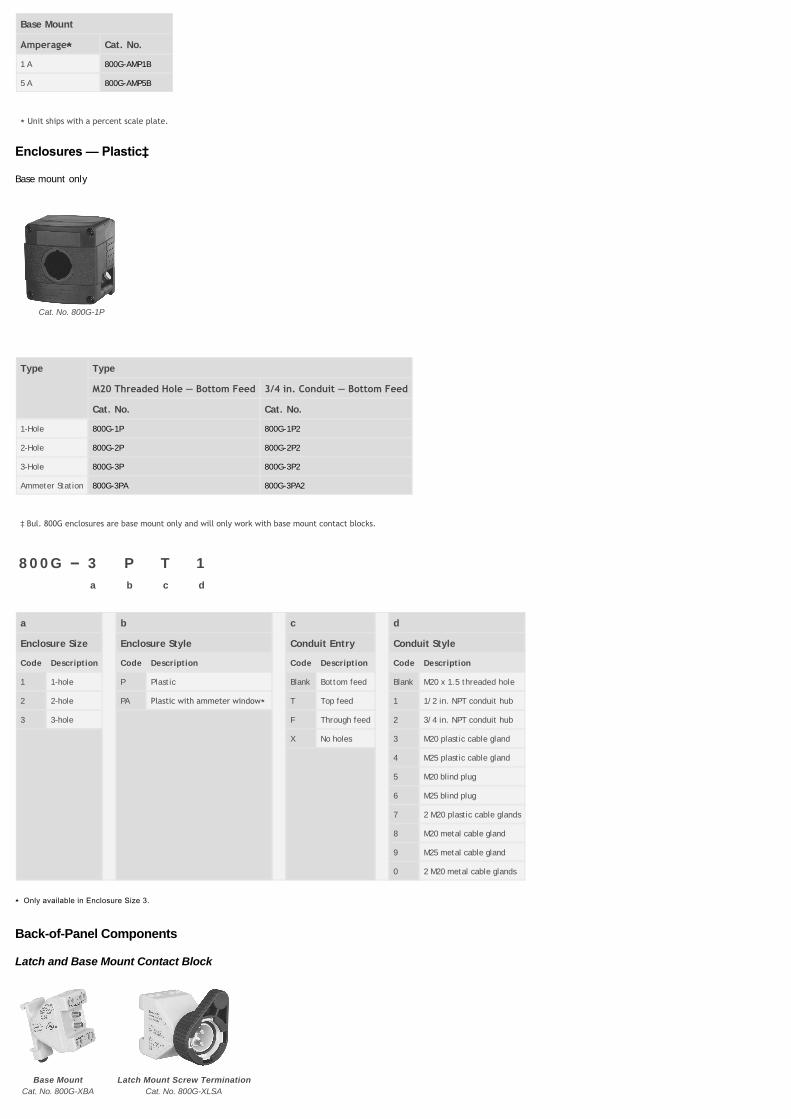
Base Mount
Amperage⋆ Cat. No.
1 A 800G-AMP1B
5 A 800G-AMP5B
⋆ Unit ships with a percent scale plate.
Enclosures — Plastic‡
Base mount only
Cat. No. 800G-1P
Type Type
M20 Threaded Hole — Bottom Feed 3/4 in. Conduit — Bottom Feed
Cat. No. Cat. No.
1-Hole 800G-1P 800G-1P2
2-Hole 800G-2P 800G-2P2
3-Hole 800G-3P 800G-3P2
Ammeter Station 800G-3PA 800G-3PA2
‡ Bul. 800G enclosures are base mount only and will only work with base mount contact blocks.
800G – 3 P T 1
a b c d
a b c d
Enclosure Size Enclosure Style Conduit Entry Conduit Style
Code Description Code Description Code Description Code Description
1 1-hole P Plastic Blank Bottom feed Blank M20 x 1.5 threaded hole
2 2-hole PA Plastic with ammeter window⋆ T Top feed 1 1/2 in. NPT conduit hub
3 3-hole F Through feed 2 3/4 in. NPT conduit hub
X No holes 3 M20 plastic cable gland
4 M25 plastic cable gland
5 M20 blind plug
6 M25 blind plug
7 2 M20 plastic cable glands
8 M20 metal cable gland
9 M25 metal cable gland
0 2 M20 metal cable glands
⋆ Only available in Enclosure Size 3.
Back-of-Panel Components
Latch and Base Mount Contact Block
Base Mount
Cat. No. 800G-XBA
Latch Mount Screw Termination
Cat. No. 800G-XLSA
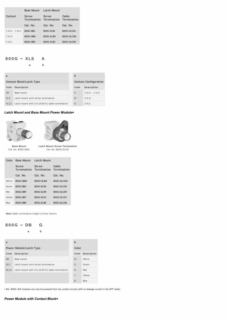
Base Mount Latch Mount
Contact ScrewTermination
ScrewTermination
CableTermination
Cat. No. Cat. No. Cat. No.
1 N.O. - 1 N.C. 800G-XBA 800G-XLSA 800G-XLC3A
2 N.O. 800G-XBM 800G-XLSM 800G-XLC3M
2 N.C. 800G-XBN 800G-XLSN 800G-XLC3N
800G – XLS A
a b
a b
Contact Block/Latch Type Contact Configuration
Code Description Code Description
XB Base mount A 1 N.O. - 1 N.C.
XLS Latch mount with screw termination M 2 N.O.
XLC3 Latch mount with 3 m (9.84 ft) cable termination N 2 N.C.
Latch Mount and Base Mount Power Module⋆
Base Mount
Cat. No. 800G-DBG
Latch Mount Screw Termination
Cat. No. 800G-DLSG
Color Base Mount Latch Mount
ScrewTermination
ScrewTermination
CableTermination
Cat. No. Cat. No. Cat. No.
White 800G-DBW 800G-DLSW 800G-DLC3W
Green 800G-DBG 800G-DLSG 800G-DLC3G
Red 800G-DBR 800G-DLSR 800G-DLC3R
Yellow 800G-DBY 800G-DLSY 800G-DLC3Y
Blue 800G-DBB 800G-DLSB 800G-DLC3B
Note:Cable termination length is three meters.
800G – DB G
a b
a b
Power Module/Latch Type Color
Code Description Code Description
DB Base mount W White
DLS Latch mount with screw termination G Green
DLC3 Latch mount with 3 m (9.84 ft) cable termination R Red
Y Yellow
B Blue
⋆ Bul. 800G LED modules can only be powered from dry contact circuits (with no leakage current in the OFF state).
Power Module with Contact Block⋆
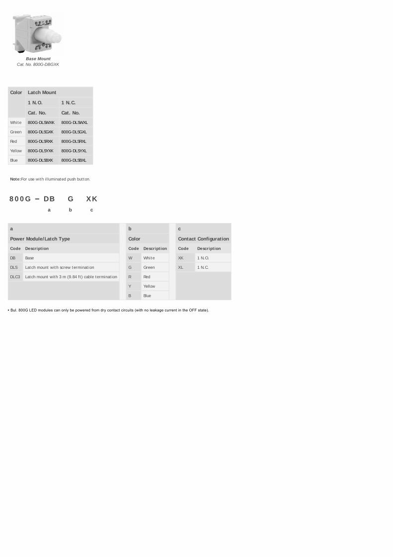
Base Mount
Cat. No. 800G-DBGXK
Color Latch Mount
1 N.O. 1 N.C.
Cat. No. Cat. No.
White 800G-DLSWXK 800G-DLSWXL
Green 800G-DLSGXK 800G-DLSGXL
Red 800G-DLSRXK 800G-DLSRXL
Yellow 800G-DLSYXK 800G-DLSYXL
Blue 800G-DLSBXK 800G-DLSBXL
Note:For use with illuminated push button.
800G – DB G XK
a b c
a b c
Power Module/Latch Type Color Contact Configuration
Code Description Code Description Code Description
DB Base W White XK 1 N.O.
DLS Latch mount with screw termination G Green XL 1 N.C.
DLC3 Latch mount with 3 m (9.84 ft) cable termination R Red
Y Yellow
B Blue
⋆ Bul. 800G LED modules can only be powered from dry contact circuits (with no leakage current in the OFF state).
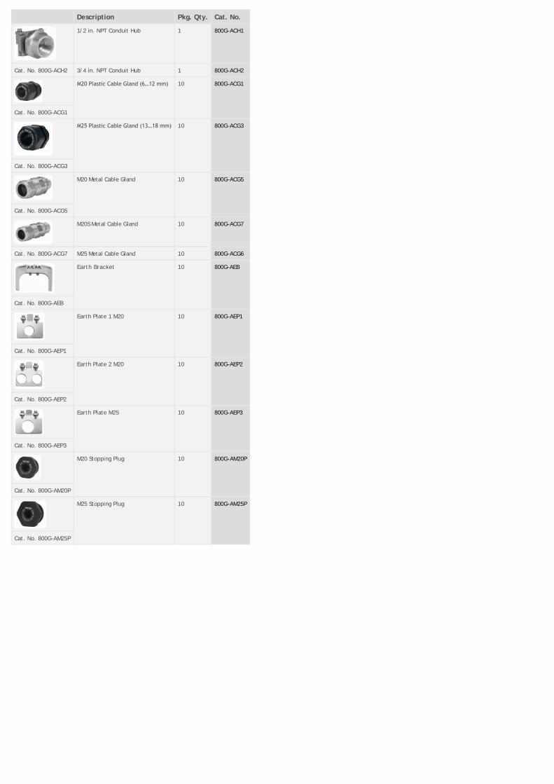
Description Pkg. Qty. Cat. No.
1/2 in. NPT Conduit Hub 1 800G-ACH1
Cat. No. 800G-ACH2 3/4 in. NPT Conduit Hub 1 800G-ACH2
M20 Plastic Cable Gland (6…12 mm) 10 800G-ACG1
Cat. No. 800G-ACG1
M25 Plastic Cable Gland (13…18 mm) 10 800G-ACG3
Cat. No. 800G-ACG3
M20 Metal Cable Gland 10 800G-ACG5
Cat. No. 800G-ACG5
M20S Metal Cable Gland 10 800G-ACG7
Cat. No. 800G-ACG7 M25 Metal Cable Gland 10 800G-ACG6
Earth Bracket 10 800G-AEB
Cat. No. 800G-AEB
Earth Plate 1 M20 10 800G-AEP1
Cat. No. 800G-AEP1
Earth Plate 2 M20 10 800G-AEP2
Cat. No. 800G-AEP2
Earth Plate M25 10 800G-AEP3
Cat. No. 800G-AEP3
M20 Stopping Plug 10 800G-AM20P
Cat. No. 800G-AM20P
M25 Stopping Plug 10 800G-AM25P
Cat. No. 800G-AM25P
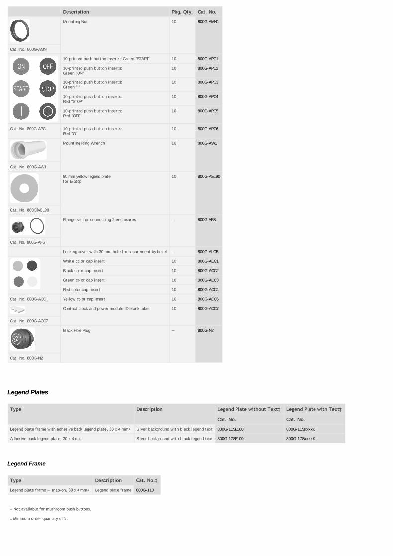
Description Pkg. Qty. Cat. No.
Mounting Nut 10 800G-AMN1
Cat. No. 800G-AMNI
10-printed push button inserts: Green "START" 10 800G-APC1
10-printed push button inserts:Green "ON"
10 800G-APC2
10-printed push button inserts:Green "I"
10 800G-APC3
10-printed push button inserts:Red "STOP"
10 800G-APC4
10-printed push button inserts:Red "OFF"
10 800G-APC5
Cat. No. 800G-APC_ 10-printed push button inserts:Red "O"
10 800G-APC6
Mounting Ring Wrench 10 800G-AW1
Cat. No. 800G-AW1
90 mm yellow legend platefor E-Stop
10 800G-AEL90
Cat. No. 800G AEL90
Flange set for connecting 2 enclosures — 800G-AFS
Cat. No. 800G-AFS
Locking cover with 30 mm hole for securement by bezel — 800G-ALCB
White color cap insert 10 800G-ACC1
Black color cap insert 10 800G-ACC2
Green color cap insert 10 800G-ACC3
Red color cap insert 10 800G-ACC4
Cat. No. 800G-ACC_ Yellow color cap insert 10 800G-ACC6
Contact block and power module ID blank label 10 800G-ACC7
Cat. No. 800G-ACC7
Black Hole Plug — 800G-N2
Cat. No. 800G-N2
Legend Plates
Type Description Legend Plate without Text‡ Legend Plate with Text‡
Cat. No. Cat. No.
Legend plate frame with adhesive back legend plate, 30 x 4 mm⋆ Silver background with black legend text 800G-11SE100 800G-11SxxxxK
Adhesive back legend plate, 30 x 4 mm Silver background with black legend text 800G-17SE100 800G-17SxxxxK
Legend Frame
Type Description Cat. No.‡
Legend plate frame — snap‐on, 30 x 4 mm⋆ Legend plate frame 800G-110
⋆ Not available for mushroom push buttons.
‡ Minimum order quantity of 5.

800G – 11 S E 166 K
a b c d e
a b c d e
Type Insert Color Language Legend Identification Type
Code Description Code Description Code Description Refer to Universal Code Description
11 Legend plate and frame S Silver background with black legend text E English K 0.080 size font
17 Legend plate only F French
G German
T Italian
S Spanish
U Universal symbol
Legend Frame
Cat. No. 800G-110
Adhesive Back Legend Plate
Cat. No. 800G-17SE100
Special Engraving
Besides the standard text and symbols listed on Universal, special legend plates are readily available.
To order:
• Select font code from table below.
• Specify desired text (please reference table below for restriction on characters and number of lines).
Type of Legend Size Font Size Font Code ApproximateSize
Max.Characters/Line
Max. Numberof Lines
Example Example (Legend Platewith Frame)
Legend Plate 30 x 4 mm Small K SAMPLE 19 1 800G-17SE100KSTARTER
800G-11SE100KSTARTER
Type Description Legend Plate without Text⋆ Legend Plate with Text⋆
Cat. No. Cat. No.
Enclosure identification label, 50 x 15 mm Silver background with black legend text 800G-AEL 800G-AEL_
⋆ Minimum order quantity of 5.
800G – AEL S LINE 1 , LINE 2 , LINE 3
a b c d e
a b c, d, e
Insert Color Font Size Customized Text
Code Description Code Description Example of customer specified text based on max. characters per line and max. number of lines. Whenseparated by a comma, the following text is to be engraved on the next line.
AEL Enclosure identification label with silverbackground and black text
S 0.10 sizefont
L 0.14 sizefont
Blank Enclosure Identification Label
Cat. No. 800G-AEL
Special Engraving
To order:

• Select desired font code table below (notes the max. characters and max. no. of lines).
• Specify desired text (please reference table below for restriction on characters and number of lines).
Type of Legend Size Font Size Font Code Approximate Size Max.Characters/Line
Max. Number ofLines
Example
Enclosure ID Label 50 x 15 mm Standard S SAMPLE 25 3 800G-AELS MACHINE 1,L-R27
Large L SAMPLE 19 2 800G-AELL MACH 1
Universal
Marking Suffix Number Marking Suffix Number
U226 I-O-II U234
U227 I-II-III U240
O U228 U241
I U229 U242
I I U230 I I I U249
I-O U232 U244
I-II U233 U245
0-1-2 U285 I-O-I U282
English

One-Word Marking
Marking Suffix Number Marking Suffix Number
AUTO E101 OFF E163
CLOSE E107 ON E166
DOWN E110 OPEN E170
EMERGENCY STOP
E112 OUT E173
FAULT E113 POWER ON E178
FAST E114 PUSH-TO-TEST E181
FORWARD E120 RAISE E182
HAND E126 RESET E186
HIGH E129 REVERSE E188
IN E132 RIGHT E191
INCH E134 RUN E193
JOG E138 SLOW E201
LEFT E145 START E208
LOW E148 STOP E212
LOWER E152 UP E223
Two-Word Marking
Marking Suffix Number Marking Suffix Number
FOR-REV E253 LEFT-RIGHT E146
HAND-AUTO E127 OFF-ON E165
HIGH-LOW E130 OPEN-CLOSE E171
INCH-REVERSE E135 RAISE-LOWER E183
JOG-FOR E255 SLOW-FAST E204
JOG-REV E256 START-STOP E211
JOG-RUN E142 UP-DOWN E224
Three-Word Marking
Marking Suffix Number Marking Suffix Number
FOR-STOP-REV E254 LOW-OFF-HIGH E150
FOR-OFF-REV E261 RAISE-OFF-LOWER E184
HAND-OFF-AUTO E128 SLOW-OFF-FAST E205
JOG-STOP-RUN E144 SLOW-OFF-START E207
HAND-O-AUTO E283
French
Marking Suffix Number Marking Suffix Number
Auto F101 Monter F182
Fermer F107 Arrière F188
Descendre F110 Droit F191
Panne F113 Régler F198
Rapide F114 Lent F201
Avant F120 Marche‐Arrêt F211
Avant‐Arrêt‐Arrière F122 Hors Circuit F244
Avant‐Arrière F124 En Circuit F245
Manuel F126 Hors F246
Manuel-Auto F127 En F247
Manuel‐Arrêt‐Auto F128 Hors-En F248
French, Continued

Marking Suffix Number Marking Suffix Number
Haut F129 Hors Manuel F249
Gauche F145 En Manuel F250
Bas F148 Arrêt‐Manuel F251
Bas‐Arrêt‐Haut F150 Demar. Man. F252
Arrêt F163 Av-Hors-Arr F253
Arrêt‐Marche F165 Surcharge F254
Marche F166 M Forcee F284
Ouvrir F170 — —
German
Marking Suffix Number Marking Suffix Number
Zu G107 Niedrig G148
Ab G110 Niedrig-Aus-Hoch G150
Störung G113 Senken G152
Schnell G114 Aus G163
Vor G120 Aus-Ein G165
Vor‐Aus‐Zurück G122 Ein G166
Vor‐Zurück G124 Heben G182
Hand G126 Zurück G188
Hand-Auto G127 Rechts G191
Hand-Aus-Auto G128 Langsam G201
Hoch G129 Auf G223
Links G145 Betrieb G243
Italian
Marking Suffix Number Marking Suffix Number
Automatico T101 Disinserito T163
Chiudere T107 Disins-Ins T165
Discesa T110 Inserito T166
Disturbo T113 Salita T182
Rapido T114 Indietro T188
Avanti T120 Destra T191
Avanti-Disins-Indietro T122 Preparare T198
Avanti-Indietro T124 Lento T201
Manuale T126 Marcia T208
Manuale-Auto T127 Marcia-Arresto T211
Manuale-Disins-Auto T128 Arresto T212
Alto T129 Aprire T223
Sinistra T145 In Servizio T243
Basso T148 Rotazione CW T246
Basso-Disins-Alto T150 Rotazione CCW T247
Abbassare T152 Emergenza T248
Spanish

Marking Suffix Number Marking Suffix Number
Cerrar S107 Abrir S170
Adelante S120 Subida S182
Adelante-Parada-Atrás
S123 Atrás S188
Adelante‐Atrás S124 Derecha S191
Manual S126 Marcha S208
Manual-Auto S127 Marcha-Parada S211
Izquierda S145 Parada S212
Bajada S152 En Servicio S243
Standard Assembled Stations
Mechanical Ratings
Protection Type II 2G Ex edm IIC T6AEx edm IIC T6Ex edm IIC T6
Certification PTB 01 ATEX 1036 UL E10314 CE0044
Rated Insulation Voltage Max. 690V AC
Rated current Dependent on components used
Degree of Protection IP66, Type 4X: ‐20…+60 °C (‐4…+140 °F)IP54: ‐55…+60 °C (‐67…+140 °F)
Enclosure Material
Enclosure Thermoplastic
Seals EPDM
Cable Glands
Standard Plastic M20 x 1.5 for cable Æ 6…12 mm
Custom Plastic M25 for cable Æ 13…18 mm1/2 in. NPT conduit3/4 in. NPT conduit
Wire/Cable Size 2.5 mm2 (12 AWG) stranded max.
PE Conductor Terminals 4 x 2.5 mm2 (12 AWG) stranded max.
Storage Temperature ‐55…+70 °C (‐67…+158 °F)
Operational Temperature Range ‐55…+60 °C (‐67…+140 °F)
Back-of-Panel
Contact Block
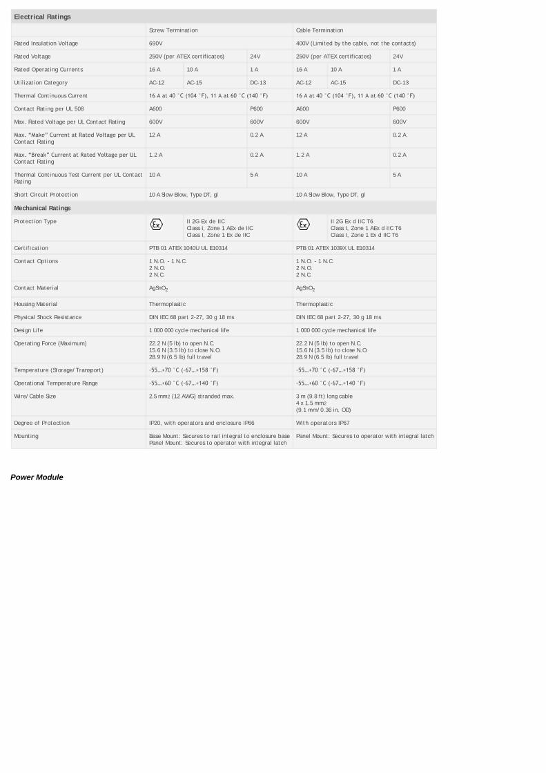
Electrical Ratings
Screw Termination Cable Termination
Rated Insulation Voltage 690V 400V (Limited by the cable, not the contacts)
Rated Voltage 250V (per ATEX certificates) 24V 250V (per ATEX certificates) 24V
Rated Operating Currents 16 A 10 A 1 A 16 A 10 A 1 A
Utilization Category AC-12 AC-15 DC-13 AC-12 AC-15 DC-13
Thermal Continuous Current 16 A at 40 °C (104 °F), 11 A at 60 °C (140 °F) 16 A at 40 °C (104 °F), 11 A at 60 °C (140 °F)
Contact Rating per UL 508 A600 P600 A600 P600
Max. Rated Voltage per UL Contact Rating 600V 600V 600V 600V
Max. “Make” Current at Rated Voltage per ULContact Rating
12 A 0.2 A 12 A 0.2 A
Max. “Break” Current at Rated Voltage per ULContact Rating
1.2 A 0.2 A 1.2 A 0.2 A
Thermal Continuous Test Current per UL ContactRating
10 A 5 A 10 A 5 A
Short Circuit Protection 10 A Slow Blow, Type DT, gl 10 A Slow Blow, Type DT, gl
Mechanical Ratings
Protection Type II 2G Ex de IICClass I, Zone 1 AEx de IICClass I, Zone 1 Ex de IIC
II 2G Ex d IIC T6Class I, Zone 1 AEx d IIC T6Class I, Zone 1 Ex d IIC T6
Certification PTB 01 ATEX 1040U UL E10314 PTB 01 ATEX 1039X UL E10314
Contact Options 1 N.O. - 1 N.C.2 N.O.2 N.C.
1 N.O. - 1 N.C.2 N.O.2 N.C.
Contact Material AgSnO2 AgSnO2
Housing Material Thermoplastic Thermoplastic
Physical Shock Resistance DIN IEC 68 part 2-27, 30 g 18 ms DIN IEC 68 part 2-27, 30 g 18 ms
Design Life 1 000 000 cycle mechanical life 1 000 000 cycle mechanical life
Operating Force (Maximum) 22.2 N (5 lb) to open N.C.15.6 N (3.5 lb) to close N.O.28.9 N (6.5 lb) full travel
22.2 N (5 lb) to open N.C.15.6 N (3.5 lb) to close N.O.28.9 N (6.5 lb) full travel
Temperature (Storage/Transport) ‐55…+70 °C (‐67…+158 °F) ‐55…+70 °C (‐67…+158 °F)
Operational Temperature Range ‐55…+60 °C (‐67…+140 °F) ‐55…+60 °C (‐67…+140 °F)
Wire/Cable Size 2.5 mm2 (12 AWG) stranded max. 3 m (9.8 ft) long cable4 x 1.5 mm2
(9.1 mm/0.36 in. OD)
Degree of Protection IP20, with operators and enclosure IP66 With operators IP67
Mounting Base Mount: Secures to rail integral to enclosure basePanel Mount: Secures to operator with integral latch
Panel Mount: Secures to operator with integral latch
Power Module
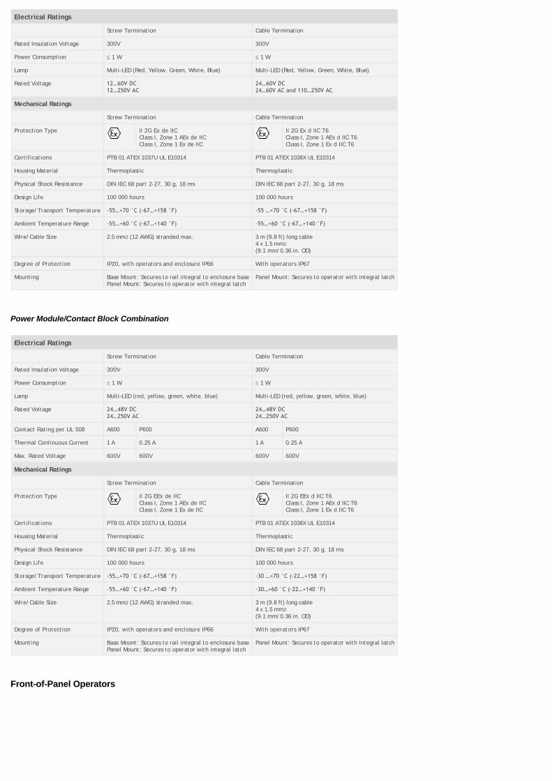
Electrical Ratings
Screw Termination Cable Termination
Rated Insulation Voltage 300V 300V
Power Consumption £ 1 W £ 1 W
Lamp Multi-LED (Red, Yellow, Green, White, Blue) Multi-LED (Red, Yellow, Green, White, Blue)
Rated Voltage 12…60V DC12…250V AC
24…60V DC24…60V AC and 110…250V AC
Mechanical Ratings
Screw Termination Cable Termination
Protection Type II 2G Ex de IICClass I, Zone 1 AEx de IICClass I, Zone 1 Ex de IIC
II 2G Ex d IIC T6Class I, Zone 1 AEx d IIC T6Class I, Zone 1 Ex d IIC T6
Certifications PTB 01 ATEX 1037U UL E10314 PTB 01 ATEX 1038X UL E10314
Housing Material Thermoplastic Thermoplastic
Physical Shock Resistance DIN IEC 68 part 2-27, 30 g, 18 ms DIN IEC 68 part 2-27, 30 g, 18 ms
Design Life 100 000 hours 100 000 hours
Storage/Transport Temperature ‐55…+70 °C (‐67…+158 °F) ‐55 …+70 °C (‐67…+158 °F)
Ambient Temperature Range ‐55…+60 °C (‐67…+140 °F) ‐55…+60 °C (‐67…+140 °F)
Wire/Cable Size 2.5 mm2 (12 AWG) stranded max. 3 m (9.8 ft) long cable4 x 1.5 mm2
(9.1 mm/0.36 in. OD)
Degree of Protection IP20, with operators and enclosure IP66 With operators IP67
Mounting Base Mount: Secures to rail integral to enclosure basePanel Mount: Secures to operator with integral latch
Panel Mount: Secures to operator with integral latch
Power Module/Contact Block Combination
Electrical Ratings
Screw Termination Cable Termination
Rated Insulation Voltage 300V 300V
Power Consumption £ 1 W £ 1 W
Lamp Multi-LED (red, yellow, green, white, blue) Multi-LED (red, yellow, green, white, blue)
Rated Voltage 24…48V DC24…250V AC
24…48V DC24…250V AC
Contact Rating per UL 508 A600 P600 A600 P600
Thermal Continuous Current 1 A 0.25 A 1 A 0.25 A
Max. Rated Voltage 600V 600V 600V 600V
Mechanical Ratings
Screw Termination Cable Termination
Protection Type II 2G EEx de IICClass I, Zone 1 AEx de IICClass I, Zone 1 Ex de IIC
II 2G EEx d IIC T6Class I, Zone 1 AEx d IIC T6Class I, Zone 1 Ex d IIC T6
Certifications PTB 01 ATEX 1037U UL E10314 PTB 01 ATEX 1038X UL E10314
Housing Material Thermoplastic Thermoplastic
Physical Shock Resistance DIN IEC 68 part 2-27, 30 g, 18 ms DIN IEC 68 part 2-27, 30 g, 18 ms
Design Life 100 000 hours 100 000 hours
Storage/Transport Temperature ‐55…+70 °C (‐67…+158 °F) ‐30 …+70 °C (‐22…+158 °F)
Ambient Temperature Range ‐55…+60 °C (‐67…+140 °F) ‐30…+60 °C (‐22…+140 °F)
Wire/Cable Size 2.5 mm2 (12 AWG) stranded max. 3 m (9.8 ft) long cable4 x 1.5 mm2
(9.1 mm/0.36 in. OD)
Degree of Protection IP20, with operators and enclosure IP66 With operators IP67
Mounting Base Mount: Secures to rail integral to enclosure basePanel Mount: Secures to operator with integral latch
Panel Mount: Secures to operator with integral latch
Front-of-Panel Operators

Mechanical Ratings
Device OperationalTemperature
Operating Force⋆
MechanicalDesign Life
ImpactResistance
Materials IngressProtection
Ex Protection Type
Push Button ‐55…+70 °C(‐67…+158 °F)
6.7 N(1.5 lb)
1 000 000 cycles 7 N•m ThermoplasticHousingEPDM Seals
IP66 :‐20…+70 °C(‐4…+158 °F)
IP54:‐55…‐20 °C(‐67…‐4 °F)
Type 4X:‐20…+70 °C(‐4…+158 °F)
II 2G EEx e IIPTB 01 ATEX 1035UUL E10314
Selector Switch ‐55…+70 °C(‐67…+158 °F)
—
Key ReleasePush Button
‐55…+70 °C(‐67…+158 °F)
15.6 N(3.5 lb)
Key ReleaseMushroom
‐55…+70 °C(‐67…+158 °F)
15.6 N(3.5 lb)
Mushroom ‐55…+70 °C(‐67…+158 °F)
6.7 N(1.5 lb)
E-Stop ‐55…+70 °C(‐67…+158 °F)
44.5 N Push/89 N Pull(10 lb Push/20 lb Pull)
6000 cycles
Pilot Light (Red,Yellow, White,Green, Blue)
‐55…+70 °C(‐67…+158 °F)
— N/A 4 N•m
Hole Plug ‐55…+70 °C(‐67…+158 °F)
— N/A 7 N•m
IlluminatedPush Button
‐55…+70 °C(‐67…+158 °F)
6.7 N(1.5 lb)
1 x 10⁶ 7 N•m
Key Selector Switch ‐55…+70 °C(‐67…+158 °F)
— 1 000 000 cycles 7 N•m
⋆ Does not include contact block.
Dimensions in millimeters (inches). Dimensions are not intended to be used for manufacturing purposes.

Push Buttons E-Stop
Mushroom Key Release Mushroom
Pilot Light Key Release
2-Position Selector Switch 3-Position Selector Switch
Dimensions are in millimeters (inches). Dimensions are not intended to be used for manufacturing purposes.
Contact Block

Cable Termination Screw Termination
Base Mount
Power Module
Cable Termination Screw Termination
Base Mount
Dimensions are in millimeters (inches). Dimensions are not intended to be used for manufacturing purposes.

Single Unit Double Unit
Triple Unit Measuring Instrument with Actuator
Vertical & Horizontal Spacing Mounting Dimension
Copyright © 2014 Rockwell Automation, Inc. All Rights Reserved.