Induction Motor
47
1 Introduction to Introduction to Electrical Machines Electrical Machines
-
Upload
gopal-prasanna -
Category
Documents
-
view
22 -
download
1
description
This file has the lecture notes of induction motor
Transcript of Induction Motor
1
Introduction to Electrical Introduction to Electrical MachinesMachines
2
ContentsContents
■ Basic construction and principles
■ DC machines
■ Synchronous machines
■ Induction machines

3
ObjectivesObjectives
■ When you have studied this chapter, you should:
■ have an understanding of electrical machines construction.
■ understand the principles of DC machines.
■ understand the principles and application of synchronous machines.
■ understand the principles and application of induction machines.
4
1. Basic Construction1. Basic Construction

5
IntroductionIntroduction
One of energy can be obtained from the other form with the help of converters. Converters that are used to continuously translate electrical input to mechanical output or vice versa are called electric machines.
The process of translation is known as electromechanical energy conversion.

6
Electric Machine
Electrical system
Mechanical system
Motor
GeneratorEnergy flow
e, i T, n
•An electrical machine is link between an electrical system and a mechanical system.
•Conversion from mechanical to electrical: generator
•Conversion from electrical to mechanical: motor

7
DC machine
Induction machine
Electrical Machines
Synchronous machine
•Machines are called AC machines (generators or motors) if the electrical system is AC.
•DC machines (generators or motors) if the electrical system is DC.
AC machine

8
Electrical system
Mechanical system
Coupling magnetic
fieldse, i T, n
Two electromagnetic phenomena in the electric machines:
•When a conductor moves in a magnetic field, voltage is induced in the conductor.
•When a current-carrying conductor is placed in a magnetic field, the conductor experiences a mechanical force.

9
•The structure of an electric machine has two major components, stator and rotor, separated by the air gap.
• Stator: Does not move and normally is the outer frame of the machine.
• Rotor:Is free to move and normally is the inner part of the machine. •Both rotor and stator are made of
ferromagnetic materials.
a'b
c'
ab'
c
Stator
Rotor
Electric Machines Electric Machines Basic StructureBasic Structure
Y’
BY
B’
Stator
Rotor
R
R’
N
S

10
DC Machines DC Machines ConstructionConstruction
11
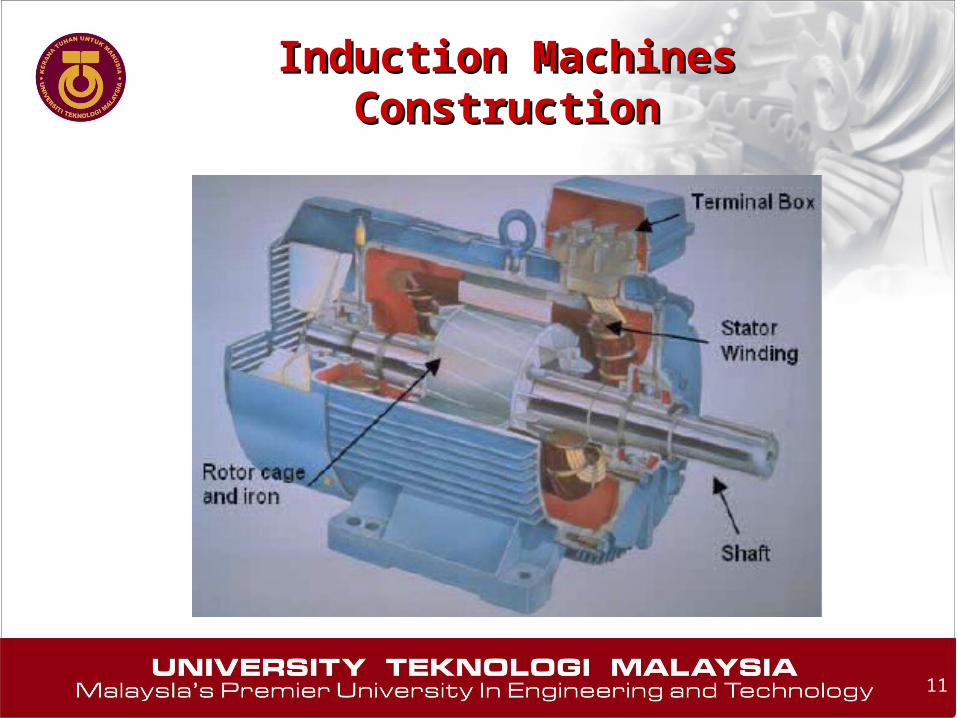
Induction Machines Induction Machines ConstructionConstruction

12
Synchronous Machines Synchronous Machines ConstructionConstruction

13
2. DC Machines2. DC Machines

14
3. Synchronous Machines3. Synchronous Machines
15
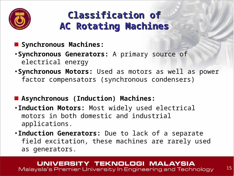
■ Synchronous Machines:
•Synchronous Generators: A primary source of electrical energy
•Synchronous Motors: Used as motors as well as power factor compensators (synchronous condensers)
■ Asynchronous (Induction) Machines:
•Induction Motors: Most widely used electrical motors in both domestic and industrial applications.
•Induction Generators: Due to lack of a separate field excitation, these machines are rarely used as generators.
Classification ofClassification ofAC Rotating MachinesAC Rotating Machines

16
■ Unlike induction machines, the rotating air gap field and the rotor rotate at the same speed, called the synchronous speed.
■ Synchronous machines are used primarily as generators of electrical power, called synchronous generators or alternators.
■ They are usually large machines generating electrical power at hydro, nuclear, or thermal power stations.
■ Application as a motor: pumps in generating stations, electric clocks, timers, and so forth where constant speed is desired.
Synchronous MachineSynchronous Machine

17
Synchronous MachinesSynchronous Machines
Generator
Exciter
View of a two-pole round rotor generator and exciter
18
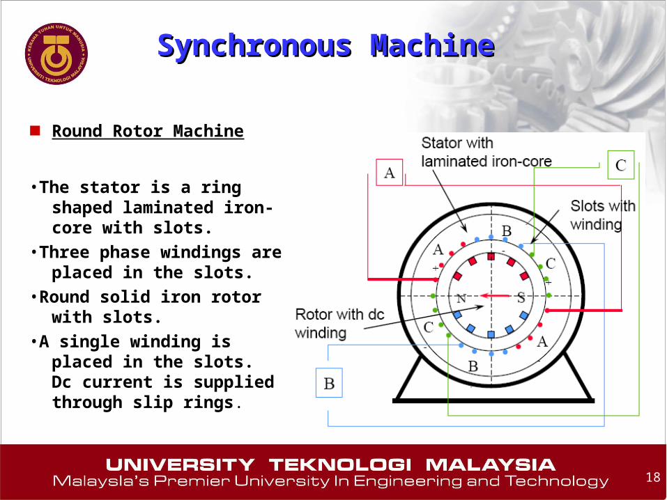
■ Round Rotor Machine
•The stator is a ring shaped laminated iron-core with slots.
•Three phase windings are placed in the slots.
•Round solid iron rotor with slots.
•A single winding is placed in the slots. Dc current is supplied through slip rings.
Synchronous MachineSynchronous Machine
19
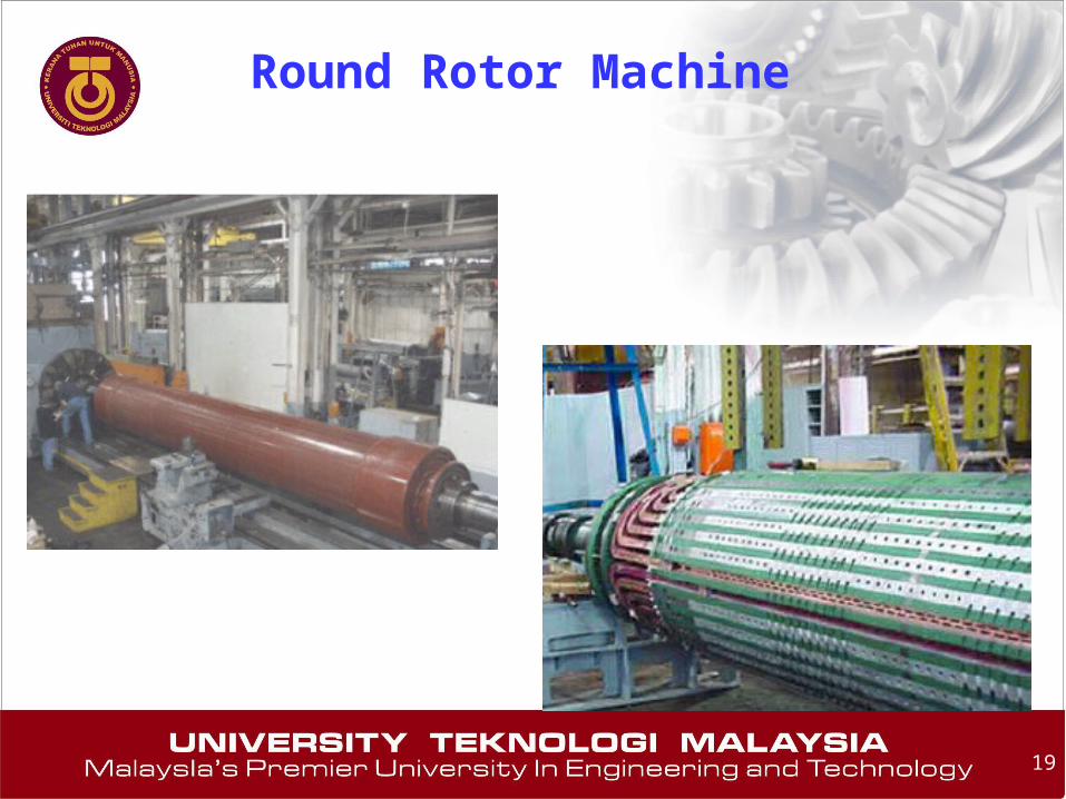
Round Rotor Machine
20
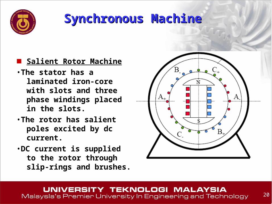
■ Salient Rotor Machine
•The stator has a laminated iron-core with slots and three phase windings placed in the slots.
•The rotor has salient poles excited by dc current.
•DC current is supplied to the rotor through slip-rings and brushes.
Synchronous MachineSynchronous Machine

21
Salient Rotor Machine

22
■ Principle of Operation
1) From an external source, the field winding is supplied with a DC current -> excitation.
2) Rotor (field) winding is mechanically turned (rotated) at synchronous speed.
3) The rotating magnetic field produced by the field current induces voltages in the outer stator (armature) winding. The frequency of these voltages is in synchronism with the rotor speed.
Synchronous GeneratorSynchronous Generator

23
■ Generators are rarely used in isolated situations. More commonly, generators are used in parallel, often massively in parallel, such as in the power grid. The following steps must be adhered to:
■ •when adding a generator to an existing power grid:
1) RMS line voltages of the two generators must be the same.
2) Phase sequence must be the same.
3) Phase angles of the corresponding phases must be the same.
4) Frequency must be the same.
Parallel Operation of Synchronous Parallel Operation of Synchronous GeneratorGenerator

24
4. Induction Machines4. Induction Machines

25
■ The induction machine is the most rugged and the most widely used machine in industry.
■ Both stator and rotor winding carry alternating currents.
■ The alternating current (ac) is supplied to the stator winding directly and to the rotor winding by induction – hence the name induction machine.
■ Application (1f): washing machines, refrigerators, blenders, juice mixers, stereo turntables, etc.
■ 2f induction motors are used primarily as servomotors in a control system.
■ Application 3f: pumps, fans, compressors, paper mills, textile mills, etc.
Induction MachineInduction Machine

26
Induction MotorsInduction Motors■ The single-phase
induction motor is the most frequently used motor in the world
■ Most appliances, such as washing machines and refrigerators, use a single-phase induction machine
■ Highly reliable and economical

27
Induction MotorsInduction Motors
■ For industrial applications, the three-phase induction motor is used to drive machines
■ Large three-phase induction motor. (Courtesy Siemens).
Housing
Motor
28
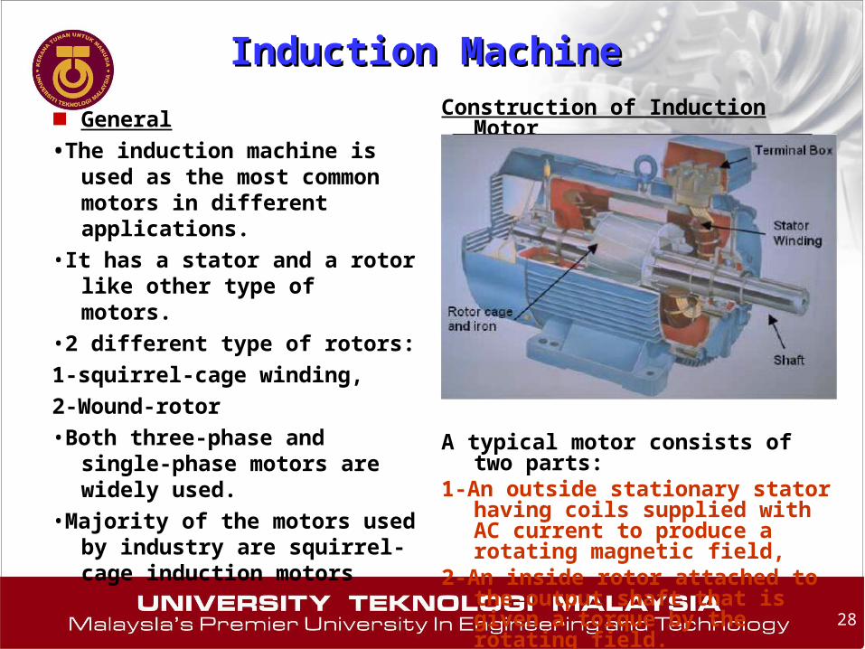
■ General
•The induction machine is used as the most common motors in different applications.
•It has a stator and a rotor like other type of motors.
•2 different type of rotors:
1-squirrel-cage winding,
2-Wound-rotor
•Both three-phase and single-phase motors are widely used.
•Majority of the motors used by industry are squirrel-cage induction motors
Construction of Induction Motor
A typical motor consists of two parts: 1-An outside stationary stator having
coils supplied with AC current to produce a rotating magnetic field,
2-An inside rotor attached to the output shaft that is given a torque by the rotating field.
Induction MachineInduction Machine

29
■ Basic principles:
■ •An AC current is applied in the stator armature which generates a flux in the stator magnetic circuit.
■ •This flux induces an emf in the conducting bars of rotor as they are “cut” by the flux while the magnet is being moved (E = BVL (Faraday’s Law))
■ •A current flows in the rotor circuit due to the induced emf, which in term produces a force, (F = BIL ) can be changed to the torque as the output.
Induction motor components.
Induction MotorInduction Motor

30
■ Stator construction
■ –The stator of an induction motor is laminated iron core with slots similar to a stator of a synchronous machine
■ –Coils are placed in the slots to form a three or single phase winding.
Single-phase stator with windings.
Induction MotorInduction Motor

31
Induction Motors Magnetic CircuitInduction Motors Magnetic Circuit
32
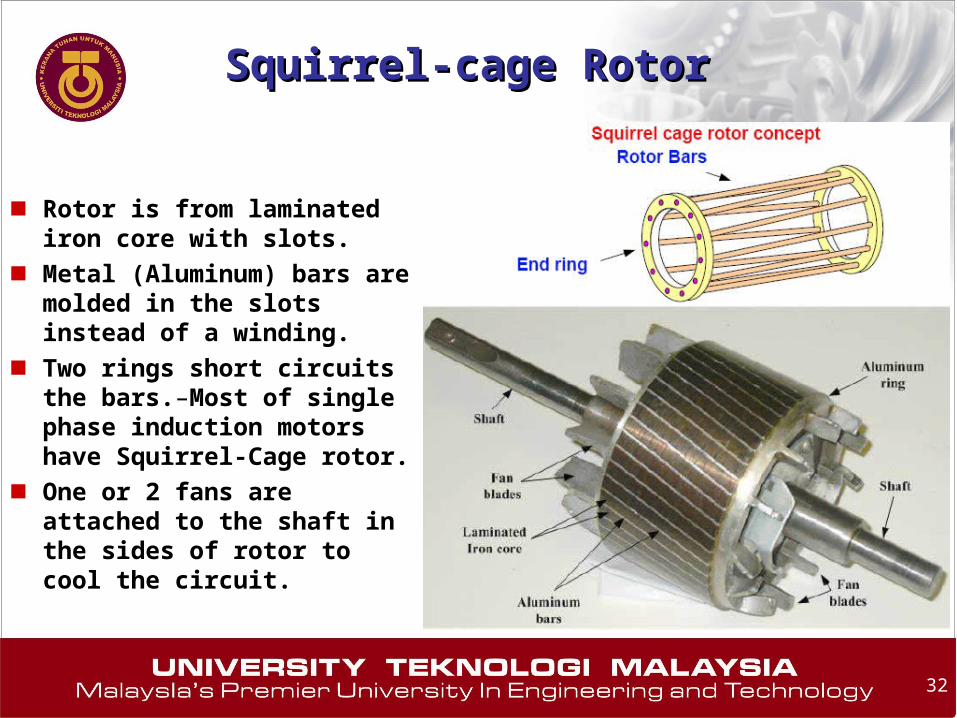
■ Rotor is from laminated iron core with slots.
■ Metal (Aluminum) bars are molded in the slots instead of a winding.
■ Two rings short circuits the bars.–Most of single phase induction motors have Squirrel-Cage rotor.
■ One or 2 fans are attached to the shaft in the sides of rotor to cool the circuit.
Squirrel-cage RotorSquirrel-cage Rotor

33
■ It is usually for large 3 phase induction motors.
■ •Rotor has a winding the same as stator and the end of each phase is connected to a slip ring.
■ •Three brushes contact the three slip-rings to three connected resistances (3-phase Y) for reduction of starting current and speed control.
Compared to squirrel cage rotors, wound rotor motors are expensive and require maintenance of the slip rings and brushes, so it is not so common in industry applications
•Wound rotor induction motor was the standard form for variable speed control before the advent of motor
Induction MotorInduction Motor
Rotor of a large induction motor.
(Courtesy Siemens).
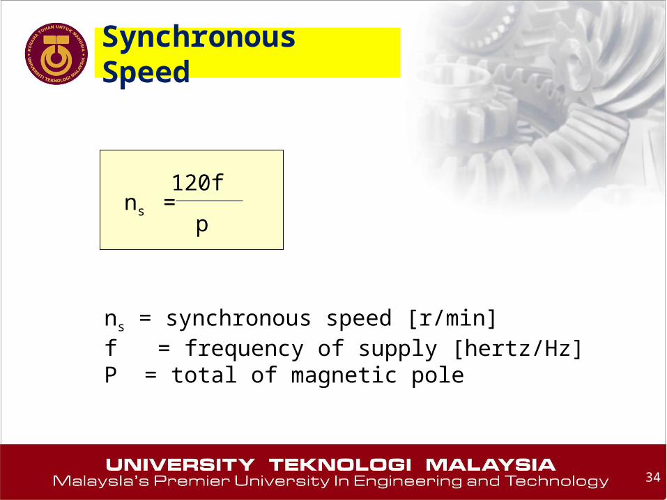
Synchronous Speed
34
ns =120f
p
ns = synchronous speed [r/min]f = frequency of supply [hertz/Hz]P = total of magnetic pole

35
Slip and Slip Speed Slip and Slip Speed
The slip s of an induction motor is the difference between the synchronous speed and the rotor speed, expressed as a Percent (per unit) of synchronous speed
The per-unit slip is given by the equation
S =ns - nr
ns
S = slipns = synchronous speed [r/min]nr = rotor speed [r/min]

36
Voltage and frequency induced in the rotor Voltage and frequency induced in the rotor
The voltage and frequency induced in the rotor both dependon the slip. They are given by the following equation
f2 = s f
E2 = s Eoc (approx.)
f2 = frequency of the voltage and current in the rotor [Hz]f = frequency of the source connected to the stator [Hz]s = slipE2 = voltage induced in the rotor at the slip sEoc = open-circuit voltae induced in the rotor when at rest [V]
37
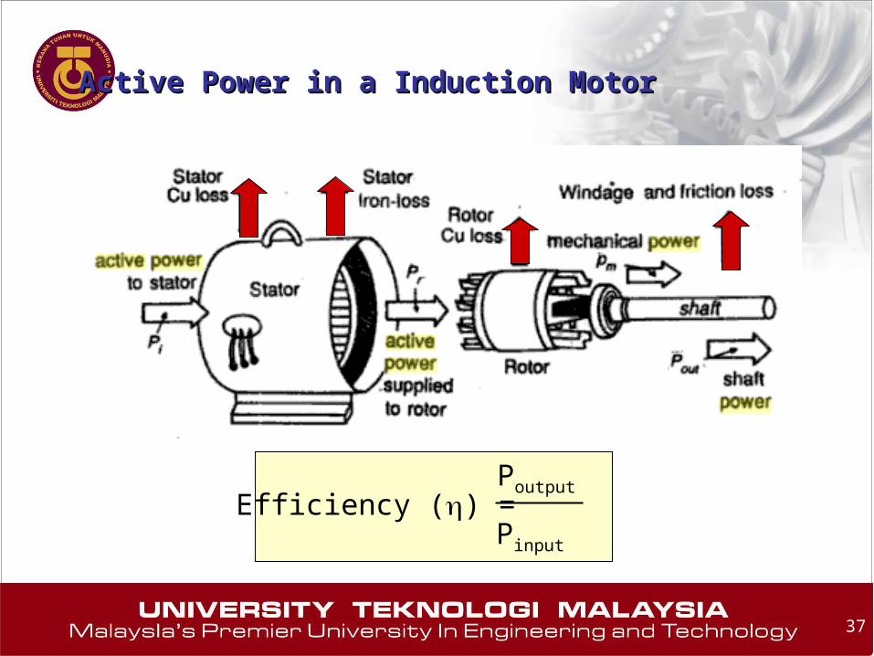
Active Power in a Induction MotorActive Power in a Induction Motor
Efficiency () =Poutput
Pinput

38
Motor Torque
Tm =9.55 Pm
n
9.55 (1 – s) Pr
ns (1 – s)=
= 9.55 Pr / ns
Tm = 9.55 Pr / ns
39
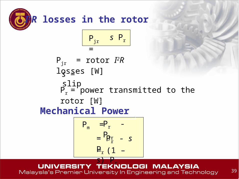
I2R losses in the rotor
Pjr = s Pr
Pjr = rotor I2R losses [W]
s = slip
Pr = power transmitted to the rotor [W]
Mechanical Power
Pm = Pr - Pjr
= Pr - s Pr
= (1 – s) Pr

40
Example 1Example 1
Calculate the synchronous speed of a 3-phase induction motor having 20 poles when it is connected to a 50 Hz source.

41
120 f
p
ns =
120 x 50
20=
300 r/min
Knowing quantities:Knowing quantities:
Source frequency = 50 Hz, number of poles = 20
Synchronous speed ns =
42
A 0.5 hp, 6-pole induction motor is excited by a 3-phase, 60 Hz source. If the full-load is 1140 r/min, calculate the slip.
Example 2Example 2
43
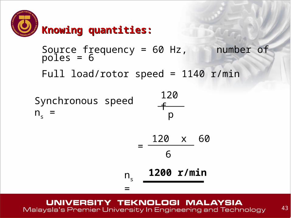
Knowing quantities:Knowing quantities:
Source frequency = 60 Hz, number of poles = 6
Full load/rotor speed = 1140 r/min
120 f
p
ns =
120 x 60
6=
1200 r/min
Synchronous speed ns =

44
Slip speed: ns – n = 1200 – 1140 = 60 r/min
Slip: s = (ns - n) / ns
= 60/1200
= 0.05 or 5%

45
Example 3Example 3

46
47
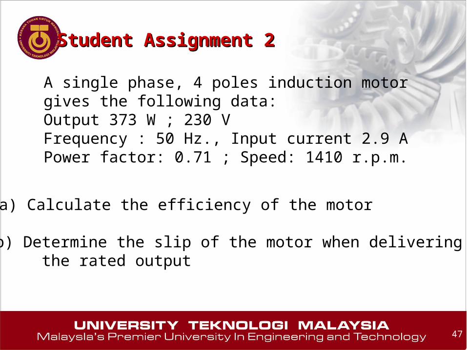
Student Assignment 2Student Assignment 2
A single phase, 4 poles induction motor gives the following data:Output 373 W ; 230 VFrequency : 50 Hz., Input current 2.9 APower factor: 0.71 ; Speed: 1410 r.p.m.
a) Calculate the efficiency of the motor
b) Determine the slip of the motor when delivering the rated output