INDOOR RADIO PROPAGATION KHAIRUL FAIZAL BIN ABDUL...
24
i INDOOR RADIO PROPAGATION KHAIRUL FAIZAL BIN ABDUL KADIR This report is submitted in partial fulfillment of the requirements for the award of Bachelor of Electronic Engineering (Computer Engineering) With Honours Faculty of Electronic and Computer Engineering Universiti Teknikal Malaysia Melaka April 2009
Transcript of INDOOR RADIO PROPAGATION KHAIRUL FAIZAL BIN ABDUL...

i
INDOOR RADIO PROPAGATION
KHAIRUL FAIZAL BIN ABDUL KADIR
This report is submitted in partial fulfillment of the requirements for the award of Bachelor of Electronic Engineering (Computer Engineering) With Honours
Faculty of Electronic and Computer Engineering
Universiti Teknikal Malaysia Melaka
April 2009

ii
UNIVERSITI TEKNIKAL MALAYSIA MELAKA
FAKULTI KEJURUTERAAN ELEKTRONIK DAN KEJURUTERAAN KOMPUTER
BORANG PENGESAHAN STATUS LAPORAN
PROJEK SARJANA MUDA II
Tajuk Projek : INDOOR RADIO PROPAGATION
Sesi Pengajian : 2008/2009
Saya KHAIRUL FAIZAL BIN ABDUL KADIR mengaku membenarkan Laporan Projek Sarjana Muda ini disimpan di Perpustakaan dengan syarat-syarat kegunaan seperti berikut:
1. Laporan adalah hakmilik Universiti Teknikal Malaysia Melaka.
2. Perpustakaan dibenarkan membuat salinan untuk tujuan pengajian sahaja.
3. Perpustakaan dibenarkan membuat salinan laporan ini sebagai bahan pertukaran antara institusi
pengajian tinggi.
4. Sila tandakan ( √ ) :
SULIT*
(Mengandungi maklumat yang berdarjah keselamatan atau kepentingan Malaysia seperti yang termaktub di dalam AKTA RAHSIA RASMI 1972)
TERHAD*
(Mengandungi maklumat terhad yang telah ditentukan oleh organisasi/badan di mana penyelidikan dijalankan)
TIDAK TERHAD
Disahkan oleh:
__________________________ ___________________________________
(TANDATANGAN PENULIS)
Alamat Tetap:
(COP DAN TANDATANGAN PENYELIA)
Tarikh: 30hb April 2009 Tarikh:
No. 1 Jalan Hujan Panas, 78300 Masjid Tanah, Melaka

iii
“I hereby declare that this report is the result of my own work except for quotes as cited in the references.”
Signature : ……………………………………………..
Author : KHAIRUL FAIZAL BIN ABDUL KADIR
Date : 30 APRIL 2009

iv
“I hereby declare that I have read this report and in my opinion this report is sufficient in terms of the scope and quality for the award of Bachelor Electronic
Engineering (Computer Engineering) With Honours.”
Signature :………………………….…
Supervisor’s Name :MR RIDUAN BIN AHMAD
Tarikh :…………….….……………

v
Dedicated to my beloved father and mother

vi
ACKNOWLEDGEMENTS
Firstly, Say prayer to the Allah S.W.T THE ALMIGHTY, the most merciful
and compassion for giving the writer this sole chance to jot down and elaborate some
meaningful information regarding to the activities that being done along the
completion of this thesis. A bouquet of gratitude to Mr. Riduan Bin Ahmad for his
limitless time and efforts in guiding and accessing my work.
A thousand of thank you to the writer’s working colleagues for their
invulnerable co-operations and supports along the completion of this training. The
writer also wants to wish thank you for those who support the writer directly or
indirectly towards the finishing episode of this training.
A great deal of appreciation also goes to the contribution of my faculty –
Faculty of Electronic and Computer Engineering (FKEKK).
Last but not least, the writer wants to wish thank you to his parents for their
morale support and influences along the completion of this Final Project Report.
THANK YOU

vii
ABSTRACT
Typically a wireless Mesh infrastructure is designed and installed by
networking Professionals. Indoor radio communication systems gain increasing
interest of cellular network operators. A prerequisite to the design of these systems is
the knowledge of indoor radio propagation characteristics. This knowledge should
include information, concerning the in-building structure which strongly affects the
signal transmission. The results presented in this paper provide a prediction of the
signal behavior in indoor corridor environment and dynamic effects of people. All
the measurement was collected by using the specific software and location around
building of Electronic and Computer Engineering Faculty (FKEKK). The purpose of
the measurement campaign is to derive a path loss model considering site specific
information. A description of the measurement environment and experimental set-up
is given. Path loss exponents and absolute path loss values are estimated for each
measured case. Statistical analysis of the measured data is also presented.

viii
ABSTRAK
Lazimnya satu infrastruktur Mesh tanpa wayar adalah direkabentuk dan
dipasang oleh rangkaian Professional. Sistem telekomunikasi radio tertutup
mempunyai peningkatan dalam kepentingan operator-operator jaringan selular. Satu
prasyarat untuk merekabentuk sistem-sistem ini adalah tentang ciri-ciri pengetahuan
pembiakan radio tertutup. Pengetahuan ini harus meliputi maklumat berkenaan
dengan struktur bangunan yang mana melibatkan penghantaran isyarat ke penerima
isyarat. Keputusan tersebut telah dicatatkan dalam thesis ini bagi menyediakan satu
ramalan dalam persekitaran koridor tertutup dan mengambil kira tentang kesan-kesan
dinamik persekitaran sekeliling. Semua data telah dikumpul dengan menggunakan
perisian tertentu dan lokasi untuk projek ini adalah di sekitar bangunan Fakulti
Kejuruteraan Elektronik dan Kejuruteraan Komputer (KFEKK). Tujuan pengukuran
adalah bagi menerbitkan satu model kehilangan laluan dalam menimbangkan tapak
maklumat tertentu. Satu gambaran bagi persekitaran ukuran dan struktur percubaan
telah diberi. Kehilangan laluan pendukung-pendukung dan kehilangan nilai-nilai
mutlak laluan telah dianggar untuk setiap kes secara berhati-hati.

ix
TABLE OF CONTENTS
CHAPTER CONTENTS PAGE
TITLE i
VERIFICATION OF REPORT ii
VEFICATION BY SUPERVISOR iii
DEDICATION iv
ACKNOWLEDGEMENTS v
ABSTRACT vi
ABSTRAK vii
STATUS CONFIRMATION FORM REPORT viii
TABLE OF CONTENTS ix
LIST OF TABLES xii
LIST OF FIGURES xiii
LIST OF ABBREVIATION xv
I INTRODUCTION
1.1 Basic Radio Propagation 1
1.2 Multipath 3
1.3 Measurement setup 4
1.4 Measurement campaign 4
1.5 Background 5
1.6 Problem Statement 5
1.7 Objectives 6
1.8 Scope 6
1.9 Thesis Outline 7

x
II LITERATURE REVIEW
2.1 Introduction 10
2.2 IxChariot 11
2.2.1 Features 12
2.2.2 Specifications 14
2.3 Xirrus 15
2.3.1 Features 16
III METHODOLOGY
3.1 Introduction 18
3.2 The Indoor Environment 18
3.3 Indoor Propagation Effects 19
3.4 Flow Chart 20
3.5 Measurement Tools 21
3.6 Measurement Precautions and Verification 23
3.7 Throughput 24
3.8 Measurement Conclusions 25
IV RESULTS AND DISCUSSION
4.1 Introduction 26
4.2 Physical Locations 27
4.3 Measurement Purpose 27
4.4 Measurement Setup 27
4.5 Ground Floor 28
4.6 First Floor 31
4.7 Second Floor 34
4.8 Third Floor 38
4.9 Graph for the measurement 43
4.9.1 Throughput (Point 1 – Router G) 43

xi
4.9.2 POP3 (Point 1 – Router G) 44
4.9.3 FTPput (Point 1 – Router G) 45
4.9.4 FTPget (Point 1 – Router G) 46
4.9.5 HTTPtext (Point 1 – Router G) 47
4.9.6 SMTP (Point 1 – Router G) 48
4.10 Measurement Result Conclusions 49
V CONCLUSION AND RECOMMENDATION
5.1 Introduction 50
5.2 Conclusion 50
5.3 Future Suggestion 51
VI REFERENCES xvii

xii
LIST OF TABLES
NO TITLE PAGE
1 Ground Floor FKEKK Admin Building 29
2 FKEKK Lectures and Tutorials Rooms 30
3 First Floor Admin Building 32
4 FKEKK Lectures and Tutorials Rooms 33
5 Second Floor FKEKK Admin building 34
6 FKEKK Lectures and Tutorials Rooms 37
7 Third Floor FKEKK Admin Building 38
8 FKEKK Lectures and Tutorials Rooms 41

xiii
LIST OF FIGURES
NO TITLE PAGE
1 Received RF Power plot indoors versus range in meters 3
2 IxChariot GUI 12
2.1 IxChariot Statistics 13
2.2 Windows of Xirrus Wi-Fi Inspector 16
3 Methodology for the project 20
3.1 IxChariot window option 21
3.2 New project box appeared 21
3.3 Add an Endpoint Pair box to write down all the 22
information
3.4 The list of the script files that should we choose such 22
as Throughtput
3.5 The Xirrus Wi-Fi Monitor Connection 23
4 Graph for the Throughput 43
4.1 Graph for the Throughput with linear line 43
4.2 Graph for the POP3 44
4.3 Graph for the POP3 with linear line 44
4.4 Graph for the FTPput 45
4.5 Graph for the FTPput with linear line 45
4.6 Graph for the FTPget 46
4.7 Graph for the FTPget with linear line 46
4.8 Graph for the HTTPtext 47

xiv
4.9 Graph for the HTTPtext with linear line 47
4.10 Graph for the SMTP 48
4.11 Graph for the SMTP with linear line 48

xv
LIST OF ABBREVIATION
dB - Decibel
RF - Reflection Frequency
LOS - Line Of Side
NLOS - Non Line Of Side
GUI - Graphic User Interface
LAN - Local Area Network

xvi
LIST OF APPENDIX
NO TITLE
A IxChariot Output Data

1
CHAPTER 1
INTRODUCTION
Chapter 1 give an overview of Indoor Radio Propagation, the objective of the
project are stated clearly. There are few problem statements that explain about the
existing problems which is eventually lead to this project development. The
methodology explains briefly about the project flow. The scope of work which
consisting of hardware and software development is being discussed in this chapter
as well.
1.1 Basic Radio Propagation:
The most basic model of radio wave propagation involves so called "free
space" radio wave propagation. In this model, radio waves emanate from a point
source of radio energy, traveling in all directions in a straight line, filling the
entire spherical volume of space with radio energy that varies in strength with a
1/(range)^2 rule (or 20 dB per decade increase in range). Real world radio
propagation rarely follows this simple model. The three basic mechanisms of
radio propagation are attributed to reflection, diffraction and scattering. All three

2
of these phenomenon cause radio signal distortions and give rise to signal fades,
as well as additional signal propagation losses. Outdoors, with mobile units,
movements over very small distances give rise to signal strength fluctuations,
because the composite signal is made up of a number of components from the
various sources of reflections (called "multipath signals") from different
directions as well as scattered and / or diffracted signal components. These signal
strength variations amount to as much as 30 to 40 dB in frequency ranges useful
for mobile communications and account for some of the difficulty presented to
the designer of reliable radio communications systems. The basic signal
attenuation with range noticed in the real world gives rise to what are termed
"large scale" effects, while the signal strength fluctuations with motion are
termed "small scale" effects. Indoors the situation is even worse. It is very
difficult to design an "RF friendly" building that is free from multipath
reflections, diffraction around sharp corners or scattering from wall, ceiling, or
floor surfaces (let alone operate perfectly in a randomly chosen building
location). The closest one could probably get to an "RF friendly" building would
be an all wooden or all fiberglass structure -- but even this must have a
structurally solid floor of some kind and this more ideal RF building will still
have reflections, multipath and other radio propagation disturbances (as the
materials properties section below shows) which will prove to be less than ideal.
Indoors then, the simple free space model fails to account for the small and large
scale fading that is observed in real world radio links.
Figure 1: Received RF Power plot indoors versus range in meters

3
1.2 Multipath
In the real world, multipath occurs when there is more than one path
available for radio signal propagation. The phenomenon of reflection, diffraction
and scattering all give rise to additional radio propagation paths beyond the direct
optical "line of sight" path between the radio transmitter and receiver. As
Theodore S. Rappaport describes the phenomenon in Wireless Communications
— Principles and Practice (ref.2):
"Reflection occurs when a propagating electromagnetic wave impinges upon
an object which has very large dimensions when compared to the wavelength
of the propagating wave. Reflections occur from the surface of the earth and
from buildings and walls. Diffraction occurs when the radio path between the
transmitter and receiver is obstructed by a surface that has sharp irregularities
(edges). The secondary waves resulting from the obstructing surface are
present throughout the space and even behind the obstacle, giving rise to a
bending of waves around the obstacle, even when a line-of-sight path does
not exist between transmitter and receiver. At high frequencies, diffraction,
like reflection, depends on the geometry of the object, as well as the
amplitude, phase, and polarization of the incident wave at the point of
diffraction. Scattering occurs when the medium through which the wave
travels consists of objects with dimensions that are small compared to the
wavelength, and where the number of obstacles per unit volume is large.
Scattered waves are produced by rough surfaces, small objects, or by other
irregularities in the channel. In practice, foliage, street signs, and lamp posts
induce scattering in a mobile communications system."
1.3 Measurement setup
A sophisticated time-domain channel sounder whose measurement bandwidth
was used the specific software in the measurement. In this measurement setup,
however, the router with an Omni-directional azimuth pattern is used at both the
transmitter and the receiver. The most likely applications with 60GHz channel
include a high data rate point-to-point communication between equipments such

4
as a laptop, a monitor, a digital camera, etc. Another possible application is
wireless docking system. For example, once a presenter brings a laptop into a
class room, the laptop automatically finds and communicates with an overhead
projector. There are tons of other possible applications with 60GHz channel.
Since the process of tracking the source of signals is not easy and the reception
performance at the receiver is even much worse if the angle of arrival is not
correctly aligned, an Omni-directional antenna is the best choice for them. Also a
certain kind of equalizers such as rake receivers can be used with the single-
directional antenna to combine multipath signals using a diversity technique.
1.4 Measurement campaign
To get the meaningful measurement data for statistical analysis,
measurement environments and scenarios should be correctly defined. The
definition of measurement environment includes the place where measurements
are taken and its distinctive characteristics such as the material used for the wall
or size of the room. A lecturer room having board walls, a room in a private
house full of furniture or a cubicle area with plasterboard partitions is good
examples of defining measurement environments. The measurement scenario is a
snapshot of the whole circumstance including the location of the transmitter and
the receiver in a measurement environment. Also the separation distances, LOS
or NLOS, or the material of the object blocking the direct signal path provides
different scenarios. Tens of measurements are made with a fixed scenario for
statistical analysis, various different scenarios are considered in a measurement
environment, and several different measurement environments are also
considered.
1) The locations of transmitter: The receiver is at arbitrary locations on a table
within a measurement environment. However, the transmitter is at four most
likely locations:
· Lecturer room
· Tutorial room

5
1.5 Background
This project was developed to measure the wireless signal by using the
specific software that can be provided and generated the signal strength into 4
positions (north, east, west, south) that will be affected the signal. Besides, the
specification that included such as Throughput, FTPput, FTPget, HTTPtext,
POP3, and SMTP. There were 3 scenarios in this project; client G-router G,
client G-router N, client N-router N. This project also analyzed the strength of
coverage router with and without interference.
1.6 Problem Statement
The problem of this project such coverage of the access point is unknown.
That's mean we don't know how many strength or bandwidth of signal can
transmit the data surrounding FKEKK building. To optimize use of access point
to cover inner FKEKK building makes it some problem because doesn’t know
which location to specify access point. This project also, to make the signal
propagation modeling for WLAN for FKEKK especially.
1.7 Objectives
The objectives of this project:
1.5.1 To learn and implement the technology of wireless local area network
(WLAN).
1.5.2 To know how many rate or bandwidth of signal can be transfer in the
different area and level in a building.
1.5.3 To reduce the budget for the project cost.
6
1.5.4 To save time and increase the service efficiency in wireless
technology.
1.5.5 To model sight specific throughput matrix based on measurement
collected data for wireless match network.
1.5.6 To visualize the specific graph in Mathlab software.
1.5.7 To create model in order to study for correlation.
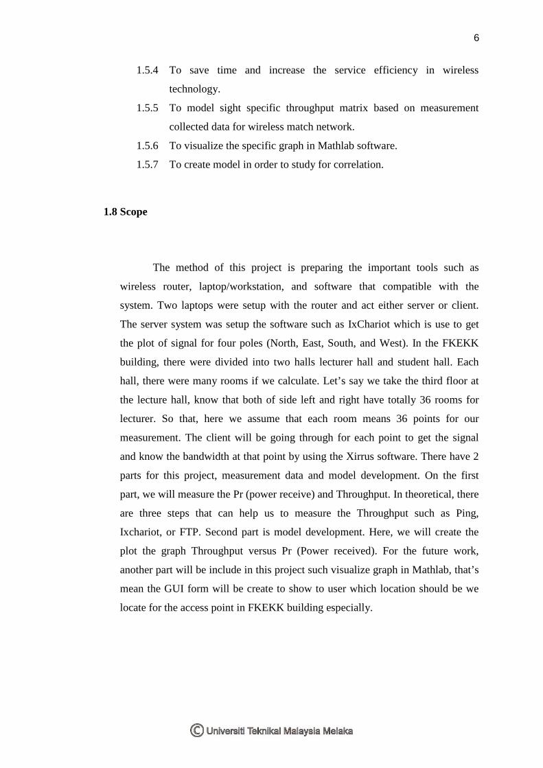
1.8 Scope
The method of this project is preparing the important tools such as
wireless router, laptop/workstation, and software that compatible with the
system. Two laptops were setup with the router and act either server or client.
The server system was setup the software such as IxChariot which is use to get
the plot of signal for four poles (North, East, South, and West). In the FKEKK
building, there were divided into two halls lecturer hall and student hall. Each
hall, there were many rooms if we calculate. Let’s say we take the third floor at
the lecture hall, know that both of side left and right have totally 36 rooms for
lecturer. So that, here we assume that each room means 36 points for our
measurement. The client will be going through for each point to get the signal
and know the bandwidth at that point by using the Xirrus software. There have 2
parts for this project, measurement data and model development. On the first
part, we will measure the Pr (power receive) and Throughput. In theoretical, there
are three steps that can help us to measure the Throughput such as Ping,
Ixchariot, or FTP. Second part is model development. Here, we will create the
plot the graph Throughput versus Pr (Power received). For the future work,
another part will be include in this project such visualize graph in Mathlab, that’s
mean the GUI form will be create to show to user which location should be we
locate for the access point in FKEKK building especially.

7
1.9Thesis Outline
1.9.1 Chapter 1 – Introduction
This chapter is about the introduction of Indoor Radio Propagation
which is already state a few subtitle that we must know in this project.
The basic radio propagation was already explained and clearly about
specification for this project. Then, know about the multipath that
occurred in the wireless transmission. The phenomenon of reflection,
diffraction and scattering all give rise to additional radio propagation
paths beyond the direct optical "line of sight" path between the radio
transmitter and receiver.
1.9.2 Chapter 2 – Literature Review
This chapter is about the software that we use in this project. The
Theoretical Study will be discussing on some related theories and
explanations on each equipment used in this project. Fact and finding
is the formal process to collect and capture the entire information
about system, system requirements and system preferences. In
addition, information source can be gathered in formal sources and
informal sources. For formal sources the information can be gathered
from books, journal, research papers, encyclopedias, newspapers,
magazines, handbooks, thesis, bibliographies and World Wide Web
(WWW).
1.9.3 Chapter 3 – Methodology
This section will describe the flow of this project. It is an important
criterion for this project. This chapter discussed about procedures that
will use in this project. It begins by choosing a topic of project,
research and finally completing by developing the system. The purpose

8
in this chapter is to implement this system smoothly and follow the
planning that has been decided.
1.9.4 Chapter 4 – Result and Discussion
This Chapter presents the measurement results were obtained from
extensive measurement. To present this data in an orderly format,
MATLAB plots are used. The MATLAB plots presented throughout
this chapter are arranged with the measured signal to noise ratio for
the desired link from the client to the access p on the x axis and the
measured throughput on the y axis. We must know about the physical
locations that will be affected to our measurement. Then, know about
the measurement purpose and know how to setup or our planning to
measure and collect the data measurement. The presented plots of the
measurements show a definite correlation between the signal to noise
ratio, and to some small degree, to the net interference power. These
relationships are clearest the window averaged plots that have been
presented.
1.9.5 Chapter 5 – Conclusion and Suggestion
This chapter are consists two subtopics which are the conclusion as
well as the recommendation towards this project. This conclusion will
present about the most important points in this project as well as the
success part that has been achieved during the implementation process
while recommendation presents about what are the new suggestions
that can be implemented in this project for the future undertaking
action. To develop this project, it must be considered to the research
element as the main point. So, all about statement and proof of
research element in this part are look toward the research element for