
Indoor Gas Heating Products - Trane - Heating and Air ... Gas Heating Products Unit Heaters Duct...
68
Indoor Gas Heating Products Unit Heaters Duct Furnaces UH-PRC002-EN February 2001
Transcript of Indoor Gas Heating Products - Trane - Heating and Air ... Gas Heating Products Unit Heaters Duct...

Indoor GasHeating Products
Unit Heaters
Duct Furnaces
UH-PRC002-ENFebruary 2001

©American Standard Inc. 2001 UH-PRC002-EN
Introduction
Trane unit heaters represent atechnological breakthrough in quality.Trane offers customers the mostcomplete line of unit heaters anywhere.And every unit in the line has been ratedfor 80 percent thermal efficiency orbetter.
But higher thermal efficiency and loweroperating costs are just two features ofthis product line. Innovation — theengineering advances you’ve come toexpect from Trane — can also be foundacross this entire line of unit heaters.And rugged, quality constructionprovides years of dependable service.
Quality products mean Trane value.So does fair, competitive pricing. The 10-year warranty tells you Trane will be herefor the long haul — keeping ourcommitment to you. You can count onTrane standing behind every unitshipped. That is what Trane value means.

3
Contents
UH-PRC002-EN
Introduction
Feature Highlights
Features and Benefits
Application Considerations
Selection Procedure
Manual Selection ProcedureModel Number Description
General Data
Performance Data
Adjustment Factor
Controls
Electric Power
Dimension and Weights
Mechanical Specifications
2
4
5
8
16
161719
21
21
27
29
41
57

UH-PRC002-EN4
FeaturesHighlights
Ten-Year Warranty
The complete heat exchanger, draft hoodassembly of the unit heater and burnersare warranted by Trane to be free fromdefects in material and workmanship fora period of 10 years from the date ofmanufacture. (Warranty not applicableon duct furnaces or SeparatedCombustion units.)
Quiet Operation
Trane unit heaters incorporate anexceptionally balanced fan blade toassure quiet operation.
Heat Exchangers
All Trane heat exchangers are available inthree types of steel:• Aluminized Steel (Standard)• 409 Grade Stainless Steel (Optional)
(30-400 MBh units)• 321 Grade Stainless Steel (Optional)
(100-400 MBh units)
24V System
All units are equipped with a 24Vcontrolsystem which is powered by a 24Vtransformer as standard equipment.
Fan Time Delay
The fan time delay is mounted at thefactory as standard equipment (optionalon duct furnaces). This feature eliminatesan initial blast of cold air by allowing theunit to fire for a short period of timebefore actuating the fan motor. After thethermostat is satisfied (with burners off),the fan continues to operate forapproximately one minute, removingresidual heat from heat exchanger.
Burners
All sizes 30,000 through 400,000 Btuinput are equipped with a provendesign pressed steel burner having aunique “burner shade” protectivedevice to prevent scale or foreignmatter from plugging the burner ports.
Energy Saving Intermittent Pilot Control
The pilot burner is ignited only duringeach cycle of operation, therebyconserving energy during the off cycle.
LP/Natural Operation
All units are available for operation oneither natural or LP gas from ourfactory.
Easy Access For Maintenance
All Trane unit heaters are so designedthat the burner access panel is removedwith just two screws. Burners areindividually removable for inspectionand servicing. Pilot is also accessiblethrough side panel access door.
Test Fired
All Trane unit heaters are test fired toassure proper operation.
Ideal For Retrofit
Trane unit heaters let you pocket fuelsavings from day one and provideyears of dependable service.

5UH-PRC002-EN
Features andBenefits
High-Efficiency Propeller
Fan Unit Heaters
Trane high-efficiency propeller fan unitheaters achieve annual fuel savings of20 to 25 percent over conventionalgravity vented heaters.Each unit features a factory-installedflue vent fan and sealed flue collectorthat controls combustion and excessair during the on-cycle.
Heated air no longer escapes throughthe draft diverter opening during theoff-cycle. Energy saving intermittentpilot ignition reduces gas losses. Thepilot only operates when required.
Horizontal power venting, smalleropenings and single-walled vent pipereduce heat loss. Higher efficienciescan reduce equipment and materialcosts as well as installation time.
High Efficiency Indoor Duct Furnace
The high efficiency indoor gas ductfurnace complements our currentcentrifugal and propeller fan lines.All high efficiency lines were designed toachieve fuel savings of up to25 percent over conventional gravityvented heaters.
Conventional gravity vented heaters lostheated room air through the draftdiverter opening. The high efficiency linefeatures an integral flue vent fan andsealed flue collector for improvedcombustion. It reduces air requirementsand wind effects on the system’sefficiency. Intermittent pilot ignitionreduces pilot gas losses and the flue ventfan allows for horizontal venting throughside walls.
DUCT FURNACES ARE APPROVED FORBLOW-THRU APPLICATIONS ONLY.
High-Efficiency Centrifugal
Fan Unit Heaters
The high-efficiency centrifugal fan unitheater keeps energy costs down. Thedesign advances achieve annual fuelsavings of 20 to 25 percent overconventional gravity vented heaters.
In the past, these conventional gravityvented heaters lost heated room airthrough the draft diverter opening.
The high-efficiency centrifugal unitfeatures integral power venting (factory-installed) and sealed flue collector foroptimum combustion.It reduces wind effects on the system’sefficiency. Intermittent pilot ignitionreduces pilot gas losses and the powerdrafter allows for horizontal ventingthrough side walls. It all adds up tohigher efficiencies and lower installationcosts.

UH-PRC002-EN6
Features andBenefits
Separated Combustion Propeller FanUnit Heaters
Separated Combustion Centrifugal FanUnit Heaters
The Trane separated combustion unitsare designed for space heating in mildlyhostile environments. These units can beinstalled where dusty, dirty, or mildlycorrosive conditions exist or where highhumidity or slightly negative pressureprevail.
Typical applications are industrial workareas with wood or textile dust, non-explosive contaminated environments,non-chlorine process areas, automotiveand truck garages and greenhouses.
Centrifugal Fan Unit Heaters
Centrifugal fan unit heaters are ideal forcommercial and industrial applicationswhere a low noise level is desired. Tranecentrifugal fan unit heaters whichoperate at .2-inches W.C. are extremelyquiet.
Centrifugal fan gas-fired unit heatersshould be selected for applicationswhere ductwork or discharge nozzles areto be used.
Propeller Fan Unit Heaters
The Trane gas-fired unit heater is acomplete heat generating anddistributing plant, equipped withautomatic safety controls, all packaged ina modern, streamlined, space saving,attractive casing for mounting near theceiling. Propeller units are basically zerostatic pressure appliances. At no timeshould ductwork be used with propellerunits.
The designs are certified by AGA andCGA as conforming with standards forsafe and efficient performance.
These units achieve higher seasonalefficiencies by using outside air forcombustion, overcomes slight negativepressures near exhaust fans or paintbooths and isolates burner from dust,
humidity and chemicals. The combustionprocess is separate from theenvironment where the unit is installed.A power venting system draws acontrolled quantity of combustion air
from outside the building. The samesystem exhausts flue products to theoutside. The burners, pilot and fluesystem are enclosed within the unit, thusthe whole combustion process is literallyunaffected by the atmosphere where theheater is located.
7UH-PRC002-EN
Features andBenefits
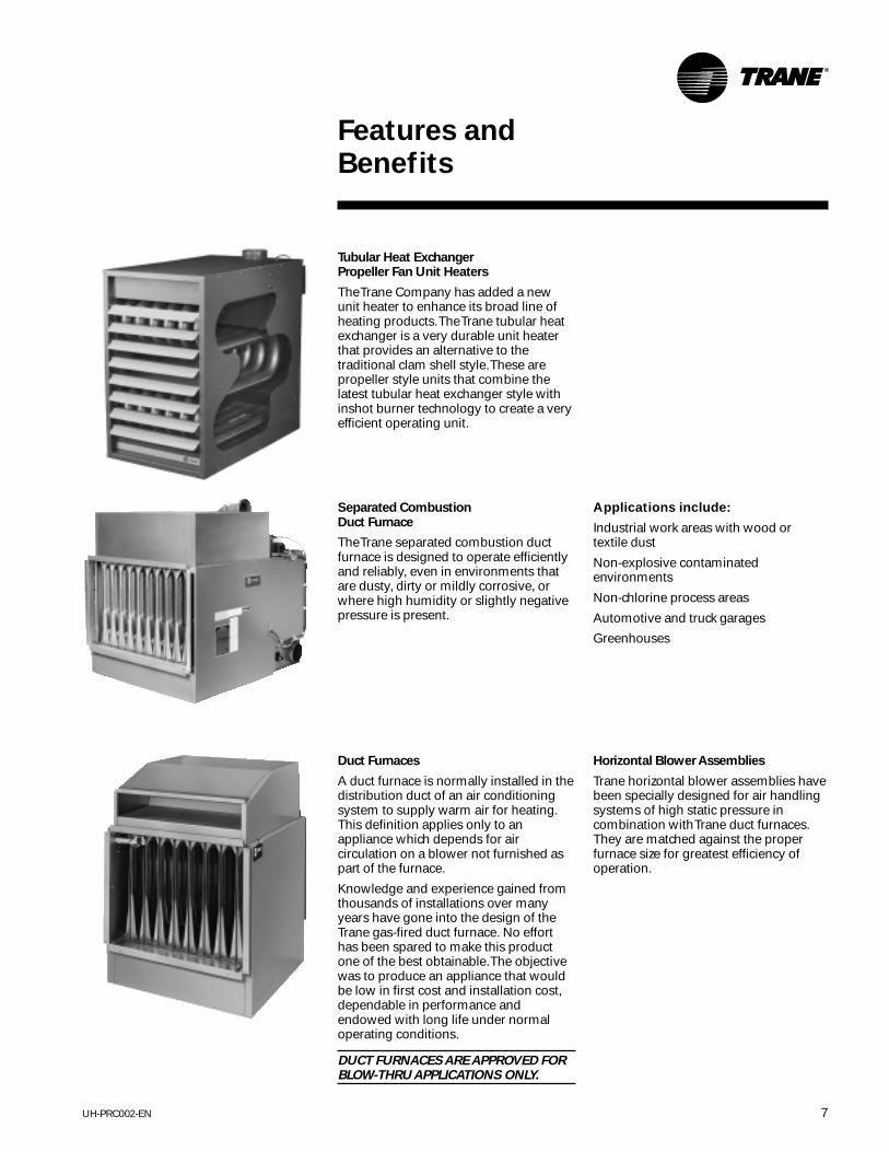
Tubular Heat ExchangerPropeller Fan Unit Heaters
The Trane Company has added a newunit heater to enhance its broad line ofheating products. The Trane tubular heatexchanger is a very durable unit heaterthat provides an alternative to thetraditional clam shell style. These arepropeller style units that combine thelatest tubular heat exchanger style withinshot burner technology to create a veryefficient operating unit.
Duct Furnaces
A duct furnace is normally installed in thedistribution duct of an air conditioningsystem to supply warm air for heating.This definition applies only to anappliance which depends for aircirculation on a blower not furnished aspart of the furnace.
Knowledge and experience gained fromthousands of installations over manyyears have gone into the design of theTrane gas-fired duct furnace. No efforthas been spared to make this productone of the best obtainable. The objectivewas to produce an appliance that wouldbe low in first cost and installation cost,dependable in performance andendowed with long life under normaloperating conditions.
DUCT FURNACES ARE APPROVED FORBLOW-THRU APPLICATIONS ONLY.
Separated CombustionDuct Furnace
The Trane separated combustion ductfurnace is designed to operate efficientlyand reliably, even in environments thatare dusty, dirty or mildly corrosive, orwhere high humidity or slightly negativepressure is present.
Horizontal Blower Assemblies
Trane horizontal blower assemblies havebeen specially designed for air handlingsystems of high static pressure incombination with Trane duct furnaces.They are matched against the properfurnace size for greatest efficiency ofoperation.
Applications include:
Industrial work areas with wood ortextile dust
Non-explosive contaminatedenvironments
Non-chlorine process areas
Automotive and truck garages
Greenhouses

UH-PRC002-EN8
ApplicationConsiderations
natural gas is not available, Trane unitsmay be ordered directly from the factoryfor use on LP (propane) gas.
Gas heat content varies by fuel type andlocation. The standard gross heatingvalue for natural gas is 1,000 Btu percubic foot, and for propane, 2,500 Btuper cubic foot. Significant variationsselections. To account for variations inthe gross heating value of the fuel, adjustthe total heat input required and selectthe unit on the basis of the adjusted loadusing the following formula:
Adjusted load = Calculated load xgross heat value (Btu/cu ft)
Actual gross heat value (Btu/cu ft)
Low Temperature Rise
Trane recommends against the setup ofa unit which will result in a temperaturerise of less than 30°F. With such lowtemperature rises, the flue gases passingthrough the heat exchanger are cooledto condensate before reaching the flueoutlet. This condensate is corrosive andwill result in shortened heat exchangerlife.
Air Density
Catalog performance data is based onelevations up to 2,000 feet above sealevel. Above 2,000 feet the unit’s heatingcapacity must be derated four percentfor each 1,000 feet above sea level, andspecial orifice selections are required.Table PAF-1 contains correction factorsthat can be applied to the unit’scataloged heating capacity, fan rpm, andfan bhp to obtain actual values forelevations above 2,000 feet.
Corrosive Atmospheres
Corrosion of heat exchangers and draftdiverters have two basic variables –moisture (condensation) and sulphur.These two ingredients form to makesulfuric acid in the combustion process.Condensation occurs commonly inmakeup air systems, using largeamounts of fresh air, when airtemperatures entering the heatexchanger drop to 40°F or below. Thisreaction can also occur in recirculatingsystems where some quantity of outsideair is introduced upstream of theexchanger. The sulphur will always bepresent as an integral component of the
gas. The resulting concentration of theacid is governed by the amount ofsulphur in the gas. This concentrationvaries from gas to gas andgeographically within the same typeof gas.
Beyond sulfuric acid corrosion there isthe area of chlorinated or halogenatedhydrocarbon vapor corrosion. This typeof corrosion occurs when substances aremixed with combustion air that willcause the formation of hydrochloric orhydrofluoric acid when burned. Thesebasic substances are found indegreasers, dry cleaning solvents, glues,cements, paint removers and aerosolpropellants. Specific chemicals includedin this group are trichloroethylene,perchloroethylene, carbon tetrachloride,methylene chloride, methyl chloroformand refrigerants 11, 12, 21, 22 and 114.
If sufficient PPM content of thesecorrosives is present, none of thecommon heat exchanger materials willhold up. The dilemma becomes whetherto place the gas heating equipmentoutside of the area to be conditioned, oruse equipment in the space which doesnot burn a fuel such as gas (i.e. electric orhydronic).
Units should not be installed in areaswith corrosive or inflammableatmospheres. Locations containingsolvents or chlorinated hydrocarbonswill produce corrosive acids whencoming in contact with burner flames.This reaction will greatly reduce the lifeof the heat exchanger and may void thewarranty. For added protection againstheat exchanger corrosion, optional 409and 321 stainless steel construction isavailable. On units using outside air, withentering air temperature below 40°F,condensation of flue gas in the heatexchanger is possible. In these cases,stainless steel heat exchangers arerecommended.
Careful review of the job application withrespect to use, probable contaminantswithin a conditioned space or theamount of fresh air to be brought in, willhelp to make the proper selection of heatexchanger material. This review will helpto eliminate problems before they begin.
NOTE: When installing duct furnaces inparallel or in series, minimum clearancerequirements must be considered. This isrequired for serviceability of the gasvalve and the high limit. “All ductfurnaces are approved in blow-thruapplications only.”
All duct furnaces are AGA approvedupstream or downstream of the coolingcoil. Recommend optional field installeddrain pan when installed on thedownstream side of the cooling coil.
NOTE: Downstream denotes cooling coilahead of the fan section.
When used in conjunction with filters,cooling coils and an air handler, the duct
furnace can become part of a built-upheating and cooling system.
Gas Heating Value
The majority of gas heating units areinstalled in applications where naturalgas is readily available. In areas where
General
Propeller fan unit heaters and centrifugalfan unit heaters are designed for use inspace heating applications. The units aretypically used in areas with high ceilings,and are exposed in the space to beheated. Unit heaters offer low installedcost, and are able to heat large volumeareas without requiring extensive ductsystems.
Duct furnaces are designed for use inducted applications with a separate airhandling device such as a horizontalblower assembly. By utilizing a separateair source, greater application flexibilityin airflow delivery can be obtained.Multiple duct furnaces can be used withan air handling unit to provide zoneheating.

9UH-PRC002-EN
ApplicationConsiderations
Indoor Units
Indoor gas unit heaters and ductfurnaces are used primarily incommercial and industrial structuressuch as manufacturing areas,warehouses, garages, stores,showrooms, lobbies and corridors.
Separated combustion units are usedprimarily in industrial work areas withwood or textile dust, non-explosivecontaminated environments, non-chlorine process areas, automotive andtruck garages and greenhouses.
Unit Placement
Refer to the applicable Trane Installation,Operation and Maintenance literature forspecific installation instructions.Installations must conform with localbuilding codes or in the absence of localcodes with the National Fuel Gas CodeANSI Z223.1.
When selecting a location for an indoorunit heater, both the size and weight ofthe unit, as well as the heatingrequirements of the building, should beconsidered. Installation of units inairplane hangars or public garagesshould be in accordance with NFPA No.409 for aircraft hangars, and NFPA No.88 for garages.
For proper distribution, air should bedirected towards areas of maximumheat loss. When multiple units are used,circulation of heated air around thespace perimeter is recommended.Satisfactory results can also be obtainedwhere multiple units are located towardthe center of the area, with heated airbeing discharged toward the outsidewalls. Throw data for standard unitheaters and unit heaters utilizingoptional discharge nozzles is shown inthe General Data section, pages 19 and20.
Locations where extreme drafts canaffect burner operation should beavoided. Strong drafts may cause pilotoutage. Units with intermittent pilotignition may be preferable in areaswhere drafts are likely.
Minimum clearances required foraccessibility and safety are listed in TableGD-1.
Throw Data
Throw data for units with standardlouvers and for units with optionaldischarge nozzles are in the General Datasection, pages 19 and 20. Optionalnozzles are for use on propeller fan unitheaters, centrifugal fan unit heaters andduct furnaces. When greater throwdistance is desired, a 45° nozzle isrecommended. For high mountingheights, a 90° nozzle may be used. Whenwide diffusion is needed, a Y splitternozzle should be considered. A five-waynozzle can be used for applicationsrequiring even air distribution over alarge floor area. (Five-way nozzles arenot available on propeller fan unitheaters.)
Indoor Units — Venting
Gas fired indoor units require venting toremove the products of combustion. Tohelp assure safe, trouble-free operation,follow the guidelines listed below:
Natural Venting1Provide a vertical flue of at least four feet.2Use a flue the same size as the flueopening on the unit.3Provide maximum vertical rise at theunits.4Keep horizontal runs to a minimum andslope flue upward at least ¼-inch perfoot. Horizontal runs should notexceed 75 percent of the verticalheight of the vent pipe, or chimney,above the flue pipe connection.5Avoid short turns; 45° elbows arerecommended.6The vent pipe should be at least sixinches from combustible material andshould be properly insulated whenpassing through combustible partitions.7Extend flue at least two feet above thehighest point of the roof.8Tape flue pipe joints with fireproof paperor material.
9Avoid installing units in areas undernegative pressure.10Avoid running vent pipe throughunheated spaces. When this cannot beavoided, insulate the pipe to preventcondensation of moisture on the insidewalls of the pipe.11Where two or more units vent into acommon flue, the cross-sectional area ofthe common flue must be equal to thelarger vent connection plus 50 percent ofthe area of each additional ventconnection. (Gravity vent units only.)12Do not damper the flue piping. Failure toopen such a damper prior to operatingthe unit will result in the spillage of fluegas into the occupied space, activatingthe blocked vent (spill) switch.
Flue Vent Fans
Where chimneys of sufficient height areimpractical, or where the distance fromthe heater to the chimney is so great thatsufficient draft cannot be created, a fluevent fan can be used to vent theproducts of combustion. The flue ventfan is normally started and stopped bythe room thermostat. A centrifugalswitch in the flue vent fan operates theelectric gas valve.
Dimensional data for the flue vent fan isshown in Table DW-14.

UH-PRC002-EN10
ApplicationConsiderations
Power Vented Units
Units with a factory installed flue ventfan.1All units must be vented. Power ventedunits are designed to use single wallventpipe. A Breidert Type L, Field Starkap, orequivalent unit vent cap must befurnished by the customer.2The venting system for these appliancesshall terminate at least 4 feet below, 4feet horizontally from, or 1 foot aboveany door, window or gravity air inlet intoany building.3Through-the-wall vents for theseappliances shall not terminate overpublic walkways or over an area wherecondensate or vapor could create anuisance or hazard or could bedetrimental to the operation ofregulators, relief valves, or otherequipment.4The vent pipe diameter must be asshown under “Recommended Flue Size”in the specification charts. An adaptormust be field supplied if required.5Each furnace must have anindividual vent pipe and ventterminal. Vent pipe equivalent lengthmust not exceed 50 feet. Equivalentlength is the total length of straightsections, plus 15 feet for each 90°elbow and 8 feet for each 45°elbow.6Maintain 6 inch clearance between ventpipe and combustible materials. Ventterminal must be installed with aminimum clearance of 4 feet fromelectric meters, gas meters, regulators,and relief equipment.7Seal vent pipe joints to prevent leakage.Use General Electric RTV-108 or DowCorning RTV-732 Silicone Sealant or 3M#425 aluminum foil tape.
8Pitch horizontal pipes downward¼-inch per foot toward outlet forcondensate drainage. Horizontalportions of the venting system shall besupported at maximum intervals of4 feet to prevent sagging.9Vertical vent pipes should be equippedwith condensate drains.10Insulate single wall vent pipe exposedto cold air or running throughunheated areas.
FM and IRI Requirements
IRI, which stands for Industrial RiskInsurers, and FM, which stands forFactory Mutual, are both basicallyinsurance companies which insurecommercial/industrial firms against avariety of losses. Both publishrequirements which must be met bycertain equipment operating in thefacilities they are preparing to insure.
Listed below is our interpretation of therequirements of both insurers pertainingto heating units only to the extent offeatures/controls required by IRI and/orFM. There are a number of additionalrequirements which pertain to electricalservice, details of installation, etc., andwe urge you to obtain copies of thepublications pertaining to these details ifyou are involved in a job where IRI or FMadherence has been indicated. Therequirements detailed herein are ourinterpretations of the latest publicationsin our possession and we must disclaimany responsibility for errors due to ourinterpretation and/or lack of any updatedrevision of these standards. Our intent isto provide you with an understanding ofthe application of these standards andhow we believe our indirect-fired gasheating equipment applies.
IRI Requirements1All input sizes require 100 percentshutoff. This requires that any natural gasunit, equipped with intermittent pilotignition, must employ a “lock out” typeignition system which will shut off pilotgas if the pilot fails to light at any time.This system is required by AGA on LPgas units as standard equipment.However, for natural gas units, you needto specify on the order “Natural Gas, 100percent shutoff.”2All units require AGA certification or UL“listed” controls. Our units are AGAcertified and meet this requirement.3Models with inputs of 150,000 to 400,000Btu require “mechanical exhaust” anda “safety interlock.” For our units thismeans a power vented or drafterequipped unit. In both instances, if theflue vent fan (factory or field installed)does not get up to speed, the unit willnot fire, satisfying the safety interlockportion.
FM Requirements1All units must be AGA certified or ULlisted. Our units are AGA certified.2The high limit control must be in acircuit, the voltage of which does notexceed 120 VAC. All of our high limitswould meet this requirement.
The specific requirement for an “IRI orFM Gas Train,” while it applies to directand indirect-fired gas heating equipmentas well as oil-fired, comes into play onlywith units having an input in excess of400,000 Btu. This may be one of thereasons why the majority of gas heatingequipment manufacturers (indirect-fired)limit their largest individual furnace to400,000 Btu.

11UH-PRC002-EN
ApplicationConsiderations
High Pressure Regulators —
Natural Gas Only
The Trane indoor gas heating productscontained in this catalog, are designedto operate at a pressure of 3.5-inch W.C.(Water Column) when firing on naturalgas. This is the “manifold” pressure orthat which is present at the burnerorifices. All five and six-function valvesprovide a built-in pressure regulatorwhich is capable of reducing “supply”pressures from a maximum of 14-inchW.C. (½ psi) down to3.5-inch W.C. on the leaving side of thevalve. The valve typically “drops” about1½-inch so the minimum supplypressure is 5-inch W.C.
Whenever supply pressures exceed14-inch W.C., a high pressure regulatorshould be selected. We supply aRockwell regulator which is fitted withpressure springs and capacity orificingto meet the requirements of eachspecific job.
Table AC-1 — Orifice Chart: Rockwell 043-182 Regulator
Inlet Capacity in MBH for Natural Gas SpringPressure 25-200 225-300 350-500 600 700 800 Required1 psi 3/8” N/A N/A N/A N/A N/A Blue (only)2 3/8” 3/8” N/A N/A N/A N/A Blue (only)3 3/8” 3/8” 3/8” N/A N/A N/A Blue or Green5 3/8” 3/8” 3/8” 3/8” 3/8” 3/8” Blue or Green
10 3/8” 3/8” 3/8” 3/8” 3/8” 3/8” Blue or Green20 1/4” 1/4” 1/4” 1/4” 1/4” 5/16” Blue or Green40 1/4” 1/4” 1/4” 1/4” 1/4” 1/4” Blue or Green60 1/8” 1/8” 1/8” 1/8” 1/8” 3/16” Blue or Green80 1/8” 1/8” 1/8” 1/8” 1/8” N/A Blue or Green
100 1/8” 1/8” 1/8” 1/8” 1/8” 1/8” Blue or Green125 1/8” 1/8” 1/8” 1/8” 1/8” 1/8” Blue or Green
In order to select the proper spring/orifice combination, we need to knowwhat the supply pressure is on thatparticular job and the input size of theunit being ordered. More than one unitcan be run from one regulator; however,we recommend that each unit have itsown regulator.
We require that the “job” supplypressure be included on all jobsrequiring high pressure regulators alongwith the unit size. The table that followsdisplays the regulators range as itpertains to inlet pressure and MBh. N/Arequires the customer to contact a localutility or an industrial supply house.
These devices are not available fromTrane for LP gas. LP accessories must besecured from the gas supplier/ supplyhouse.
Minimum/MaximumGas Inlet Pressures
Gas valves are suitable to a maximuminlet pressure of 0.5 psi (14 inches watercolumn) on natural gas. If the main gassupply pressure is greater than14 inches W.C., a step-down pressureregulator must be field installed ahead ofthe gas valve. Minimum inlet pressure fornatural gas units is 5 inches W.C.
For LP (propane) gas, the minimum inletpressure is 11.0 inches W.C.and the maximum inlet pressure is14.0 inches W.C.

UH-PRC002-EN12
ApplicationConsiderations
Mounting Detail(Hanging Hardware Supplied by Others)
Steel Construction
Wood Construction

13UH-PRC002-EN
ApplicationConsiderations
(VentingUnit Heaters)
Venting unit heaters and duct furnacesused to be as simple as rememberingthat warm air rises. With the introductionof new venting equipment and safetycontrols, things have become a littlemore technical. Today’s contractor has toknow a lot more about proper venting toget the job done within code at areasonable price.
For starters ANSI now categorizes ventedappliances into four categories. CategoryI includes non-condensing applianceswith negative vent pressure, like thetraditional atmospheric unit heater.
Venting Categories
Non-Condensing CondensingNegativeVent Pressure I IIPositiveVent Pressure III IV
Category II groups condensingappliances with negative vent pressure.
Category III appliances are non-condensing and operate with a positivevent pressure, like the traditional powervented unit heater. Category IV coverscondensing appliances with positive ventpressure.
Tie smaller units into larger. Avoid cross
connections that feed backwards into
another flue.
Sharing Flues with Other Appliances
Traditionally unit heaters get installed inpairs, sharing a common flue betweentwo heaters. When a unit heater mustshare a flue with another appliance a fewcautions are appropriate.
Always be certain that the flue canhandle the combined operation of allappliances connected to it. Neverassume that one appliance will operateat a time. When connecting into the stackor breaching always connect the devicewith the largest input first. This limits thepotential for flue gases to escape outother outlets and warms the entirechimney. Avoid installing appliancesdirectly across from each other whenentering the stack. This might force thedraft from one appliance to vent out theopposing draft diverter.
When piping to a stack NEVER reducethe appliance vent size. Use smoothtransitions and long bends. Abrupttransitions and tight elbows createresistance and turbulence that can limitvent capacity. Never connect powervented devices to common flues.Mechanically vented appliances musthave dedicated vents to the point oftermination.
Spill Switch
Problems arise in buildings that haveexperienced back drafting from negativepressure for years. As new units replaceold, the back drafting causes the units toshutdown, uncovering a makeup airproblem that has gone uncorrected foryears.
Natural Draft Unit Heaters
The gravity vented unit heater still hasthe greatest acceptance, but the newhigh efficiency of gravity unit heaters addsome new twists to venting. As efficiencyrises more heat gets extracted from theflue gas. This heat had been driving thevent system in natural draft systems.With lower flue gas temperatures,velocities in the chimney decrease. Inturn this lower velocity can cause fluegases to reach the point at which theywill condense.
When a factory owner replaces an oldunit heater, having an efficiency of65 percent, he expects to benefit fromthe higher efficiency of the new unit. Thisefficiency brings a system change with itin the form of lower flue temperatures,closer to the dewpoint.If the old stack isn’t corrosion resistantdeterioration may be sudden. The mildacid that forms when vent gascondenses will gradually eat away at themetal. Eventually the stack will rustthrough leaking fumes andcondensation.
To avoid condensation be certain to usestacks of the right size. Oversize stacksdraw slower, allowing more time forcondensation. For naturally vented unitsuse B vent. This insulated vent pipecontains vent heat, reducing the chancesof condensation. This is particularlyimportant for vents running throughunheated areas.
In addition to problems fromcondensation, contractors have had tobecome aware of new mandatedcontrols. In addition to a high limitswitch, the primary power circuit fornaturally vented atmospheric gas unitheaters now contains a “spill” switch.This switch, a manually resettablethermo disk type device, senses ablocked flue. Sensitive to a rise intemperature in the draft diverter, the spillswitch cuts off power to the gas valvestopping combustion.
UH-PRC002-EN14
ApplicationConsiderations
(VentingUnit Heaters)
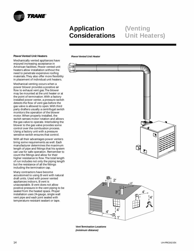
Power Vented Unit Heaters
Mechanically vented appliances haveenjoyed increasing acceptance inAmerican facilities. Power vented unitheaters allow installation without theneed to penetrate expensive roofingmaterials. They also offer more flexibilityin placement of individual unit heaters.
Mechanical venting occurs when apower blower provides a positive airflow to exhaust vent gas. The blowermay be mounted at the unit heater or atthe point of termination. With a factoryinstalled power venter, a pressure switchdetects the flow of vent gas before thegas valve is allowed to open. With thirdparty drafters usually a centrifugal switchmonitors the operation of the blowermotor. When properly installed, theswitch senses motor rotation and allowsthe gas valve to operate. Interlocking theblower to the gas valve provides somecontrol over the combustion process.Using a factory unit with a pressuresensitive switch ensures that control.
With all their advantages power ventersbring some requirements as well. Eachmanufacturer determines the maximumlength of pipe and fittings that his systemcan use for safe operation. Remember tocount the fittings and allow for theirhigher resistance to flow. The total lengthof run includes not only the piping lengthbut the resistance of all the fittingsincluding the termination cap.
Many contractors have becomeaccustomed to using B vent with naturaldraft units. Used with power ventedappliances indoors, B vent isunacceptable. B vent does not allowpositive pressure in the vent piping to besealed from the heated space. Properinstallation uses 24-gauge, single wallvent pipe and each joint sealed withtemperature resistant sealant or tape.
Power Vented Unit Heater
Vent Termination Locations
(minimum distance)

15UH-PRC002-EN
ApplicationConsiderations
Heat
Fumes
Humidity
Contractors must also be aware of theconditions at the point of termination.The National Fuel Gas Code NFPA 54/ANSI Z223.1-1992 mandates that ventsystem should terminate at least 4 feetbelow, 4 feet horizontally or 1 foot aboveany window, door, or gravity inlet to abuilding. Termination with a vent capapproved by the manufacturer shouldoccur well above the snow line.
Beyond satisfying the codes, ventsshould be positioned away from shrubsand plants that might be affected byunseasonable warming by the exhaust.Sidewall vents release a considerableamount of water vapor that maycondense on cold siding, adverselyaffecting painted surfaces. Placing thesevents in locations that get natural aircirculation from prevailing winds mayhelp to reduce these negative effects.
Separated Combustion Venting
Another form of mechanical ventingincludes those unit heaters that use apowered exhaust also to pull in outsideair. Most often found on condensingfurnaces, separated combustion doesnot use room air for combustion. Insteadthese unit heaters use a second run ofpipe to supply fresh outdoor air.
The separated combustion approachoffers several advantages. First, it doesnot use warm indoor air to fire the unitheater. This saves energy by avoidingdrawing unheated make-up air into theliving space. Second, the unit heater hasan unlimited source of air forcombustion. In many of the new superinsulated buildings appliances can bestarved for combustion air. Incontaminated atmospheres the use ofseparated combustion unit heatersassures that the heat exchanger seesonly non-corrosive air.
When positioning the intake and exhaustvents on separated combustionequipment, the intake and outlet mustmount on the same outside surface. Thisensures that any wind effects balanceout. Remember to keep the vents at least18” apart to avoid drawing exhaust airinto the intake air.
With Trane’s separated combustion unitheaters intake air and exhaust air runthrough standard 24-gauge galvanizedpipe. Remember that separatedcombustion unit heaters still have highvent temperatures. Use of PVC, CPVCand other plastic vent materials areinappropriate and hazardous. Check themanufacturer’s instructions beforepiping any appliance.
The vent gases of power vented andseparated combustion unit heaters maycondense on a cold start-up or whenvent piping runs through unheatedareas. To protect the heater always pitchboth intake and exhaust piping towardthe outside of the building. Rememberalso that no power vented equipmentcan share a common flue with any otherappliance. Should a flue become blockedone appliance could vent into theoccupied space.
Approved vent caps should be used onboth the intake and exhaustterminations. For greater convenienceTrane offers a concentric vent adapterthat allows venting through a singleperforation through the building wall orroof.
Opportunities Using Trane Gas Products
Whatever venting configuration your jobrequires, Trane offers a unit heater tomeet your needs. Trane offers thereliability of traditional standing pilotsystems, always vented by natural draft.We offer spark ignition natural draft andpower vented unit heaters and the newseparated combustion unit heaters.
(VentingUnit Heaters)

UH-PRC002-EN16
SelectionProcedure
Determine the total heating loadrequirements in accordance withmethods recommended by the ASHRAEHandbook of Fundamentals or otheracceptable means.
Propeller Fan Unit Heater1From the performance data tables, selectthe unit whose heating output meets orexceeds the heating load requirement.2Airflow (cfm) and temperature rise canbe read directly from the performancedata tables.3Knowing the mounting height of theunit, throw can be determined from theperformance data table. If the throw isnot adequate, consider using a largerpropeller fan unit heater or a centrifugalfan unit heater with an optionaldischarge nozzle for greater throw.
Selection Example —A natural gaspropeller fan unit heater that can provide75 MBh heating output is required. Theunit will be mounted 10 feet above thefloor and a 40-foot throw is required.
Select the unit as follows:aFrom Table PD-5, select a GPND-010 witha 100.0 MBh input and 80.0 MBh heatingoutput, 1,480 cfm and a 50°Ftemperature rise.bFrom Table GD-2, throw at a mountingheight of 10 feet is 54 feet.
Centrifugal Fan Unit Heater1From the performance data tables, selectthe unit whose heating output meets orexceeds the heating load requirement.2Airflow (cfm) ranges are listed for eachunit size in the performance data tables.Knowing either the desired airflow ortemperature rise, the other can becalculated using the following formulas:
cfm = Output x 1,000 1.085 x ∆T
∆T = Output x 1,000 1.085 x cfm
3Knowing the mounting height of theunit, throw can be determined from theperformance data table. If the throw isnot adequate, a discharge nozzle can beused to obtain additional throw.
Selection Example —An LP (Propane)gas centrifugal fan unit heater that canprovide 150 MBh heating output isrequired. An airflow of 2,000 cfm isdesired. The unit will be mounted 12 feetabove the floor and a 65-foot throw isrequired.
Select the unit as follows:aFrom Table PD-7, select a GCPD-020 witha 200.0 MBh input and 160.0 MBhheating output. An airflow of 2,000 cfmis within the allowable range, andtemperature rise is calculated as follows:
∆T = MBh x 1,000 1.085 x cfm
∆T = 160 x 1,000 = 74.0°F1.085 x 2,000
bFrom Table GD-2, throw at a 12-footmounting height is 61 feet. As a 61-footthrow is not adequate, a 60 degreenozzle can be selected (from TableGD-4) which provides a throw of76 feet.
Duct Furnace1From the performance data tables, selectthe unit whose heating output meets orexceeds the heating load requirement.2Given the airflow to be supplied to theduct furnace, temperature rise andpressure drop through the duct furnacecan be read directly from theperformance data charts. If the airtemperature rise is below 30°F, somesupply air must be bypassed around theduct furnace. If the air temperature rise isover 80°F, additional supply air must bedelivered to the duct furnace.
Selection Example — A natural gas ductfurnace that can provide 300 MBhheating output is required. An airflow of5,000 cfm is being provided to the ductfurnace.
Select the unit as follows:aFrom Table PD-8, select a GDND-040 witha 400.0 MBh input and 320.0 MBhheating output.bFrom Chart PD-1, temperature rise at5,000 cfm is 58°F and pressure drop is0.16 inches.
Horizontal Blower Assembly1From the performance data tables, selectthe blower assembly that provides theneeded airflow at the required staticpressure, and determine the requiredmotor size and fan speed.2If a blower assembly is to be used with aduct furnace, refer to the dimensionaldata table to determine which blower touse with the given duct furnace. The ductfurnace pressure drop must be added tothe pressure drop of the duct systembefore entering the blower assemblyperformance data tables. Enter theperformance data table at the requiredairflow and at the total external staticpressure to determine the motor sizeand fan speed.
Selection Example — A GDND-040 ductfurnace is to be used with a horizontalblower assembly. An airflow of 5,000cfm is required. The pressure drop of theduct system is 0.54 inches, and thepressure drop of the duct furnace is 0.16inches.
Select the unit as follows:aFrom Table DW-13, select a HBAC-45 foruse with the GDND-040 duct furnace.bFrom Table PD-9, an HBAC-45 at 5,000cfm and 0.7 inches static pressure (0.54inch ductwork + 0.16-inch furnace)requires a 1½ hp motor with a fan speedof 720 rpm.
17UH-PRC002-EN
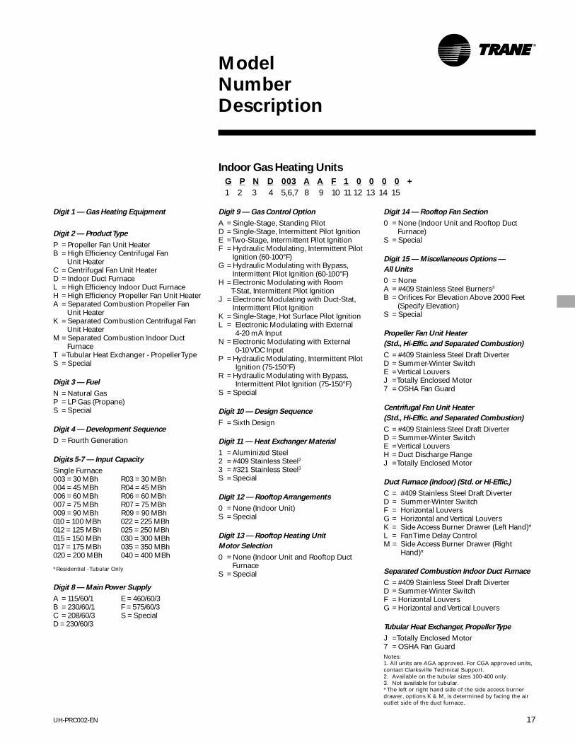
Digit 14 — Rooftop Fan Section
0 = None (Indoor Unit and Rooftop Duct Furnace)
S = Special
Digit 15 — Miscellaneous Options —
All Units
0 = NoneA = #409 Stainless Steel Burners3
B = Orifices For Elevation Above 2000 Feet (Specify Elevation)
S = Special
Propeller Fan Unit Heater
(Std., Hi-Effic. and Separated Combustion)
C = #409 Stainless Steel Draft DiverterD = Summer-Winter SwitchE = Vertical LouversJ = Totally Enclosed Motor7 = OSHA Fan Guard
Centrifugal Fan Unit Heater
(Std., Hi-Effic. and Separated Combustion)
C = #409 Stainless Steel Draft DiverterD = Summer-Winter SwitchE = Vertical LouversH = Duct Discharge FlangeJ = Totally Enclosed Motor
Duct Furnace (Indoor) (Std. or Hi-Effic.)
C = #409 Stainless Steel Draft DiverterD = Summer-Winter SwitchF = Horizontal LouversG = Horizontal and Vertical LouversK = Side Access Burner Drawer (Left Hand)*L = Fan Time Delay ControlM = Side Access Burner Drawer (Right
Hand)*
Separated Combustion Indoor Duct Furnace
C = #409 Stainless Steel Draft DiverterD = Summer-Winter SwitchF = Horizontal LouversG = Horizontal and Vertical Louvers
Tubular Heat Exchanger, Propeller Type
J = Totally Enclosed Motor7 = OSHA Fan Guard
ModelNumberDescription
Indoor Gas Heating Units
G P N D 003 A A F 1 0 0 0 0 +
1 2 3 4 5,6,7 8 9 10 11 12 13 14 15
Digit 1 — Gas Heating Equipment
Digit 2 — Product Type
P = Propeller Fan Unit HeaterB = High Efficiency Centrifugal Fan
Unit HeaterC = Centrifugal Fan Unit HeaterD = Indoor Duct FurnaceL = High Efficiency Indoor Duct FurnaceH = High Efficiency Propeller Fan Unit HeaterA = Separated Combustion Propeller Fan
Unit HeaterK = Separated Combustion Centrifugal Fan
Unit HeaterM = Separated Combustion Indoor Duct
FurnaceT = Tubular Heat Exchanger - Propeller TypeS = Special
Digit 3 — Fuel
N = Natural GasP = LP Gas (Propane)S = Special
Digit 4 — Development Sequence
D = Fourth Generation
Digits 5-7 — Input Capacity
Single Furnace003 = 30 MBh R03 = 30 MBh 004 = 45 MBh R04 = 45 MBh 006 = 60 MBh R06 = 60 MBh 007 = 75 MBh R07 = 75 MBh 009 = 90 MBh R09 = 90 MBh010 = 100 MBh 022 = 225 MBh 012 = 125 MBh 025 = 250 MBh 015 = 150 MBh 030 = 300 MBh 017 = 175 MBh 035 = 350 MBh020 = 200 MBh 040 = 400 MBh
*Residential - Tubular Only
Digit 8 — Main Power Supply
A = 115/60/1 E = 460/60/3B = 230/60/1 F = 575/60/3C = 208/60/3 S = SpecialD = 230/60/3
Notes:1. All units are AGA approved. For CGA approved units,contact Clarksville Technical Support.2. Available on the tubular sizes 100-400 only.3. Not available for tubular.*The left or right hand side of the side access burnerdrawer, options K & M, is determined by facing the airoutlet side of the duct furnace.
Digit 9 — Gas Control Option
A = Single-Stage, Standing PilotD = Single-Stage, Intermittent Pilot IgnitionE = Two-Stage, Intermittent Pilot IgnitionF = Hydraulic Modulating, Intermittent Pilot
Ignition (60-100°F)G = Hydraulic Modulating with Bypass,
Intermittent Pilot Ignition (60-100°F)H = Electronic Modulating with Room
T-Stat, Intermittent Pilot IgnitionJ = Electronic Modulating with Duct-Stat,
Intermittent Pilot IgnitionK = Single-Stage, Hot Surface Pilot IgnitionL = Electronic Modulating with External
4-20 mA InputN = Electronic Modulating with External
0-10 VDC InputP = Hydraulic Modulating, Intermittent Pilot
Ignition (75-150°F)R = Hydraulic Modulating with Bypass,
Intermittent Pilot Ignition (75-150°F)S = Special
Digit 10 — Design Sequence
F = Sixth Design
Digit 11 — Heat Exchanger Material
1 = Aluminized Steel2 = #409 Stainless Steel23 = #321 Stainless Steel3S = Special
Digit 12 — Rooftop Arrangements
0 = None (Indoor Unit)S = Special
Digit 13 — Rooftop Heating Unit
Motor Selection
0 = None (Indoor Unit and Rooftop Duct Furnace
S = Special

UH-PRC002-EN18
ModelNumberDescription
(Horizontal BlowerAssembly)
Digit 1-3 — Horizontal Blower Assembly
Digit 4 — Development Sequence
C = Third Generation
Digit 5-6 — Blower Size
15= Nominal 1500 cfm20= Nominal 2000 cfm30= Nominal 3000 cfm45= Nominal 4500 cfm
Digit 7 — Transition Size
(Specifies Duct Furnace Size)
0 = NoneA = 100 MBh F = 225 MBhB = 125 MBh G = 250 MBhC = 150 MBh H = 300 MBhD = 175 MBh J = 350 MBhE = 200 MBh K = 400 MBh
Horizontal Blower Assembly
HBA C 15 A A A C 0 +
1 2 3 4 5 6 7 8 9 10 11
Digit 8 — Main Power Supply
A = 115/60/1 D = 230/60/3B = 230/60/1 E = 460/60/3C = 208/60/3 S = Special
Digit 9 — Motor Horsepower
A = 1/3 hp E = 1½ hpB = ½ hp F = 2 hpC = ¾ hp S = SpecialD = 1 hp
Digit 10 — Design Sequence
C = Third Design
Digit 11 — Miscellaneous Options
0 = None1 = Insulation3 = Totally Enclosed MotorS = Special

19UH-PRC002-EN
GeneralData
Table GD-1 — Minimum Clearances
Duct Propeller & CentrifugalFurnace Fan U.H.
Sides 18” 18”Top 6” 6”Bottom 21”* 21”Flue 6” 6”*21” clearance is required for bottom access toburners and pilot. If a side pull-out burner drawer isordered (duct furnace only), bottom clearance can bereduced to six inches. Side clearance, however, mustbe increased such that it is adequate for burner drawerremoval. Reference Tables DW-10 and DW-11.
Table GD-2 – Standard Unit Heater Approximate Distance of Throw at Nominal Airflow
Distance FromFloor to Bottom Unit Size – Input MBh – (kW)
of Unit “H” 30 45 60 75 100 125 150 175 200 225 250 300 350 400ft./(m) (8.8) (13.2) (17.6) (22.0) (29.3) (36.6) (43.9) (51.2) (58.6) (65.9) (73.2) (87.8) (102.5) (117.1)
8 33 33 33 40 60 65 70 75 80 85 90 105 110 120(2.4) (10.1) (10.1) (10.1) (12.2) (18.3) (19.8) (21.3) (22.9) (24.4) (25.9) (27.4) (32.0) (33.5) (36.6)10 28 28 28 35 54 56 60 64 68 72 78 90 95 100
(3.0) (8.5) (8.5) (8.5) (10.7) (16.5) (17.1) (18.3) (19.5) (20.7) (21.9) (23.8) (27.4) (29.0) (30.5)12 NR NR NR NR 44 46 49 57 61 65 68 80 84 90
(3.7) (13.4) (14.0) (14.9) (17.4) (18.6) (19.8) (20.7) (24.4) (25.6) (27.4)15 NR NR NR NR NR NR 45 49 52 56 60 70 74 80
(4.6) (13.7) (14.9) (15.8) (17.1) (18.3) (21.3) (22.6) (24.4)20 NR NR NR NR NR NR NR NR 46 50 54 63 66 70
(6.1) (14.0) (15.2) (16.5) (19.2) (20.1) (21.3)
Standard Unit Heater Applications
30° Nozzle
NR = Not RecommendedNotes:1. All throw data figures are approximate.2. NR = not recommended at these mounting heights.3. Nozzles are not available on units below size 100 MBh.4. Nozzles are available for High Efficiency units. Specify High Efficiency when ordering due to difference in nozzleconfiguration.
Table GD-3 – 30 Degree Nozzle – Approximate Distance of Throw at Nominal Airflow
Distance FromFloor to Bottom Unit Size – Input MBh – (kW)
of Unit “H” 100 125 150 175 200 225 250 300 350 400ft./(m) (29.3) (36.6) (43.9) (51.2) (58.6) (65.9) (73.2) (87.8) (102.5) (117.1)
8 65 70 75 80 85 90 95 115 120 125(2.4) (19.8) (21.3) (22.9) (24.4) (25.9) (27.4) (29.0) (35.1) (36.6) (38.1)
10 57 60 64 68 72 78 86 99 105 110(3.0) (17.4) (18.3) (19.5) (20.7) (21.9) (23.8) (26.2) (30.2) (32.0) (33.5)
12 50 54 57 60 64 70 77 88 94 100(3.7) (15.2) (16.5) (17.4) (18.3) (19.5) (21.3) (23.5) (26.8) (28.7) (30.5)
15 NR 45 48 50 53 59 64 74 79 84(4.6) (13.7) (14.6) (15.2) (16.2) (18.0) (19.5) (22.6) (24.1) (25.6)
20 NR NR NR 44 47 53 58 66 71 75(6.1) (13.4) (14.3) (16.2) (17.7) (20.1) (21.6) (22.9)

UH-PRC002-EN20
60° Nozzle
90° Nozzle
“Y” Splitter
Table GD-4 – 60 Degree Nozzle – Approximate Distance of Throw at Nominal Airflow
Distance FromFloor to Bottom Unit Size – Input MBh – (kW)
of Unit “H” 100 125 150 175 200 225 250 300 350 400ft./(m) (29.3) (36.6) (43.9) (51.2) (58.6) (65.9) (73.2) (87.8) (102.5) (117.1)
8 75 80 85 90 95 100 110 125 130 138(2.4) (22.9) (24.4) (25.9) (27.4) (29.0) (30.5) (33.5) (38.1) (39.6) (42.1)
10 65 70 75 79 83 88 95 109 115 120(3.0) (19.8) (21.3) (22.9) (24.1) (25.3) (26.8) (29.0) (33.2) (35.1) (36.6)
12 60 64 68 72 76 80 84 100 103 108(3.7) (18.3) (19.8) (20.7) (21.9) (23.2) (24.4) (25.6) (30.5) (31.4) (32.9)
15 50 54 56 61 65 68 71 85 88 94(4.6) (15.2) (16.5) (17.1) (18.6) (19.8) (20.7) (21.6) (25.9) (26.8) (28.7)
20 NR 49 52 55 59 61 65 77 81 85(6.1) (14.9) (15.8) (16.8) (18.0) (18.6) (19.8) (23.5) (24.7) (25.9)
Table GD-5 – 90 Degree Nozzles – Approximate Floor Coverage at Nominal Airflow
Distance From Floor to Bottom of Unit “H” – ft./(m)Unit 10' 15' 20' 25' 30'Size (3.0) (4.6) (6.1) (7.6) (9.1)100 NR 30 x 25 NR NR NR
(9.1 x 7.6)125 NR 35 x 30 NR NR NR
(10.7 x 9.1)150 NR 40 x 35 NR NR NR
(12.2 x 10.7)175 NR 45 x 40 NR NR NR
(13.7 x 12.2)200 NR 50 x 40 40 x 35 NR NR
(15.2 x 12.2) (12.2 x 10.7)225 NR 55 x 40 48 x 35 NR NR
(16.8 x 12.2) (14.6 x 10.7)250 NR 60 x 45 56 x 40 50 x 35 NR
(18.3 x 13.7) (17.1 x 12.2) (15.2 x 10.7)300 NR 70 x 45 65 x 40 60 x 35 55 x 35
(21.3 x 13.7) (19.8 x 12.2) (18.3 x 10.7) (16.8 x 10.7)350 NR 80 x 50 70 x 45 65 x 40 60 x 35
(24.4 x 15.2) (21.3 x 13.7) (19.8 x 12.2) (18.3 x 10.7)400 NR 100 x 50 80 x 45 75 x 40 65 x 40
(30.5 x 15.2) (24.4 x 13.7) (22.9 x 12.2) (19.8 x 12.2)
Table GD-6 – “Y” Splitters – Approximate Distance of Throw at Nominal Airflow
Distance FromFloor to Bottom Unit Size – Input MBh – (kW)
of Unit “H” 100 125 150 175 200 225 250 300 350 400ft./(m) (29.3) (36.6) (43.9) (51.2) (58.6) (65.9) (73.2) (87.8) (102.5) (117.1)
8 47 51 60 65 70 72 80 95 100 103(2.4) (14.3) (15.5) (18.3) (19.8) (21.3) (21.9) (24.4) (29.0) (30.5) (31.4)
10 41 44 52 56 61 63 69 82 87 92(3.0) (12.5) (13.4) (15.8) (17.1) (18.6) (19.2) (21.0) (25.0) (26.5) (28.0)
12 37 40 47 51 55 57 63 75 79 82(3.7) (11.3) (12.2) (14.3) (15.5) (16.8) (17.4) (19.2) (22.9) (24.1) (25.0)
NR = Not RecommendedNotes:1. All throw data figures are approximate.2. NR = not recommended at these mounting heights.3. Nozzles are not available on units below size 100 MBh.4. Nozzles are available for High Efficiency units. Specify High Efficiency when ordering due to difference in nozzleconfiguration.
GeneralData

21UH-PRC002-EN
Table PD-1 – High Efficiency Propeller Fan Gas Unit Heater Performance Data
Model GHND/ GHND/ GHND/ GHND/ GHND/ GHND/ GHND/ GHND/ GHND/ GHND/ GHND/ GHND/ GHND/ GHND/GHPD GHPD GHPD GHPD GHPD GHPD GHPD GHPD GHPD GHPD GHPD GHPD GHPD GHPD
Unit Size 003 004 006 007 010 012 015 017 020 022 025 030 035 040Input MBh 30 45 60 75 100 125 150 175 200 225 250 300 350 400 (kW) 8.8 13.2 17.6 22.0 29.3 36.6 43.9 51.2 58.6 65.9 73.2 87.8 102.5 117.1Output MBh 24 36 42 60 80 100 120 140 160 120 200 240 280 320 (kW) 7.0 10.5 14.1 17.6 23.4 29.3 35.1 41.0 46.9 52.7 58.6 70.3 82.0 93.7Thermal Efficiency 80% 80% 80% 80% 80% 80% 80% 80% 80% 80% 80% 80% 80% 80%Free Air Delivery cfm 750 800 1,050 1,100 1,480 1,650 2,200 2,530 2,640 2,700 3,100 4,400 5,000 5,300 (cu. m/s) 0.354 0.378 0.496 0.519 0.699 0.779 1.038 1.194 1.246 1.274 1.463 2.077 2.360 2.502Air Temperature Rise °F 30 42 42 50 50 56 50 51 56 61 60 50 52 56 °F 17 23 23 28 28 31 28 28 31 34 33 28 29 31Outlet Velocity fpm 680 720 610 640 775 910 1,045 1,070 1,010 950 980 1,100 1,150 1,050 (m/s) 3.45 3.66 3.10 3.25 3.94 4.62 5.31 5.44 5.13 4.83 4.98 5.59 5.84 5.33Full Load Amps at 115V 4.5 4.5 4.5 4.5 5.8 6 7.2 8.2 8.2 8.2 8.2 11.2 13.2 13.2Motor Data: hp 1/30 1/30 1/30 1/30 1/20 1/10 1/4 1/3 1/3 1/3 1/3 (2)1/4 (2)1/3 (2)1/3 (kW) 0.025 0.025 0.025 0.025 0.037 0.075 0.186 0.249 0.249 0.249 0.249(2) 0.186 (2) 0.249 (2) 0.249 Type SP SP SP SP SP SP PSC PSC PSC PSC PSC PSC PSC PSC rpm 1,050 1,050 1,050 1,050 1,050 1,050 1,140 1,140 1,140 1,140 1,140 1,140 1,140 1,140 Amps @ 115V 1.3 1.3 1.3 1.3 2.6 2.8 4.0 4.5 4.5 4.5 4.5 8.0 9.0 9.0Notes:1. Ratings are shown for elevations up to 2,000 feet above sea level. Above 2,000 feet, input must be derated 4 percent for each 1,000 feet above sea level.2. Standard 115/60/1 open drip-proof motor.3. Thermal efficiency for the 003 and 004 units are based on stack in horizontal position.4. The flue vent fan motors used on all high efficiency units are 115/60/1; 1/20 hp and 1.5 amps.
Table PD-2 – High Efficiency Centrifugal Fan Unit Heater Performance Data
Model GBND/ GBND/ GBND/ GBND/ GBND/ GBND/ GBND/ GBND/ GBND/ GBND/GBPD GBPD GBPD GBPD GBPD GBPD GBPD GBPD GBPD GBPD
Unit Size 010 012 015 017 020 022 025 030 035 040Input MBh 100 125 150 175 200 225 250 300 350 400 (kW) 29.3 36.6 43.9 51.2 58.6 65.9 73.2 87.8 102.5 117.1Output MBh 80 100 120 140 160 180 200 240 280 320 (kW) 23.4 29.3 35.1 41.0 46.9 52.7 58.6 70.3 82.0 93.7Thermal Efficiency 80% 80% 80% 80% 80% 80% 80% 80% 80% 80%Free Air Delivery cfm 1,200 1,575 1,975 2,300 2,400 2,600 2,850 3,950 4,600 4,800 (cu. m/s) 0.566 0.743 0.932 1.086 1.133 1.227 1.345 1.864 2.171 2.266Air Temperature Rise °F 62 59 56 56 62 64 65 56 56 62 °C 34 33 31 31 34 36 36 31 31 34Outlet Velocity fpm 880 950 1,030 1,045 965 935 930 1,080 1,090 1,000 (m/s) 4.47 4.83 5.23 5.31 4.90 4.72 4.72 5.49 5.54 5.08Full Load Amps at 115V 8.3 9.8 10.6 10.6 15.2 15.2 15.2 15.2 18.6 18.6Motor Data : hp ¼ 1/3 ½ ½ ¾ ¾ ¾ ¾ 1 1 (kW) 0.19 0.25 0.37 0.37 0.56 0.56 0.56 0.56 0.75 0.75 Type SHP SHP SHP SHP SHP SHP SHP SHP CS CS rpm 1,725 1,725 1,725 1,725 1,725 1,725 1,725 1,725 1,725 1,725 Amps @ 115V 5.1 6.6 7.4 7.4 12.0 12.0 12.0 12.0 15.4 15.4Notes:1. Ratings are shown for elevations up to 2,000 feet above sea level. Above 2,000 feet, input must be derated 4 percent for each 1,000 feet above sea level.2. Standard motors are 115V 60 Hz, single phase open drip-proof.3. The flue vent fan motors used on all high efficiency units are 115/60/1; 1/20 hp and 1.5 amps. All other voltages will require an additional transformer.4. SPH= Split Phase; CS = Capacitor Start5. 0.2” maximum external static pressure.
PerformanceData
Table PAF-1 — Altitude Correction Factors
Correction Factors For High Altitude InstallationsAltitude Above Sea Level (FT) 0 2,000 3,000 4,000 5,000 6,000 7,000Gas Heating Capacity 1.00 0.92 0.88 0.84 0.80 0.76 0.72Fan rpm 1.00 1.04 1.06 1.09 1.12 1.15 1.19Fan bhp 1.00 1.07 1.12 1.18 1.25 1.33 1.41Notes:1. For high altitude installations above 2,000’, reduce ratings 4% for each 1,000’ above sea level.2. Multiply standard unit by correction factor to get actual input and required rpm and hp.

UH-PRC002-EN22
PerformanceData
Table PD-3 – Separated Combustion Propeller Fan Gas Unit Heater Performance Data
Model GAND/ GAND/ GAND/ GAND/ GAND/ GAND/ GAND/ GAND/ GAND/ GAND/GAPD GAPD GAPD GAPD GAPD GAPD GAPD GAPD GAPD GAPD
Unit Size 010 012 015 017 020 022 025 030 035 040Input MBh 100 125 150 175 200 225 250 300 350 400 (kW) 29.3 36.6 43.9 51.2 58.6 65.9 73.2 87.8 102.5 117.1Output MBh 80 100 120 140 160 180 200 240 280 320 (kW) 23.4 29.3 35.1 41.0 46.9 52.7 58.6 70.3 82.0 93.7Thermal Efficiency 80% 80% 80% 80% 80% 80% 80% 80% 80% 80%Free Air Delivery cfm 1480 1650 2200 2530 2640 2700 3100 4400 5000 5300 (cu. m/s) 0.699 0.779 1.038 1.194 1.246 1.274 1.463 2.077 2.360 2.502Air Temperature Rise °F 50 56 50 51 56 61 60 50 52 56 °C 28 31 28 28 31 34 33 28 29 31Outlet Velocity fpm 775 910 1045 1070 1000 950 980 1100 1150 1050 (m/s) 3.9 4.6 5.3 5.4 5.1 4.8 5.0 5.6 5.8 5.3Full Load Amps at 115V 5.8 6.0 7.2 7.8 7.8 7.8 8.8 11.2 12.2 12.2Motor Data: hp 1/20 1/10 1/4 1/3 1/3 1/3 1/2 (2) 1/4 (2) 1/3 (2) 1/3 (kW) 0.037 0.075 0.186 0.249 0.249 0.249 0.373 (2) 0.186 (2) 0.249 (2) 0.249 Type SP SP PSC PSC PSC PSC PSC PSC PSC PSC rpm 1,050 1,050 1,140 1,140 1,140 1,140 1,140 1,140 1,140 1,140 Amps @ 115V 2.6 2.8 4.0 4.5 4.5 4.5 5.5 8.0 9.0 9.0Notes:1. Ratings are shown for elevations up to 2,000 feet above sea level. Above 2,000 feet, input must be derated 4 percent for each 1,000 feet above sea level.2. Standard motor is 115/60/1 open drip-proof.3. SP = Shaded Pole; PSC = Permanent Split Capacitor.
Table PD-4 – Separated Combustion Centrifugal Fan Gas Unit Heater Performance Data
Model GKND/ GKND/ GKND/ GKND/ GKND/ GKND/ GKND/ GKND/ GKND/ GKND/GKPD GKPD GKPD GKPD GKPD GKPD GKPD GKPD GKPD GKPD
Unit Size 010 012 015 017 020 022 025 030 035 040Input MBh 100 125 150 175 200 225 250 300 350 400 (kW) 29.3 36.6 43.9 51.2 58.6 65.9 73.2 87.8 102.5 117.1Output MBh 80 100 120 140 160 180 200 240 280 320 (kW) 23.4 29.3 35.1 41.0 46.9 52.7 58.6 70.3 82.0 93.7Thermal Efficiency 80% 80% 80% 80% 80% 80% 80% 80% 80% 80%Free Air Delivery cfm 1,200 1,575 1,975 2,300 2,400 2,600 2,850 3.950 4,600 4,800 (cu. m/s) 0.566 0.743 0.932 1.086 1.133 1.227 1.345 1.864 2.171 2.266Air Temperature Rise °F 62 59 56 56 62 64 65 56 56 62 °C 34 33 31 31 34 36 36 31 31 34Outlet Velocity fpm 880 950 1030 1045 965 935 930 1080 1090 1000 (m/s) 4.47 4.83 5.23 5.31 4.90 4.75 4.72 5.49 5.54 5.08Full Load Amps at 115V 8.3 9.8 10.6 10.6 15.2 15.2 15.2 15.2 18.6 18.6Motor Data: hp ¼ 1/3 ½ ½ ¾ ¾ ¾ ¾ 1 1 (kW) 0.19 0.25 0.37 0.37 0.56 0.56 0.56 0.56 0.75 0.75 Type SPH SPH SPH SPH SPH SPH SPH SPH CS CS rpm 1725 1725 1725 1725 1725 1725 1725 1725 1725 1725 Amps @ 115V 5.1 6.6 7.4 7.4 12.0 12.0 12.0 12.0 15.4 15.4Notes:1. Ratings are shown for elevations up to 2,000 feet above sea level. Above 2,000 feet, input must be derated 4 percent for each 1,000 feet above sea level.2. Standard motor is 115/60/1 open drip-proof.3. SPH = Split Phase; CS = Capacitor Start.

23UH-PRC002-EN
PerformanceData
Table PD-5 – Propeller Fan Gas Unit Heater Performance Data
Model GPND/ GPND/ GPND/ GPND/ GPND/ GPND/ GPND/ GPND/ GPND/ GPND/ GPND/ GPND/ GPND/ GPND/GPPD GPPD GPPD GPPD GPPD GPPD GPPD GPPD GPPD GPPD GPPD GPPD GPPD GPPD
Unit Size 003 004 006 007 010 012 015 017 020 022 025 030 035 040Input MBh 30 45 60 75 100 125 150 175 200 225 250 300 350 400 (kW) 8.8 13.2 17.6 22.0 29.3 36.6 43.9 51.2 58.6 65.9 73.2 87.8 102.5 117.1Output MBh 24.3 36.5 48.6 60.8 80 100 120 140 160 180 200 240 280 320 (kW) 7.1 10.7 14.2 17.8 23.4 29.3 35.1 41.0 46.9 52.7 58.6 70.3 82.0 93.7Thermal Efficiency 81% 81% 81% 81% 80% 80% 80% 80% 80% 80% 80% 80% 80% 80%Free Air Delivery cfm 700 800 1050 1100 1480 1650 2200 2530 2640 2700 3100 4400 5000 5300 (cu. m/s) 0.330 0.378 0.496 0.519 0.699 0.779 1.038 1.194 1.246 1.274 1.463 2.077 2.360 2.502Air Temperature Rise °F 30 42 42 50 50 56 50 51 56 61 60 50 52 56 °C 17 23 23 28 28 31 28 28 31 34 33 28 29 31Outlet Velocity fpm 700 750 640 672 950 900 1045 1070 1000 950 980 1100 1150 1050 (m/s) 3.6 3.8 3.3 3.4 4.8 4.6 5.3 5.4 5.1 4.8 5.0 5.6 5.8 5.3Full Load Amps at 115V 2.1 2.1 2.1 2.1 3.4 3.6 4.8 5.8 5.8 5.8 5.8 8.8 10.8 10.8Motor Data: hp 1/30 1/30 1/30 1/30 1/20 1/10 1/4 1/3 1/3 1/3 1/3 (2) 1/4 (2) 1/3 (2) 1/3 (kW) 0.025 0.025 0.025 0.025 0.037 0.075 0.186 0.249 0.249 0.249 0.249(2) 0.186 (2) 0.249 (2) 0.249 Type SP SP SP SP SP SP PSC PSC PSC PSC PSC PSC PSC PSC rpm 1,050 1,050 1,050 1,050 1,050 1,050 1,140 1,140 1,140 1,140 1,140 1,140 1,140 1,140 Amps @ 115V 1.3 1.3 1.3 1.3 2.6 2.8 4.0 4.5 4.5 4.5 4.5 8.0 9.0 9.0Notes:1. Ratings are shown for elevations up to 2,000 feet above sea level. Above 2,000 feet, input must be derated 4 percent for each 1,000 feet above sea level.2. Standard motor is 115/60/1 open drip-proof.3. SP = Shaded Pole; PSC = Permanent Split Capacitor4. Unit amps are based on standing pilot units.
Table PD-6 – Tubular Heat Exchanger Performance Data
Model GTND/ GTND/ GTND/ GTND/ GTND/ GTND/ GTND/ GTND/ GTND/ GTND/ GTND/ GTND/ GTND/ GTND/GTPD GTPD GTPD GTPD GTPD GTPD GTPD GTPD GTPD GTPD GTPD GTPD GTPD GTPD
Unit Size 003 004 006 007 009 010 012 015 017 020 025 030 035 040Input MBh 30 45 60 75 90 100 125 150 175 200 250 300 350 400 (kW) 8.8 13.2 17.6 22.0 26.4 29.3 36.6 43.9 51.2 58.6 73.2 87.8 102.5 117.1Output MBh 24.3 36.5 48.6 60.8 72.9 81.0 101.3 121.5 141.8 162.0 202.5 243.0 283.5 324.0 (kW) 7.1 10.7 14.2 17.8 21.4 23.7 29.6 35.6 41.5 47.5 59.3 71.2 83.0 95.0Thermal Efficiency 81 81 81 81 81 81 81 81 81 81 81 81 81 81Free Air Delivery cfm 500 750 1,000 1,250 1,500 1,600 2,200 2,400 2,850 3,200 3,450 5,000 5,600 5,800 (cu m/s) 0.236 0.355 0.473 0.591 0.710 0.756 1.039 1.133 1.346 1.511 1.629 2.361 2.644 2.738Air Temperature Rise °F 45 45 45 45 45 47 42 47 46 47 54 45 47 51 °C 25 25 25 25 25 26 23 26 26 26 30 25 26 28Full Load Amps at 120V 4.9 4.9 5.6 5.6 5.6 6.6 8.0 7.8 8.3 8.3 8.3 12.5 12.5 12.5Motor Data hp 1/20 1/20 1/20 1/20 1/20 1/10 1/4 1/4 1/3 1/3 1/3 1/4 1/3 1/3 (kW) 0.37 0.37 0.37 0.37 0.37 0.75 0.19 0.19 0.25 0.25 0.25 0.19 0.25 0.25 Type SP SP SP SP SP SP PSC PSC PSC PSC PSC PSC PSC PSC rpm 1,650 1,650 1,050 1,050 1,050 1,050 1,140 1,140 1,140 1,140 1,140 1,140 1,140 1,140 Amps at 115V 1.9 1.9 2.6 2.6 2.6 2.8 4.0 4.0 4.5 4.5 4.5 8.0 9.0 9.0Notes:1. Ratings are shown for elevations up to 2,000 feet above sea level. Above 2,000 feet, input must be derated 4 percent for each 1,000 feet above sea level.2. CS = Capacitor Start; SPH = Split Capacitor3. Standard motors are 115/60/1 open drip-proof.4. 0.2 maximum external static pressure.5. Unit amps are based on hot surface pilot ignition.
UH-PRC002-EN24
PerformanceData
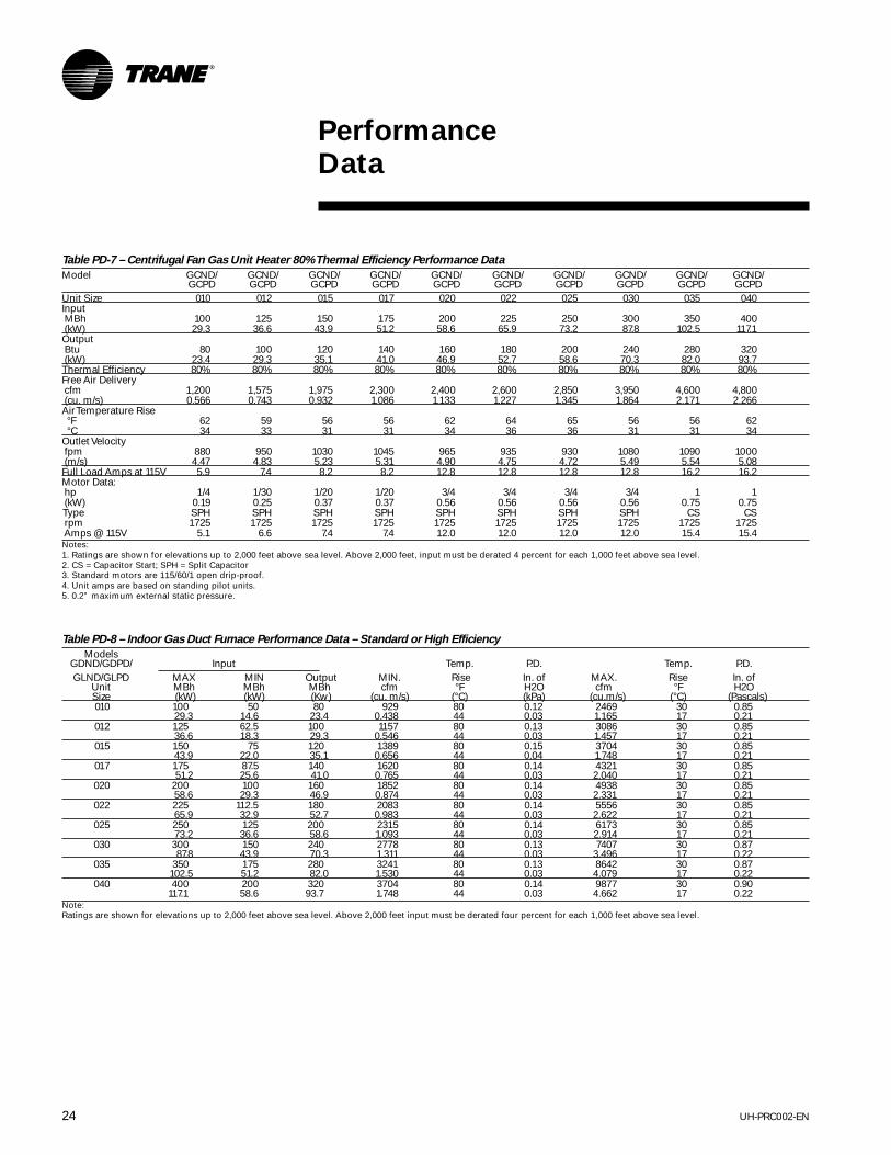
Table PD-7 – Centrifugal Fan Gas Unit Heater 80% Thermal Efficiency Performance Data
Model GCND/ GCND/ GCND/ GCND/ GCND/ GCND/ GCND/ GCND/ GCND/ GCND/GCPD GCPD GCPD GCPD GCPD GCPD GCPD GCPD GCPD GCPD
Unit Size 010 012 015 017 020 022 025 030 035 040Input MBh 100 125 150 175 200 225 250 300 350 400 (kW) 29.3 36.6 43.9 51.2 58.6 65.9 73.2 87.8 102.5 117.1Output Btu 80 100 120 140 160 180 200 240 280 320 (kW) 23.4 29.3 35.1 41.0 46.9 52.7 58.6 70.3 82.0 93.7Thermal Efficiency 80% 80% 80% 80% 80% 80% 80% 80% 80% 80%Free Air Delivery cfm 1,200 1,575 1,975 2,300 2,400 2,600 2,850 3,950 4,600 4,800 (cu. m/s) 0.566 0.743 0.932 1.086 1.133 1.227 1.345 1.864 2.171 2.266Air Temperature Rise °F 62 59 56 56 62 64 65 56 56 62 °C 34 33 31 31 34 36 36 31 31 34Outlet Velocity fpm 880 950 1030 1045 965 935 930 1080 1090 1000 (m/s) 4.47 4.83 5.23 5.31 4.90 4.75 4.72 5.49 5.54 5.08Full Load Amps at 115V 5.9 7.4 8.2 8.2 12.8 12.8 12.8 12.8 16.2 16.2Motor Data: hp 1/4 1/30 1/20 1/20 3/4 3/4 3/4 3/4 1 1 (kW) 0.19 0.25 0.37 0.37 0.56 0.56 0.56 0.56 0.75 0.75 Type SPH SPH SPH SPH SPH SPH SPH SPH CS CS rpm 1725 1725 1725 1725 1725 1725 1725 1725 1725 1725 Amps @ 115V 5.1 6.6 7.4 7.4 12.0 12.0 12.0 12.0 15.4 15.4Notes:1. Ratings are shown for elevations up to 2,000 feet above sea level. Above 2,000 feet, input must be derated 4 percent for each 1,000 feet above sea level.2. CS = Capacitor Start; SPH = Split Capacitor3. Standard motors are 115/60/1 open drip-proof.4. Unit amps are based on standing pilot units.5. 0.2” maximum external static pressure.
Table PD-8 – Indoor Gas Duct Furnace Performance Data – Standard or High Efficiency
ModelsGDND/GDPD/ Input Temp. P.D. Temp. P.D.GLND/GLPD MAX MIN Output MIN. Rise In. of MAX. Rise In. of
Unit MBh MBh MBh cfm °F H2O cfm °F H2OSize (kW) (kW) (Kw) (cu. m/s) (°C) (kPa) (cu.m/s) (°C) (Pascals)010 100 50 80 929 80 0.12 2469 30 0.85
29.3 14.6 23.4 0.438 44 0.03 1.165 17 0.21012 125 62.5 100 1157 80 0.13 3086 30 0.85
36.6 18.3 29.3 0.546 44 0.03 1.457 17 0.21015 150 75 120 1389 80 0.15 3704 30 0.85
43.9 22.0 35.1 0.656 44 0.04 1.748 17 0.21017 175 87.5 140 1620 80 0.14 4321 30 0.85
51.2 25.6 41.0 0.765 44 0.03 2.040 17 0.21020 200 100 160 1852 80 0.14 4938 30 0.85
58.6 29.3 46.9 0.874 44 0.03 2.331 17 0.21022 225 112.5 180 2083 80 0.14 5556 30 0.85
65.9 32.9 52.7 0.983 44 0.03 2.622 17 0.21025 250 125 200 2315 80 0.14 6173 30 0.85
73.2 36.6 58.6 1.093 44 0.03 2.914 17 0.21030 300 150 240 2778 80 0.13 7407 30 0.87
87.8 43.9 70.3 1.311 44 0.03 3.496 17 0.22035 350 175 280 3241 80 0.13 8642 30 0.87
102.5 51.2 82.0 1.530 44 0.03 4.079 17 0.22040 400 200 320 3704 80 0.14 9877 30 0.90
117.1 58.6 93.7 1.748 44 0.03 4.662 17 0.22Note:Ratings are shown for elevations up to 2,000 feet above sea level. Above 2,000 feet input must be derated four percent for each 1,000 feet above sea level.

25UH-PRC002-EN
PerformanceData
Table PD-9 – Horizontal Blower Assembly Performance Data
External Static PressureWaterIn. 0.2 0.3 0.4 0.5 0.6 0.7 0.8 0.9Kpa 0.05 0.07 0.10 0.12 0.15 0.17 0.20 0.22
Nominal Blower cfm rpm hp rpm hp rpm hp rpm hp rpm hp rpm hp rpm hP rpm hpModels cfm Size cu.m/s kW kW kW kW kW kW kW kW
1,250 525 1/3 650 1/3 680 1/3 760 1/3 780 1/3 840 1/3 — Not Applicable —0.590 0.25 0.25 0.25 0.25 0.25 0.25
HBAC-15 1,500 10” 1,500 600 1/3 680 1/3 715 1/3 790 1/3 810 ½ 860 ½ 895 ½ 970 ½0.708 0.25 0.25 0.25 0.25 0.37 0.37 0.37 0.371,750 650 1/3 710 1/3 750 ½ 805 ½ 850 ½ 890 ½ 940 ¾ 990 ¾0.826 0.25 0.25 0.37 0.37 0.37 0.37 0.56 0.562,000 700 ½ 760 ½ 800 ½ 850 ½ 890 ½ 925 ¾ 980 ¾ 1,010 ¾0.944 0.37 0.37 0.37 0.37 0.37 0.56 0.56 0.561,500 425 1/3 500 1/3 550 1/3 630 1/3 - - - - - - - -0.708 0.25 0.25 0.25 0.251,750 450 1/3 515 1/3 560 1/3 635 ½ 680 ½ 725 ½ - - - -0.826 0.25 0.25 0.25 0.37 0.37 0.372,000 475 1/3 530 1/3 590 ½ 640 ½ 690 ½ 740 ½ 785 ½ 810 ¾0.944 0.25 0.25 0.37 0.37 0.37 0.37 0.37 0.56
HBAC-20 2,000 12” 2,250 515 ½ 560 ½ 610 ½ 650 ½ 700 ¾ 750 ¾ 790 ¾ 815 ¾1.062 0.37 0.37 0.37 0.37 0.56 0.56 0.56 0.562,500 540 ½ 590 ½ 625 ½ 670 ½ 710 ¾ 760 ¾ 795 ¾ 820 ¾1.180 0.37 0.37 0.37 0.37 0.56 0.56 0.56 0.562,750 575 ½ 615 ½ 650 ¾ 690 ¾ 730 ¾ 780 ¾ 800 ¾ 830 11.298 0.37 0.37 0.56 0.56 0.56 0.56 0.56 0.751,750 450 1/3 510 1/3 560 1/3 630 1/3 675 ½ 720 ½ - - - -0.826 0.25 0.25 0.25 0.25 0.37 0.372,000 475 1/3 525 1/3 590 ½ 635 ½ 680 ½ 735 ½ 785 ½ 810 ¾0.944 0.25 0.25 0.37 0.37 0.37 0.37 0.37 0.562,250 500 ½ 550 ½ 600 ½ 645 ½ 685 ½ 740 ¾ 785 ¾ 810 ¾1.062 0.37 0.37 0.37 0.37 0.37 0.56 0.56 0.56
HBAC-30 3,000 12” 2,500 525 ½ 580 ½ 615 ½ 665 ½ 700 ¾ 750 ¾ 790 ¾ 815 ¾1.180 0.37 0.37 0.37 0.37 0.56 0.56 0.56 0.562,750 560 ½ 605 ½ 640 ¾ 685 ¾ 715 ¾ 775 ¾ 805 ¾ 825 11.298 0.37 0.37 0.56 0.56 0.56 0.56 0.56 0.753,000 610 ½ 640 ¾ 660 ¾ 710 ¾ 750 1 790 1 815 1 845 11.416 0.37 0.56 0.56 0.56 0.75 0.75 0.75 0.753,250 630 ¾ 675 ¾ 700 1 735 1 750 1 790 1 830 1 860 11.534 0.56 0.56 0.75 0.75 0.75 0.75 0.75 0.753,500 675 ¾ 700 1 725 1 775 1 800 1 840 1½ 875 1½ 890 1½1.652 0.56 0.75 0.75 0.75 0.75 1.12 1.12 1.122,750 400 ¾ 450 ¾ 510 ¾ - - - - - - - - - -1.298 0.56 0.56 0.563,000 425 ¾ 475 ¾ 550 ¾ 600 ¾ 650 ¾ - - - - - -1.416 0.56 0.56 0.56 0.56 0.563,500 430 ¾ 480 ¾ 560 ¾ 610 ¾ 660 ¾ 700 1 730 1 - -1.652 0.56 0.56 0.56 0.56 0.56 0.75 0.754,000 450 ¾ 500 ¾ 565 ¾ 615 ¾ 670 1 710 1 740 1 790 11.888 0.56 0.56 0.56 0.56 0.75 0.75 0.75 0.754,500 475 ¾ 525 ¾ 575 ¾ 620 1 680 1 715 1 750 1 800 1½2.124 0.56 0.56 0.56 0.75 0.75 0.75 0.75 1.125,000 500 ¾ 540 ¾ 600 1 630 1 690 1 720 1½ 760 1½ 810 1½2.360 0.56 0.56 0.75 0.75 0.75 1.12 1.12 1.12
HBAC-45 4,500 12” 5,500 530 1 575 1 615 1 650 1½ 700 1½ 700 1½ 730 1½ 820 1½2.596 0.75 0.75 0.75 1.12 1.12 1.12 1.12 1.126,000 575 1½ 615 1½ 660 1½ 690 1½ 715 1½ 760 2 800 2 830 22.832 1.12 1.12 1.12 1.12 1.12 1.49 1.49 1.496,500 610 1½ 660 2 710 2 750 2 800 2 840 2 890 3 930 33.068 1.12 1.49 1.49 1.49 1.49 1.49 2.24 2.247,000 720 1½ 790 2 830 2 860 2 910 3 940 3 960 3 NA3.304 1.12 1.49 1.49 1.49 2.24 2.24 2.247,500 800 2 860 2 900 3 930 3 960 3 NA NA NA3.540 1.49 1.49 2.24 2.24 2.248,000 860 2 930 3 960 3 NA NA NA NA NA3.776 1.49 2.24 2.24
*External Static Pressure in inches of water. Add pressure drop of indoor duct furnace, if used, to pressure drop of ductwork, to determine total external static pressure.HBAC units are for use with specific duct furnace sizes. Reference Table DW-13.

UH-PRC002-EN26
PerformanceData
Table PD-10 – Separated Combustion Indoor Gas Duct Furnace
Input Output(Max) (Min) Min. Temp. Rise P.D. Max. Temp. Rise P.D.
Models MBh MBh MBh cfm °F In. of H20 cfm °F in. of H20GMND/GMPD (kW) (kW) (kW) (cu. m/s) (°C) (kPa) (cu.m/s) (°C) (Pascals)
010 100 50 80 822 90 0.10 3700 20 2.03(29.3) (14.6) (23.4) (0.388) (50) (0.02) (1.746) (11) (0.51)
012 125 62.5 100 1028 90 0.09 4625 20 1.92(36.6) (18.3) (29.3) (0.485) (50) (0.02) (2.183) (11) (0.48)
015 150 75 120 1233 90 0.09 5550 20 1.81(43.9) (22.0) (35.1) (0.582) (50) (0.02) (2.620) (11) (0.45)
017 175 87.5 140 1439 90 0.09 6475 20 1.86(51.2) (25.6) (41.0) (0.679) (50) (0.02) (3.056) (11) (0.46)
020 200 100 160 1645 90 0.09 7401 20 1.90(58.6) (29.3) (46.9) (0.776) (50) (0.02) (3.493) (11) (0.47)
022 225 112.5 180 1850 90 0.09 8326 20 1.93(65.9) (32.9) (52.7) (0.873) (50) (0.02) (3.930) (11) (0.48)
025 250 125 200 2056 90 0.09 9251 20 1.96(73.2) (36.6) (58.6) (0.970) (50) (0.02) (4.366) (11) (0.49)
030 300 150 240 2467 90 0.10 11101 20 2.00(87.8) (43.9) (70.3) (1.164) (50) (0.02) (5.240) (11) (0.50)
035 350 175 280 2878 90 0.10 12951 20 2.02(102.5) (51.2) (82.0) (1.358) (50) (0.02) (6.113) (11) (0.50)
040 400 200 320 3289 90 0.10 14801 20 2.05(117.1) (58.6) (93.7) (1.552) (50) (0.02) (6.986) (11) (0.51)
Note:Ratings are shown for elevations up to 2,000 feet (610m) above sea level. Above 2,000 feet (610m) input must be derated 4% for each 1,000 feet (305m) above sea level. When unitsare installed in Canada, any reference to derations at altitudes in excess of 2,000 feet (610m) are to be ignored. At altitudes of 2,000 to 4,500 (610 to 1372m), the units must beorificed to 90% of the normal altitude rating, and be so marked in accordance with the CGA certification.
Chart PD-1 – Performance Data Curves for all Duct Furnaces

27UH-PRC002-EN
Controls
Pilot Control
Standing pilot is standard on indoor ductfurnaces, propeller fan unit heaters andcentrifugal fan unit heaters. Highefficiency units (centrifugal, propeller andduct furnaces) ship as standard withintermittent pilot ignition. The separatedcombustion propeller and centrifugal fanunit heaters also ship as standard withintermittent pilot ignition.
Intermittent pilot ignition contains asolid-state ignition control system thatignites the pilot by spark for each cycle ofoperation. When the pilot flame isproven, the main burner valve opens toallow gas flow to the burners. Both thepilot and burners are extinguishedduring the off cycle.
Intermittent pilot ignition is ideal forlimited access installations wheremanual lighting of the pilot may bedifficult. Nuisance pilot outages on unitsmounted in areas subject to occasionalsevere drafts can also be eliminated.Energy savings will be realized using thissystem as the pilot is extinguishedduring the off cycle. Intermittent pilotignition should be considered on unitsthat have long shutoff periods.(Required on shipments to California.)
Fan Control
The supply fan motor is activated directlythrough the fan time delay relay onindoor units provided with single-phasemotors up to one hp. Contactors orstarters are required on all other unitswith single-phase motors 1½-hp andabove, and with all three-phase motors.On indoor units, contactors and starters,where required, are provided. (See tablebelow.)
Gas Controls
Single-Stage Control
Indoor gas heating units are providedwith an automatic single-stage gas valveas standard. This valve is an on/off typecontrol, typically activated by a lowvoltage single-stage thermostat.
Two-Stage Control
Indoor units with optional two-stagecontrol are provided with a two-stagegas valve capable of firing at 100 percentand 50 percent of rated input. Ignition isat low fire (50 percent of the unit’s ratedinput) and the unit is typically controlledby a low voltage two-stage thermostat.
Hydraulic Modulating Control
Units with optional hydraulic modulatingcontrol are provided with a modulatinggas valve capable of firing from 50percent to 100 percent of rated input.Ignition is at low fire (50 percent ofinput). The hydraulic modulating valve iscontrolled by a sensing bulb located inthe discharge airstream whichmodulates the gas input from 50 percentto 100 percent of rated input. The unit isalso provided with an automatic electricvalve in series with the hydraulicmodulating valve, which typically cyclesthe unit in response to a low voltagesingle-stage thermostat. Units that donot utilize a thermostat will operate as astanding pilot unit. The ignitor will lightthe pilot. The pilot will remain on untilpower is disconnected from the units.
Voltage ½ hp ¾hp 1hp 1½hp 2hp 3hp 5hp 7½hp 10hp115/60/1 1 1 1 2 2 N/A N/A N/A N/A230/60/1 1 1 1 2 2 N/A N/A N/A N/A208/60/3 2 2 2 2 2 2 2 4 4230/60/3 2 2 2 2 2 2 2 4 4460/60/3 3 3 3 3 3 3 3 5 5Notes:1. Contactors not required or provided on units with single phase motors up to one hp.2. Provided with contactor with line voltage holding coil on all 11/2 hp and above single-phase motors and on all 208230V three-phase motors up to five hp.3. Provided with contactor with low (24V) holding coil on all 460V three-phase motors up to five hp.4. Provided with size 2 starter on all units with 71/2 and 10 hp 208/230V three-phase motors.5. Provided with size 1 starter on all units with 71/2 and 10 hp 460V three-phase motors.
Hydraulic Modulating Control withBypass
An additional electric valve is provided inparallel with the hydraulic modulatingvalve. The electric valve bypasses the gasflow around the hydraulic modulatingvalve, allowing full fire and overridingthe modulating valve’s sensing bulbcontrol. The electric valve is activated bya low voltage single-stage thermostat.(Thermostat not included)(N/A on 30-75 MBh units)
Electronic Modulating Control
This optional control is available for usewith natural gas units only. Units withelectronic modulating control areprovided with an electronic modulatingvalve capable of firing from 100 percentto 50 percent of rated input. Ignition is atfull fire (100 percent of unit’s rated input).The electronic modulating valve iscontrolled by a room thermostat or aduct thermostat with remote setpointadjustment which modulates the gasinput from 100 percent to 50 percent ofrated input. An optional override roomthermostat is available for use with theduct thermostat. The override roomthermostat allows full fire and overridesthe duct thermostat when the roomtemperature falls below the overrideroom thermostat’s setpoint. (N/A on 30-75 MBh units)
Electronic Modulating — 4-20 mA/0-10VDC InputProvides modulated heat output. Ignitionis at full fire (100 percent input), andmodulates the gas input from 100percent to 40 percent rated input.
The modulating gas valve shall operatein response to a 4-20 mA or a 0-10 VDCinput from an external DDC control.

UH-PRC002-EN28
Controls
Electronic Modulating Room Thermostat
(Included with Gas Control)
• Low Voltage (24V)• 60 to 85 F Range• 5 13/16” W 3 ¼” H 1 7/8” D• Natural Gas Only
Electronic Modulating Duct Thermostat
(Included with Gas Control)
• Low Voltage (24V)• 55 to 90 F Range• Sensor: 10-inch Probe• Remote Temperature Selector:
4 ¼” W 4 ¼” H 1 7/8” D• Duct Thermostat:4 ¼” W 4 ¼” H 1 5/8” D• Natural Gas Only
Electronic Modulating Override Room
Thermostat for use with Duct Thermostats
(Order No. 350-0015-05)
• Line Voltage (115V)• 50 to 90 F Range• 2 7/8” W 4 9/16” H 1 ¼” D• Natural Gas Only
Thermostats Single-Stage Room Thermostat
(Order No. 350-0015-01)
• Low Voltage (24V)• 55 to 95 F Range• 2 7/8” W x 4 ¾” H x 1 1/8” D
Single-Stage Room Thermostat with
Summer/Winter Switch
(Order No. 350-0015-02)
• Low Voltage (24V)• 55 to 95 F Range• Fan Auto-On Switch• 3 ½” W x 4 1/5” H x 1 3/8” D
Two-Stage Room Thermostat
(Order No. 350-0015-03)
• Low Voltage (24V)• 42 to 88 F Range• Fan Auto-On Switch• System Off-Auto Switch• 5 5/8” W x 3 ½” H x 2 1/8” D
Single-Stage Duct Thermostat
(Order No. 350-0015-07)
• Low Voltage (24V)• 55 to 175 F Range• 5’ Capillary• 2” W x 5 5/8” H x 2 7/16” D
Two-Stage Duct Thermostat
Order No. 350-0015-08)
• Low Voltage (24V)• 55 to 175 F Range• 5’ Capillary• 2” W x 5 5/8” H x 2 7/16” D
Universal Guard (Order No. 350-0015-06)
• Clear Plastic• Ring Base• Tumbler Lock and Two Keys• Cover: 6 7/8” W x 5 5/8” H x 3“D• Base: 6 9/16” W x 5 ½” H x 3/8” D

29UH-PRC002-EN
ElectricPower
Sequence of Operation
Typical wiring diagrams and sequence ofoperations for indoor units withintermittent pilot ignition are shownbelow. On duct furnaces, the fan motorand associated controls shown in thewiring diagrams are not integral to theunit. It is essential, however, that the airhandling system be interlocked with theduct furnace to prevent duct furnaceoperation without airflow.
Single-Stage Control
With power applied to the unit:1The thermostat calls for heat.2The pilot valve opens.3The ignitor sparks continuously to ignite
the pilot.4The sensor proves pilot ignition andshuts off the ignitor.5With the pilot lit, the main gas valveopens.6Main burners are lit at 100 percent ofunit’s rated input.
7The fan time delay relay (optional onduct furnaces) allows the heat exchangerto come up to operating temperature. Atthis time, the fan time delay relay closesand activates the fan motor.*8The unit continues to fire until thethermostat is satisfied and no longercalls for heat.9The main and pilot valves close.10The fan time delay relay remains closed,keeping the fan operating to dissipateresidual heat from the heat exchanger. Atthis time, the fan time delay relay opensand deactivates the fan motor.
NOTE: This unit is equipped with ablocked vent shutoff (spill) switch. If theventing system becomes blocked orthere is continuous spillage, the ventshutoff switch will shut off the unitheater.*See Fan Controls on page 27.
• Caution - Disconnect power beforeservicing.
• Unit must be grounded.• Use copper conductors only.• If any of the original wire as supplied
with the appliance must be replaced, itmust be replaced with wiring materialhaving a temperature rating of at least125°C.
• Refer to installation instructions forventing, gas piping and start-upprocedures.
• - - - Indicates Field Wiring.• ___ Indicates Factory Wiring.
UH-PRC002-EN30
ElectricPower
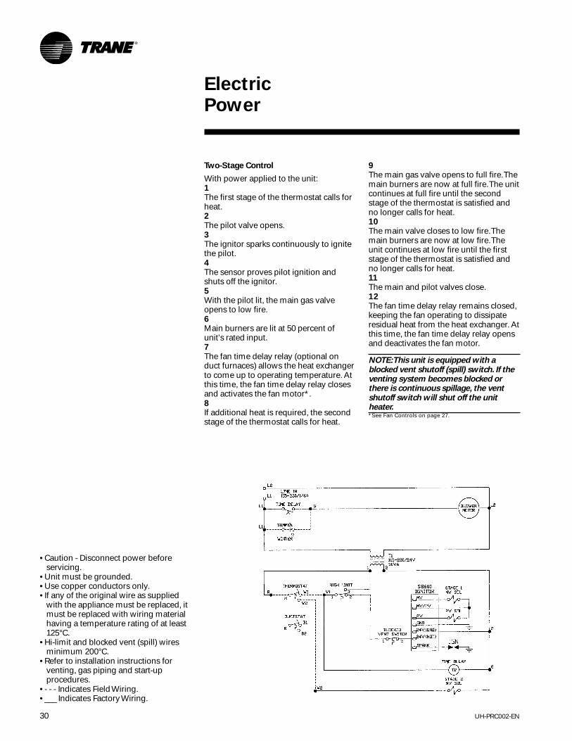
Two-Stage Control
With power applied to the unit:1The first stage of the thermostat calls forheat.2The pilot valve opens.3The ignitor sparks continuously to ignitethe pilot.4The sensor proves pilot ignition andshuts off the ignitor.5With the pilot lit, the main gas valveopens to low fire.6Main burners are lit at 50 percent ofunit’s rated input.7The fan time delay relay (optional onduct furnaces) allows the heat exchangerto come up to operating temperature. Atthis time, the fan time delay relay closesand activates the fan motor*.8If additional heat is required, the secondstage of the thermostat calls for heat.
9The main gas valve opens to full fire. Themain burners are now at full fire. The unitcontinues at full fire until the secondstage of the thermostat is satisfied andno longer calls for heat.10The main valve closes to low fire. Themain burners are now at low fire. Theunit continues at low fire until the firststage of the thermostat is satisfied andno longer calls for heat.11The main and pilot valves close.12The fan time delay relay remains closed,keeping the fan operating to dissipateresidual heat from the heat exchanger. Atthis time, the fan time delay relay opensand deactivates the fan motor.
NOTE: This unit is equipped with ablocked vent shutoff (spill) switch. If theventing system becomes blocked orthere is continuous spillage, the ventshutoff switch will shut off the unitheater.*See Fan Controls on page 27.
• Caution - Disconnect power beforeservicing.
• Unit must be grounded.• Use copper conductors only.• If any of the original wire as supplied
with the appliance must be replaced, itmust be replaced with wiring materialhaving a temperature rating of at least125°C.
• Hi-limit and blocked vent (spill) wiresminimum 200°C.
• Refer to installation instructions forventing, gas piping and start-upprocedures.
• - - - Indicates Field Wiring.• ___ Indicates Factory Wiring.

31UH-PRC002-EN
ElectricPower
Hydraulic Modulating Control
With power applied to the unit:1The thermostat calls for heat. NOTE: If athermostat is not supplied, steps 2through 5 will be constant as long aspower is applied to the unit.2The pilot valve opens.3The ignitor sparks continuously to ignitethe pilot.4The sensor proves pilot ignition andshuts off the ignitor.5With the pilot lit, the main electric gasvalve opens. At this time, the fan timedelay (optional on duct furnaces) isenergized. The fan time delay relaycloses and activates the fan motor.
NOTE: The unit firing is controlled by thehydraulic sensing bulb on themechanical valve. The mechanicallyoperated valve (not illustrated) is inseries with the single-stage electricallyoperated valve.
6The hydraulic sensing bulb, on themechanical modulating valve, calls forheat.
• Caution - Disconnect power beforeservicing.
• Unit must be grounded.• Use copper conductors only.• If any of the original wire as supplied
with the appliance must be replaced, itmust be replaced with wiring materialhaving a temperature rating of at least125°C.
• Hi-limit and blocked vent (spill) wiresminimum 200°C.
• Refer to installation instructions forventing, gas piping and start-upprocedures.
• - - - Indicates Field Wiring.• ___ Indicates Factory Wiring.
7The mechanical modulating valve opensallowing gas flow to the main burners.Main burners are lit at 50 percent of theunit’s rated input. The mechanicalmodulating valve modulates between 50percent and 100 percent of firing ratedepending on the temperature riserequired.8The unit continues to fire until thehydraulic sensing bulb is satisfied andno longer calls for heat.9The mechanical modulating valve closeswhich shuts off the main gas supply tothe burners.10The room thermostat is satisfied and nolonger calls for heat. The main and pilotvalves closes. At this time the fan timedelay relay opens and deactivates thefan motor.
NOTE: This unit is equipped with ablocked vent shutoff (spill) switch. If theventing system becomes blocked orthere is continuous spillage, the ventshutoff switch will shut off the unitheater.

UH-PRC002-EN32
ElectricPower
Sequence of Operation
Hydraulic Modulating Control
With Bypass
With power applied to the unit:1The thermostat calls for heat. NOTE: If athermostat is not supplied, steps 2through 5 will be constant as long aspower is applied to the unit.2The pilot valve opens.3The ignitor sparks continuously to ignitethe pilot.4The sensor proves pilot ignition andshuts off the ignitor.5With the pilot lit, the main electric gasvalve opens. At this time, the fan timedelay (optional on duct furnaces) isenergized. The fan time delay relaycloses and activates the fan motor.
NOTE: The unit firing is controlled by thehydraulic sensing bulb on themechanical valve. The mechanicallyoperated valve (not illustrated) is inseries with the single-stage electricallyoperated valve.
6The unit is equipped with a bypassmanifold containing a single-stageelectric valve which is in parallel with thehydraulic modulating gas valve. Thebypass is activated by a thermostat andoverrides the hydraulic control. Theoverride thermostat should be a remoteroom thermostat. If the temperature fallsbelow the override thermostat’s setpointthe thermostat opens the bypass valve,and the unit operates at full fire. The unitwill continue at full fire until the overridethermostat is satisfied and no longercalls for heat, at which point the bypass
valve is closed. The unit is againcontrolled by the hydraulic sensing bulbon the mechanical valve.7The hydraulic sensing bulb on themechanical valve calls for heat.8The mechanical modulating valve opensallowing gas flow to the main burners.Main burners are lit at 50 percent of theunit’s rated input. The mechanicalmodulating valve modulates between 50percent and 100 percent of firing rate,depending on the temperature riserequired.9The unit continues to fire until thehydraulic sensing bulb is satisfied andno longer calls for heat.10The mechanical modulating valve closesshutting off the main gas supply to theburners.11The room thermostat is satisfied and nolonger calls for heat. The main and pilotvalves closes. At this time the fan timedelay relay opens and deactivates thefan motor.

33UH-PRC002-EN
ElectricPower
Sequence of Operation
L2
L1DISCONNECT
LINE IN 115V/1/60
L1
L2
B
B
FAN TIME DELAY
SUMMER/WINTER SWITCH
SW
BLACK
BLACK
K5
BLOWERMOTOR
DRAFTORHTR
DRAFTOR WIRING FORPOWER VENTED UNITS
L1 L2 LINE TO24V XFORMER50 VA
1 22
24VOLTS
FAN TIME DELAY
DLDL
R1
W1
FURNACE ONE HIGH LIMIT
1 2
1
V
2
58600 IGNITOR
MV
MV/PV
PV
GND24V (GND)
24V (HOT)
SPARK
BLKQVENT
1 2
DRAFTOREND SW MV SOL.
PV SOL.
DRAFTOR ONE
K5
BYPASS SOL.OVERRIDE STAT
R W
IGN
BY1
V 2W1
DL
1
1
THERMOSTATOR DUCTSTAT
R W/B
Hydraulic Modulating Control With Bypass

UH-PRC002-EN34
ElectricPower
Sequence of Operation
Electronic Modulating Control
(with duct thermostat)
With power applied to the unit:1The thermostat calls for heat.2The pilot valve opens.3The ignitor sparks continuously to ignitethe pilot.4The sensor proves pilot ignition andshuts off the ignitor.5With the pilot lit, the gas valve opens.6Main burners are lit at 100 percent ofunit’s rated input.7The fan time delay relay (optional onduct furnaces) allows the heat exchangerto come up to operating temperature. Atthis time, the fan time delay relay closesand activates the fan motor.8The unit is controlled by the ductthermostat which modulates the unitfrom 100 to 50 percent of unit’s ratedinput. An amplifier receives a smallelectrical signal from the thermostat andconverts this into a working voltage. Thisworking voltage determines the positionof the modulating valve. With no voltageapplied to the valve, the valve will be fullopen and full fire will occur. Asincreasing voltage is applied to the valve,the valve will modulate closed. Atapproximately 12V dc, the valve willbe at its minimum low fire position. If thevoltage continues to increase, indicatinga further reduction in the unit’s firing isrequired, the increased voltage closes arelay which closes the automatic gasvalve. As temperature drops, the voltagealso drops causing the relay to re-openthe valve. The unit will continue to cyclein this manner until either an increase inthe unit’s firing rate is required or thethermostat is satisfied and no longercalls for heat.
9When the thermostat is satisfied, themain and pilot valves close.10The fan time delay relay (optional onduct furnaces) remains closed keepingthe fan motor operating to dissipateresidual heat from the heat exchanger. Atthis time, the fan time delay relay opensand deactivates the fan motor.11If optional room override thermostat isordered…when setpoint is reached, itwill cause the unit to go to full-fire,overriding both the duct sensor and theremote setpoint adjustment.
**NOTE: Sensor and selector wires toamplifier must not be run close to, or inconduit with, power or ignition wires.

35UH-PRC002-EN
ElectricPower
Sequence of Operation
t˚
L2
L1
DISCONNECT
LINE IN 115V/1/60
L1 FAN TIME DELAY
SUMMER/WINTER SWITCH
WS
8
8
L2
BLACK
BLACK
K5
BLOWERMOTOR
DRAFTORHTR
DRAFTOR WIRING FORPOWER VENTED UNITS
L2 LINE 24V XFORMER50 VA
24VOLTS
1 22
FAN TIME DELAY
DL
DL
R1
W1
L1
1
FURNACE ONE HIGH LIMIT
321
V
2
58600 IGNITOR
MV
MV/PV
PVGND24V (GND)
24V (HOT)SPARK
BLKD.VENT
IGN
1 2
DRAFTOREND SW MV SOL.
PV SOL.
DRAFTOR ONE
K5
VW1
DL
2
1
1
TS121 TD1212 1
MAXITROLW/ DUCT SENSING
4
3
14
1
57
9108
11MR
1
ONEHR VALVE
PERFURNACESECTION
USEA1010 FOR
SINGLE FUNACEA1011 FOR
MULTIPLE FURNACE
2
Electronic Modulating Control
(with duct thermostat)

UH-PRC002-EN36
ElectricPower
Sequence of Operation
Electronic Modulating Control(with room thermostat)
With power applied to the unit:1The thermostat calls for heat.2The pilot valve opens.3The ignitor sparks continuously to ignitethe pilot.4The sensor proves pilot ignition andshuts off the ignitor.5With the pilot lit, the gas valve opens.6Main burners are lit at 100 percent ofunit’s rated input.7The fan time delay relay (optional onduct furnaces) allows the heat exchangerto come up to operating temperature. Atthis time, the fan time delay relay closesand activates the fan motor.
8The unit is controlled by the electronicthermostat which modulates the unitfrom 100 to 50 percent of unit’s ratedinput. An amplifier receives a smallelectrical signal from the thermostat andconverts this into a working voltage. Thisworking voltage determines the positionof the modulating valve. With no voltageapplied to the valve, the valve will be fullopen and full fire will occur. Asincreasing voltage is applied to the valve,the valve will modulate closed. Atapproximately 12V dc, the valve willbe at its minimum low fire position. If thevoltage continues to increase, indicatinga further reduction in the unit’s firing isrequired, the increased voltage closes arelay which closes the automatic gasvalve. As temperature drops, the voltagealso drops causing the relay to re-openthe valve. The unit will continue to cyclein this manner until either an increase inthe unit’s firing rate is required or thethermostat is satisfied and no longercalls for heat.9When the room thermostat is satisfied,the main and pilot valves close.10The fan time delay relay (optional onduct furnaces) remains closed keepingthe fan motor operating to dissipateresidual heat from the heat exchanger. Atthis time, the fan time delay relay opensand deactivates the fan motor.

37UH-PRC002-EN
ElectricPower
Sequence of Operation
Electronic Modulating Control
(with room thermostat)
L2
L1DISCONNECT
LINE IN 115V/1/60
L1 FAN TIME DELAY
SUMMER/WINTER SWITCH
WS
8
8
L2
BLOWERMOTOR
DRAFTORMTR
K5BLACK
BLACK
2
FAN TIME DEALY
DL
L2L1
115V TO24V XFORMER50 VA
2124
VOLTS
FURNACE ONE HIGH LIMIT
1 23 R1
DL
W1
DRAFTOR ONE
K5
MV SOL.
PV SOL.
58600 IGNITOR
MV
MV/PV
PVGND24V (GND)
24V (HOT)SPARK
PRESS. SW.
IGN
V 2W1
DL
2
V
1
1
MAXITROLW/ROOM SENSING
4
3
5 9108
11
7
1
3
1
7
9
T107ATSTAT
USEA1010 FOR
SINGLE FURNACEA1011 FOR
MULTIPLE FURNACE
2
ONEHR VALVE
PERFURNACESECTION
MR
1
1
2

UH-PRC002-EN38
ElectricPower
High-Efficiency Units
NOTE: On duct furnaces, the fan motorand associated controls shown in thewiring diagrams are not integral to theunit. It is essential, however, that the airhandling system be interlocked with theduct furnace to prevent duct furnaceoperation without airflow.
Single-Stage Control
With power applied to the unit:1The thermostat calls for heat.2The pressure switch measures the flowthrough the vent system and energizesthe intermittent pilot when the flow iscorrect. CAUTION: THE PRESSURESWITCH MUST NOT BE BYPASSED.THE UNIT MUST NOT BE FIRED UNLESSTHE FLUE VENT FAN IS OPERATING. Ifthis procedure is not followed, there maybe a gas buildup that could cause anexplosion.3The pressure switch closes and activatesthe flue vent fan.4The pilot valve opens.5The ignitor sparks continuously to ignitethe pilot.
6The sensor proves pilot ignition andshuts off the ignitor.7With the pilot lit, the main gas valveopens.8Main burners are lit at 100 percent of theunit’s rated input.9The fan time delay relay allows theheater to come up to operatingtemperature. At this time, the fan timedelay relay closes and activates the fanmotor.10The unit continues to fire until thethermostat is satisfied and no longercalls for heat.11The main and pilot valve close.12The pressure switch opens anddeactivates the flue vent fan.13The fan time delay relay remains closed,keeping the fan operating to dissipateresidual heat from the heat exchanger. Atthis time, the fan time delay relay opensand deactivates the fan motor.
• Caution - Disconnect power beforeservicing.
• Unit must be grounded.• Use copper conductors only.• If any of the original wire as supplied
with the appliance must be replaced, itmust be replaced with wiring materialhaving a temperature rating of at least125°C.
• Hi-limit and blocked vent (spill) wiresminimum 200°C.
• Refer to installation instructions forventing, gas piping and start-upprocedures.
• - - - Indicates Field Wiring.• ___ Indicates Factory Wiring.
L2
L1
L1
L1
L1
8
LINE IN115-240/1/60
TIME DELAY
SUMMER
WINTER
RELAY 1
L2
L2
BLOWERMOTOR
T1115-240/24V50VA
DRAFTORMTR.
21
R
R W
WTHERMOSTAT
HIGH LIMIT
132
DRAFTORPRESS. SW. 58600
IGNITOR MV SOL.MV
MV/PV
PV
GND
24V (HOT)24V (GND)
SPARKIGN
PV SOL.
RELAY 1
R
TIME DELAY
TD

39UH-PRC002-EN
ElectricPower
Separated Combustion Units
Single-Stage Control
With power applied to the unit:1The thermostat calls for heat.2The pressure switch measures thepressure differential between the air inletand exhaust vent systems. If thedifferential is correct, the intermittentpilot ignition is energized. CAUTION: THEPRESSURE SWITCH MUST NOT BEBYPASSED. THE UNIT MUST NOT BEFIRED UNLESS THE FLUE VENT FAN ISOPERATING.
3When the pressure switch is closed, thepower venter motor is energized.4The pilot valve opens.5The ignitor sparks continuously to ignitethe pilot.6The sensor proves pilot ignition andshuts off the ignitor.7With the pilot lit, the main gas valveopens.8Main burners are lit at 100 percent of theunit’s rated input.
9The fan time delay relay allows theheater to come up to operatingtemperature. At this time, the fan timedelay relay closes and activates the fanmotor.10The unit continues to fire until thethermostat is satisfied and no longercalls for heat.11The main and pilot valve close.12The pressure switch opens anddeactivates the flue vent fan.13The fan time delay relay remains closed,keeping the fan operating to dissipateresidual heat from the heat exchanger. Atthis time, the fan time delay relay opensand deactivates the fan motor.
• Caution - Disconnect power beforeservicing.
• Unit must be grounded.• Use copper conductors only.• If any of the original wire as supplied
with the appliance must be replaced, itmust be replaced with wiring materialhaving a temperature rating of at least125°C.
• Hi-limit and blocked vent (spill) wiresminimum 200°C.
• Refer to installation instructions forventing, gas piping and start-upprocedures.
• - - - Indicates Field Wiring.• ___ Indicates Factory Wiring.
L2
L1
DISCONNECT
LINE IN 115/1/60
L1 FAN TIME DELAY
L2
8
BLOWER/FANMOTOR
MTR
DRAFTORMOTOR
MTRK5BLACK
BLACK
LINE TO24V XFORMER50 VA
L2
8
1 224
VOLTS
2
SUMMER/WINTER SWITCH
WS
L1
FAN TIME DELAY
DL
DRAFTOR ONE
K5
MV SOL.
PV SOL.
58600 IGNITORMV
MV/PV
PVGND24V (GND)
24V (HOT)SPARK
PRESS. SW.
IGN1
2
V
W1
R1
DL
HIGH LIMIT 1
132
1 W1
DL
V 2
T/D STAT
R W/B
1

UH-PRC002-EN40
Table EP-1 — Motor Electrical Data — Centrifugal Fan
Current Full Load Amps*Characteristics ¼hp 1/3hp ½hp ¾hp 1hp
115/60/1 5.0 5.9 7.2 11.0 14.0230/60/1 2.5 3.3 3.9 5.5 7.0208/60/3 NR NR 2.7 3.1 4.0230/60/3 NR NR 2.4 2.8 3.6460/60/3 NR NR 1.2 1.4 1.8
*FLA based on NEC ratings. All motors are 1725 rpm.NR = Motor available, but not rated by NEC.
Table EP-2 — Motor Electrical Data — Horizontal Blower
Current Full Load Amps*Characteristics ½hp ½hp ¾hp 1hp 1½hp 2hp 3hp
115/60/1 5.9 7.2 11.0 14.0 16.4 24.6 34.0230/60/1 3.3 3.9 5.5 7.0 8.2 12.3 17.0208/60/3 NR 2.7 3.1 4.0 4.9 6.4 9.2230/60/3 NR 2.4 2.8 3.6 4.4 5.8 8.6460/60/3 NR 1.2 1.4 1.8 2.2 2.9 4.3
Motor wt. (LB) 18 33 33 36 39 40 44*FLA based on NEC ratings. All motors are 1,725 rpm.NR = motor available, but not rated by NEC.
ElectricPower
Separated Combustion Units
Single-Stage Control
Electronic Modulating 4-20 mA/0-10 VDCInput
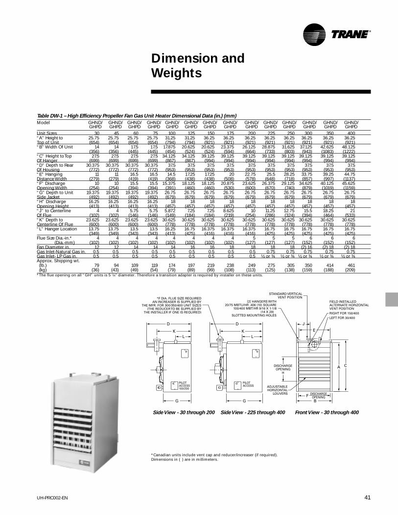
41UH-PRC002-EN
Table DW-1 – High Efficiency Propeller Fan Gas Unit Heater Dimensional Data (in.) (mm)
Model GHND/ GHND/ GHND/ GHND/ GHND/ GHND/ GHND/ GHND/ GHND/ GHND/ GHND/ GHND/ GHND/ GHND/GHPD GHPD GHPD GHPD GHPD GHPD GHPD GHPD GHPD GHPD GHPD GHPD GHPD GHPD
Unit Sizes 30 45 60 75 100 125 150 175 200 225 250 300 350 400“A” Height to 25.75 25.75 25.75 25.75 31.25 31.25 36.25 36.25 36.25 36.25 36.25 36.25 36.25 36.25Top of Unit (654) (654) (654) (654) (794) (794) (921) (921) (921) (921) (921) (921) (921) (921)“B” Width Of Unit 14 14 17.5 17.5 17.875 20.625 20.625 23.375 26.125 28.875 31.625 37.125 42.625 48.125
(356) (356) (445) (445) (454) (524) (524) (594) (664) (733) (803) (943) (1083) (1222)“C” Height to Top 27.5 27.5 27.5 27.5 34.125 34.125 39.125 39.125 39.125 39.125 39.125 39.125 39.125 39.125Of Hanger (699) (699) (699) (699) (867) (867) (994) (994) (994) (994) (994) (994) (994) (994)“D” Depth to Rear 30.375 30.375 30.375 30.375 37.5 37.5 37.5 37.5 37.5 37.5 37.5 37.5 37.5 37.5Of Housing (772) (772) (772) (772) (953) (953) (953) (953) (953) (953) (953) (953) (953) (953)“E” Hanging 11 11 16.5 16.5 14.5 17.25 17.25 20 22.75 25.5 28.25 33.75 39.25 44.75Distance Width (279) (279) (419) (419) (368) (438) (438) (508) (578) (648) (718) (857) (997) (1137)“F” Discharge 10 10 15.5 15.5 15.375 18.125 18.125 20.875 23.625 26.375 29.125 34.625 40.125 45.625Opening Width (254) (254) (394) (394) (391) (460) (460) (530) (600) (670) (740) (879) (1019) (1159)“G” Depth to Unit 19.375 19.375 19.375 19.375 26.75 26.75 26.75 26.75 26.75 26.75 26.75 26.75 26.75 26.75Side Jacket (492) (492) (492) (492) (679) (679) (679) (679) (679) (679) (679) (679) (679) (679)“H” Discharge 16.25 16.25 16.25 16.25 18 18 18 18 18 18 18 18 18 18Opening Height (413) (413) (413) (413) (457) (457) (457) (457) (457) (457) (457) (457) (457) (457)“J” to Centerline 4 4 5.75 5.75 5.872 7.25 7.25 8.625 10 11.25 12.75 15.5 18.25 21Of Flue (102) (102) (146) (146) (149) (184) (184) (219) (254) (286) (324) (394) (464) (533)“K” Depth to 23.625 23.625 23.625 23.625 30.625 30.625 30.625 30.625 30.625 30.625 30.625 30.625 30.625 30.625Centerline Of Flue (600) (600) (600) (600) (778) (778) (778) (778) (778) (778) (778) (778) (778) (778)“L” Hanger Location 13.75 13.75 13.5 13.5 16.25 16.75 16.375 16.375 16.375 16.75 16.75 16.75 16.75 16.75
(349) (349) (343) (343) (413) (425) (416) (416) (416) (425) (425) (425) (425) (425)Flue Size Dia.-in.* 4 4 4 4 4 4 4 4 5 5 5 6 6 6 (Dia.-mm) (102) (102) (102) (102) (102) (102) (102) (102) (127) (127) (127) (152) (152) (152)Fan Diameter in. 12 12 14 14 14 16 16 18 18 18 18 (2) 16 (2) 18 (2) 18Gas Inlet-Natural Gas in. 0.5 0.5 0.5 0.5 0.5 0.5 0.5 0.5 0.5 0.75 0.75 0.75 0.75 0.75Gas Inlet- LP Gas in. 0.5 0.5 0.5 0.5 0.5 0.5 0.5 0.5 0.5 ½ or ¾ ½ or ¾ ½ or ¾ ½ or ¾ ½ or ¾Approx. Shipping wt.(lb.) 79 94 109 119 174 197 219 238 249 275 305 350 414 461(kg) (36) (43) (49) (54) (79) (89) (99) (108) (113) (125) (138) (159) (188) (209)
*The flue opening on all “GH” units is 5 1/8" diameter. Therefore a transition adapter is required by installer on these units.
Dimension andWeights
*Canadian units include vent cap and reducer/increaser (if required).Dimensions in ( ) are in millimeters.
Side View - 30 through 200 Side View - 225 through 400 Front View - 30 through 400

UH-PRC002-EN42
Dimension andWeights
Table DW-2 – High-Efficiency Centrifugal Fan Unit Heater Dimensional Data (in.) (mm)
Model GBND/ GBND/ GBND/ GBND/ GBND/ GBND/ GBND/ GBND/ GBND/ GBND/GBPD GBPD GBPD GBPD GBPD GBPD GBPD GBPD GBPD GBPD
Unit Size 100 125 150 175 200 225 250 300 350 400“A” Height to 31.25 31.25 36.25 36.25 36.25 36.25 36.25 36.25 36.25 36.25Top of Unit (794) (794) (921) (921) (921) (921) (921) (921) (921) (921)“B” Width 17.875 20.625 20.625 23.375 26.125 28.875 31.625 37.125 42.625 48.125Of Unit (454) (524) (524) (594) (664) (733) (803) (943) (1083) (1222)“C” Height to 34.125 34.125 39.125 39.125 39.125 39.125 39.125 39.125 39.125 39.125Top of Hanger (867) (867) (994) (994) (994) (994) (994) (994) (994) (994)“D” Depth to 42.625 44.25 44.25 47 47 51 51 48.25 51 51Rear of Housing (1083) (1124) (1124) (1194) (1194) (1295) (1295) (1226) (1295) (1295)“E” Hanging 14.5 17.25 17.25 20 22.75 25.5 28.25 33.75 39.25 44.75Distance Width (368) (438) (438) (508) (578) (648) (718) (857) (997) (1137)“F” Discharge 15.375 18.125 18.125 20.875 23.625 26.375 29.125 34.625 40.125 45.625Opening Width (391) (460) (460) (530) (600) (670) (740) (879) (1019) (1159)“J” To Centerline 5.875 7.25 7.25 8.625 10 11.25 12.75 15.5 18.25 21Of Flue (149) (184) (184) (219) (254) (286) (324) (394) (464) (533)“L” Hanger 16.375 16.375 16.375 16.375 16.375 16.375 16.375 16.375 16.375 16.375Location (416) (416) (416) (416) (416) (416) (416) (416) (416) (416)“M” Hanging 16.375 16.375 16.375 17.875 17.875 21.875 21.875 21.875 21.875 21.875Distance Depth (416) (416) (416) (454) (454) (556) (556) (556) (556) (556)Flue Size (Dia-in.) * 4 4 4 4 5 5 5 6 6 6 (Dia-mm) (102) (102) (102) (102) (127) (127) (127) (152) (152) (152)Blower Size (in.) 9 10 10 12 12 12 12 (2) 10 (2) 12 (2) 12Gas Inlet-Natural Gas (in.) 0.5 0.5 0.5 0.5 0.5 0.75 0.75 0.75 0.75 0.75Gas Inlet- LP Gas (in.) 0.5 0.5 0.5 0.5 0.5 ½ or ¾ ½ or ¾ ½ or ¾ ½ or ¾ ½ or ¾Approx. Shipping wt. (lb.) 262 279 314 336 363 408 427 471 561 594 (kg) (119) (127) (142) (152) (165) (185) (194) (214) (254) (269)*The flue opening on all “GB” units is 5 1/8" diameter. Therefore a transition adapter is required by installer on these units.
*Canadian units include vent cap and reducer/increaser (if required).Dimensions in ( ) are in millimeters.
Side View - 100 through 200 Side View - 225 through 400 Front View - 100 through 400

43UH-PRC002-EN
Dimension andWeights
Table DW-3 – Separated Combustion – Propeller Fan Gas Unit Heater Dimensional Data (in.) (mm)
Model GAND/ GAND/ GAND/ GAND/ GAND/ GAND/ GAND/ GAND/ GAND/ GAND/GAPD GAPD GAPD GAPD GAPD GAPD GAPD GAPD GAPD GAPD
Unit Size 100 125 150 175 200 225 250 300 350 400“A” Height to 31.25 31.25 36.25 36.25 36.25 36.25 36.25 36.25 36.25 36.25Top of Unit (794) (794) (921) (921) (921) (921) (921) (921) (921) (921)“B” Height to 34.062 34.062 39.062 39.062 39.062 39.062 39.062 39.062 39.062 39.062Top of Hanger (865) (865) (992) (992) (992) (992) (992) (992) (992) (992)“C” Hanging 14.75 17.5 17.5 20.25 23 25.75 28.5 34 39.5 45Distance Width (375) (445) (445) (514) (584) (654) (724) (864) (1003) (1143)“D” Discharge 15.375 18.125 18.125 20.875 23.625 26.375 29.125 34.625 40.125 45.625Opening Width (391) (460) (460) (530) (600) (670) (740) (879) (1019) (1159)“E” Width 17.875 20.625 20.625 23.375 26.125 28.875 31.625 37.125 42.625 48.125Of Unit (454) (524) (524) (594) (664) (733) (803) (943) (1083) (1222)“F” To Centerline 5.875 7.25 7.25 8.625 10 11.25 12.75 15.5 18.25 21Of Flue (149) (184) (184) (219) (254) (286) (324) (394) (464) (533)Flue Size Dia.-in. 4 4 4 4 5 5 5 6 6 6 (Dia.-mm) (102) (102) (102) (102) (127) (127) (127) (152) (152) (152)Fan Diameter (in.) 14 16 16 18 18 18 18 (2)16 (2)18 (2)18Gas Inlet-Natural Gas (in.) 0.5 0.5 0.5 0.5 0.5 0.75 0.75 0.75 0.75 0.75Gas Inlet- LP Gas (in.) 0.5 0.5 0.5 0.5 0.5 ½ or ¾ ½ or ¾ ½ or ¾ ½ or ¾ ½ or ¾Approx. Shipping wt. (lb.) 200 228 256 284 312 340 368 432 488 545 (kg) (91) (103) (116) (129) (142) (154) (167) (196) (221) (247)*The flue openings on all units are 5 1/8” diameter. Therefore, a transition adapter is required by installer on these units.
Side View - 100 through 200 Side View - 225 through 400
NOTE: Air intake is round on 225/250 units. For 300/400 units, airintake is as shown.
Front View - 100 through 400
*Canadian units include vent cap and reducer/increaser (if required).Dimensions in ( ) are in millimeters.

UH-PRC002-EN44
Dimension andWeights
Table DW-4 – Separated Combustion – Centrifugal Fan Unit Heater Dimensional Data
Model GKND/ GKND/ GKND/ GKND/ GKND/ GKND/ GKND/ GKND/ GKND/ GKND/GKPD GKPD GKPD GKPD GKPD GKPD GKPD GKPD GKPD GKPD
Unit Size 100 125 150 175 200 225 250 300 350 400“A” Height to Top 31.25 31.25 36.25 36.25 36.25 36.25 36.25 36.25 36.25 36.25Top of Unit (794) (794) (921) (921) (921) (921) (921) (921) (921) (921)“B” Height to Top 34.062 34.062 39.062 39.062 39.062 39.062 39.062 39.062 39.062 39.062Top of Hanger (865) (865) (992) (992) (992) (992) (992) (992) (992) (992)“C” Hanging 14.75 17.5 17.5 20.25 23 25.75 28.5 34 39.5 45Distance Width (375) (445) (445) (514) (584) (654) (724) (864) (1003) (1143)“D” Discharge 15.375 18.125 18.125 20.875 23.625 26.375 29.125 34.625 40.125 45.625Opening Width (391) (460) (460) (530) (600) (670) (740) (879) (1019) (1159)“E” Width 17.875 20.625 20.625 23.375 26.125 28.875 31.625 37.125 42.625 48.125Of Unit (454) (524) (524) (594) (664) (733) (803) (943) (1083) (1222)“F” To Centerline 5.875 7.25 7.25 8.625 10 11.25 12.75 15.5 18.25 21Of Flue (149) (184) (184) (219) (254) (286) (324) (394) (464) (533)“G” Hanging 18.5 18.5 18.5 20 20 23 23 23 23 23Distance Depth (470) (470) (470) (508) (508) (584) (584) (584) (584) (584)“H” Depth to 42.75 44.375 44.375 47.187 47.187 50.875 48 50.875 50.875 51Rear of Housing (1086) (1127) (1127) (1199) (1199) (1292) (1219) (1292) (1292) (1295)Flue Size (Dia-in.) 4 4 4 4 5 5 5 6 6 6 (Dia-mm) (102) (102) (102) (102) (127) (127) (127) (152) (152) (152)Blower Size (in) 9 10 10 12 12 12 12 (2) 10 (2) 12 (2) 12Gas Inlet-Natural Gas (in.) 0.5 0.5 0.5 0.5 0.5 0.75 0.75 0.75 0.75 0.75Gas Inlet- LP Gas (in.) 0.5 0.5 0.5 0.5 0.5 ½ or ¾ ½ or ¾ ½ or ¾ ½ or ¾ ½ or ¾Approx. Shipping wt. (lb.) 298 330 362 394 426 458 490 558 618 678 (kg) (135) (150) (164) (179) (193) (208) (222) (253) (280) (308)*The flue openings on all units are 51/8" diameter. Therefore, a transition adaptor is required by installer on these units.
*Canadian units include vent cap and reducer/increaser (if required).Dimensions in ( ) are in millimeters.
Side View - 100 through 200 Side View - 225 through 400
NOTE: Air intake is round on 225/250units. For 300/400 units, air intake isas shown.
Front View - 100 through 400

45UH-PRC002-EN
Dimension andWeights
Table DW-5 – Propeller Fan Gas Unit Heater Dimensional Data (in.) (mm)
Model GPND/ GPND/ GPND/ GPND/ GPND/ GPND/ GPND/ GPND/ GPND/ GPND/ GPND/ GPND/ GPND/ GPND/GPPD GPPD GPPD GPPD GPPD GPPD GPPD GPPD GPPD GPPD GPPD GPPD GPPD GPPD
Unit Size 30 45 60 75 100 125 150 175 200 225 250 300 350 400“A” Height to 25.75 25.75 25.75 25.75 31.25 31.25 36.25 36.25 36.25 36.25 36.25 36.25 36.25 36.25Top of Unit (654) (654) (654) (654) (794) (794) (921) (921) (921) (921) (921) (921) (921) (921)“B” Width of Unit 14 14 17.5 17.5 17.875 20.625 20.625 23.375 26.125 28.875 31.625 37.125 42.625 48.125
(356) (356) (445) (445) (454) (524) (524) (594) (664) (733) (803) (943) (1083) (1222)“C” Height to 27.5 27.5 27.5 27.5 33.25 33.25 38.25 38.25 38.25 39.125 39.125 39.125 39.125 39.125Top of Hanger (699) (699) (699) (699) (845) (845) (972) (972) (972) (994) (994) (994) (994) (994)“D” Depth to 27.625 27.625 27.625 27.625 32.5 32.5 36 36 36 38.25 38.25 37.75 38.25 38.25Rear of Housing (702) (702) (702) (702) (826) (826) (914) (914) (914) (972) (972) (959) (972) (972)“E” Hanging 8.625 8.625 14.125 14.125 14.75 17.5 17.5 20.25 23 25.5 28.25 33.75 39.25 44.75Distance Width (219) (219) (359) (359) (375) (445) (445) (514) (584) (648) (718) (857) (997) (1137)“F” Discharge 10 10 15.5 15.5 15.375 18.125 18.125 20.875 23.6256 26.375 29.125 34.625 40.125 45.625Opening Width (254) (254) (394) (394) (391) (460) (460) (530) (600) (670) (740) (879) (1019) (1159)“G” Depth to Unit 19.375 19.375 19.375 19.375 26.75 26.75 26.75 26.75 26.75 26.75 26.75 26.75 26.75 26.75Side Jacket (492) (492) (492) (492) (679) (679) (679) (679) (679) (679) (679) (679) (679) (679)“H” Discharge 16.25 16.25 16.25 16.25 18 18 18 18 18 18 18 18 18 18Opening Height (413) (413) (413) (413) (457) (457) (457) (457) (457) (457) (457) (457) (457) (457)“L” Hanger 11.875 11.875 11.5 11.5 15.125 15.125 15.125 15.125 15.125 16.25 16.25 16.25 16.25 16.25Location (302) (302) (292) (292) (384) (384) (384) (384) (384) (413) (413) (413) (413) (413)“S” Flue Size (Dia-in.) 4 4 5 5 6 6 7 7 8 8 8 10 10 12
(Dia-mm) (102) (102) (127) (127) (152) (152) (178) (178) (203) (203) (203) (254) (254) (305)Flue Type* R,V R,V R,V R,V R,V R,V R,H R,H R,H R,H R,H OV,H OV,H OV,#Fan Diameter (in.) 12 12 14 14 14 16 16 18 18 18 18 (2) 16 (2) 18 (2) 18Gas Inlet-Natural Gas (in.) 0.5 0.5 0.5 0.5 0.5 0.5 0.5 0.5 0.5 0.75 0.75 0.75 0.75 0.75Gas Inlet- LP Gas (in.) 0.5 0.5 0.5 0.5 0.5 0.5 0.5 0.5 0.5 ½ or ¾ ½ or ¾ ½ or ¾ ½ or ¾ ½ or ¾Approx. Shipping wt. (lb.) 72 82 98 104 178 200 209 232 242 279 301 356 415 451 (kg) (33) (37) (44) (47) (81) (91) (95) (105) (110) (127) (137) (161) (188) (205)Net Unit wt. (lb.) 59 69 84 90 148 168 175 196 216 239 261 304 340 376(kg) (27) (31) (38) (41) (67) (76) (79) (89) (98) (108) (118) (138) (154) (171)*R – Round, OV – Oval. Refer to detail above for 400 MBh unit.
Side View - 30 through 200 Side View - 225 through 400 Front View - 30 through 400
Dimensions are in inches.(Dimensions in parentheses are in mm.)

UH-PRC002-EN46
Dimension andWeights
Table DW-6 – Tubular Heat Exchanger Dimensional Data (in.) (mm)
Model GTND/GTPD GTND/GTPD GTND/GTPD GTND/GTPD GTND/GTPDUnit Size 003 004 006 007 009“A” Height to Top of Unit 12 12 17.75 17.75 17.75
(305) (305) (451) (451) (451)“B” Height to Top of Hanger 13 13 18.75 18.75 18.75
(330) (330) (476) (476) (476)“C” Overall Depth 25.5 25.5 26.75 26.75 26.75
(648) (648) (679) (679) (679)Center Line Height of Flue 7.25 7.25 10.5 10.5 10.5
(184) (184) (267) (267) (267)Center Line Electric Connection 10.25 10.25 16 16 16
(260) (260) (406) (406) (406)“ F” Discharge Opening Height 10.5 10.5 16.25 16.25 16.25
(267) (267) (413) (413) (413)“G” Fan Diameter-in. 10 10 16 16 16Unit Weight
(lbs.) 62 68 87 93 93(kgs.) (28) (31) (39) (42) (42)
Shipping Weight(lbs.) 72 78 102 108 108(kgs.) (33) (35) (46) (49) (49)
Dimensions are in inches.(Dimensions in parentheses are in mm.)
Rear View Side View Front View
Top View

47UH-PRC002-EN
Dimension andWeights
Table DW-7 – Tubular Heat Exchanger Unit Heater Dimensional Data (in.) (mm)
Gas Gas Unit ShippingModels Input Flue Fan Inlet Inlet Weight Weight
GTND/GTPD MBh A B C D E F G H L Dia. Dia Nat. LP lbs. (kg) lbs. (kg)010 100.0 33¾ 20¾ 133/8 11 185/8 18¾ 4¾ 24½ 25¼ 5 16 ½ ½ 133 173
(857) (527) (340) (279) (473) (476) (121) (622) (641) (127) (60) (78)012 125.0 33¾ 20¾ 133/8 11 185/8 18¾ 4¾ 24½ 25¼ 5 16 ½ ½ 145 185
(857) (527) (340) (279) (473) (476) (121) (622) (641) (127) (66) (84)015 150.0 33¾ 20¾ 133/8 11 185/8 18¾ 4¾ 24½ 25¼ 5 16 ½ ½ 155 195
(857) (527) (340) (279) (473) (476) (121) (622) (641) (127) (70) (88)017 175.0 33¾ 32¾ 193/8 11 305/8 30¾ 4¾ 24½ 37¼ 5 18 ½ ½ 191 241
(857) (831) (492) (279) (778) (781) (121) (622) (946) (127) (87) (109)020 200.0 33¾ 32¾ 193/8 11 305/8 30¾ 4¾ 24½ 37¼ 5 18 ½ ½ 201 251
(857) (831) (492) (279) (778) (781) (121) (622) (946) (127) (91) (114)025 250.0 33¾ 32¾ 193/8 11 305/8 30¾ 4¾ 24½ 37¼ 5 18 ¾ ½ 211 261
(857) (831) (492) (279) (778) (781) (121) (622) (946) (127) (96) (118)
Rear View Side View Front View
Dimensions are in inches.(Dimensions in parentheses are in mm.)

UH-PRC002-EN48
Dimension andWeights
Table DW-8 – Tubular Heat Exchanger Unit Heater Dimensional Data (in.) (mm)
Gas Gas Unit ShippingModels Input Flue Fan Inlet Inlet Weight Weight
GTND/GTPD MBh A B C D E F G H L Dia. Dia Nat. LP lbs. (kg) lbs. (kg)030 300.0 34 50¾ 283/8 12¼ 485/8 48¾ 51/8 24½ 55¼ 6 (2) 16 ¾ ½ or 307 367
(864) (1289) (721) (311) (1235) (1238) (130) (622) (1403) (152) ¾ (139) (166)035 350.0 34 50¾ 283/8 12¼ 485/8 48¾ 51/8 24½ 55¼ 6 (2) 18 ¾ ½ or 321 381
(864) (1289) (721) (311) (1235) (1238) (130) (622) (1403) (152) ¾ (145) (173)040 400.0 34 50¾ 283/8 12¼ 485/8 48¾ 51/8 24½ 55¼ 6 (2) 18 ¾ ½ or 335 395
(864) (1289) (721) (311) (1235) (1238) (130) (622) (1403) (152) ¾ (152) (179)
Rear View
Side View Front View
Dimensions are in inches.(Dimensions in parentheses are in mm.)

49UH-PRC002-EN
Dimension andWeights
Table DW-9 – Centrifugal Fan Gas Unit Heater Dimensional Data (in.) (mm)
Model GCND/ GCND/ GCND/ GCND/ GCND/ GCND/ GCND/ GCND/ GCND/ GCND/GCPD GCPD GCPD GCPD GCPD GCPD GCPD GCPD GCPD GCPD
Unit Size 100 125 150 175 200 225 250 300 350 400“A” Height to Top of Unit 31.25 31.25 36.25 36.25 36.25 36.25 36.25 36.25 36.25 36.25
(794) (794) (921) (921) (921) (921) (921) (921) (921) (921)“B” Width of Unit 17.875 20.625 20.625 23.375 26.125 28.875 31.625 37.125 42.625 48.125
(454) (524) (524) (594) (664) (733) (803) (943) (1083) (1222)“C” Height to Top of 33.25 33.25 38.25 38.25 38.25 38.25 38.25 38.25 38.25 38.25Hanger (845) (845) (972) (972) (972) (972) (972) (972) (972) (972)“D” Depth to Rear of 42.625 44.25 44.25 47 47 51 51 48.25 51 51Housing (1083) (1124) (1124) (1194) (1194) (1295) (1295) (1226) (1295) (1295)“E” Hanging Distance 14.75 17.5 17.5 20.25 23 25.5 28.25 33.75 39.25 44.75Width (375) (445) (445) (514) (584) (648) (718) (857) (997) (1137)“F” Discharge Opening 15.375 18.125 18.125 20.875 23.6256 26.375 29.125 34.625 40.125 45.625Width (391) (460) (460) (530) (600) (670) (740) (879) (1019) (1159)“L” Hanger Location 15.125 15.125 15.125 15.125 15.125 16.25 16.25 16.25 16.25 16.25
(384) (384) (384) (384) (384) (413) (413) (413) (413) (413)M” Hanging Distance 24.625 25.875 17.5 19 19 21.875 21.875 27.875 28.875 28.875Depth (625) (657) (445) (483) (483) (556) (556) (708) (733) (733)“S” Flue Size Dia. 6 6 7 7 8 8 8 10 10 12
(152) (152) (178) (178) (203) (203) (203) (254) (254) (305)Flue Type * R,V R,V R,H R,H R,H R,H R,H OV,H OV,H OV,#Blower Size (in) 9 10 10 12 12 12 12 (2) 10 (2) 12 (2) 12Gas Inlet - Natural Gas (in.) 0.5 0.5 0.5 0.5 0.5 0.75 0.75 0.75 0.75 0.75Gas Inlet - LP Gas (in.) 0.5 0.5 0.5 0.5 0.5 ½ or ¾ ½ or ¾ ½ or ¾ ½ or ¾ ½ or ¾Approx. Shipping wt. (lb.) 253 270 315 335 351 396 415 459 550 582 (kg) (115) (122) (143) (152) (159) (180) (188) (208) (249) (264)* R = Round, OV = Oval. Refer to Detail A above for 400 MBh unit.
Side View -100 through 200 Side View - 225 through 400 Front View - 100 through 400
*Discharge opening for optional Duct Flange Assembly.Dimensions in ( ) are in millimeters.

UH-PRC002-EN50
Side View - 100 through125 Side View - 150 through 400Front View - 100 through 400
Side View - 100 through125 Side View - 150 through 400Front View - 100 through 400
Dimension andWeights
Table DW-10 – Dimensional Data — Standard Duct Furnaces (in.) (mm)
ModelsGDND/ Input Gas Inlet WeightGDPD MBh A B C F S Nat. LP lb. (kg)
010 100 17.875 15.5 17.125 23.875 6 RV 0.5 0.5 162(454) (394) (435) (606) (152) RV (73)
012 125 20.625 18.25 19.875 26.625 6 RV 0.5 0.5 175(524) (464) (505) (676) (152) RV (79)
015 150 20.625 18.25 19.875 26.625 7 RH 0.5 0.5 186(524) (464) (505) (676) (178) RH (84)
017 175 23.375 21 22.625 29.375 7 RH 0.5 0.5 205(594) (533) (575) (746) (178) RH (93)
020 200 26.125 23.75 25.375 32,125 8 RH 0.5 0.5 221(664) (603) (645) (816) (203) RH (100)
022 225 28.875 26.5 28.125 34.875 8 RH 0.75 ½ or ¾ 243(733) (673) (714) (886) (203) RH (110)
025 250 31.625 29.25 30.875 37.625 8 RH 0.75 ½ or ¾ 252(803) (743) (784) (956) (203) RH (113)
030 300 37.125 34.75 36.375 43.125 10 OVH 0.75 ½ or ¾ 301(943) (883) (924) (1095) (254)OVH (137)
035 350 42.625 40.25 41.875 48.265 10 OVH 0.75 ½ or ¾ 378(1083) (1022) (1064) (1235) (254) ORH (171)
040 400 48.125 45.75 47.375 54.125 12 OVH 0.75 ½ or ¾ 392(1222) (1162) (1203) (1375) (305) OVH (178)
R = Round, OV = Oval, H = Horizontal, V = Vertical
400 Vent Horizontal Alternate 400 Vent Special

51UH-PRC002-EN
Dimension andWeights
Detail G
Positions - Front -
Rear - Right - LeftSide View - 100 through125 Side View - 150 through 400Front View - 100 through 400
Side View - 100 through 125 Side View - 150 through 400Front View - 100 through 400
Table DW-11 – High Efficiency Duct Furnace (in.) (mm)
ModelsGLND/ Input Gas Inlet WeightGLPD MBh A B C D (Dia.) F Nat. LP lb. (kg)010 100 17.875 15.5 17.125 4 23.875 ½ ½ 173
(454) (394) (435) (102) (606) (78)012 125 20.625 18.25 19.875 4 25.625 ½ ½ 186
(524) (464) (505) (102) (651) (84)015 150 20.625 18.25 19.875 4 26.625 ½ ½ 197
(524) (464) (505) (102) (676) (89)017 175 23.375 21 22.625 4 29.375 ½ ½ 216
(594) (533) (575) (102) (746) (98)020 200 26.125 23.75 25.375 5 32.125 ½ ½ 232
(664) (603) (645) (127) (816) (105)022 225 28.875 26.5 28.125 5 34.875 ¾ ½ or ¾ 254
(733) (673) (714) (127) (886) (115)025 250 31.625 29.25 30.875 5 37.625 ¾ ½ or ¾ 263
(803) (743) (784) (127) (956) (119)030 300 37.125 34.75 36.375 6 43.125 ¾ ½ or ¾ 312
(943) (883) (924) (152) (1095) (142)035 350 42.625 40.25 41.875 6 48.625 ¾ ½ or ¾ 389
(1083) (1022) (1064) (152) (1235) (176)040 400 48.125 45.75 47.375 6 54.125 ¾ ½ or ¾ 403
(1222) (1162) (1203) (152) (1375) (183)
*Canadian units include vent cap and reducer/increaser (if required).Rear vent position shown. See Detail G for optional top vent position.Dimensions in ( ) are in millimeters.

UH-PRC002-EN52
Dimension andWeights
Table DW-12 – Separated Combustion Indoor Gas Duct Furnace (in.) (mm)
WeightModels Input Gas Inlet lb.
GMND/GMPD MBh A B C D(Dia)* NAT. LP (kg)17 7/8 15 ½ 17 1/8 4 ½ ½ 161
010 100 (454) (394) (435) (102) (73)20 5/8 18 ¼ 19 7/8 4 ½ ½ 180
012 125 (524) (464) (505) (102) (82)20 5/8 18¼ 19 7/8 4 ½ ½ 188
015 150 (524) (464) (505) (102) (85)23 3/8 21 22 5/8 4 ½ ½ 207
017 175 (594) (533) (575) (102) (94)26 1/8 23 ¾ 25 3/8 5 ½ ½ 227
020 200 (664) (603) (645) (127) (103)28 7/8 26½ 28 1/8 5 ¾ ½ or ¾ 246
022 225 (733) (673) (714) (127) (112)31 5/8 29¼ 30 7/8 5 ¾ ½ or ¾ 266
025 250 (803) (743) (784) (127) (121)37 1/8 34¾ 36 3/8 6 ¾ ½ or ¾ 305
030 300 (943) (883) (924) (152) (138)42 5/8 40 ¼ 41 7/8 6 ¾ ½ or ¾ 344
035 350 (1083) (1022) (1064) (152) (156)48 1/8 45¾ 47 3/8 6 ¾ ½ or ¾ 383
040 400 (1222) (1162) (1203) (152) (174)Note:*“D” diameter equals the air inlet opening and the flue discharge opening.
†Oval connector shown accepts 6” Dia. (152) pipe.*Canadian units include vent cap and reducer/increaser (if required).Rear vent position shown. See Detail G for optional top vent position.Dimensions in ( ) are in millimeters.
100 through 250 300 through 400

53UH-PRC002-EN
Dimension andWeights
Table DW-13 – Horizontal Blower Assembly Dimension Data (in.) (mm)
Duct Furnace No. Approx. Ship wt.Model Nominal Size Used with Filter Data Filter Less MotorNo. cfm (Input-MBh) A B C D E F G Size ** Req’d. lb. (kg)HBAC-15 1500 100 65-½ 26 10 18 21-¼ 15-¾ 15-5/8 25 x 25 x 1 1 135
(1664) (660) (254) (457) (540) (400) (397) (61)125 65-½ 26 10 18 21-¼ 15-¾ 18-3/8 25 x 25 x 1 1 135
(1664) (660) (254) (457) (540) (400) (467) (61)HBAC-20 2000 150 65-½ 26 10 18 21-¼ 15-¾ 18-3/8 25 x 25 x 1 1 155
(1664) (660) (254) (457) (540) (400) (467) (70)175 65-½ 26 10 18 21-¼ 15-¾ 21-1/8 25 x 25 x 1 1 155
(1664) (660) (254) (457) (540) (400) (537) (70)HBAC-30 3000 200 65-½ 40-½ 10 18 35-¾ 30-3/8 23-7/8 25 x 20 x 1 2 200
(1664) (1029) (254) (457) (908) (772) (606) (91)225 65-½ 40-½ 10 18 35-¾ 30-3/8 26-5/8 25 x 20 x 1 2 200
(1664) (1029) (254) (457) (908) (772) (676) (91)250 65-½ 40-½ 10 18 35-¾ 30-3/8 29-3/8 25 x 20 x 1 2 200
(1664) (1029) (254) (457) (908) (772) (746) (91)HBAC-45 4500 300 65-½ 60-½ 10 18 55-¾ 50-3/8 34-7/8 25 x 20 x 1 3 296
(1664) (1537) (254) (457) (1416) (1280) (886) (134)350 69-½ 60-½ 14 22 55-¾ 50-3/8 40-3/8 25 x 20 x 1 3 296
(1765) (1537) (356) (559) (1416) (1280) (1026) (134)400 69-½ 60-½ 14 22 55-¾ 50-3/8 45-7/8 25 x 20 x 1 3 296
(1765) (1537) (356) (559) (1416) (1280) (1165) (134)Note:Nominal 4,500 cfm unit has two blowers driven by one motor.*Transition designed for specific duct furnace referenced in the table above. Variations from standard will require field supplied transitions.
Dimensions in ( ) are in millimeters.

UH-PRC002-EN54
Dimension andWeights
Table DW-14 – Flue Vent Dimensional Data (Field Installed)
Unit Size Input MBh 30 45 60 75 100 125 150 175 200 225 250 300 350 400 (kW) (8.8) (13.2) (17.6) (22.0) (29.3) (36.6) (43.9) (51.2) (58.6) (65.9) (73.2) (87.8) (102.5) (117.1)
Heater To Ventor Draftor 1-¼ 1-¼ 1-¾ 1-¾ 2-1/8 2-15/16 2-½ 3 3-¼ 3-½ 3-¾ 4 4 4Orifice Size “0” (32) (32) (44) (44) (54) (75) (64) (76) (83) (89) (95) (102) (102) (102)Normal 4 4 5 5 6 6 7 7 8 8 8 10 10 12Flue Size “S” (102) (102) (127) (127) (152) (152) (178) (178) (203) (203) (203) (254) (254) (305)Type: R-round, Ov-oval R R R R R R R R R R R OV OV OVRecommended Flue 3 4 4 4 4 4 4 4 5 5 5 5 5 6Pipe Diameter (76) (102) (102) (102) (102) (102) (102) (102) (127) (127) (127) (127) (127) (152)Maximum Length Of Run 100 100 100 100 100 100 100 100 100 100 100 100 100 100ft. (m) (30.5) (30.5) (30.5) (30.5) (30.5) (30.5) (30.5) (30.5) (30.5) (30.5) (30.5) (30.5) (30.5) (30.5)Notes:1. Installer may choose to use five-inch where four-inch pipe is shown2. Runs should be reduced as follows for listed accessories. Each 90° elbow-10 feet. Each 45° elbow-5 feet. Briedert cap or equivalent-10 feet.3. Discharge of the flue vent fan is five inches. Therefore, a transition by the installer is required on 30 through 175 MBh and 400 MBh units.
On units 30-250 MBh, flue vent fan and adapter ship in the same box. On units over 250 MBh, flue vent fan and adapter ship in separate boxes.Motors are 1/12th hp. 115V fans draw 2.2 amps. 208 and 230V fans draw 1.1 amps.
Transition

55UH-PRC002-EN
Dimension andWeights
Table DW-15 – Factory Installed Flue Vent Data (Standard on High Efficiency Units)
Unit SizeInput MBh 30 45 60 75 100 125 150 175 200 225 250 300 350 400Flue Outlet 5 1/8” 5 1/8” 5 1/8” 5 1/8” 5 1/8” 5 1/8” 5 1/8” 5 1/8” 5 1/8” 5 1/8” 5 1/8” 5 1/8” 5 1/8” 5 1/8”Recommended Flue Size 4” R 4” R 4” R 4” R 4” R 4” R 4” R 4” R 5” R 5” R 5” R 6” R 6” R 6” RMax. Length of Run-Feet1 50 50 50 50 50 50 50 50 50 50 50 50 50 50Notes:1. Vent pipe equivalent length must not exceed 50 feet. Equivalent length is the total length of straight sections, plus 15 feet for each 90° elbow and 8 feet for each 45° elbow.2. Horizontal vent pipes should be pitched downward 1/4-inch per foot toward the outlet for condensate drainage.3. Motors are 1/20 hp. All fans are 115V and draw 1.5 amps.
Table DW-16 – Factory Installed Flue Vent Data (Standard on Separated Combustion Units)
Unit SizeInput MBh 30 45 60 75 100 125 150 175 200 225 250 300 350 400
Flue Flue Outlet 5 1/8” 5 1/8” 5 1/8” 5 1/8” 5 1/8” 5 1/8” 5 1/8” 5 1/8” 5 1/8” 5 1/8” 5 1/8” 5 1/8” 5 1/8” 5 1/8”Recommended Flue Size 4” R 4” R 4” R 4” R 4” R 4” R 4” R 4” R 5” R 5” R 5” R 6” R 6” R 6” RMax. Length of Run-Feet1 50 50 50 50 50 50 50 50 50 50 50 50 50 50
Combustion Air Combustion Air Inlet 4” R 4” R 4” R 4” R 4” R 4” R 4” R 4” R 5” R 5” R 5” R 6” OV 6”OV 6” OVMax. Length of Run-Feet1 50 50 50 50 50 50 50 50 50 50 50 50 50 50
Notes:1. Flue outlet or combustion air inlet pipe equivalent length must not less than 5 feet and must not exceed 50 feet. Equivalent length is the total length of straight sections, plus 15feet for each 90° elbow and 8 feet for each 45° elbow.2. Horizontal vent pipes should be pitched downward 1/4-inch per foot toward the outlet for condensate drainage.3. Motors are 1/20 hp. All fans are 115V and draw 1.5 amps.

UH-PRC002-EN56
Dimension andWeights
30° Nozzle 60° Nozzle
90° Nozzle Y-Splitter
Table DW-17 — Nozzle Dimensional Data Chart
Unit MBh 100 125 150 175 200 225 250 300 350 400AInches 17.44 20.19 20.19 22.94 25.69 28.44 31.19 36.69 42.19 47.69(kW) (445) (513) (513) (583) (653) (722) (792) (932) (1072) (1211)BInches 15.368 18.118 18.118 20.868 23.618 26.368 29.118 34.618 40.118 45.618(kW) (391) (460) (460) (530) (600) (670) (740) (879) (1019) (1159)
Table DW-18 — Y-Splitter Dimensional Data Chart
Unit MBh 100 125 150 175 200 225 250 300 350 400WidthInches 15-3/8 18-1/8 18-1/8 20-7/8 23-5/8 26-3/8 29-1/8 34-5/8 40-1/8 45-5/8
(kW) (391) (461) (461) (527) (600) (671) (740) (880) (1019) (1159)HeightInches 21-1/8 21-1/8 21-1/8 21-1/8 21-1/8 21-1/8 21-1/8 21-1/8 21-1/8 21-1/8
(kW) (537) (537) (537) (537) (537) (537) (537) (537) (537) (537)DepthInches 11 11 11 11 11 13-1/8 13-1/8 15-1/8 20-5/8 20-5/8
(kW) (279) (279) (279) (279) (279) (334) (334) (384) (524) (524)
Note:30º, 60º and 90º nozzles are shipped unassembled withbagged hardware and field assembling andinstallation instruction sheet. The six (6) louvers andlouver springs are removed from the unit heaters andtransferred to the nozzles in the field.
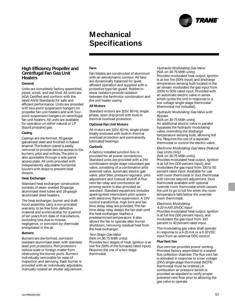
57UH-PRC002-EN
MechanicalSpecifications
High Efficiency Propeller andCentrifugal Fan Gas UnitHeaters
General
Units are completely factory assembled,piped, wired, and test fired. All units areAGA Certified and conform with thelatest ANSI Standards for safe andefficient performance. Units are providedwith two-point suspension hangers onpropeller fan unit heaters and with four-point suspension hangers on centrifugalfan unit heaters. All units are availablefor operation on either natural or LP(liquid propane) gas.
Casing
Casings are die-formed, 20-gaugegalvanized steel and finished in bakedenamel. The bottom panel is easilyremoved to provide service access to theburners, pilot and orifices. The pilot isalso accessible through a side panelaccess plate. All units provided withindependently adjustable horizontallouvers with stops to prevent totalclosure.
Heat Exchanger
Standard heat exchanger constructionconsists of seam welded 20-gaugealuminized steel tubes and 18-gaugealuminized steel headers.
The heat exchanger, burner and drafthood assembly carry a non-proratedwarranty to be free from defectivematerial and workmanship for a periodof ten years from date of manufacture,excluding loss due to misuse,negligence, or corrosion by chemicalsprecipitated in the air.
Burners
Burners are die-formed, corrosionresistant aluminized steel, with stainlesssteel port protectors. Port protectorsreduce scale or foreign matter fromobstructing the burner ports. Burnersindividually removable for ease ofinspection and servicing. Each burner isprovided with an individually adjustable,manually rotated air shutter adjustment.
Fans
Fan blades are constructed of aluminumwith an aerodynamic contour. All fansare dynamically balanced for quiet,efficient operation and supplied with aprotective type fan guard. Rubber-in-shear isolators provide isolationbetween the fan/motor combination andthe unit heater casing.
All Motors
Standard motors are 115V, 60 Hz, singlephase, open drip-proof with built-inthermal overload protection.
Optional Fan Unit Motors
All motors are 115V, 60 Hz, single phasetotally enclosed with built-in thermaloverload protection and permanentlylubricated bearings.
Controls
A factory installed junction box isprovided for all power connections.Standard units are provided with a 24Vcombination single stage redundant gasvalve, consisting of a combination pilotsolenoid valve, automatic electric gasvalve, pilot filter, pressure regulator, pilotadjustment and manual shutoff. A fluevent fan relay and combustion airproving switch is also provided asstandard. Standard equipment includesspark-ignited intermittent pilot systemwith electronic flame supervision. A 24Vcontrol transformer, high limit and fantime delay relay are provided. The fantime delay relay delays the fan start untilthe heat exchanger reaches apredetermined temperature. It alsoallows the fan to operate after burnershutdown, removing residual heat fromthe heat exchanger.
Two-Stage Gas Valve(N/A on 30-75 MBh units)Provides two stages of heat. Ignition is atlow fire (50% of the furnaces rated input).Requires the use of a two-stagethermostat.
Hydraulic Modulating Gas Valve(N/A on 30-75 MBh units)Provides modulated heat output. Ignitionis at low fire (50% input) and dischargetemperature sensing bulb located in theair stream modulates the gas input from100% to 50% rated input. Provided withan automatic electric valve in serieswhich cycles the unit in response to alow voltage single-stage thermostat(thermostat not included).
Hydraulic Modulating Gas Valve withBypass(N/A on 30-75 MBh units)An additional electric valve in parallelbypasses the hydraulic modulatingvalve, overriding the dischargetemperature sensing bulb, allowing fullfire. Requires the use of a separatethermostat to control the electric valve.
Electronic Modulating Gas Valve (NaturalGas Units Only)(N/A on 30-75 MBh units)Provides modulated heat output. Ignitionis at full fire (100 percent input), andmodulates the gas input from 100 to 50percent rated input. Available for usewith room thermostat or duct thermostatwith remote setpoint adjustment. Ductthermostat available with optionaloverride room thermostat which causesthe unit to go to full fire when the roomtemperature falls below the overrideroom thermostat.
Electronic Modulating4-20 mA/0-10VDC InputProvides modulated heat output. Ignitionis at full fire (100 percent input), andmodulates the gas input from 100percent to 40 percent rated input.
The modulating gas valve shall operatein response to a 4-20 mA or a 0-10 VDCinput from an external DDC control.
Flue Vent Fan
Flue vent fan provides power venting.Provided factory assembled to a sealedflue collection chamber. The flue vent fanis activated in response to a low voltage(24V) single-stage thermostat (NOTE:thermostat must be ordered.) Acombustion air pressure switch isprovided as standard to verify properpowered vent flow prior to allowing thegas valve to operate.

UH-PRC002-EN58
MechanicalSpecifications
Field Installed Accessories
High Gas Line Pressure Regulator(Natural gas units only)Reduces main gas line pressure to aminimum of seven inches W.C.. Pressureat the jobsite must be specified. Theregulator is selected to accommodatethat specific pressure.
Thermostats
Low voltage room thermostat, single-stage.
Low voltage room thermostat, single-stage with summer/winter switch.
Low voltage duct thermostat, single-stage.
Universal tamperproof guard for allroom thermostats.
Low voltage room thermostat, two-stage.
Low voltage duct thermostat, two-stage.
Room thermostat, electronic modulatingcontrol.
Duct thermostat, electronic modulatingcontrol.
Override room thermostat, for use withduct thermostat and electronicmodulating control.
Discharge NozzlesY Splitter30° Downward (100-400 MBh only)60° Downward (100-400 MBh only)90° Downward (100-400 MBh only)
Factory Installed Options
Heat Exchanger Options
Type 409 Stainless SteelHeat exchanger tubes and headers areseam welded 20-gauge Type 409stainless steel.
Type 321 Stainless SteelHeat exchanger tubes and headers areseam welded 20-gauge Type 321stainless steel. (Not available on 30, 45,60 and 75 MBh units.)
Additional Options
Type 409 Stainless Steel Burners(Not available on 30, 45, 60 and 75 MBhunits.)
Type 409 Stainless Steel Draft Diverter(Not available on 30, 45, 60 and 75 MBhunits.)
Orifices for elevations over 2,000 feet
Summer/Winter Switch
Vertical Louvers
Duct Discharge Flange(Centrifugal fan units only) Provided inlieu of louvers on units for use with fieldductwork.
OSHA Fan Guards – All Propeller UnitsOSHA fan guards are available as afactory installed or field installed option.

59UH-PRC002-EN
MechanicalSpecifications
Separated CombustionCentrifugal and Propeller FanGas Unit Heaters
General
Units are completely factory assembled,piped, wired, and test fired. All units areAGA Certified, 80 percent efficient andconform with the latest ANSI Standardsfor safe and efficient performance. Unitsare provided with two-point suspensionhangers on propeller fan unit heatersand with four-point suspension hangerson centrifugal fan unit heaters. Units areavailable for operation on either naturalor LP (propane) gas. Standard terms andconditions apply.
Casing
Casings are die-formed, 20-gaugegalvanized steel and finished in bakedenamel. The bottom panel is easilyremoved to provide service access to theburners, pilot and orifice. All unitsprovided with independently adjustablehorizontal louvers with stops to preventtotal closure.
Heat Exchanger
Standard heat exchanger constructionconsists of seam welded 20-gaugealuminized steel tubes and 18-gaugealuminized steel headers.
Burners
Burners are die-formed, corrosionresistant aluminized steel, with stainlesssteel port protectors. Port protectorsprevent scale or foreign matter fromobstructing the burner ports. Burnersindividually removable for ease ofinspection and servicing. Each burner isprovided with an individually adjustable,manually rotated air shutter adjustment.
Fans
Propeller fan blades are constructed ofaluminum with an aerodynamic contour.All fans are dynamically balanced forquiet, efficient operation and suppliedwith a protective type fan guard. Rubber-in-shear isolators provide isolationbetween the fan/motor combination andthe unit heater casing.
Centrifugal fan is belt driven withadjustable pitch motor sheave. Motorand fan are dynamically balanced forquiet operation.
Centrifugal Unit Motors
Standard motors are 115V, 60 Hz, singlephase, open drip-proof with built-inthermal overload protection. Optional230/60/1 motors are available on allunits. Optional 208, 230, 460/60/3 motorsare available on 125 through 400 MBhunits.
All Motors
All motors are 115V, 60 Hz, single-phaseopen drip-proof with built-in thermaloverload protection and permanentlylubricated bearings.
Controls
A factory installed junction box isprovided for all power connections.Standard units are provided with a 24Vcombination single-stage redundant gasvalve, consisting of a combination pilotsolenoid valve, automatic electric gasvalve, pilot filter, pressure regulator, pilotadjustment and manual shutoff. A fluevent fan relay and combustion airproving switch is also provided asstandard. Standard equipment includesspark-ignited intermittent pilot systemwith electronic flame supervision. A 24Vcontrol transformer, high limit and fantime delay relay are provided. The fantime delay relay delays the fan start untilthe heat exchanger reaches apredetermined temperature. It alsoallows the fan to operate after burnershutdown, removing residual heat fromthe heat exchanger.
Electronic Modulating4-20 mA/0-10VDC InputProvides modulated heat output. Ignitionis at full fire (100 percent input), andmodulates the gas input from 100percent to 40 percent rated input.
The modulating gas valve shall operatein response to a 4-20 mA or a 0-10 VDCinput from an external DDC control.
Flue Vent Fan
Flue vent fan provides power venting.Provided factory assembled to a sealedflue collection chamber. The flue vent fanis activated in response to a low voltage(24V) single-stage thermostat (NOTE: Thethermostat is not included with the gascontrol option). A combustion airpressure switch is provided as standardto verify proper powered vent flow priorto allowing the gas valve to operate.

UH-PRC002-EN60
MechanicalSpecifications
Factory Installed Options
Two-Stage Gas ValveProvides two stages of heat. Ignition is atlow fire (50 percent of the furnaces ratedinput). Requires the use of a two-stagethermostat.
Heat Exchanger Options
Type 409 Stainless SteelHeat exchanger tubes and headers areseam welded 20-gauge Type 409stainless steel.
Type 321 Stainless SteelHeat exchanger tubes and headers areseam welded 20-gauge Type 321stainless steel.
Additional Options
Type 409 Stainless Steel Burners
Type 409 Stainless Steel Draft Diverter
Totally Enclosed Motor
Orifices for elevations over 2000 feet
Summer/Winter Switch
Vertical Louvers
Duct Discharge Flange(Centrifugal fan units only) Provided inlieu of louvers on units for use with fieldductwork.
OSHA Fan GuardsOSHA fan guards are available as afactory installed or field installed option.
Field Installed Accessories
LP (Propane) to Natural Gas ConversionPackage
High Gas Line Pressure Regulator(Natural gas units only)Reduces main gas line pressure to aminimum of seven-inches W.C. Pressureat the jobsite must be specified. Theregulator is selected to accommodatethat specific pressure.
Thermostats
Low voltage room thermostat, single-stage.
Low voltage room thermostat, single-stage with summer/winter switch.
Low voltage duct thermostat, single-stage.
Low voltage room thermostat, two-stage.
Low voltage duct thermostat, two-stage.
Universal tamperproof guard for allroom thermostats.
Discharge NozzlesY Splitter30° Downward60° Downward90° Downward
Concentric Vent Terminals
Vertical Concentric Vent KitKit includes 5” cap with special attachednon-recirculation disc, special 8” capwith 5” hole and concentric vent box.
Horizontal Concentric Vent KitKit includes 5” cap with special attachednon-recirculation disc, inlet air screenand concentric vent box.

61UH-PRC002-EN
MechanicalSpecifications
Tubular Heat ExchangerIndoor Gas Unit
Unit is completely factory assembled,piped, wired and test fired. Unit is AGAand CGA certified, over 80 percentthermal (combustion) efficient. Thesepropeller type units are provided withaluminized tubular heat exchanger, in-shot burner, hot surface pilot ignition,individually adjustable and removablelouvers, 100 percent baked enamelfinish, 115/60/1 supply voltage,removable access door on size 30 to75 MBh, and hinged access control panelon 100 to 400 MBh, power vented,single-stage combination gas valve, two-stage available on 100 to 400 MBh, 24Vcontrol transformer and 115/60/1 volt fanmotor with internal overload protection.The size 30 to 90 are available in lowprofile design.
Residential Garage Certified
The GTNDR unit heaters are AGA andCGA certified for installations inresidential garages. With this certificationand the low profile design, these GTNDRmodels are ideal for residential garage,commercial and industrial installations.
Tubular Heat Exchanger
Heat exchanger construction consists of20-gauge aluminized steel. The tubulardesign provides maximum and uniformheat transfer. The low pressure dropenables heated air to be evenlydistributed. The curved, non-weldedserpentine design, experiences lessthermally induced stress making ithighly durable for longer service life.
Cabinet
The cabinet is constructed of 20-gaugecold rolled steel. All components areindividually electrostatically painted.
Hot Surface Pilot Ignition
This ignition is constructed of shockresistant ceramic composite hot surfaceelement. This system does not permitpilot gas to flow unless the hot surfaceelement is present and powered. The lowvoltage hot surface element lights thepilot quickly for fast heat delivery. Allwiring is 24V with no line voltage in theburner area.
Venting
The tubular design is AGA/CGA certifiedin accordance withCategories I and III ventingrequirements. Category I enables unitsto be vented vertically with either singleor double wall venting material.Category III allows for horizontal ventingutilizing single wall venting material.This venting flexibility makesinstallation easier and more costeffective.
Control Accessibility
All controls are easily accessible withignition and fan controls located in onecentrally located control panel. Theremovable door on size 30 to 75 MBhand the hinged access door on the 100400 MBh provide control isolation.
Motor –115V ODP
Motor is 115V, 60 Hz, single phase, opendrip-proof with built-in thermal overloadprotection.
Optional Feature
Motor — 115V totally enclosed.Motor is 115V, 60 Hz, single phase,totally enclosed with built-in thermaloverload protection.
Warranty
The heat exchanger, flue collector andburners are covered by a 10 yearwarranty from the date of manufacture.

UH-PRC002-EN62
MechanicalSpecifications
Propeller Fan Gas Unit Heater
Centrifugal Fan Gas UnitHeater
Indoor Gas Duct Furnace
General
Units are completely factory assembled,piped, wired and test fired. All units areAGA Certified and conform with thelatest ANSI Standards for safe andefficient performance. Units are providedwith two-point suspension hangers onpropeller fan unit heaters and with fourpoint suspension hangers on centrifugalfan unit heaters and duct furnaces. Allunits are available for operation on eithernatural or LP (propane) gas.
Casing
Casings are die-formed, 20-gaugegalvanized steel and finished in bakedenamel. The bottom panel is easilyremoved to provide service access to theburners, pilot and orifices. The pilot isalso accessible through a side panelaccess plate.
On duct furnaces the high limit switch isaccessible through a side panel access.
Duct discharge flanges for simpleductwork connection are provided.
All unit heaters are provided withindependently adjustable horizontallouvers with stops to prevent totalclosure.
Heat Exchanger
Standard heat exchanger constructionconsists of seam welded 20-gaugealuminized steel tubes and 18-gaugealuminized steel headers.
The heat exchanger, burner and drafthood assembly carry a non-proratedwarranty to be free from defectivematerial and workmanship for a periodof 10 years from date of manufacture,excluding loss due to misuse,negligence, or corrosion by chemicalsprecipitated in the air. (Not available onduct furnaces.)
Draft Diverter
Standard draft diverter construction iscorrosion resistant aluminized steel.
Burners
Burners are die-formed, corrosionresistant aluminized steel, with stainlesssteel port protectors. Port protectorsprevent scale or foreign matter fromobstructing the burner ports. Burners areindividually removable for ease ofinspection and servicing. Each burner isprovided with an individually adjustable,manually rotated air shutter adjustment.Air shutter adjustment is fixed on ductfurnaces when the side access burnerdrawer is supplied.
Fans
Propeller fan blades are constructed ofaluminum with an aerodynamic contour.All fans are dynamically balanced forquiet, efficient operation and suppliedwith a protective type fan guard. Rubber-in-shear isolators provide isolationbetween the fan/motor combination andthe unit heater casing.
Centrifugal fan is belt driven withadjustable pitch motor sheave. Fan isdynamically balanced for quietoperation.
Motors
Standard motors are 115V, 60 Hz, single-phase, open drip-proof with built-inthermal overload protection. Optional230/60/1 motors are available on allunits. Optional 208, 230, 460/60/3 motorsare available on 125 through 400 MBhunits.
Controls
A factory installed junction box isprovided for all power connections.Standard units are provided with a24-volt combination single-stageautomatic gas valve, including mainoperating valve and pilot safety shutoff,pressure regulator, manual main andpilot shutoff valve, and adjustable pilotvalve. Gas valve is suitable to amaximum inlet pressure of 0.5 psi (14-inch W.C.) on natural gas. A 24V controltransformer, a spill (blocked vent) switch,high limit and fan time delay relay(optional on duct furnaces) are provided.The fan time delay relay delays the fanstart until the heat exchanger reaches apredetermined temperature. It alsoallows the fan to operate after burnershutdown, removing residual heat fromthe heat exchanger.

63UH-PRC002-EN
MechanicalSpecifications
Factory Installed Options
Control OptionsHydraulic Modulating Gas ValveProvides modulated heat output. Ignitionis at low fire (50 percent input) anddischarge temperature sensing bulblocated in the air stream modulates thegas input from 50 percent to 100 percentrated input. Provided with an automaticelectric valve in series which cycles theunit in response to a low voltage single-stage thermostat (thermostat notincluded). (Not available on 30-75 MBhunits.)
Intermittent Pilot IgnitionSolid state ignition control system ignitesthe pilot by spark during each cycle ofoperation. When pilot flame is proven,main burner valve opens to allow gasflow to burners. Pilot and burners areextinguished during off cycle. Requiredon California units.
Two-Stage Gas Valve(Not available on 30-75 MBh units.)Provides two stages of heat. Ignition is atlow fire (50 percent of the furnace’s ratedinput). Requires the use of atwo-stage thermostat.
Hydraulic Modulating Gas Valve withBypass (N/A on 30-75 MBh units)An additional electric valve in parallelbypasses the hydraulic modulating valve,overriding the discharge temperaturesensing bulb, allowing full fire. Requiresthe use of a separate thermostat tocontrol the electric valve.
Electronic Modulating Gas Valve (NaturalGas Units Only) (N/A on 30-75 MBhunits)Provides modulated heat output. Ignitionis at full fire (100 percent input), andmodulates the gas input from 100 to 50percent rated input. Available for usewith room thermostat or duct thermostatwith remote setpoint adjustment. Ductthermostat available with optionaloverride room thermostat which causesthe unit to go to full fire when the roomtemperature falls below the overrideroom thermostat.
Electronic Modulating4-20 mA/0-10VDC InputProvides modulated heat output. Ignitionis at full fire (100 percent input), andmodulates the gas input from 100percent to 40 percent rated input.
The modulating gas valve shall operatein response to a 4-20 mA or a 0-10 VDCinput from an external DDC control.
Heat Exchanger Options
Type 409 Stainless SteelHeat exchanger tubes and headers areseam welded 20-gauge Type 409stainless steel.
Type 321 Stainless SteelHeat exchanger tubes and headers areseam welded 20-gauge Type 321stainless steel (100-400 MBh only).
Additional Options
Type 409 Stainless Steel Burners(Not available on 30-75 MBh units.)
Orifices for Elevations Over 2000 FeetType 409 Stainless Steel Draft Diverter(Not available on 30-75 MBh units.)
Summer/Winter Switch
Vertical Louvers
Horizontal Louvers (Duct furnace only)
Duct Discharge FlangeProvided in lieu of louvers on units foruse with field ductwork (Centrifugal unitsonly)
Totally Enclosed Motor
Side Access Burner Drawer (DuctFurnace Only)Allows entire burner drawer to slide outfrom the side of the unit for service orinspection.
Fan Time Delay Relay —(Duct FurnaceOnly)The fan time delay relay delays the fanstart until the heat exchanger reaches apredetermined temperature. It alsoallows the fan to operate after burnershutdown, removing the residual heatfrom the heat exchanger(Recommended on applications thatrequire intermittent fan.)
One-inch throwaway filters (Centrifugalwith enclosure only)
One-inch permanent filters (Centrifugalwith enclosure only)
Field Installed Accessories
Natural to LP (Propane) Gas ConversionPackage (Standing Pilot Only)
LP (Propane) to Natural Gas ConversionPackage
Flue Vent FanFlue vent fan provides power venting.Provided with all fixtures for fieldmounting and wiring, the flue vent fan isactivated in response to a single stagethermostat. A centrifugal switch in theflue vent in turn activates the automaticelectric gas valve.
High Gas Line Pressure RegulatorReduces main gas line pressure to aminimum of seven-inches W.C. Pressureat the jobsite must be specified. Theregulator is selected to accommodatethat specific pressure. (Natural gas unitsonly.)
Discharge Nozzles“Y” Splitter (100-400 MBh only)30° Downward (100-400 MBh only)60° Downward (100-400 MBh only)90° Downward (100-400 MBh only)
Drain Pan (Duct Furnace Only)Recommended for use with installationson the downstream side of a coolingcoil.
Thermostats
Low voltage room thermostat single-stage.
Low voltage room thermostat, single-stage with summer/winter switch.
Low voltage room thermostat,two-stage.
Universal tamperproof guard for allroom thermostats.
Low voltage duct thermostat, single-stage.
Low voltage duct thermostat,two-stage.
Room thermostat, electronic modulatingcontrol.
Duct thermostat, electronic modulatingcontrol.
Override room thermostat, for use withduct thermostat and electronicmodulating control.

UH-PRC002-EN64
MechanicalSpecifications
Separated Combustion DuctFurnaces
General
Units are completely factory assembled,piped, wired, and test fired. All units areAGA Certified, 80 percent efficient andconform with the latest ANSI Standardsfor safe and efficient performance. Unitsare provided with two-point suspensionhangers on propeller fan unit heatersand with four-point suspension hangerson centrifugal fan unit heaters. Units areavailable for operation on either naturalor LP (propane) gas. Standard terms andconditions apply.
Casing
Casings are die-formed, 20-gaugegalvanized steel and finished in bakedenamel. The bottom panel is easilyremoved to provide service access to theburners, pilot and orifice. All unitsprovided with independently adjustablehorizontal louvers with stops to preventtotal closure.
Heat Exchanger
Standard heat exchanger constructionconsists of seam welded 20-gaugealuminized steel tubes and 18-gaugealuminized steel headers.
Burners
Burners are die-formed, corrosionresistant aluminized steel, with stainlesssteel port protectors. Port protectorsprevent scale or foreign matter fromobstructing the burner ports. Burnersindividually removable for ease ofinspection and servicing. Each burner isprovided with an individually adjustable,manually rotated air shutter adjustment.
Controls
A factory installed junction box isprovided for all power connections.Standard units are provided with a 24Vcombination single-stage redundant gasvalve, consisting of a combination pilotsolenoid valve, automatic electric gasvalve, pilot filter, pressure regulator, pilotadjustment and manual shutoff. A fluevent fan relay and combustion airproving switch is also provided asstandard. Standard equipment includesspark-ignited intermittent pilot systemwith electronic flame supervision. A 24V
control transformer, high limit and fantime delay relay are provided. The fantime delay relay delays the fan start untilthe heat exchanger reaches apredetermined temperature. It alsoallows the fan to operate after burnershutdown, removing residual heat fromthe heat exchanger.
Electronic Modulating4-20 mA/0-10VDC InputProvides modulated heat output. Ignitionis at full fire (100 percent input), andmodulates the gas input from 100percent to 40 percent rated input.
The modulating gas valve shall operatein response to a 4-20 mA or a 0-10 VDCinput from an external DDC control.
Flue Vent Fan
Flue vent fan provides power venting.Provided factory assembled to a sealedflue collection chamber. The flue vent fanis activated in response to a low voltage(24V) single-stage thermostat (NOTE: Thethermostat is not included with the gascontrol option). A combustion airpressure switch is provided as standardto verify proper powered vent flow priorto allowing the gas valve to operate.
Factory Installed Options
Two-Stage Gas ValveProvides two stages of heat. Ignition is atlow fire (50 percent of the furnace’s ratedinput). Requires the use of a two-stagethermostat.
Heat Exchanger Options
Type 409 Stainless SteelHeat exchanger tubes and headers areseam welded 20-gauge Type 409stainless steel.
Type 321 Stainless SteelHeat exchanger tubes and headers areseam welded 20-gauge Type 321stainless steel.
Additional Options
Type 409 Stainless Steel Burners
Type 409 Stainless Steel Draft Diverter
Totally Enclosed Motor (Centrifugal fanunits only)
Orifices for elevations over 2000 feet
Summer/Winter Switch
Vertical Louvers
Duct Discharge Flange(Centrifugal fan units only) Provided inlieu of louvers on units for use with fieldductwork.
Field Installed Accessories
LP (Propane) to Natural Gas ConversionPackage
High Gas Line Pressure Regulator(Natural gas units only) Reduces maingas line pressure to a minimum ofseven-inches W.C. Pressure at the jobsitemust be specified. The regulator isselected to accommodate that specificpressure.
Thermostats
Low voltage room thermostat, single-stage.Low voltage room thermostat, single-stage with summer/winter switch.
Low voltage duct thermostat, single-stage.
Low voltage room thermostat, two-stage.
Low voltage duct thermostat, two-stage.
Universal tamperproof guard for allroom thermostats.
Discharge Nozzles
Y Splitter
30° Downward
60° Downward
90° Downward
Concentric Vent Terminals
Vertical Concentric Vent KitKit includes 5” cap with special attachednon-recirculation disc, special 8” capwith 5” hole and concentric vent box.
Horizontal Concentric Vent KitKit includes 5” cap with special attachednon-recirculation disc, inlet air screenand concentric vent box.

65UH-PRC002-EN
MechanicalSpecifications
High Efficiency Indoor Gas
Duct Furnaces
General
Units are completely factory assembled,piped, wired, and test fired. All units areAGA Certified and conform with thelatest ANSI Standards for safe andefficient performance. Units are providedwith four point suspension hangers, andare available for operation on eithernatural or LP (propane) gas.
Casing
Casings are die-formed, 20-gaugegalvanized steel and finished in bakedenamel. The bottom panel is easilyremoved to provide access to theburners, pilot and orifices. The pilot isalso accessible through a side panelaccess plate. The high limit switch isaccessible through a side panel access.Duct discharge flanges for simpleductwork connection are provided.
Heat Exchanger
Standard heat exchanger constructionconsists of seam welded 20-gaugealuminized steel tubes and 18-gaugealuminized steel headers.
Burners
Burners are die-formed, corrosionresistant aluminized steel, with stainlesssteel port protectors. Port protectorsprevent foreign matter from obstructingthe burner ports. Burners individuallyremovable for ease of inspection andservicing. Each burner is provided withan individually adjustable, manuallyrotated air shutter adjustment. Air shutteradjustment is fixed when side accessburner drawer is supplied.
Controls
A factory installed junction box isprovided for all power connections.Standards units are provided with a
24-volt combination single-stageredundant gas valve, consisting of acombination pilot solenoid valve,automatic electric gas valve, pilot filter,pressure regulator, pilot adjustment andmanual shutoff. A flue vent fan relay andcombustion air proving switch is alsoprovided as standard. Standardequipment includes spark-ignitedintermittent pilot system with electronicflame supervision. A 24V controltransformer and a high limit areprovided.
Flue Vent Fan
Flue vent fan is factory assembled to asealed flue collection chamber andprovides power venting. The flue ventfan is activated in response to a lowvoltage (24V) single-stage thermostat. Acombustion air pressure switch isprovided as standard to verify properpowered vent flow prior to allowing thegas valve to operate.
Control Options
Two-Stage Gas ValveProvides two stages of heat. Ignition is atlow fire (50 percent of the furnace’s ratedinput). Requires the use of a two-stagethermostat. (Thermostat not included.)
Hydraulic Modulating Gas ValveProvides modulated heat output. Ignitionis at low fire (50 percent input) anddischarge temperature sensing bulblocated in the airstream modulates thegas input from100 percent to 50 percent rated input.Provided with an automatic electric valvein series which cycles the unit inresponse to a low voltage single-stagethermostat. (Thermostat not included.)
Hydraulic Modulating Gas Valve withBypassAn additional electric valve in parallelbypasses the hydraulic modulatingvalve, overriding the dischargetemperature sensing bulb, allowing fullfire. Requires the use of a separatethermostat to control the electric valve.
Electronic Modulating Gas Valve (NaturalGas Units Only)Provides modulated heat output. Ignitionis at full fire (100 percent input), andmodulates the gas input from100 to 50 percent rated input. Availablefor use with room thermostat or ductthermostat with remote setpointadjustment. Duct thermostat availablewith optional override room thermostatwhich causes the unit to go to full firewhen the room temperature falls belowthe override room thermostat.
Electronic Modulating4-20 mA/0-10VDC InputProvides modulated heat output. Ignitionis at full fire (100 percent input), andmodulates the gas input from 100percent to 40 percent rated input.
The modulating gas valve shall operatein response to a 4-20 mA or a 0-10 VDCinput from an external DDC control.
Heat Exchanger Options
Type 409 Stainless SteelHeat exchanger tubes and headers areseam welded 20-gauge Type 409stainless steel
Type 321 Stainless SteelHeat exchanger tubes and headers areseam welded 20-gauge Type 321stainless steel
Additional Options
Type 409 Stainless Steel Burners
Orifices for Elevations over 2000 feet
Type 409 Stainless Steel Draft Diverter
Summer/Winter Switch
Horizontal Louvers
Horizontal and Vertical Louvers
Side Access Burner DrawerAllows entire burner drawer to slide outfrom the side of the unit for service orinspection.
Fan Time Delay RelayThe fan time delay relay delays the fanstart until the heat exchanger reaches apredetermined temperature. It alsoallows the fan to operate after burnershutdown, removing the residual heatfrom the heat exchanger.(Recommended on applications thatrequire intermittent fan)

UH-PRC002-EN66
MechanicalSpecifications
Horizontal Blower Assembly
General
Units are completely factory assembled,and have four-point suspension hangersand filter racks as standard.
Casing
Casings are 18-gauge galvanized steelwith baked enamel finish. Side panelsare removable for easy servicing andmotor maintenance. Duct flanges areprovided for simple ductworkconnection. Standard filters are one-inchpermanent washable type.
Motors
Factory mounted motors are open drip-proof, 115, 230/60/1 or 208, 230, 460/60/3with built-in thermal overload protection.
Fans
Centrifugal fan is belt driven withadjustable pitch motor sheave. Fan isdynamically balanced for quietoperation.
Field Installed Accessories
Natural to LP (Propane) Gas ConversionPackage (Standing Pilot Only)
LP (Propane) to Natural Gas ConversionPackage
High Gas Line Pressure RegulatorReduces main gas line pressure to aminimum of seven-inches W.C. Pressureat the jobsite must be specified. Theregulator is selected to accommodatethat specific pressure.
Discharge Nozzles“Y” Splitter30° Downward60° Downward90° Downward
Drain PanRecommended for use with installationson the downstream side of a coolingcoil.
Thermostats
Low voltage room thermostat, single-stage
Low voltage room thermostat, two-stage
Low voltage duct thermostat, single-stage
Low voltage duct thermostat, two-stage
Universal tamperproof guard for allroom thermostats
Low voltage room thermostat, single-stage with summer/winter switch
Room thermostat, electronic modulatingcontrol
Duct thermostat, electronic modulatingcontrol
Override room thermostat, for use withduct thermostat and electronicmodulating control.
Factory Installed Options
Insulation
Blower assembly and transition areinsulated with fire-resistant, odorless,mat-faced one-inch glass fiber material.
Floor Mounting Legs
Legs allow floor mounting of the blowerassembly.
Totally Enclosed Motor
Field Installed Accessories
Optional Filters(One-Inch Permanent Standard)
One-inch throwaway
One-inch permanent
TransitionWhen used with a duct furnace, a sheetmetal transition is supplied to connectthe blower assembly to the duct furnace.

67UH-PRC002-EN

The Trane CompanyAn American Standard Companywww.trane.com
Since The Trane Company has a policy of continuous product and product data improvement, it reserves theright to change design and specifications without notice.
Literature Order Number
File Number
Supersedes
Stocking Location
For more information contact your localdistributor (dealer), local district office, ore-mail us at [email protected]
UH-PRC002-EN
PL-UN-UH-000-PRC002-2-01
UH-PRC002-EN 6/00
Inland - LaCrosse


