Indoor Gas-Fired Make-Up Air Handlers Standard and High ...€¦ · Make-Up Air Handlers Standard...
88
MUA-D-3 Indoor Gas-Fired Make-Up Air Handlers Standard and High Efficiency Packaged Unit for Heating, Cooling, Ventilating and Make-Up Air Applications June 2003
Transcript of Indoor Gas-Fired Make-Up Air Handlers Standard and High ...€¦ · Make-Up Air Handlers Standard...

MUA-D-3
Indoor Gas-FiredMake-Up Air HandlersStandard and High Efficiency
Packaged Unit for Heating, Cooling,Ventilating and Make-Up Air Applications
June 2003

2©2003 American Standard Inc.
FeaturesandBenefits
GeneralThe Trane indoor make-up air handlerproduct line is a packaged air, heatingand cooling system, suitable forheating, cooling, ventilating andmake-up air applications. These unitsare designed for indoor use only. Unitsizes range from 900 to 9,800 cfm(0.4-4.6 cu m/s) with 1/2 to 15 hp motorcapabilities. These units are availablewith inputs from 100,000 Btu/h to1,200,000 Btu/h (29.3 to 351.4 kW).
Duct furnaces are AGA and CGAcertified for safety and performancewith a range of 100,000 Btu/h input to400,000 Btu/h (29.3 to 117.1 kW) inputper duct furnace. The units can beordered as heating only, heating withevaporative cooling or packagedheating and cooling systems.
The mechanical configuration isdetermined by selecting one of the fourstandard arrangements. Arrangementsare divided into two classifications –standard and high cfm blower types.
The standard blower unit consists of ablower cabinet that houses dampers,filters and blower in one cabinet. Anoptional evaporative cooling unit isavailable on units up to 800 MBh(234.3 kW). Trane recommends the useof 409 stainless steel wheneverevaporative cooling is installedupstream of a duct furnace section(s).
The high cfm blower unit utilizes aseparate damper/filter cabinet with a“V” bank filter arrangement, a blowercabinet and up to three duct furnaces(1200 MBh) (351.4 kW). An optionalcooling coil cabinet is offered on unitsup to 800 MBh. Trane recommends theuse of 409 stainless steel whenever acoil is used upstream of a furnacesection(s). Both standard and high cfmblower arrangements may also includeoutside air and/or return air.
All units are completely packaged, rail-mounted, wired, piped and test fired toassure a smooth installation and easystart-up.
All furnaces have optional left or righthand access. The maximum dischargeair temperature for all duct furnaces is150 F (66 C).
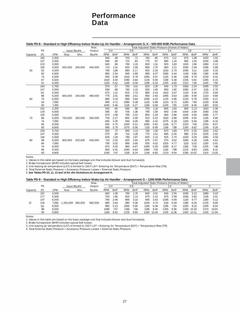
Control OptionsIn addition to a versatile offering ofmechanical features, this new unit alsooffers a wide variety of factory installedcontrol options. Control componentsare located in the main electricalcabinet. The main electrical cabinet islocated out of the airstream as part ofthe blower transition, between theblower cabinet and the first furnace forboth standard and high cfm units. Thestandard electrical control schemeconsists of a solid-state fan time delay,two pre-wired relay sockets for fan onand damper open functions mountedon the unit’s main connection board, asolid stage gas ignition system androom or duct thermostats. The units arealso equipped with a blower doorsafety interlock, a 24 VAC circuitbreaker, a high temperature limit switchin each furnace section and a reverseairflow switch located in the blowercabinet as standard equipment.
Gas control options range from singlestage to six stages of fire, mechanicalor electronic modulation and directdigital control (DDC). Air controloptions offer a similar range of controlfeatures from manual dampers tomodulating dampers that may includemixed air, dry bulb, pressure sensing,enthalpy control, DDC interface orASHRAE cycle control arrangements.
Units are available in a standard orhigh efficiency line. The high efficiencyline features an integral flue vent fanand sealed flue collector for improvedcombustion. It reduces airrequirements and wind effects on thesystem’s efficiency. Intermittent pilotignition reduces pilot gas losses andthe flue vent fan allows for horizontalventing through side walls.

3
Features and Benefits 2
Model Number Description 4
Unit Configurations 6
General Data 10
Application Considerations 12
Selection Procedure 14
Performance Adjustment Factors 19
Performance Data 20
Electrical Data 37
Controls 38
Dimensional Data 41
Weights 66
Options 68
Features Summary 71
Mechanical Specifications 72
Contents
Features and Benefits• AGA and CGA certified duct furnaces• FM (Factory Mutual) Compliant• Heating capacities from 100 MBh to
1200 MBh (29.3 kW- 351.4 kW)• Gravity and power vented furnaces• Cfm ranges from 900 to 9800 cfm
(0.4-4.6 cu. m/s)• Motor sizes up to 15 horsepower• ODP motors with high efficiency and
totally enclosed options• Left hand or right hand service access• Draw-thru coil cabinet with stainless
steel drain pan• Evaporative cooling with standard 8 or
optional 12” media (203 or 305 mm)• Standard 18-gauge cabinets
• Standard 20-gauge aluminized steelheat exchanger
• Standard one-inch washable filters• Standard single stage combination gas
valve• Standard high temperature limit (each
furnace)• Standard blower door safety interlock
switch• Standard reverse airflow safety switch• Standard 24-volt circuit breaker• Standard printed circuit main
connection board• Wiring harnesses with stamped wire
numbers• Solid stage automatic pilot ignition
control• Solid-state fan time delay• Over 40 standard gas and air control
packages

4
Digit 1 — Gas Heating EquipmentG = Gas
Digit 2 — Unit TypeS = Indoor Make-Up Air HandlerG = High Efficiency Indoor Make-Up Air
HandlerD = Indoor Duct FurnaceL = High Efficiency Indoor Duct Furnace
Digit 3 — Furnace TypeA = Standard Temp Rise (30-80 F) LHB = Standard Temp Rise (30-80 F) RHS = Special Furnace TypeNote: LH = Left Hand RH = Right Hand
Digit 4 — Development SequenceA = First Generation
Digits 5 and 6 — Input CapacitySingle Furnace10 = 100 MBh Input15 = 150 MBh Input20 = 200 MBh Input25 = 250 MBh Input30 = 300 MBh Input35 = 350 MBh Input40 = 400 MBh InputDouble Furnace50 = 500 MBh Input60 = 600 MBh Input70 = 700 MBh Input80 = 800 MBh InputTriple Furnace12 = 1200 MBh InputSS = Special unit
Digit 7 — Venting TypeG = Gravity Venting (All GS Units)P = Power Venting (All GG Units)S = Special Venting
Digit 8 — Main Power SupplyA = 115/60/1B = 208/60/1C = 230/60/1D = 208/60/3E = 230/60/3F = 460/60/3G = 575/60/3S = Special Main Power Supply
Digit 9 — Gas Control Option(Intermittent Pilot Ignition)
A = Single-StageB = Two-StageC = Hydraulic Modulating (60-100)D = Hydraulic Modulating (75-200)E = Hydraulic Modulating w/Bypass and
limit (60-100)F = Hydraulic Modulating w/Bypass
(75-200)G = Electronic Modulating w/Room T-StatH = Electronic Modulating w/Duct T-StatJ = Electronic Modulating w/Duct T-Stat
and Override Room ThermostatK = Electronic Modulating w/External
4-20 mA Input (Furnace 1)L = Electronic Modulating w/External
4-20 mA Input (All furnaces)M= Electronic Modulating w/External
0-10 VDC Input (Furnace 1)N = Electronic Modulating w/External
0-10 VDC Input (All furnaces)P = VAV Control Two-StageR = VAV Control Three-StageT = VAV Control Four-StageU = S-350 2-Stage Modular Electronic
Control SystemW= S-350 3-Stage Modular Electronic
Control SystemX = S-350 4-Stage Modular Electronic
Control SystemY = S-350 6-Stage Modular Electronic
Control SystemS = Special Gas Control
Digit 10, 11 — Design SequenceD0 = Design Sequence
Digit 12 — Fuel TypeN = Natural GasP = LP Gas (Propane)L = Natural Gas with 100% LockoutS = Special Fuel type
Digit 13 — Heat Exchanger Material1 = Aluminized Steel2 = #409 Stainless Steel (First Furnace Only)3 = #409 Stainless Steel (All Furnace
Sections)4 = #321 Stainless Steel (First Furnace Only)5 = #321 Stainless Steel (All Furnace
Sections)6 = #409 Stainless Steel Package
(First Furnace Only)7 = #409 Stainless Steel Package
(All Furnace Sections)8 = #321 Stainless Steel Package
(First Furnace Only)9 = #321 Stainless Steel Package
(All Furnace Sections)S = Special Heat Exchanger Package
Digit 14 — Indoor ArrangementsA = Indoor Duct FurnaceB = Blower (Standard)D = Blower (Standard) Evaporative CoolerG = Blower (High CFM)K = Blower (High CFM) /CoolingS = Special Rooftop Arrangement
Digit 15 — Indoor Heating Unit MotorSelection
0 = No Motor (Duct Furnace)A = 1/2 HP w/ContactorB = 3/4 HP w/ContactorC = 1 HP w/ContactorD = 1 1/2 HP w/ContactorE = 2 HP w/ContactorF = 3 HP w/ContactorG = 5 HP w/ContactorH = 1/2 HP w/Magnetic StarterJ = 3/4 HP w/Magnetic StarterK = 1 HP w/Magnetic StarterL = 1 1/2 HP w/Magnetic StarterN = 2 HP w/Magnetic StarterP = 3 HP w/Magnetic StarterQ = 5 HP w/Magnetic StarterR = 7 1/2 HP w/Magnetic StarterT = 10 HP w/Magnetic StarterU = 15 HP w/Magnetic StarterS = Special Motor
ModelNumberDescription
G S A A 40 G D C D0 N 2 B Q 1 0 1 A 0 +
1 2 3 4 5,6 7 8 9 10,11 12 13 14 15 16 17 18 19 20 21

5
ModelNumberDescription
Digit 16 — Motor Speed0 = No Motor (Duct Furnace)1 = Single Speed ODP 1800 RPM2 = Single Speed TEFC 1800 RPM3 = Single Speed High Efficiency ODP
1800 RPM4 = Single Speed High Efficiency TEFC
1800 RPM5 = 2S1W ODP 1800/900 RPM6 = 2S2W ODP 1800/1200 RPMS = Special Motor Speed and Starter
Digit 17 — Coil Options0 = No cooling Coil selectionA = DX Coil, 4-Row, Single CircuitB = DX Coil, 4-Row, Dual CircuitC = DX Coil, 6-Row, Single CircuitD = DX Coil, 6-Row, Dual CircuitE = Chilled Water Coil, 4-Row,G = Chilled Water Coil, 6-Row,S = Special Coil
Digit 18 — Air Inlet Configuration0 = None (Indoor Duct Furnace)1 = Outside Air (OA) Horizontal Inlet3 = Return Air (RA) Bottom Inlet4 = Outside and Return Air (OA/RA)S = Special Air Inlet Configuration
Digit 19 — Air Control andDamper Arrangement
0 = NoneA = Outside Air 2 Pos. Motor/SRB = Return Air 2 Pos. Motor/SRC = OA/RA 2 Pos SRE = OA/RA Mod Mtr w/Mixed Air Control/
Min Pot/SRH = OA/RA Mod Mtr w/Mixed Air Control/
SRK = OA/RA Mod Mtr w/Min Pot/SRM = OA/RA Mod Mtr w/Dry Bulb/Mixed Air
Control/Min Pot/SRN = OA/RA Mod Mtr w/Enthalpy Controlled
Economizer/SRP = OA/RA Mod Mtr w/Space Pressure
ControllerR = OA/RA Mod Mtr w/S-350 P
Proportional Mixed Air Control/SRU = OA/RA Mtr. w/External 0-10 VDC and
4-20 mA Analog Input/SR(External Input)
W= ASHRAE Cycle I (OA/RA 2 Pos.w/Warm-up Stat/SR
X = ASHRAE Cycle II (OA/RA Modw/Warm-up Stat/Mixed Air/min pot/SR
Y = ASHRAE Cycle III (OA/RA Mod.w/Warm-up Stat/Mixed Air/SR
Z = Manual DampersS = Special Air Control and
Damper Arrangement
Digit 200 = Non-California Shipment1 = California Shipment
Digit 21 — Miscellaneous OptionsA = Orifices for Elevation Above 2000 Feet
(Specify Elevation)B = 12” Evaporative Media (Celdek)D = Horizontal ReturnE = Interlock Relay – 24V Coil DPDT 10AF = FreezestatG = Fan Time Delay (Indoor Duct Furnace)H = Return Air FirestatJ = Supply Air FirestatK = Manual Blower SwitchL = 409 Stainless Steel Furnace Drip PanM = Double Wall ConstructionP = Low Leak DampersQ = Clogged Filter SwitchR = High/Low Gas Pressure Limit SwitchesT = Status Indicator Lamps (Elec Cabinet)V = Manual Reset High Limit SwitchW= Interlock Relay —24/115V Coil SPDT
10AX = Interlock Relay —24/115-230V Coil
DPDT 10AY = Ambient LockoutZ = 8” Evaporative Media (Glasdek)1 = 12” Evaporative Media (Glasdek)2 = Hinged Service Access Doors

6
Unit Type Standard Features
Arrangement A - Natural or LP (Propane Gas)Indoor Gas Duct Furnace - Single Stage 24 Volt Gas Valve
- Intermittent Pilot Ignition- Orificed for Operation Up to 2000' Above Sea Level- Aluminized Steel Heat Exchanger- 24 Volt High Temperature Safety Circuit- 24 Volt Control Circuitry- Blow-thru Applications Only
Arrangement B - Natural or LP (Propane Gas)Indoor Heating Unit with Standard Blower - Single Stage 24 Volt Gas Valve
- Intermittent Pilot Ignition- Orificed for Operation Up to 2000' Above Sea Level- Aluminized Steel Heat Exchanger- 24 Volt High Temperature Safety Circuit- Terminal Block Wiring, Single Point Connection- Quick Opening Access Doors (Blower Section)- Single, Forward Curved Blower- Insulated Blower/Filter/Damper Cabinet- 1” Permanent Filters- Fan Time Delay Relay- Electrical Cabinet Isolated from the Airstream- 24 Volt Control Circuitry- Low Voltage Circuit Breaker- Blower Door Interlock Switch with Service Override
Arrangement D Same as Arrangement B withIndoor Heating Unit with Standard Blower - Evaporative Coolerand Evaporative Cooler - High Efficiency 8“ Media
- Self Cleaning Design- Sealed Pump Motor with Float Valve- 24 Volt Control Circuitry- Heavy Duty Stainless Steel Water Tank- Easy Access Intake Filter and PVC Distribution Tubes
UnitConfigurations
Indoor Make-Up Air HandlerGravity Vented

7
Unit Type Standard Features
Arrangement G - Natural or LP (Propane Gas)Indoor Heating Unit with High Cfm Blower - Single Stage 24 Volt Gas Valve
- Intermittent Pilot Ignition- Orificed for Operation Up to 2000' Above Sea Level- Aluminized Steel Heat Exchanger- Electrical Cabinet Isolated from the Airstream- 24 Volt High Temperature Safety Circuit- Terminal Block Wiring, Single Point Connection- Quick Opening Access Doors (Blower Section)- 1 Permanent Filters- Fan Time Delay Relay- Standard V-bank Filter and Damper Cabinet- Insulated Filter/Damper and Blower Cabinet- Single Forward Curved Blower- 24 Volt Control Circuitry- Low Voltage Circuit Breaker- Blower Door Interlock Switch with Service Override
Arrangement K Same as Arrangement G withIndoor Heating Unit with High Cfm Blower - Coil Sectionand Cooling Coil Section - Mounting for 4 to 6 Row Coils – Single or Dual Circuit
- Stainless Steel Drain Pan with 3/4” Tapped Outlets
UnitConfigurations
Indoor Make-Up Air HandlerGravity Vented
Motors/air inlet configuration/air control and damper arrangement must be selected and added to the list price of each unit.
NOTES:1. Arrangements are shown with the maximum number of furnaces available.2. Legend is as follows:
B/F/D - Standard Blower/Filter/DamperSP - Supply PlenumEV - Evaporative CoolerF/D - Filter/DamperB - High Cfm BlowerCC - Cooling Coil
3. Horizontal outside air over return air. Specify air inlet Configuration 4 and then select miscellaneous Option D for horizontal return.
Air Inlet Configuration
1 3 4 See Note 3 Above

8
Unit Type Standard Features
Arrangement A - Natural or LP (Propane Gas)High Efficiency Indoor Gas Duct Furnace - Single Stage 24 Volt Gas Valve
- Intermittent Pilot Ignition- Orificed for Operation Up to 2000' Above Sea Level- Aluminized Steel Heat Exchanger- 24 Volt High Temperature Safety Circuit- 24 Volt Control Circuitry- Factory Installed Flue Vent Fan- Sealed Draft Diverter- Blow-thru Applications Only
Arrangement B - Natural or LP (Propane Gas)High Efficiency Indoor Heating Unit - Single Stage 24 Volt Gas Valvewith Standard Blower - Intermittent Pilot Ignition
- Orificed for Operation Up to 2000' Above Sea Level- Aluminized Steel Heat Exchanger- 24 Volt High Temperature Safety Circuit- Terminal Block Wiring, Single Point Connection- Quick Opening Access Doors (Blower Section)- Single, Forward Curved Blower- Insulated Blower/Filter/Damper Cabinet- 1” Permanent Filters- Fan Time Delay Relay- Electrical Cabinet Isolated from the Airstream- 24 Volt Control Circuitry- Low Voltage Circuit Breaker- Blower Door Interlock Switch with Service Override- Factory Installed Flue Vent Fan - Sealed Draft Diverter
Arrangement D Same as Arrangement B withHigh Efficiency Indoor Heating Unit - Evaporative Coolerwith Standard Blower and Evaporative Cooler - High Efficiency 8“ Media
- Self Cleaning Design- Sealed Pump Motor with Float Valve- 24 Volt Control Circuitry- Heavy Duty Stainless Steel Water Tank- Easy Access Intake Filter and PVC Distribution Tubes
UnitConfigurations
High Efficiency Indoor Make-Up Air HandlerPower Vented

9
Unit Type Standard Features
Arrangement G - Natural or LP (Propane Gas)High Efficiency Indoor Heating Unit - Single Stage 24 Volt Gas Valvewith High Cfm Blower - Intermittent Pilot Ignition
- Orificed for Operation Up to 2000' Above Sea Level- Aluminized Steel Heat Exchanger- Electrical Cabinet Insulated from the Airstream- 24 Volt High Temperature Safety Circuit- Terminal Block Wiring, Single Point Connection- Quick Opening Access Doors (Blower Section)- 1 Permanent Filters- Fan Time Delay Relay- Standard V-bank Filter and Damper Cabinet- Insulated Filter/Damper and Blower Cabinet- Single Forward Curved Blower- 24 Volt Control Circuitry- Low Voltage Circuit Breaker- Blower Door Interlock Switch with Service Override- Factory Installed Flue Vent Fan- Sealed Draft Diverter
Arrangement K Same as Arrangement G withIndoor Heating Unit with High Cfm Blower - Coil Sectionand Cooling Coil Section - Mounting for 4 to 6 Row Coils – Single or Dual Circuit
- Stainless Steel Drain Pan with 3/4” Tapped Outlet
UnitConfigurations
High Efficiency Indoor Make-Up Air HandlerPower Vented
Motors/air inlet configuration/air control and damper arrangement must be selected and added to the list price of each unit.
NOTES:1. Arrangements are shown with the maximum number of furnaces available.2. Legend is as follows:
B/F/D - Standard Blower/Filter/DamperSP - Supply PlenumEV - Evaporative CoolerF/D - Filter/DamperB - High Cfm BlowerCC - Cooling Coil
3. Horizontal outside air over return air. Specify air inlet Configuration 4 and then select miscellaneous Option D for horizontal return.
Air Inlet Configuration
1 3 4 See Note 3 Above

10
Furnace Type A, B Furnace Type A, B Furnace Type A, BTemperature Rise 30 F-80 F Temperature Rise 60 F-160 F Temperature Rise 90 F-180 F
Standard Blower Capacity 10-40 Capacity 60-80
Arrangements B 10 - 900-2,400 CFM, 1/2-3 HP 50 - 2,300-5,200 CFM, 1/2-5 HP15 - 1,400-3,600 CFM, 1/2-5 HP 60 - 2,700-6,000 CFM, 3/4-5 HP20 - 1,800-4,900 CFM, 1/2-5 HP 70 - 3,200-7,500 CFM, 1/2-5 HP N/A25 - 2,300-5,500 CFM, 1/2-5 HP 80 - 3,700-7,500 CFM, 3/4-5 HP30 - 2,700-6,500 CFM, 3/4-5 HP35 - 3,200-8,500 CFM, 3/4-5 HP 40 - 3,700-8,500 CFM, 3/4-5 HP
ESP .1-2” in WC ESP .1-2” in WCStandard Blower W/Evap. Capacity 10-40 Capacity 60-80
Arrangements D 10 - 900-2,400 CFM, 1/2-3 HP 50 - 2,300-5,200 CFM, 1/2-5 HP15 - 1,400-3,600 CFM, 1/2-5 HP 60 - 2,700-6,000 CFM, 3/4-5 HP20 - 1,800-4,900 CFM, 1/2-5 HP 70 - 3,200-7,500 CFM, 1/2-5 HP N/A25 - 2,300-5,500 CFM, 1/2-5 HP 80 - 3,700-7,500 CFM, 3/4-5 HP30 - 2,700-6,500 CFM, 3/4-5 HP35 - 3,200-8,500 CFM, 3/4-5 HP40 - 3,700-8,500 CFM, 3/4-5 HP
ESP .1-2” in WC ESP .1-2” in WCHigh CFM Blower Capacity 20-40 Capacity 60-80 Capacity 12Arrangements G 20 - 1,800-4,900 CFM, 1/2-5 HP 50 - 2,300-6,000 CFM, 1/2-10 HP 12 - 4,500-9,800 CFM, 1-15 HP
25 - 2,300-5,500 CFM, 1/2-7 1/2 HP 60 - 2,700-7,400 CFM, 1/2-10 HP30 - 2,700-7,400 CFM, 1/2-7 1/2 HP 70 - 3,200-8,600 CFM, 1/2-10 HP35 - 3,200-8,600 CFM, 1/2-10 HP 80 - 3,700-9,800 CFM, 3/4-15 HP40 - 3,700-9,800 CFM, 1/2-10 HP
ESP .1-2” in WC ESP .1-2” in WC ESP .1-2” in WCHigh CFM Blower W/Cooling Capacity 10-40 Capacity 60-80
Arrangements K* DX Coil 10 - 1,600-2,400 CFM, 1/2-5 HP 50 - 2,500-4,400 CFM, 1-5 HP 15 - 1,600-3,000 CFM, 1/2-5 HP 60 - 2,800-5,800 CFM, 3/4-7 1/2 HP20 - 2,100-4,400 CFM, 1/2-5 HP 70 - 3,200-5,800 CFM, 3/4-7 1/2 HP N/A25 - 2,500-4,400 CFM, 1/2-5 HP 80 - 3,700-6,500 CFM, 3/4-7 1/2 HP30 - 2,800-5,800 CFM, 3/4-7 1/2 HP35 - 3,200-5,800 CFM, 3/4-7 1/2 HP40 - 3,700-6,800 CFM, 3/4-7 1/2 HP
ESP .1-2” in WC ESP .1-2” in WCHigh CFM Blower W/Cooling Capacity 10-40 Capacity 60-80
Arrangements K* Chilled Water Coil 10 - 960-2,400 CFM, 1/2-5 HP 50 - 2,300-4,300 CFM, 1/2-5 HP15 - 1,400-2,900 CFM, 1/2-5 HP 60 - 2,700-5,700 CFM, 3/4-7 1/2 HP20 - 1,800-4,300 CFM, 1/2-5 HP 70 - 3,200-5,700 CFM, 3/4-7 1/2 HP N/A25 - 2,300-4,300 CFM, 1/2-5 HP 80 - 3,700-6,300 CFM, 3/4-7 1/2 HP30 - 2,700-5,700 CFM, 1/2-7 1/2 HP35 - 3,200-5,700 CFM, 3/4-7 1/2 HP40 - 3,700-6,300 CFM, 3/4-7 1/2 HP
ESP .1-2” in WC ESP .1-2” in WC
*The maximum CFM for Arrangements K is 6,500. A two-speed motor may be utilized for non-cooling air flow up to 9,800 cfm.
GeneralData
Indoor Makeup Air Arrangement Reference

11
Table G-1 — Filter DataRooftop Unit Size
Arrangement 10,15 20,25,50 30,35,60,70 40,80,12B-D (4)16 x 20 (4)20 x 20 (4)16 x 20 (6)20 x 20
(2)20 x 20G-K (8)16 x 20 (8)20 x 20 (8)16 x 20 (12)20 x 20
(4)20 x 20
Table G-2 — Metric Conversion TableUnless otherwise specified, the following conversions may be used for calculating SI unit measurements:1 cubic foot= 0.028 m3 1 inch water column = 0.029 kPa1 foot = 0.0305 m 1 gallon = 3.785 L1 inch = 25.4 mm 1,000 Btu/Cu. Ft. = 37.5 MJ/m31 psig = 6.894 kPa 1 liter/second = CFM x 0.4721 pound = 0.453 kg 1 meter/second = FPM ÷ 196.81,000 Btu per hour = 0.293 kW
GeneralData

12
ApplicationConsiderations
Gas Heating ValueThe majority of gas heating units areinstalled in applications where naturalgas is readily available. In areas wherenatural gas is not available, Trane unitsmay be ordered directly from thefactory for use on LP (propane) gas.
Gas heat content varies by fuel typeand location. The standard grossheating value for natural gas is 1,000Btuh per cubic foot; for propane it is2,500 Btuh per cubic foot. Significantvariations from these standard valuesshould be taken into account inequipment selections. To account forvariations in the gross heating value ofthe fuel, adjust the total heat inputrequired and select the unit on the basisof the adjusted load using the followingformula:
Adjusted load = Calculated load xStandard gross heat value (Btuh/cu ft)Actual gross heat value (Btuh/cu ft)
Low Temperature RiseTrane recommends against the setup ofa unit which will result in a temperaturerise of less than 20 F. With such lowtemperature rises, the flue gasespassing through the heat exchanger arecooled to condensate before reachingthe flue outlet. This condensate iscorrosive and will result in shortenedheat exchanger life.
Air DensityCatalog performance data is based onelevations up to 2,000 feet (610 m)above sea level. Above 2,000 feet (610m), the unit’s heating capacity must bederated four percent for each 1,000 feet(305 m) above sea level and specialorifice selections are required. TablePAF-1 contains correction factors thatcan be applied to the unit’s catalogedheating capacity, fan rpm, and fan bhpto obtain actual values for elevationsabove 2,000 feet (610 m).
Corrosive AtmospheresCorrosion of heat exchangers and draftdiverters have two basic variables —moisture (condensation) and sulfur.These two ingredients form to makesulfuric acid in the combustion process.Condensation occurs commonly inmake-up air systems, using largeamounts of fresh air, when airtemperatures entering the heatexchanger drop to 40 F or below. Thisreaction can also occur in recirculatingsystems where some quantity ofoutside air is introduced upstreamof the exchanger. The sulfur will alwaysbe present as an integral component ofthe gas. The resulting concentration ofthe acid is governed by the amount ofsulfur in the gas. This concentrationvaries from gas to gas and geographicallywithin the same type of gas.
Beyond sulfuric acid corrosion, there isthe area of chlorinated or halogenatedhydrocarbon vapor corrosion. This typeof corrosion occurs when substancesare mixed with combustion air that willcause the formation of hydrochloric orhydrofluoric acid when burned. Thesebasic substances are found indegreasers, dry cleaning solvents,glues, cements, paint removers andaerosol propellants. Specific chemicalsincluded in this group aretrichloroethylene, perchloroethylene,carbon tetrachloride, methylenechloride, methyl chloroform andrefrigerants 11, 12, 21, 22 and 114.
If sufficient ppm content of thesecorrosives is present, none of thecommon heat exchanger materials willhold up. The dilemma becomes whetherto place the gas heating equipmentoutside of the area to be conditioned oruse equipment in the space which doesnot burn a fuel such as gas (i.e., electricor hydronic).
Units should not be installed in areaswith corrosive or inflammableatmospheres. Locations containingsolvents or chlorinated hydrocarbonswill produce corrosive acids whencoming in contact with burner flames.This reaction will greatly reduce the lifeof the heat exchanger and may voidthe warranty. For added protectionagainst heat exchanger corrosion,optional 409 and 321 stainless steelconstruction is available.
On units using outside air, withentering air temperature below 40 F,condensation of flue gas in the heatexchanger is possible. In these cases,stainless steel heat exchangers arerecommended. An optional 409 or 321stainless steel heat exchanger isrecommended whenever there is anevaporative cooler or cooling coilupstream of the furnace section(s).
Careful review of the job applicationwith respect to use, probablecontaminants within a conditionedspace and the amount of fresh air to bebrought in will help to make the properselection of heat exchanger material.This review will help to eliminateproblems before they begin.

13
ApplicationConsiderations
FM and IRI RequirementsIRI, which stands for Industrial RiskInsurers, and FM, which stands forFactory Mutual, are both basicallyinsurance companies which insurecommercial/industrial firms against avariety of losses. Both publishrequirements which must be met bycertain equipment operating in thefacilities they are preparing to insure.
Listed below is our interpretation of therequirements of both insurerspertaining to heating units only to theextent of features/controls required byIRI and/or FM. There are a number ofadditional requirements which pertainto electrical service, details ofinstallation, etc., and we urge you toobtain copies of the publicationspertaining to these details if you areinvolved in a job where IRI or FMadherence has been indicated. Therequirements detailed herein are ourinterpretations of the latest publicationsin our possession and we mustdisclaim any responsibility for errorsdue to our interpretation and/or lack ofany updated revision of thesestandards. Our intent is to provide youwith an understanding of theapplication of these standards and howwe believe our indirect-fired gasheating equipment applies.
IRI Requirements
1All input sizes require 100 percentshutoff. This requires that any naturalgas unit, equipped with intermittentpilot ignition, must employ a “lock-out”type ignition system which will shut offpilot gas if the pilot fails to light at anytime. This system is required by AGAon LP gas units as standard equipment.However, for natural gas units, you willneed to specify fuel type “L” NaturalGas with 100 percent lockout.2All units require AGA certification or ULlisted controls. Our units are AGAcertified and meet this requirement.3Models with inputs of 150,000 to400,000 Btuh (43.9-117.1 kW) requiremechanical exhaust and a safetyinterlock. For our units this means apower vented unit.
FM Requirements
1All units must be AGA certified or ULlisted. Our units are AGA certified.2The high limit control must be in acircuit, the voltage of which does notexceed 120 VAC. All of our high limitswould meet this requirement.
The specific requirement for an “IRI orFM gas train,” while it applies to directand indirect-fired gas heatingequipment as well as oil-fired, comesinto play only with units having aninput in excess of 400,000 Btuh (117.1kW). This may be one of the reasonswhy the majority of gas heatingequipment manufacturers (indirect-fired) limit their largest individualfurnace to 400,000 Btuh (117.1 kW).
Minimum/Maximum GasInlet PressuresGas valves are suitable to a maximuminlet pressure of 0.5 psi (14 inches watercolumn) (3.5 kPa) on natural gas. If themain gas supply pressure is greaterthan 14 inches WC (3.5 kPa), a stepdown pressure regulator must be fieldinstalled ahead of the gas valve.Minimum inlet pressure for natural gasunits is 61/2 inches WC (1.6 kPa).
For LP (propane) gas, the minimuminlet pressure is 111/2 inches WC (2.9kPa) and the maximum inlet pressure is14 inches WC (3.5 kPa).
High Pressure Regulators —Natural Gas OnlyThe Trane gas heating productscontained in this catalog are designedto operate at a pressure of 3.5-inch WC(water column) (0.9 kPa) when firing onnatural gas. This is the “manifold”pressure or that which is present at theburner orifices. All five and six-functionvalves provide a built-in pressureregulator which is capable of reducing“supply” pressures from a maximumof 14-inch WC (3.5 kPa) (1/2 psi) down to3.5-inch WC (0.9 kPa) on the leavingside of the valve. The valve typicallydrops about 11/2-inch (38 mm) so theminimum supply pressure is 5-inch WC(1.3 kPa).
Whenever supply pressures exceed14-inch WC (3.5 kPa), a high pressureregulator should be selected. Wesupply an Equimeter regulator which isfitted with pressure springs andcapacity orificing to meet therequirements of each specific job. Inorder to select the proper spring/orificecombination, we need to know whatthe supply pressure is on thatparticular job and the input size of theunit being ordered. More than one unitcan be run from one regulator;however, we recommend that eachunit have its own regulator.
We require that the job supply pressurebe included on all jobs requiring highpressure regulators along with the unitsize. The table that follows displays theregulator’s range as it pertains to inletpressure and MBh. NA requires thecustomer to contact a local utility or anindustrial supply house.
These devices are not available fromTrane for LP gas. LP accessories mustbe secured from the gas supplier orindustrial supply house.

14
SelectionProcedure
Quick Sizer Chart 1Furnace Type (A, B) Arrangement (B, D)
Airflow, CFM
Airflow, CFM
Tem
pera
ture
Ris
e

15
SelectionProcedure
Quick Sizer Chart 2Furnace Type (A, B) Arrangement (G, K)
Airflow, CFM
Airflow, CFM
Tem
pera
ture
Ris
e

16
SelectionProcedure
Step 1To properly select a unit, two of thethree following items must be known:temperature rise (TR) required, cubicfeet per minute of air delivery (cfm)required and output (Btu/h out)required. From any two of these itemsthe third item can be determined, aswell as the input (Btu/h In) required, byusing the following:
TR = BTU/H Out ÷ (1.085 x CFM)
CFM = BTU/H ÷ (1.085 x TR)
BTU/H Out = (CFM x 1.085) x TR
BTU/H In = BTU/H Out ÷ Efficiency.80 or .79
(The value 1.085 represents a constant.)
With any two of the three requiredvalues, match these requirements to aunit with the nearest input (Btu/h),temperature rise (TR) and airflow (cfm)capabilities keeping in mind that:
BTU/H Out = BTU/H In x Efficiency
Refer to the “Arrangement Reference”to match a capacity range (Btu/h), airdelivery (cfm) and temperature rise (TR)with a rooftop arrangement.
The top portion of Quick Sizer Charts 1and 2 allows the use of temperature riseand cfm to determine capacity, ortemperature rise and capacity todetermine cfm, or capacity and cfm todetermine temperature rise. Follow thetop chart down to the correspondingfilter and cooling range for the selection.
Step 2Once capacity, temperature rise andcfm have been determined, go to theaccessory pressure losses table for thearrangement and calculate pressurelosses for unit accessories. Add thelosses for filters, plenums, dampers,rainhood with screen or moistureeliminators, evaporative cooler orcooling coil and losses due to ductworkto determine the total esp.
Step 3A – 2000 Ft. Altitude and BelowRefer to the performance table for theselection and determine rpm and bhpfor the total external static pressure(esp). Go to the table row that mostclosely matches unit capacity,temperature rise and cfm, and followthe row out to the column that equalsthe total esp for rpm and bhp values.
Step 3B – Above 2000 Ft. AltitudeTo correct for altitude, go to TablePAF-1, Correction Factors for Altitude.From this table, determine thecorrection factor from temperature andaltitude for the system.Correct the esp from ductwork toactual esp for altitude, then add spfrom accessories as shown below.Refer to the performance table for theselected unit. Go to the row that mostclosely matches unit capacity,temperature rise and cfm, and followthe row out to the column that equalsthe corrected actual esp for rpm andbhp values. The bhp value cannot becorrected to actual bhp for altitude asshown below.
Actual ESP = Duct ESP x Factor +Access. SP
Actual BHP = Cat. BHP ÷ Factor
Corrected BTUH Input =Catalog BTUH Input ÷ Factor
Corrected BTUH Output =Corrected BTUH Input x Efficiency
Figure SP-1 — Zone Chart
PerformanceEvaporative cooling is most commonlyused in areas where the relativehumidity is low and the dry bulbtemperatures are high. However,cooling through evaporation can beused in most areas.
Evaporative cooling is best utilizedwhenever the wet bulb depression(difference between dry and wet bulbtemperature) is a minimum of 15 F.
The efficiency of the evaporative cooleris determined by a variety of factors:geographical location, application, airchange requirements, sufficient watersupply, airflow and maintenance. Inmost instances, efficiency is expected tobe between 77 percent and 88 percent.Heat gains in the distribution systemwill affect the final output temperature.
For SI metric conversion, see Table G-2on page 11.

17
SelectionProcedure
Figure SP-2 — Psychrometrics Chart
Use the psychrometric chart (shown inFigure SP-2) or actual humiditytemperature readings to estimate theleaving dry bulb temperature at theoutlet of the evaporative cooler.
Example:Entering Dry Bulb: 95 FEntering Wet Bulb: 75 FWet Bulb Depression (95 F - 75 F)= 20 F
Effective Wet Bulb Depression(20 F x .85) = 17 F
Leaving Dry Bulb Temperature(95 F - 17 F) = 78 F
Leaving Wet Bulb = Entering Wet Bulb= 75 F
Selection MethodThe easiest method for selecting anevaporative cooler is to first determinethe required number of air changes perminute.1Using Figure SP-1, choose thegeographical zone in which the unit isto be installed.2Determine the internal load within thestructure:Normal Load: structures with normalpeople loads, and without high internalheat gains.High Load: Structures with highequipment loads (i.e., factories,laundromats, beauty salons, restaurantkitchens, etc.), and structures with highoccupancy (night clubs, arenas, etc.).
3Determine whether the structure hasnormal or high heat gains.Normal Gain: Structures that haveinsulated roofs or are in shaded areas.Structures that have two or morestories or facing directions with no sun.High Gain: Structures that haveuninsulated roofs, unshaded areas, orrooms that are exposed to sun.4Using Table SP-1, determine therequired air changes per minute basedon zone selection and the type of heatload.5Finally, determine the air quantity forthe space chosen, by calculating thevolume (L x W x H). Multiply thisvolume by the air changes per minute.
Example:Structure Dimensions: 25 L x 24 W x 10 H = 6000 Ft3
Exterior Load Type: NormalInterior Load Type: NormalLocation: Dallas, Texas – Zone 3Air Changes Per Minute: 3/4Evaporative Cooler Requirements:6000 Ft3 x 3/4 Air Change/Minute =4500 CFM Required
See the evaporative coolerperformance chart for unit size thatwould best apply.
Table SP-1 — Air Changes Per MinuteZone
Type Heat Load 1 2 3 4High Load/High Gain 3/4 1 1 1/3 2High Load/Normal Gain 1/2 3/4 1 1 1/3Normal Load/High Gain 1/2 3/4 1 1 1/3Normal Load/Normal Gain 1/2 1/2 3/4 1
Cooling CoilsCooling coils are used in air handlingsystems to cool and dehumidify an airstream for comfort purposes. To reducethe cooling load in buildings, mostapplications recirculate a largepercentage of the air. Usuallyrecirculated air is 75 to 80 percent ofthe airflow with the remainder beingoutside fresh air. Some codes require100 percent outside air, particularly forhospitals and schools. Also manyengineers specify higher percentagesof outside air to meet the requirementsof ASHRAE Standard 62-1989“Ventilation for Acceptable Indoor AirQuality.”1In order to select the least expensivecoil to meet the specific performancecriteria, the following information isrequired:- Unit size- Airflow in scfm or acfm and altitude
(see “Fan Selection at Altitude“)- Entering air dry bulb and wet bulb
temperatures based on ratio ofoutside to return air.
- Cooling load MBh (1000’s Btu/h) orleaving air wet bulb.
2For chilled water coils, the followingadditional information is required.- Fluid type: water, ethylene glycol,
propylene glycol and percent ofmixture.
- Entering fluid temperature – F- Leaving fluid temperature – F or rate
of flow gpm.Chilled water catalog tables are basedon:
45 F entering water temperatureEntering air temperature of 80 F DB/67 F WB. Data is certified inaccordance with ARI Standard 410.For other than these conditions,please consult the factory.
For SI metric conversion, see Table G-2 on page 11.

18
SelectionProcedure
3For DX (refrigerant) coils, the followingadditional information is required:- Refrigerant type- Suction temperature – F- Liquid temperature – F- Type of circuiting desired- Is hot gas bypass required?DX catalog tables are based on:
45 F suction temperatureEntering air temperature of 80 F DB/67F WBR-22 refrigerant100 F liquid temperature
Data is certified in accordance with ARIStandard 410. For other than theseconditions, please consult the factory.4When specifying a coil, one of the mostimportant pieces of information is theairflow in scfm. As stated in the “FanSelection at Altitude” section, scfmmeans Standard cfm or air at a densityof 0.075 lb./cu. ft. A fan must beselected using acfm or actual cfm. Acooling coil or heating coil must beselected using scfm. Up to an altitudeof approximately 1,500 feet above sealevel, very little error would beintroduced in the selection of a coolingcoil. For altitudes above 1,500 feetabove sea level, the coil must beselected using scfm. The relationshipbetween acfm and scfm is shown bythe following equation:
SCFM = ACFM x (Actual Density÷ 0.075)
The term “0.075 ÷ Actual Density” isreferred to as the density correctionfactor, herein called the “Factor.” Thisfactor can be found in Table PAF-1. Theprevious equation can then berewritten as:
SCFM = (ACFM ÷ Factor)
Example: A cooling coil must beselected at 5,000 ft. altitude. The unitdelivers 10,000 acfm. What is the scfm?At 5,000 ft. altitude, the factor fromTable PAF-1 is 1.20, therefore:
SCFM = 10,000 ACFM ÷ 1.20 =8.333 SCFM
5The entering air temperatures, bothwet bulb and dry bulb, must also beconsidered when selecting a coil. Amajority of units usually userecirculated air with a percentage ofoutside air. The cooling coil must beselected using the mixed airtemperature entering the coil.
The following example shows how tocalculate the mixed air temperature:
25 percent outside air at95 F DB/75 F WB
75 percent recirculated air at78 F DB/67 F WB
The mixed dry bulb is simply theproportional value between the outsideand recirculated dry bulb temperatures.
.25 x 95 + .75 x 78 = 82.3 F
The mixed wet bulb temperaturesmust be calculated using either thehumidity ratio from a psychrometricchart or from Table SP-2, The enthalpyof saturated air at various wet bulbtemperatures.
Using Table SP-2, the enthalpy of theoutside air at 75 F WB is 38.62 Btu/lb.and the recirculated air at 67 F WB is31.63 Btu/lb., the mixed enthalpy is:
.25 x 38.62 + .75 x 31.63 = 33.38 Btu/lb.
Using this value in Table SP-2, theinterpolated wet bulb temperature is69.1 F.
So the final mixed temperatures are:
82.3 F DB/69.1 F WB
Table SP-2 — Enthalpy of Saturated Air at Various Wet Bulb Temperatures
Wet Bulb BTU per Wet Bulb BTU perTemp. Pound Temp. Pound50 20.38 65 30.0550.5 20.64 65.5 30.4451 20.90 66 30.8351.5 21.17 66.5 31.2352 21.45 67 31.6352.5 21.73 67.5 32.0353 22.01 68 32.4453.5 22.29 68.5 32.8654 22.59 69 33.2754.5 22.88 69.5 33.7055 23.18 70 34.1255.5 23.48 70.5 34.5556 23.79 71 34.9956.5 24.10 71.5 35.4257 24.42 72 35.8757.5 24.74 72.5 36.3158 25.06 73 36.7758.5 25.39 73.5 37.2259 25.73 74 37.6859.5 26.06 74.5 38.1560 26.40 75 38.6160.5 26.75 75.5 39.0961 27.10 76 39.5661.5 27.45 76.5 40.0462 27.81 77 40.5362.5 28.17 77.5 41.0263 28.54 78 41.5163.5 28.91 78.5 42.0164 29.29 79 42.5164.5 29.67 79.5 43.02
For SI metric conversion, see Table G-2 on page 11.

19
Table PAF-1 — Correction Factors for AltitudeAltitude (Feet)
0’ 500’ 1000’ 1500’ 2000’ 2500’ 3000’ 3500’ 4000’ 4500’ 5000’ 5500’ 6000’Temp. Barometric Pressure (In. Hg)
F 39.92 29.38 28.86 28.33 27.82 27.31 26.82 26.32 25.84 25.36 24.90 24.43 29.98-40 0.79 0.81 0.82 0.84 0.85 0.87 0.88 0.90 0.92 0.93 0.95 0.97 0.99
0 0.87 0.88 0.90 0.92 0.93 0.95 0.97 0.99 1.00 1.02 1.04 1.06 1.0840 0.94 0.96 0.98 1.00 1.01 1.03 1.05 1.07 1.09 1.11 1.13 1.16 1.1870 1.00 1.02 1.04 1.06 1.08 1.10 1.12 1.14 1.16 1.18 1.20 1.22 1.2580 1.02 1.04 1.06 1.08 1.10 1.12 1.14 1.16 1.18 1.20 1.22 1.25 1.27
100 1.06 1.08 1.10 1.12 1.14 1.16 1.18 1.20 1.22 1.25 1.27 1.29 1.32120 1.90 1.11 1.13 1.16 1.18 1.20 1.22 1.24 1.27 1.29 1.31 1.34 1.37
1. Actual ESP = Duct ESP x Factor ÷ Accs. SP2. Actual BHP = Cat. BHP ÷ Factor3. Correct BTUH Input = Catalog BTUH Input ÷ Factor4. Corrected BTUH Output = Corrected BTUH Input x Efficiency
PerformanceAdjustmentFactors

20
PerformanceData
Table PD-1 – Standard or High Efficiency Indoor Duct Furnace – Arrangement A – 500-1200 MBh Performance DataInput Output
(Max.) (Min.) Min. Temp. Rise P.D. Max. Temp. Rise P.D.Capacity MBH MBH MBH CFM Deg. F in. W.C. CFM Deg. F in. W.C.
(CA) (kW) (kW) (kW) (cu. m/s) (Deg. C) (kPa) (cu. m/s) (Deg. C) (Pascals)50 500 250 400 2315 160 0.28 6173 60 0.96
(146.4) (73.2) (117.1) (1.093) (89) (0.07) (2.914) (33) (0.24)60 600 300 480 2778 160 0.26 7407 60 1.00
(175.7) (87.8) (140.6) (1.311) (89) (0.06) (3.496) (33) (0.25)70 700 350 560 3241 160 0.26 8642 60 0.96
(205.0) (102.5) (164.0) (1.530) (89) (0.06) (4.079) (33) (0.24)80 800 400 640 3704 160 0.28 9877 60 1.00
(234.3) (117.1) (187.4) (1.748) (89) (0.07) (4.662) (33) (0.25)12 1200 600 960 3704 180 0.42 9877 90 1.50
(351.4) (175.7) (281.1) (1.748) (100) (0.10) (4.662) (50) (0.37)Notes:Ratings shown are for unit installations at elevations between 0 and 2,000 ft. (610 m). For unit installations in U.S.A. above 2,000 ft. (610 m), the unit input mustbe derated 4% for each 1,000 ft. (305 m) above sea level; refer to local codes, or in absence of local codes, refer to National Fuel Gas Code, ANSI StandardZ223.1-1992 (N.F.P.A. No. 54) or the latest edition.
For installations in Canada, any references to deration at altitudes in excess of 2,000 ft. (610 m) are to be ignored. At altitudes of 2,000 to 4,500 ft. (610 to 1372 m),the unit must be derated to 90% of the normal altitude rating, and be so marked in accordance with the CGA certification.

21
PerformanceData
Table PD-2 – Standard or High Efficiency Indoor Make-Up Air Handler — Arrangements B,D — 100-400 MBh Performance DataMax. Total Adjusted Static Pressure (Inches of Water)
TR Input Btu/Hr. Output 0.4 0.8 1 1.4 1.8 2Capacity (F) CFM Max. Min. Btu/Hr. RPM BHP RPM BHP RPM BHP RPM BHP RPM BHP RPM BHP
82 900 730 .18 965 .33 1065 .41 1230 .58 1375 .76 1440 .8674 1,000 745 .21 980 .37 1080 .46 1245 .64 1390 .83 1455 .9361 1,200 795 .29 1015 .47 1110 .57 1280 .77 1425 .99 1490 1.1053 1,400 100,000 40,000 80,000 850 .39 1050 .59 1145 .69 1310 .92 1455 1.16 1520 1.28
10 46 1,600 910 .52 1095 .73 1180 .85 1340 1.09 1485 1.36 1550 1.4941 1,800 980 .68 1145 .90 1225 1.03 1375 1.29 1515 1.57 1585 1.7237 2,000 1050 .87 1200 1.11 1275 1.24 1420 1.52 1550 1.82 1615 1.9834 2,200 1125 1.11 1265 1.36 1330 1.50 1465 1.79 1590 2.11 1655 2.2731 2,400 1200 1.38 1330 1.66 1390 1.80 1515 2.11 1635 2.44 1695 2.6179 1,400 745 .31 960 .49 1055 .59 1235 .81 1385 1.05 1460 1.1774 1,500 770 .35 970 .54 1065 .65 1240 .87 1395 1.12 1465 1.2455 2,000 895 .65 1060 .89 1135 1.00 1285 1.26 1425 1.54 1495 1.69
15 44 2,500 150,000 60,000 120,000 1035 1.13 1180 1.40 1245 1.55 1370 1.84 1490 2.14 1550 2.3037 3,000 1180 1.84 1310 2.12 1370 2.28 1480 2.64 1585 2.98 1640 3.1632 3,500 1335 2.79 1450 3.10 1505 3.27 1605 3.66 1705 4.07 1750 4.2731 3,600 1370 3.02 1475 3.34 1530 3.50 1630 3.89 1730 4.32 1775 4.5382 1,800 640 .33 830 .51 915 .62 1060 .84 1200 1.09 1265 1.2374 2,000 665 .41 845 .60 925 .71 1075 .95 1205 1.20 1265 1.3459 2,500 740 .66 895 .89 970 1.02 1105 1.28 1230 1.56 1290 1.7049 3,000 200,000 80,000 160,000 825 1.02 965 1.29 1030 1.43 1150 1.72 1265 2.03 1320 2.19
20 42 3,500 915 1.50 1040 1.82 1100 1.98 1210 2.31 1315 2.64 1365 2.8237 4,000 1005 2.12 1120 2.48 1175 2.67 1275 3.04 1375 3.41 1420 3.6033 4,500 1105 2.91 1205 3.31 1255 3.52 1350 3.93 1440 4.35 1485 4.5630 4,900 1185 3.67 1280 4.11 1325 4.33 1415 4.7880 2,300 685 .52 850 .74 930 .85 1075 1.10 1205 1.36 1260 1.5074 2,500 715 .63 875 .86 945 .98 1085 1.23 1210 1.51 1270 1.6661 3,000 790 .96 935 1.23 1000 1.37 1125 1.66 1240 1.96 1295 2.12
25 53 3,500 250,000 100,000 200,000 875 1.41 1005 1.72 1065 1.88 1175 2.21 1285 2.54 1335 2.7146 4,000 960 1.99 1080 2.35 1135 2.53 1240 2.90 1340 3.27 1385 3.4641 4,500 1055 2.73 1160 3.12 1210 3.32 1305 3.74 1400 4.15 1445 4.3637 5,000 1145 3.65 1245 4.06 1290 4.29 1380 4.7434 5,500 1240 4.7682 2,700 740 .58 960 .94 1055 1.14 1235 1.58 1390 2.04 1460 2.2774 3,000 775 .72 975 1.09 1070 1.30 1245 1.76 1395 2.25 1470 2.5055 4,000 905 1.33 1070 1.80 1145 2.03 1290 2.55 1435 3.11 1500 3.41
30 44 5,000 300,000 120,000 240,000 1045 2.30 1190 2.85 1255 3.14 1380 3.72 1500 4.33 1560 4.6537 6,000 1195 3.73 1325 4.30 1385 4.6434 6,500 1275 4.6481 3,200 630 .55 830 .91 915 1.10 1070 1.55 1210 2.05 1280 2.3165 4,000 690 .86 865 1.26 945 1.48 1090 1.95 1220 2.47 1280 2.7552 5,000 770 1.40 925 1.88 995 2.12 1125 2.65 1250 3.22 1310 3.51
35 43 6,000 350,000 140,000 280,000 860 2.18 995 2.73 1060 3.02 1180 3.60 1290 4.22 1345 4.5537 7,000 960 3.22 1080 3.86 1135 4.18 1245 4.8432 8,000 1060 4.5630 8,50080 3,700 650 .70 835 1.08 920 1.29 1070 1.74 1200 2.25 1265 2.5274 4,000 670 .82 845 1.22 930 1.43 1075 1.90 1205 2.42 1265 2.6959 5,000 745 1.34 900 1.81 975 2.05 1110 2.57 1235 3.13 1295 3.43
40 49 6,000 400,000 160,000 320,000 830 2.07 970 2.62 1035 2.90 1155 3.48 1270 4.09 1325 4.4142 7,000 925 3.04 1045 3.68 1105 4.01 1215 4.6637 8,000 1020 4.3135 8,500
Notes:1. Values in this table are based on the basic package unit that includes blower and duct furnace(s).2. Brake horsepower (BHP) includes typical belt losses.3. Unit leaving air temperature (LAT) is limited to 150 F LAT = Entering Air Temperature (EAT) + Temperature Rise (TR).4. Total External Static Pressure = Accessory Pressure Losses + External Static Pressure.

22
PerformanceData
Table PD-3 – Standard or High Efficiency Indoor Make-Up Air Handler – Arrangements B,D – 500-800 MBh Performance DataMax. Total Adjusted Static Pressure (Inches of Water)
TR Input Btu/Hr. Output 0.4 0.8 1 1.4 1.8 2Capacity (F) CFM Max. Min. Btu/Hr. RPM BHP RPM BHP RPM BHP RPM BHP RPM BHP RPM BHP
160 2,300 735 .58 895 .80 970 .91 1110 1.17 1235 1.44 1295 1.58147 2,500 765 .70 920 .93 990 1.06 1125 1.32 1250 1.60 1305 1.75123 3,000 855 1.08 995 1.36 1055 1.50 1175 1.79 1290 2.10 1345 2.26
50 105 3,500 500,000 200,000 400,000 950 1.59 1075 1.92 1130 2.08 1240 2.41 1345 2.75 1395 2.92 92 4,000 1050 2.26 1165 2.63 1215 2.81 1315 3.18 1410 3.56 1455 3.75 82 4,500 1155 3.11 1255 3.52 1305 3.72 1395 4.14 1485 4.55 1530 4.76 74 5,000 1260 4.15 1350 4.60 1395 4.83 71 5,200 1300 4.62164 2,700 800 .67 1010 1.05 1105 1.25 1275 1.69 1425 2.16 1495 2.40147 3,000 840 .83 1035 1.22 1130 1.45 1295 1.92 1445 2.41 1510 2.67
60 111 4,000 600,000 240,000 480,000 1000 1.59 1150 2.06 1225 2.31 1370 2.86 1510 3.44 1575 3.75 88 5,000 1170 2.76 1300 3.35 1360 3.64 1480 4.24 1600 4.89 74 6,000 1350 4.44161 3,200 690 .64 875 1.01 960 1.22 1110 1.68 1250 2.19 1315 2.46129 4,000 765 1.02 930 1.44 1010 1.67 1145 2.16 1270 2.70 1330 2.99
70 103 5,000 700,000 280,000 560,000 870 1.70 1010 2.20 1080 2.46 1210 3.01 1325 3.60 1380 3.91 86 6,000 985 2.68 1110 3.25 1170 3.55 1280 4.16 1390 4.82 74 7,000 1105 4.00 1215 4.66 1270 4.99 69 7,500 1165 4.81159 3,700 705 .80 885 1.20 965 1.41 1105 1.88 1240 2.40 1300 2.68147 4,000 730 .95 900 1.36 980 1.58 1120 2.07 1245 2.60 1305 2.88
80 118 5,000 800,000 320,000 640,000 825 1.57 975 2.05 1040 2.31 1175 2.85 1295 3.43 1350 3.73 88 6,000 930 2.46 1060 3.02 1120 3.31 1235 3.91 1350 4.55 1400 4.88 84 7,000 1040 3.66 1160 4.30 1210 4.63 79 7,500 1100 4.39
Notes:1. Values in this table are based on the basic package unit that includes blower and duct furnace(s).2. Brake horsepower (BHP) includes typical belt losses.3. Unit leaving air temperature (LAT) is limited to 150 F LAT = Entering Air Temperature (EAT) + Temperature Rise (TR).4. Total External Static Pressure = Accessory Pressure Losses + External Static Pressure.

23
Table PD-4 – Standard or High Efficiency Indoor Make-Up Air Handler – Arrangements B,D – 100-400 MBh Accessory Pressure LossPressure Loss (Inches of Water)
Rainhood Filters Evaporative Return orwith Throwaway Washable Pleated Cooling Pad Outside Air
Capacity CFM Screen Mstr. Elim. 2” 1” 2” 1” 2” 8” 12” Damper 900 .01 .02 .03 <.01 <.01 .03 .02 <.01 .01 .02
1,000 .01 .02 .04 <.01 <.01 .04 .02 .01 .02 .021,200 .02 .03 .05 <.01 <.01 .05 .03 .02 .02 .03
10 1,400 .03 .04 .06 <.01 .01 .06 .03 .02 .03 .041,600 .04 .05 .07 .01 .02 .08 .04 .03 .04 .061,800 .05 .06 .08 .02 .02 .10 .05 .04 .06 .072,000 .06 .07 .09 .02 .03 .12 .07 .05 .07 .092,200 .07 09 .10 .02 .03 .14 .08 .06 .08 .102,400 .08 .11 .12 .03 .04 .16 .09 .07 .10 .121,400 .03 .04 .06 <.01 .01 .06 .03 .02 .03 .041,500 .03 .04 .06 .01 .02 .07 .04 .03 .04 .052,000 .06 .07 .09 .02 .03 .12 .07 .05 .07 .09
15 2,500 .09 .12 .12 .03 .04 .17 .10 .07 .11 .133,000 .13 .17 .16 .04 .06 .23 .14 .10 .15 .193,500 .18 .23 .19 .06 .08 .30 .18 .14 .21 .253,600 .19 .24 — .06 .09 .31 .19 .15 .22 .271,800 .02 .03 .06 <.01 .01 .07 .04 .02 .03 .032,000 .03 .04 .07 .01 .02 .08 .04 .03 .04 .042,500 .04 .06 .09 .02 .03 .12 .07 .04 .06 .063,000 .06 .08 .12 .03 .04 .16 .09 .06 .09 .08
20 3,500 .09 .11 .14 .04 .05 .21 .12 .08 .12 .114,000 .11 .15 .17 .05 .07 .26 .16 .10 .15 .154,500 .14 .19 — .06 .09 .31 .19 .13 .20 .194,900 .17 .22 — .07 .10 .36 .22 .16 .23 .222,300 .04 .05 .08 .02 .02 .10 .06 .03 .05 .052,500 .04 .06 .09 .02 .03 .12 .07 .04 .06 .063,000 .06 .08 .12 .03 .04 .16 .09 .06 .09 .08
25 3,500 .09 .11 .14 .04 .05 .21 .12 .08 .12 .114,000 .11 .15 .17 .05 .07 .26 .16 .10 .15 .154,500 .14 .19 — .06 .09 .31 .19 .13 .20 .195,000 .17 .23 — .07 .11 .38 .23 .16 .24 .235,500 .21 .28 — .09 .13 .44 .28 20 .29 .282,700 .03 .04 .07 .01 .02 .09 .05 .03 .04 .043,000 .04 .05 .08 .02 .02 .10 .06 .04 .05 .054,000 .06 .09 .12 .03 .04 .17 .10 .06 .10 .08
30 5,000 .10 .13 .16 .04 .06 .24 .14 .10 .15 .136,000 .14 .19 — .06 .09 .33 .20 .14 .21 .196,500 .17 .23 — .07 .11 .38 .23 .17 .25 .223,200 .04 .05 .09 .02 .03 .11 .06 .04 .06 .054,000 .06 .09 .12 .03 .04 .17 .10 .06 .10 .085,000 .10 .13 .16 .04 .06 .24 .14 .10 .15 .136,000 .14 .19 — .06 .09 .33 .20 .14 .21 .19
35 7’000 .20 .26 — .09 .13 .43 .27 .20 .29 .258,000 .26 .34 — .11 .16 — — — — .338,500 .29 .39 — .13 .18 — — — — .373,700 .04 .06 .09 .02 .03 .11 .06 .04 .07 .064,000 .05 .07 .10 .02 .03 .13 .07 .05 .08 .075,000 .08 .11 .13 .03 .05 .19 .11 .08 .12 .10
40 6,000 .11 .15 .17 .05 .07 .26 .16 .12 .18 .157,000 .16 .21 — .07 .09 .33 .21 .16 .24 .208,000 .20 .27 — .09 .12 .42 .26 .21 .31 .268,500 .23 .31 — .10 .14 — — — — .30
PerformanceData

24
Table PD-5 – Standard or High Efficiency Indoor Make-Up Air Handler – Arrangements B,D – 500-800 MBh Accessory Pressure LossPressure Loss (Inches of Water)
Rainhood Filters Evaporative Return orwith Throwaway Washable Pleated Cooling Pad Outside Air
Capacity CFM Screen Mstr. Elim. 2” 1” 2” 1” 2” 8” 12” Damper2,300 .04 .05 .08 .02 .02 .10 .06 .03 .05 .052,500 .04 .06 .09 .02 .03 .12 .07 .04 .06 .063,000 .06 .08 .12 .03 .04 .16 .09 .06 .09 .08
50 3,500 .09 .11 .14 .04 .05 .21 .12 .08 .12 .114,000 .11 .15 .17 .05 .07 .26 .16 .10 .15 .154,500 .14 .19 — .06 .09 .31 .19 .13 .20 .195,000 .17 .23 — .07 .11 .38 .23 .16 .24 .235,200 .19 .25 — .08 .12 .40 .25 .17 .26 .252,700 .03 .04 .07 .01 .02 .09 ,05 .03 .04 .043,000 .04 .05 .08 .02 .02 .10 .06 .04 .05 .05
60 4,000 .06 .09 .12 .03 .04 .17 .10 .06 .10 .085,000 .10 .13 .16 .04 .06 .24 .14 .10 .15 .136,000 .14 .19 — .06 .09 .33 .20 .14 .21 .193,200 .04 .05 .09 .02 .03 .11 .06 .04 .06 .054,000 .06 .09 .12 .03 .04 .17 .10 .06 .10 .08
70 5,000 .10 .13 .16 .04 .06 .24 .14 .10 .15 .136,000 .14 .19 — .06 .09 .33 .20 .14 .21 .197,000 .20 .26 — .09 .13 .43 .27 .20 .29 .257,500 .22 .30 — 10 .14 . 22 .34 .293,700 .04 .06 .09 .02 .03 .11 .06 .04 .07 .064,000 .05 .07 .10 .02 .03 .13 .07 .05 .08 .075,000 .08 .11 .13 .03 .05 .19 .11 .08 .12 .10
80 8,000 .11 .15 .17 .05 .07 .26 .16 .12 .18 .157,000 .16 .21 — .07 .09 .33 .21 .16 .24 .207,500 .18 .24 — .07 .11 .38 .23 .18 .28 .23
PerformanceData

25
PerformanceData
Table PD-6 – Standard or High Efficiency Indoor Make-Up Air Handler – Arrangements G – 200-400 MBh Performance DataMax. Total Adjusted Static Pressure (Inches of Water)
TR Input Btu/Hr. Output 0.4 0.8 1 1.4 1.8 2Capacity (F) CFM Max. Min. Btu/Hr. RPM BHP RPM BHP RPM BHP RPM BHP RPM BHP RPM BHP
82 1,800 495 .29 650 .49 720 .59 835 .82 940 1.07 985 1.2074 2,000 510 .35 665 .56 730 .67 845 .91 950 1.17 995 1.3159 2,500 560 .55 695 .79 755 .92 870 1.20 970 1.48 1015 1.6349 3,000 200,000 80,000 160,000 620 .84 735 1.09 795 1.24 900 1.56 995 1.88 1040 2.05
20 42 3,500 685 1.23 790 1.50 840 1.65 935 2.00 1025 2.37 1065 2.5637 4,000 755 1.73 845 2.04 890 2.20 975 2.55 1060 2.95 1100 3.1633 4,500 825 2.37 905 2.72 950 2.90 1025 3.25 1105 3.65 1140 3.8730 4,900 885 2.98 960 3.36 995 3.56 1070 3.94 1140 4.34 1175 4.5580 2,300 520 .43 665 .66 730 .78 845 1.04 945 1.31 995 1.4574 2,500 540 .52 675 .75 740 .88 855 1.15 955 1.44 1000 1.5861 3,000 595 .79 710 1.03 770 1.17 875 1.49 975 1.81 1020 1.98
25 53 3,500 250,000 100,000 200,000 655 1.15 760 1.42 810 1.56 905 1.89 1000 2.26 1040 2.4546 4,000 720 1.61 810 1.93 855 2.08 945 2.41 1030 2.79 1070 3.0041 4,500 790 2.21 870 2.55 910 2.73 990 3.08 1065 3.45 1105 3.6637 5,000 860 2.95 930 3.31 995 3.51 1040 3.90 1110 4.29 1145 4.4934 5,500 935 3.84 995 4.22 1025 4.43 1095 4.87 1160 5.30 1195 5.5182 2,700 520 .47 705 .89 785 1.12 915 1.60 1025 2.10 1070 2.3674 3,000 530 .56 710 .99 790 1.24 925 1.76 1035 2.29 1085 2.5755 4,000 595 .95 740 1.43 810 1.70 940 2.30 1060 2.96 1110 3.30
30 44 5,000 300,000 120,000 240,000 670 1.55 795 2.10 850 2.39 965 3.03 1075 3.74 1125 4.1237 6,000 750 2.40 860 3.02 910 3.35 1010 4.05 1105 4.80 1155 5.1932 7,000 840 3.54 935 4.25 985 4.62 1070 5.38 1155 6.19 1200 6.6130 7,400 875 4.09 970 4.84 1015 5.22 1100 6.02 1180 6.85 1220 7.2881 3,200 495 .50 665 .87 720 1.07 840 1.51 940 2.00 985 2.2565 4,000 530 .74 680 1.17 745 1.40 860 1.88 960 2.41 1005 2.6852 5,000 585 1.17 720 1.67 780 1.94 890 2.50 985 3.07 1030 3.37
35 43 6,000 350,000 140,000 280,000 650 1.79 765 2.33 820 2.64 925 3.29 1015 3.94 1060 4.2837 7,000 720 2.65 825 3.21 870 3.53 965 4.25 1055 5.01 1095 5.3832 8,000 795 3.75 885 4.37 930 4.70 1015 5.44 1095 6.27 1135 6.7030 8,600 840 4.54 925 5.21 965 5.55 1045 6.30 1125 7.15 1165 7.6080 3,700 500 .61 660 1.02 725 1.23 840 1.69 945 2.20 990 2.4774 4,000 515 .70 665 1.13 730 1.36 850 1.83 950 2.35 995 2.6359 5,000 565 1.11 700 1.60 760 1.87 875 2.41 975 2.99 1020 3.29
40 49 6,000 400,000 160,000 320,000 625 1.70 745 2.21 800 2.51 905 3.15 1000 3.81 1045 4.1442 7,000 695 2.50 795 3.05 845 3.35 940 4.05 1030 4.80 1075 5.1837 8,000 760 3.52 855 4.15 900 4.47 985 5.17 1070 5.97 1110 6.4033 9,000 835 4.82 915 5.53 960 5.88 1035 6.59 1115 7.40 1150 7.8530 9,800 895 6.07 970 6.84 1010 7.23 1080 7.99 1150 8.80 1190 9.24
Notes:1. Values in this table are based on the basic package unit that includes blower and duct furnace(s).2. Brake horsepower (BHP) includes typical belt losses.3. Unit leaving air temperature (LAT) is limited to 150 F LAT = Entering Air Temperature (EAT) + Temperature Rise (TR).4. Total External Static Pressure = Accessory Pressure Losses + External Static Pressure.

26
PerformanceData
Table PD-7 – Standard or High Efficiency Indoor Make-Up Air Handler – Arrangement K – 100-400 MBh Performance DataMax. Total Adjusted Static Pressure (Inches of Water)
TR Input Btu/Hr. Output 0.4 0.8 1 1.4 1.8 2Capacity (F) CFM Max. Min. Btu/Hr. RPM BHP RPM BHP RPM BHP RPM BHP RPM BHP RPM BHP
82 900 730 .18 965 .33 1065 .41 1230 .58 1375 .76 1440 .8674 1,000 745 .21 980 .37 1080 .46 1245 .64 1390 .83 1455 .9361 1,200 795 .29 1015 .47 1110 .57 1280 .77 1425 .99 1490 1.1053 1,400 100,000 40,000 80,000 850 .39 1050 .59 1145 .69 1310 .92 1455 1.16 1520 1.28
10 46 1,600 910 .52 1095 .73 1160 .85 1340 1.09 1485 1.36 1550 1.4941 1,800 980 .68 1145 .90 1225 1.03 1375 1.29 1515 1.57 1585 1.7237 2,000 1050 .87 1200 1.11 1275 1.24 1420 1.52 1550 1.82 1615 1.9834 2,200 1125 1.11 1265 1.36 1330 1.50 1465 1.79 1590 2.11 1655 2.2731 2,400 1200 1.38 1330 1.66 1390 1.80 1515 2.11 1635 2.44 1695 2.6179 1,400 745 .31 960 .49 1055 .59 1235 .81 1385 1.05 1460 1.1774 1,500 770 .35 970 .54 1065 .65 1240 .87 1395 1.12 1465 1.2455 2,000 895 .65 1060 .89 1135 1.00 1285 1.26 1425 1.54 1495 1.69
15 44 2,500 150,000 60,000 120,000 1035 1.13 1180 1.40 1245 1.55 1370 1.84 1490 2.14 1550 2.3037 3,000 , 1180 1.84 1310 2.12 1370 2.28 1480 2.64 1585 2.98 1640 3.1632 3,500 1335 2.79 1450 3.10 1505 3.27 1605 3.66 1705 4.07 1750 4.2731 3,600 1370 3.02 1475 3.34 1530 3.50 1630 3.89 1730 4.32 1775 4.5382 1,800 495 .29 650 .49 720 .59 835 .82 940 1.07 985 1.2074 2,000 510 .35 665 .56 730 .67 845 .91 950 1.17 995 1.3159 2,500 560 .55 695 .79 755 .92 870 1.20 970 1.48 1015 1.6349 3,000 200,000 80,000 160,000 620 .84 735 1.09 795 1.24 900 1.56 995 1.88 1040 2.05
20 42 3,500 665 1.23 790 1.50 840 1.65 935 2.00 1025 2.37 1065 2.5637 4,000 755 1.73 845 2.04 890 2.20 975 2.55 1060 2.95 1100 3.1633 4,500 825 2.37 905 2.72 950 2.90 1025 3.25 1105 3.65 1140 3.8730 4,900 885 2.98 960 3.36 995 3.56 1070 3.94 1140 4.34 1175 4.5580 2,300 520 .43 665 .66 730 .78 845 1.04 945 1.31 995 1.4574 2,500 540 .52 675 .75 740 .88 855 1.15 955 1.44 1000 1.5861 3,000 595 .79 710 1.03 770 1.17 875 1.49 975 1.81 1020 1.98
25 53 3,500 250,000 100,000 200,000 655 1.15 760 1.42 810 1.56 905 1.89 1000 2.26 1040 2.4546 4,000 720 1.61 810 1.93 855 2.08 945 2.41 1030 2.79 1070 3.0041 4,500 790 2.21 870 2.55 910 2.73 990 3.08 1065 3.45 1105 3.6637 5,000 860 2.95 930 3.31 995 3.51 1040 3.90 1110 4.29 1145 4.4934 5,500 935 3.84 995 4.22 1025 4.43 1095 4.87 1160 5.30 1195 5.5182 2,700 520 .47 705 .89 785 1.12 915 1.60 1025 2.10 1070 2.3674 3,000 530 .56 710 .99 790 1.24 925 1.76 1035 2.29 1085 2.5755 4,000 595 .95 740 1.43 810 1.70 940 2.30 1060 2.96 1110 3.30
30 44 5,000 300,000 120,000 240,000 670 1.55 795 2.10 850 2.39 965 3.03 1075 3.74 1125 4.1237 6,000 750 2.40 860 3.02 910 3.35 1010 4.05 1105 4.80 1155 5.1932 7,000 840 3.54 935 4.25 985 4.62 1070 5.38 1155 6.19 1200 6.6130 7,400 875 4.09 970 4.84 1015 5.22 1100 6.02 1180 6.85 1220 7.2881 3,200 495 .50 665 .87 720 1.07 840 1.51 940 2.00 985 2.2565 4,000 530 .74 680 1.17 745 1.40 860 1.88 960 2.41 1005 2.6852 5,000 585 1.17 720 1.67 780 1.94 890 2.50 985 3.07 1030 3.37
35 43 6,000 350,000 140,000 280,000 650 1.79 765 2.33 820 2.64 925 3.29 1015 3.94 1060 4.2837 7,000 720 2.65 825 3.21 870 3.53 965 4.25 1055 5.01 1095 5.3832 8,000 795 3.75 885 4.37 930 4.70 1015 5.44 1095 6.27 1135 6.7030 8,600 840 4.54 925 5.21 965 5.55 1045 6.30 1125 7.15 1165 7.6080 3,700 500 .61 660 1.02 725 1.23 840 1.69 945 2.20 990 2.4774 4,000 515 .70 665 1.13 730 1.36 850 1.83 950 2.35 995 2.6359 5,000 565 1.11 700 1.60 760 1.87 875 2.41 975 2.99 1020 3.29
40 49 6,000 400,000 160,000 320,000 625 1.70 745 2.21 800 2.51 905 3.15 1000 3.81 1045 4.1442 7,000 695 2.50 795 3.05 845 3.35 940 4.05 1030 4.80 1075 5.1837 8,000 760 3.52 855 4.15 900 4.47 985 5.17 1070 5.97 1110 6.4033 9,000 835 4.82 915 5.53 960 5.88 1035 6.59 1115 7.40 1150 7.8530 9,800 895 6.07 970 6.84 1010 7.23 1080 7.99 1150 8.80 1190 9.24
Notes:1. Values in this table are based on the basic package unit that includes blower and duct furnace(s).2. Brake horsepower (BHP) includes typical belt losses.3. Unit leaving air temperature (LAT) is limited to 150 F LAT = Entering Air Temperature (EAT) + Temperature Rise (TR).4. Total External Static Pressure = Accessory Pressure Losses + External Static Pressure.
27
PerformanceData
Table PD-8 – Standard or High Efficiency Indoor Make-Up Air Handler – Arrangement G, K – 500-800 MBh Performance DataMax. Total Adjusted Static Pressure (Inches of Water)
TR Input Btu/Hr. Output 0.4 0.8 1 1.4 1.8 2Capacity (F) CFM Max. Min. Btu/Hr. RPM BHP RPM BHP RPM BHP RPM BHP RPM BHP RPM BHP
160 2,300 560 .48 700 .72 760 .85 875 1.11 975 1.38 1020 1.53147 2,500 585 .58 715 .83 775 .97 885 1.24 985 1.53 1030 1.68123 3,000 645 .89 765 1.15 820 1.31 920 1.63 1015 1.96 1060 2.13105 3,500 500,000 200,000 400,000 715 1.31 820 1.59 865 1.75 960 2.11 1050 2.49 1095 2.68
50 92 4,000 790 1.86 880 2.17 925 2.33 1010 2.70 1095 3.11 1130 3.33 82 4,500 865 2.54 945 2.89 985 3.07 1065 3.44 1140 3.86 1180 4.09 74 5,000 945 3.38 1015 3.78 1055 3.97 1125 4.36 1195 4.79 1230 5.02 67 5,500 1020 4.40 1090 4.84 1125 5.05 1190 5.48 1255 5.92 1285 6.15 61 6,000 1100 5.62 1165 6.09 1195 6.33 1255 6.80 1315 7.26 1345 7.50164 2,700 570 .57 750 1.01 820 1.25 945 1.73 1050 2.24 1095 2.50147 3,000 590 .68 760 1.15 835 1.40 960 1.92 1065 2.47 1115 2.75111 4,000 675 1.21 815 1.73 885 2.03 1010 2.67 1120 3.34 1170 3.69 88 5,000 600,000 240,000 480,000 775 2.01 890 2.61 950 2.93 1055 3.63 1160 4.40 1210 4.80
60 74 6,000 880 3.16 985 3.84 1030 4.20 1125 4.96 1220 5.78 1265 6.21 63 7,000 995 4.71 1080 5.48 1125 5.88 1210 6.72 1290 7.60 1330 8.06 60 7,400 1040 5.46 1125 6.27 1165 6.68 1245 7.55 1320 8.46 1360 8.93161 3,200 540 .60 690 .98 755 1.19 865 1.64 965 2.13 1010 2.39129 4,000 595 .92 735 1.36 795 1.59 900 2.09 1000 2.64 1040 2.92103 5,000 675 1.48 795 2.02 850 2.29 950 2.86 1045 3.46 1085 3.77
70 86 6,000 700,000 280,000 560,000 755 2.27 865 2.90 915 3.23 1010 3.88 1095 4.55 1135 4.90 74 7,000 845 3.35 940 4.05 985 4.42 1075 5.18 1155 5.94 1195 6.32 65 8,000 935 4.75 1020 5.51 1065 5.92 1145 6.77 1220 7.63 1255 8.07 60 8,600 995 5.78 1075 6.56 1110 6.99 1190 7.89 1260 8.82 1295 9.28159 3,700 550 .72 695 1.13 760 1.35 870 1.83 970 2.35 1015 2.62147 4,000 570 .84 710 1.28 770 1.51 885 2.00 980 2.53 1025 2.82118 5,000 635 1.34 760 1.87 820 2.14 925 2.70 1020 3.29 1065 3.59
80 98 6,000 800,000 320,000 640,000 710 2.05 820 2.65 875 2.97 970 3.62 1060 4.28 1105 4.62 84 7,000 790 3.02 890 3.66 935 4.02 1025 4.77 1110 5.52 1150 5.91 74 8,000 875 4.30 960 4.97 1005 5.35 1090 6.17 1165 7.03 1205 7.46 66 9,000 960 5.91 1040 6.63 1080 7.03 1155 7.89 1225 8.83 1265 9.31 60 9,800 1030 7.47 1105 8.24 1140 8.65 1210 9.54 1280 10.52 1315 11.03
Notes:1. Values in this table are based on the basic package unit that includes blower and duct furnace(s).2. Brake horsepower (BHP) includes typical belt losses.3. Unit leaving air temperature (LAT) is limited to 150 F LAT= Entering Air Temperature (EAT) + Temperature Rise (TR).4. Total External Static Pressure = Accessory Pressure Losses + External Static Pressure.5. See Tables PD-10, 11, 13 and 14 for cfm limitations on Arrangement K.
Table PD-9 – Standard or High Efficiency Indoor Make-Up Air Handler – Arrangement G – 1200 MBh Performance DataMax. Total Adjusted Static Pressure (Inches of Water)
TR Input Btu/Hr. Output 0.4 0.8 1 1.4 1.8 2Capacity (F) CFM Max. Min. Btu/Hr. RPM BHP RPM BHP RPM BHP RPM BHP RPM BHP RPM BHP
197 4,500 660 1.26 785 1.75 840 2.01 945 2.55 1035 3.12 1080 3.43177 5,000 700 1.60 820 2.14 875 2.42 975 2.99 1065 3.60 1105 3.91147 6,000 790 2.46 895 3.10 945 3.43 1035 4.09 1120 4.77 1160 5.12
12 126 7,000 1,200,000 480,000 960,000 885 3.63 980 4.36 1025 4.74 1110 5.49 1185 6.26 1225 6.65111 8,000 985 5.15 1065 5.95 1105 6.38 1185 7.24 1260 8.10 1295 8.54 98 9,000 1080 7.07 1160 7.94 1195 8.40 1265 9.36 1335 10.33 1370 10.81 90 9,800 1165 8.93 1235 9.85 1265 10.34 1335 11.36 1400 12.41 1430 12.94
Notes:1. Values in this table are based on the basic package unit that includes blower and duct furnace(s).2. Brake horsepower (BHP) includes typical belt losses.3. Unit leaving air temperature (LAT) is limited to 150 F LAT = Entering Air Temperature (EAT) + Temperature Rise (TR).4. Total External Static Pressure = Accessory Pressure Losses + External Static Pressure.

28
PerformanceData
Standard DX Coil Performance Data
Table PD-10 – Indoor Make-Up Air Gas Heating Units – Refrigerant (R-22) DX Coil PerformanceCapacity based on 80 F EDB, 67 F EWB, 45 F Sat. Suction, 100 F Liquid
NUMBER OF ROWSUnit Air Face Fin 4 6
Capacity Flow Velocity Spacing Capacity L.A.T. A.P.D. WT. Capacity L.A.T. A.P.D. WT.(CA) (SCFM) (FPM) (FPF) (MBH) (DB / WB) In.W.C. (LBS) (MBH) (DB / WB) In.W.C. (LBS)10 1600 334 * 96 54.2 57 / 56 0.27 62 68.7 53 / 53 0.41 84
* 120 59.9 55 / 55 0.32 65 72.5 52 / 52 0.48 89* 144 64.0 54 / 54 0.37 70 75.8 51 / 51 0.56 95
2400 481 96 63.5 61 / 59 0.43 62 81.7 57 / 56 0.63 84120 72.4 59 / 58 0.46 65 88.1 55 / 55 0.67 89144 80.0 57 / 56 0.49 70 94.5 54 / 54 0.72 95
15 1600 334 * 96 54.2 57 / 56 0.27 62 68.7 53 / 53 0.41 84* 120 59.9 55 / 55 0.32 65 72.5 52 / 52 0.48 89* 144 64.0 54 / 54 0.37 70 75.8 51 / 51 0.56 95
3000 601 96 71.3 62 / 60 0.59 62 89.8 59 / 58 0.87 84120 82.0 60 / 58 0.63 65 101.2 57 / 56 0.93 89144 91.3 58 / 57 0.67 70 111.1 55 / 55 1.00 95
20 2100 296 * 96 79.4 56 / 55 0.23 84 95.9 52 / 52 0.34 115* 120 86.7 54 / 54 0.27 89 102.0 51 / 51 0.40 122* 144 91.9 53 / 53 0.31 95 106.2 50 / 50 0.47 130
4400 596 96 105.6 62 / 60 0.58 84 142.1 58 / 57 0.87 115120 123.1 60 / 58 0.62 89 158.7 56 / 55 0.94 122144 138.6 58 / 57 0.66 95 172.3 54 / 54 1.00 130
25, 50 2500 353 * 96 88.6 57 / 56 0.30 84 108.5 53 / 53 0.45 115* 120 97.3 55 / 54 0.35 89 116.1 52 / 52 0.53 122* 144 103.6 54 / 53 0.41 95 121.3 51 / 51 0.61 130
4400 596 96 105.6 62 / 60 0.58 84 142.1 58 / 57 0.87 115120 123.1 60 / 58 0.62 89 158.7 56 / 55 0.94 122144 138.6 58 / 57 0.66 95 172.3 54 / 54 1.00 130
30, 60 2800 299 * 96 107.3 55 / 54 0.23 105 126.8 52 / 52 0.34 145* 120 117.1 54 / 53 0.27 112 134.3 51 / 51 0.40 155* 144 124.0 53 / 52 0.32 119 140.1 50 / 50 0.47 166
5800 594 96 147.7 61 / 59 0.58 105 187.5 58 / 57 0.87 145120 169.9 59 / 58 0.63 112 208.0 56 / 55 0.92 155144 189.1 58 / 57 0.67 119 228.2 54 / 54 0.99 166
35, 70 3200 341 * 96 116.7 56 / 55 0.28 105 139.3 53 / 53 0.43 145* 120 127.8 55 / 54 0.33 112 149.6 51 / 51 0.50 155* 144 135.8 53 / 53 0.39 119 156.6 50 / 50 0.58 166
5800 594 96 147.7 61 / 59 0.58 105 187.5 58 / 57 0.87 145120 169.6 59 / 58 0.63 112 208.0 56 / 55 0.92 155144 189.1 58 / 57 0.67 119 228.2 54 / 54 0.99 166
40, 80 3700 355 * 96 132.3 56 / 55 0.30 115 161.9 53 / 53 0.46 158* 120 144.6 55 / 54 0.35 122 173.9 51 / 51 0.53 170* 144 153.5 54 / 53 0.41 130 182.1 50 / 50 0.62 182
6500 599 96 166.3 61 / 59 0.59 115 209.6 58 / 57 0.88 158120 190.0 59 / 58 0.63 122 237.0 56 / 55 0.94 170144 210.6 58 / 57 0.68 130 259.7 54 / 54 1.00 182
Conversions: Notes:2119 SCFM = 1 m/s 1.) Data certified in accordance with ARI Standard 410.196.8 FPM = 1 m/s 2.) Capacity based on 80 F EDB, 67 F EWB, 45 F Sat. Suction, 100 F Liquid.3.412 MBH = 1 kW 3.) Weight listed is the total weight of the dry coil.(F-32) 5/9 = C 4.) Coils denoted by an asterisk ( * ) require special pricing; consult your Trane representative for special coil requirements1 In. W.C. = 248.8 Pa and pricing.1 LB. = 0.453 kg

29
PerformanceData
Standard DX Coil Performance Data
Table PD-11 – Indoor Make-Up Air Gas Heating Units – Refrigerant (R-22) DX Coil PerformanceCapacity based on 80 F EDB, 67 F EWB, 45 F Sat. Suction, 100 F Liquid
NUMBER OF ROWSUnit Air Face Fin 4 6
Capacity Flow Velocity Spacing Capacity L.A.T. A.P.D. WT. Capacity L.A.T. A.P.D. WT.(CA) (SCFM) (FPM) (FPF) (MBH) (DB / WB) In.W.C. (LBS) (MBH) (DB / WB) In.W.C. (LBS)10 1600 320 96 78.6 62 / 60 0.23 62 94.2 58 / 57 0.34 84
120 87.4 59 / 58 0.24 65 102.9 55 / 55 0.36 89144 94.3 57 / 56 0.26 70 109.4 53 / 53 0.38 95
2400 481 96 98.7 66 / 63 0.43 62 124.4 60 / 59 0.64 84120 111.2 63 / 61 0.46 65 138.5 58 / 57 0.68 89144 121.7 61 / 60 0.49 70 149.9 56 / 55 0.73 95
15 1600 320 96 78.6 62 / 60 0.23 62 94.2 58 / 57 0.34 84120 87.4 59 / 58 0.24 65 102.9 55 / 55 0.36 89144 94.3 57 / 56 0.26 70 109.4 53 / 53 0.38 95
3000 601 96 110.2 67 / 64 0.59 62 142.9 62 / 61 0.88 84120 124.9 65 / 62 0.64 65 161.1 59 / 58 0.94 89144 139.2 62 / 61 0.66 70 176.0 57 / 57 1.01 95
20 2100 244 96 98.0 60 / 58 0.14 84 119.5 54 / 54 0.21 115120 108.6 57 / 56 0.15 89 127.6 53 / 52 0.23 122144 116.7 55 / 55 0.16 95 133.3 51 / 51 0.24 130
4400 596 96 168.6 67 / 64 0.58 84 215.7 62 / 60 0.87 115120 194.5 64 / 62 0.63 89 238.1 59 / 58 0.94 122144 217.7 61 / 60 0.67 95 261.2 57 / 56 1.00 130
25, 50 2500 312 96 115.4 62 / 60 0.22 84 143.1 56 / 56 0.32 115120 129.3 59 / 58 0.23 89 154.2 54 / 54 0.35 122144 140.5 57 / 56 0.25 95 162.3 53 / 53 0.37 130
4400 596 96 168.6 67 / 64 0.58 84 215.7 62 / 60 0.87 115120 194.5 64 / 62 0.63 89 238.1 59 / 58 0.94 122144 217.7 61 / 60 0.67 95 261.2 57 / 56 1.00 130
30, 60 2800 276 96 145.9 60 / 58 0.18 105 173.4 55 / 55 0.26 145120 161.6 57 / 56 0.19 112 185.3 53 / 53 0.28 155144 173.5 55 / 55 0.20 119 195.5 52 / 52 0.30 166
5800 594 96 226.2 67 / 63 0.58 105 290.6 61 / 60 0.87 145120 257.4 64 / 62 0.63 112 326.5 58 / 58 0.93 155144 285.0 61 / 60 0.66 119 356.4 56 / 56 1.00 166
35, 70 3200 328 96 162.6 62 / 60 0.24 105 194.7 57 / 56 0.35 145120 181.2 59 / 58 0.25 112 212.0 54 / 54 0.38 155144 195.8 57 / 56 0.27 119 225.2 53 / 53 0.40 166
5800 594 96 226.2 67 / 63 0.58 105 290.6 61 / 60 0.87 145120 257.4 64 / 62 0.63 112 326.5 58 / 58 0.93 155144 285.0 61 / 60 0.66 119 356.4 56 / 56 1.00 166
40, 80 3700 341 96 185.6 62 / 60 0.25 115 225.6 57 / 56 0.38 158120 206.3 59 / 58 0.27 122 245.6 54 / 54 0.40 170144 222.4 57 / 56 0.29 130 260.9 53 / 53 0.43 182
6500 599 96 250.8 67 / 63 0.59 115 328.1 61 / 60 0.88 158120 287.1 64 / 62 0.63 122 367.3 58 / 57 0.95 170144 324.3 61 / 60 0.67 130 400.1 56 / 56 1.01 182
Conversions: Notes:2119 SCFM = 1 m/s 1.) Data certified in accordance with ARI Standard 410.196.8 FPM = 1 m/s 2.) Capacity based on 95 F EDB, 74 F EWB, 45 F Sat. Suction, 100 F Liquid.3.412 MBH = 1 kW 3.) Weight listed is the total weight of the dry coil.(F-32) 5/9 = C 4.) Coils denoted by an asterisk ( * ) require special pricing; consult your Trane representative for special coil requirements1 In. W.C. = 248.8 Pa and pricing.1 LB. = 0.453 kg

30
PerformanceData
Table PD-12 – Standard Conditions and Specifications – Refrigerant DX CoilCONDITIONS
Elevation 0 Ft.Entering Air Temperature DB: 80 F 95 FEntering Air Temperature WB: 67 F 74 FSuction Temperature: 45 F 45 FLiquid Temperature: 100 F 100 FFouling Factor: 0 HR x Ft2 x F/BTUSPECIFICATIONS
Coil Type: FD — Staggered Tube PatternTube Size: 1/2” O.D. x 0.016” TWT CopperRow Sizes: 4,6Fin Type: DE – Optional DHFin Size: 0.0055” AluminumFin Spacing: Standard – 96, (120), 144 Fins/Ft.
Optional – 72 thru 180 Fins/Ft.Circuiting: Standard – Single
Optional – Dual:a) Intertwinedb) Face-Split
Turbulators: NoDIMENSIONAL DATA LISTING
Unit Size Fixed Finned Width Fixed Finned Length10, 15 30.00 23.0020, 25, 50 30.00 34.0030, 35, 60, 70 30.00 45.0040, 80 30.00 50.00
Note:1. Above specification is for standard coil with standard fin spacing.
Specify fin spacing and dual circuiting.2. Special coils — contact your Trane representative.3. Every order requires a coil selection.

31
PerformanceData
Standard Chilled Water Coil Performance Data
Table PD-13 – Indoor Make-Up Air Gas Heating Units – Chilled Water Coil PerformanceCapacity based on 80 F EDB, 67 F EWB, 45 F EWT, 70 GPM
NUMBER OF ROWSUnit Air Face Fin 4 6
Capacity Flow Velocity Spacing Capacity L.A.T. A.P.D. WT. Capacity L.A.T. A.P.D. WT.(CA) (SCFM) (FPM) (FPF) (MBH) (DB / WB) In.W.C. (LBS) (MBH) (DB / WB) In.W.C. (LBS)10 960 200 96 44.6 53 / 52 0.08 158 52.0 48 / 48 0.11 204
120 48.1 51 / 50 0.09 164 54.5 47 / 47 0.13 213144 50.6 49 / 49 0.11 170 56.1 46 / 46 0.16 222
2400 501 96 78.5 58 / 56 0.35 158 99.7 54 / 53 0.52 204120 86.9 56 / 55 0.40 164 108.1 52 / 52 0.60 213144 93.4 55 / 54 0.45 170 114.3 51 / 51 0.68 222
15 1400 292 96 57.9 55 / 54 0.15 158 69.9 51 / 50 0.22 204120 63.0 53 / 52 0.17 164 74.2 49 / 49 0.26 213144 67.0 51 / 51 0.20 170 77.2 48 / 48 0.29 222
2900 605 96 85.8 60 / 57 0.46 158 110.7 55 / 54 0.70 204120 95.5 58 / 56 0.53 164 108.1 54 / 53 0.79 213144 103.0 56 / 55 0.60 170 114.3 52 / 52 0.90 222
20 1800 254 96 77.4 54 / 53 0.12 197 92.3 50 / 50 0.17 260120 83.9 52 / 51 0.14 206 97.5 49 / 48 0.21 274144 89.0 51 / 50 0.16 215 101.3 48 / 48 0.24 287
4300 607 96 124.8 60 / 58 0.47 197 160.4 56 / 55 0.70 260120 138.7 58 / 57 0.53 206 175.2 54 / 53 0.79 274144 149.6 57 / 56 0.60 215 186.2 53 / 52 0.90 287
25, 50 2300 325 96 90.5 56 / 54 0.17 197 110.4 51 / 51 0.26 260120 98.8 54 / 53 0.20 206 117.6 50 / 50 0.31 274144 105.3 52 / 52 0.23 215 123.0 49 / 49 0.35 287
4300 607 96 124.8 60 / 58 0.47 197 160.4 56 / 55 0.70 260120 138.7 58 / 57 0.53 206 175.2 54 / 53 0.79 274144 149.6 57 / 56 0.60 215 186.2 53 / 52 0.90 287
30, 60 2700 288 96 110.1 55 / 54 0.14 240 132.8 51 / 50 0.21 324120 119.7 53 / 52 0.17 252 141.0 49 / 49 0.25 341144 127.4 52 / 51 0.19 264 147.0 48 / 48 0.29 359
5700 608 96 162.1 60 / 58 0.47 240 207.6 56 / 55 0.70 324120 180.2 58 / 57 0.53 252 227.0 55 / 54 0.79 341144 194.2 57 / 56 0.60 264 241.2 53 / 53 0.90 359
35, 70 3200 355 96 121.9 56 / 55 0.19 240 149.2 52 / 51 0.28 324120 133.2 54 / 53 0.22 252 159.4 50 / 50 0.33 341144 142.2 53 / 52 0.25 264 167.0 49 / 49 0.38 359
5700 608 96 162.1 60 / 58 0.47 240 207.6 56 / 55 0.70 324120 180.2 58 / 57 0.53 252 227.0 55 / 54 0.79 341144 194.2 57 / 56 0.60 264 241.2 53 / 53 0.90 359
40, 80 3700 355 96 137.7 57 / 55 0.20 258 169.1 52 / 52 0.30 349120 150.6 55 / 54 0.23 271 181.0 51 / 51 0.35 369144 160.8 53 / 53 0.27 284 189.8 50 / 50 0.40 389
6300 605 96 178.0 60 / 58 0.47 258 227.8 56 / 55 0.69 349120 197.9 58 / 57 0.52 271 248.9 55 / 54 0.78 369144 213.3 57 / 56 0.59 284 264.4 53 / 53 0.89 389
Conversions: Notes:2119 SCFM = 1 m/s 1.) Data certified in accordance with ARI Standard 410.196.8 FPM = 1 m/s 2.) Capacity based on 80 F EDB, 67 F EWB, 45 F EWT, 70 GPM.3.412 MBH = 1 kW 3.) Weight listed is the total weight of the coil filled with fluid.(F-32) 5/9 = C 4.) Consult your Trane representative for special coil requirements.1 In. W.C. = 248.8 Pa1 LB. = 0.453 kg

32
PerformanceData
Standard Chilled Water Coil Performance Data
Table PD-14 – Indoor Make-Up Air Gas Heating Units – Chilled Water Coil PerformanceCapacity based on 95 F EDB, 74 F EWB, 45 F EWT, 70 GPM
NUMBER OF ROWSUnit Air Face Fin 4 6
Capacity Flow Velocity Spacing Capacity L.A.T. A.P.D. WT. Capacity L.A.T. A.P.D. WT.(CA) (SCFM) (FPM) (FPF) (MBH) (DB / WB) In.W.C. (LBS) (MBH) (DB / WB) In.W.C. (LBS)10 960 200 96 63.4 56 / 54 0.08 158 74.0 50 / 50 0.12 204
120 68.3 53 / 52 0.09 164 77.6 48 / 48 0.14 213144 72.0 51 / 51 0.11 170 80.0 47 / 47 0.16 222
2400 501 96 110.6 64 / 61 0.34 158 140.8 58 / 57 0.52 204120 122.4 61 / 59 0.39 164 152.8 56 / 55 0.59 213144 131.8 59 / 58 0.44 170 161.8 54 / 53 0.67 222
15 1400 292 96 82.0 59 / 57 0.14 158 99.2 53 / 52 0.22 204120 89.2 56 / 55 0.17 164 105.4 51 / 50 0.26 213144 94.9 54 / 53 0.19 170 109.8 50 / 49 0.29 222
2900 605 96 120.6 66 / 62 0.46 158 156.0 60 / 58 0.69 204120 134.3 63 / 61 0.52 164 170.7 57 / 56 0.78 213144 145.0 61 / 59 0.59 170 181.6 56 / 55 0.89 222
20 1800 254 96 109.8 58 / 56 0.11 197 131.2 52 / 51 0.17 260120 119.0 55 / 54 0.13 206 138.6 50 / 50 0.20 274144 126.3 53 / 52 0.15 215 143.9 49 / 49 0.23 287
4300 607 96 175.1 66 / 62 0.46 197 226.1 60 / 58 0.69 260120 195.3 63 / 61 0.52 206 247.5 58 / 57 0.78 274144 210.8 61 / 60 0.59 215 263.2 56 / 56 0.89 287
25, 50 2300 325 96 128.0 60 / 57 0.17 197 156.4 54 / 53 0.26 260120 139.7 57 / 56 0.20 206 166.8 52 / 51 0.31 274144 149.0 55 / 54 0.23 215 174.4 50 / 50 0.35 287
4300 607 96 175.1 66 / 62 0.46 197 226.1 60 / 58 0.69 260120 195.3 63 / 61 0.53 206 247.5 58 / 57 0.78 274144 210.8 61 / 60 0.59 215 263.2 56 / 56 0.89 287
30, 60 2700 288 96 155.8 59 / 57 0.14 240 188.3 53 / 53 0.21 324120 169.4 56 / 55 0.17 252 200.0 51 / 51 0.25 341144 180.2 55 / 54 0.19 264 208.6 50 / 50 0.29 359
5700 608 96 227.8 66 / 63 0.46 240 292.9 61 / 59 0.69 324120 253.7 64 / 61 0.51 252 320.4 58 / 57 0.77 341144 273.7 62 / 60 0.59 264 340.8 57 / 56 0.89 359
35, 70 3200 355 96 172.1 61 / 58 0.19 240 211.2 55 / 54 0.28 324120 188.1 58 / 57 0.22 252 225.7 53 / 52 0.33 341144 200.8 56 / 55 0.25 264 236.7 51 / 51 0.37 359
5700 608 96 227.8 66 / 63 0.46 240 292.9 61 / 59 0.69 324120 253.7 64 / 61 0.51 252 320.4 58 / 57 0.77 341144 273.7 62 / 60 0.59 264 340.8 57 / 56 0.89 359
40, 80 3700 355 96 194.3 61 / 59 0.20 258 239.1 55 / 54 0.30 349120 212.5 58 / 57 0.23 271 256.0 53 / 53 0.35 369144 227.1 57 / 56 0.26 284 269.0 52 / 52 0.40 389
6300 605 96 250.4 66 / 63 0.45 258 321.3 61 / 59 0.68 349120 278.8 64 / 61 0.51 271 351.4 59 / 58 0.77 369144 300.7 62 / 60 0.58 284 373.6 57 / 56 0.88 389
Conversions: Notes:2119 SCFM = 1 m/s 1.) Data certified in accordance with ARI Standard 410.196.8 FPM = 1 m/s 2.) Capacity based on 95 F EDB, 74 F EWB, 45 F EWT, 70 GPM.3.412 MBH = 1 kW 3.) Weight listed is the total weight of the coil filled with fluid.(F-32) 5/9 = C 4.) Consult your Trane representative for special coil requirements.1 In. W.C. = 248.8 Pa1 LB. = 0.453 kg

33
Table PD-15 – Standard Conditions and Specifications – Chilled Water CoilCONDITIONS
Elevation 0 Ft.Entering Air Temperature DB: 80 F 95 FEntering Air Temperature WB: 67 F 78 FEntering Water Temperature: 45 F 45 FWater Flow Rate: 70 GPM 70 GPMTube Velocity: 4 Ft./Sec.Fouling Factor: 0 HR x FT2 x F/BTUSPECIFICATIONS
Coil Type: W — Full Row SerpentineTube Size: 5/8” O.D. x 0.024” TWT CopperRow Sizes: 4,6Fin Type: Prima-Flo®
Fin Size: 0.0075” AluminumFin Spacing: Standard — 96, (120), 144 Fins/Ft.
Optional — 80 thru 168 Fins/Ft.Circuiting: Single CircuitDrainable: YesTurbulators: NoDIMENSIONAL DATA LISTING
Unit Size Fixed Finned Width Fixed Finned Length10, 15 30.00 23.0020, 25, 50 30.00 34.0030, 35, 60, 70 30.00 45.0040, 80 30.00 50.00Note:1. Above specification is for standard coil with standard fin spacing.2. Special coils – contact your Trane representative.3. Every order requires a coil selection.
PerformanceData

34
PerformanceData
Table PD-16 – Standard or High Efficiency Indoor Make-Up Air Handler – Arrangement G, K – 100-400 MBh – Accessory Pressure LossPressure Loss (Inches of Water)
Rainhood Filters Return orwith Throwaway Washable Pleated Outside Air
Capacity CFM Screen Mstr. Elim. 2” 1” 2” 1” 2” Damper 900 .01 .02 .01 <.01 <.01 <.01 <.01 .02
1,000 .01 .02 .01 <.01 <.01 .01 <.01 .021,200 .02 .03 .02 <.01 <.01 .02 <.01 .03
10 1,400 .03 .04 .02 <.01 <.01 .02 <.01 .041,600 .04 .05 .03 <.01 <.01 .03 .01 .061,800 .05 .06 .03 <.01 <.01 .03 .02 .072,000 .06 .07 .04 <.01 <.01 .04 .02 .092,200 .07 .09 .04 <.01 <.01 .04 .02 .112,400 .08 .11 .05 <.01 <.01 .05 .03 .121,400 .03 .04 .02 <.01 <.01 .02 <.01 .041,500 .03 .04 .02 <.01 <.01 .02 .01 .052,000 .06 .07 .04 <.01 <.01 .04 .02 .09
15 2,500 .09 .12 .05 <.01 .01 .05 .03 .133,000 .13 .17 .06 .01 .02 .07 .04 .193,500 .18 .23 .08 .01 .02 .09 .05 .253,600 .19 .24 .08 .02 .02 .10 .05 .271,800 .02 .03 .03 <.01 <.01 .03 .02 .032,000 .03 .04 .04 <.01 <.01 .04 .02 .042,500 .04 .06 .05 <.01 .01 .05 .03 .063,000 .06 .08 .06 .01 .02 .07 .04 .08
20 3,500 .09 .11 .08 .01 .02 .09 .05 .114,000 .11 .15 .09 .02 .03 .12 .07 .154,500 .14 .19 .11 .02 .03 .14 .08 .194,900 .17 .22 .12 .03 .04 .16 .10 .222,300 .04 .05 .04 <.01 <.01 .05 .02 .052,500 .04 .06 .05 <.01 .01 .05 .03 .063,000 .06 .08 .06 .01 .02 .07 .04 .08
25 3,500 .09 .11 .08 .01 .02 .09 .05 .114,000 .11 .15 .09 .02 .03 .12 .07 .154,500 .14 .19 .11 .02 .03 .14 .08 .195,000 .17 .23 .12 .03 .04 .17 .10 .235,500 .21 .28 .14 .04 .05 .20 .12 .282,700 .03 .04 .03 <.01 <.01 .03 .01 .043,000 .04 .05 .03 <.01 <.01 .03 .02 .054,000 .06 .09 .05 <.01 .01 .05 .03 .08
30 5,000 .10 .13 .06 .01 .02 .08 .04 .136,000 .14 .19 .08 .02 .02 .10 .06 .197,000 .20 .26 .10 .02 .03 .13 .08 .257,400 .22 .29 .11 .02 .03 .15 .08 .283,200 .04 .05 .03 <.01 <.01 .04 .02 .054,000 .06 .09 .05 <.01 .01 .05 .03 .085,000 .10 .13 .06 .01 .02 .08 .04 .136,000 .14 .19 .08 .02 .02 .10 .06 .19
35 7,000 .20 .26 .10 .02 .03 .13 .08 .258,000 .26 .34 .12 .03 .04 .17 .10 .338,600 .30 .40 .13 .03 .05 .19 .11 .383,700 .04 .06 .03 <.01 <.01 .04 .02 .064,000 .05 .07 .04 <.01 <.01 .04 .02 .075,000 .08 .11 .05 <.01 .01 .06 .03 .10
40 6,000 .11 .15 .07 .01 .02 .08 .04 .157,000 .16 .21 .08 .02 .02 .10 .06 .208,000 .20 .27 .10 .02 .03 .13 .07 .269,000 .26 .35 .12 .03 .04 .16 .09 .339,800 .31 .41 .13 .03 .05 .18 .11 .39

35
Table PD-17 – Standard or High Efficiency Indoor Make-Up Air Handler – Arrangement G, K – 500-800 MBh – Accessory Pressure LossPressure Loss (Inches of Water)
Rainhood Filters Return orwith Throwaway Washable Pleated Outside Air
Capacity CFM Screen Mstr. Elim. 2” 1” 2” 1” 2” Damper2,300 .04 .05 .04 <.01 <.01 .05 .02 .052,500 .04 .06 .05 <.01 .01 .05 .03 .063,000 .06 .08 .06 .01 .02 .07 .04 .08
50 3,500 .09 .11 .08 .01 .02 .09 .05 .114,000 .11 .15 .09 .02 .03 .12 .07 .154,500 .14 .19 .11 .02 .03 .14 .08 .195,000 .17 .23 .12 .03 .04 .17 .10 .235,500 .21 .28 .14 .04 .05 .20 .12 .286,000 .25 .33 .16 .04 .06 .23 .14 .332,700 .03 .04 .03 <.01 <.01 .03 .01 .043,000 .04 .05 .03 <.01 <.01 .03 .02 .054,000 .06 .09 .05 <.01 .01 .05 .03 .085,000 .10 .13 .06 .01 .02 .08 .04 .13
60 6,000 .14 .19 .08 .02 .02 .10 .06 .197,000 .20 .26 .10 .02 .03 .13 .08 .257,400 .22 .29 .11 .02 .03 .15 .08 .283,200 .04 .05 .03 <.01 <.01 .04 .02 .054,000 .06 .09 .05 <.01 .01 .05 .03 .085,000 .10 .13 .06 .01 .02 .08 .04 .136,000 .14 .19 .08 .02 .02 .10 .06 .19
70 7,000 .20 .26 .10 .02 .03 .13 .08 .258,000 .26 .34 .12 .03 .04 .17 .10 .338,600 .30 .40 .13 .03 .05 .19 .11 .383,700 .04 .06 .03 <.01 <.01 .04 .02 .064,000 .05 .07 .04 <.01 <.01 .04 .02 .075,000 .08 .11 .05 <.01 .01 .06 .03 .10
80 6,000 .11 .15 .07 .01 .02 .08 .04 .157,000 .16 .21 .08 .02 .02 .10 .06 .208,000 .20 .27 .10 .02 .03 .13 .07 .269,000 .26 .35 .12 .03 .04 .16 .09 .339.800 .31 .41 .13 .03 .05 .18 .11 .39
Table PD-18 – Standard or High Efficiency Indoor Make-Up Air Handler – Arrangement G – 1200 MBh – Accessory Pressure LossPressure Loss (Inches of Water)
Rainhood Filters Return orwith Throwaway Washable Pleated Outside Air
Capacity CFM Screen Mstr. Elim. 2” 1” 2” 1” 2” Damper4,500 .06 .09 .05 <.01 <.01 .05 .03 .085,000 .08 .11 .05 <.01 .01 .06 .03 .106,000 .11 .15 .07 .01 .02 .08 .04 .15
12 7,000 .16 .21 .08 .02 .02 .10 .06 .208,000 .20 .27 .10 .02 .03 .13 .07 .269,000 .26 .35 .12 .03 .04 .16 .09 .339,800 .31 .41 .13 .03 .05 .18 .11 .39
PerformanceData

36
PerformanceData
Table PD-19 – Evaporative Cooling Performance Data and Pressure Drop – Rooftop Arrangement D8” Saturation 12” Saturation Pressure Drop (1) (1)
CFM Efficiency Efficiency 8” or 12” Deep Media in. of Water “A” Unit Shipping Operating(cu. m/s) (cu. m/s) Range Range Face Area Size (KPa) (KPa) Width Wt. Wt.
Unit Size Min. Max. Min. Max. Min. Max. Ft.2 (m2) In. (mm) Min. Max. In. (mm) lb. (kg) lb. (kg)10, 15 800 4,500 78 88 89 92 7.01 31 x 32 9/16 0.03 0.23 32 3/4 137 301
(0.378) (2.124) (0.65) (787) (827) (0.01) (0.06) (832) (62) (136)20, 25, 50 1,600 5,500 77 88 88 92 9.38 31 x 43 9/16 0.03 0.20 43 3/4 166 386
(0.755) (2.596) (0.87) (787) (1106) (0.01) (0.05) (1111) (75) (175)30, 35, 60, 70 2,400 8,500 77 86 88 92 11.75 31 x 54 9/16 0.05 0.30 54 3/4 192 468
(1.133) (4.012) (1.09) (787) (1386) (0.01) (0.07) (1391) (87) (212)40, 80 3,200 8,500 77 86 87 92 12.92 31 x 60 0.07 0.28 60 1/4 206 509
(1.510) (4.012) (1.20) (787) (1524) (0.02) (0.07) (1530) (93) (231)
Note:1. These weights are for evaporative cooler only.
CELdek® Evaporative MediaThe Trane Evaporative Cooler useshigh efficiency CELdek® media.CELdek® is made from a specialcellulose paper, impregnated withinsoluble anti-rot salts and rigidifyingsaturants. The cross fluted design ofthe pads induces high-turbulentmixing of air and water for optimumheat and moisture transfer. The Traneevaporative coolers are standard witheight-inch deep media which producehigh efficiency and high facevelocities, along with a two-inchdistribution pad to disperses the waterevenly over the pads. We offer anoptional 12-inch deep media (see chartat right for efficiencies). Sump motorhp is 1/50th.
Chart PD-1 – Evaporative Cooler Efficiency/A.P.D. Chart

37
Indoor Make-Up Air Handler Standard or High Efficiency – Motor Electrical DataVoltage 1/2 HP 3/4 HP 1 HP 1 1/2 HP 2 HP 3 HP 5 HP 7 1/2 HP 10 HP 15 HP115/60/1 ODP 7.2 10.9 13.4 18.0 26.0 33.0 NA NA NA NA208/60/1 ODP 4.3 6.0 6.7 9.3 11.5 16.5 NA NA NA NA230/60/1 ODP 4.3 5.5 6.7 9.0 13.0 16.5 NA NA NA NA208/60/3 ODP 2.8 2.6 3.2 4.8 6.2 8.4 12.2 24.0 28.0 44.9230/60/3 ODP 2.8 2.6 3.2 4.8 6.2 8.4 12.2 21.6 26.6 40.6460/60/3 ODP 1.4 1.3 1.6 2.4 3.1 4.2 6.1 10.8 13.3 20.3575/60/3 ODP 1.1 1.4 1.5 1.9 2.5 3.6 5.3 8.6 10.6 15.6115/60/1 TE 9.0 11.4 13.6 17.6 24.6 34.0 NA NA NA NA208/60/1 TE 3.9 4.5 6.8 8.0 12.3 17.0 NA NA NA NA230/60/1 TE 4.5 5.7 6.8 8.8 12.3 17.0 NA NA NA NA208/60/3 TE 2.1 2.8 3.4 4.8 6.4 9.4 14.0 21.8 28.7 42.6230/60/3 TE 2.2 2.8 3.6 4.9 6.4 9.2 13.0 20.4 26.4 28.4460/60/3 TE 1.1 1.4 1.8 2.4 3.2 4.6 6.5 10.2 13.2 19.2575/60/3 TE 0.9 1.3 1.7 1.9 2.6 3.6 5.1 7.6 9.6 14.4115/60/1 HEODP 5.2 6.4 9.2 12.5 16.4 NA NA NA NA NA208/60/1 HEODP 2.8 4.2 NA NA NA NA NA NA NA NA230/60/1 HEODP 2.6 5.2 4.6 6.3 8.2 NA NA NA NA NA208/60/3 HEODP 1.8 2.5 3.6 5.0 6.7 9.2 14.7 22.1 29.0 40.0230/60/3 HEODP 1.6 2.3 2.8 3.8 5.4 8.0 12.8 19.2 25.2 36.0460/60/3 HEODP 0.8 1.2 1.4 1.9 2.7 4.0 6.4 9.6 25.2 18.0575/60/3 HEODP NA NA 1.1 1.8 2.3 3.2 5.2 7.7 10.1 14.5115/60/1 HETE 5.5 7.6 9.2 14.0 19.2 NA NA NA NA NA208/60/1 HETE NA NA NA NA NA NA NA NA NA NA230/60/1 HETE 2.8 3.8 4.6 7.0 9.6 NA NA NA NA NA208/60/3 HETE NA NA 3.2 4.6 6.2 8.8 14.7 21.4 29.0 41.2230/60/3 HETE 4.6 6.3 3.0 4.2 5.8 8.0 12.0 18.8 25.2 37.0460/60/3 HETE 2.3 3.2 1.5 2..1 2.9 4.0 6.0 9.4 12.6 18.5575/60/3 HETE NA NA 1.1 1.8 2.4 3.2 4.8 7.5 10.2 14.9208/60/3 2S1W NA NA 3.0/1.0 4.4/1.8 6.2/3.0 9.0/3.4 15.0/6.0 21.0/7.5 29.0/9.6 NA230/60/3 2S1W NA NA 3.0/1.0 4.4/1.8 5.9/2.9 8.0/3.3 14.0/6.2 19.5/7.5 25.0/9.3 NA460/60/3 2S1W NA NA 1.5/0.5 2.2/1.9 3.1/1.3 3.8/1.6 6.8/2.8 10.0/4.0 12.0/4.3 18.0/6.0575/60/3 2S1W NA NA NA NA NA NA NA NA NA NA115/60/1 2S2W 9.2/6.0 9.2/4.6 11.9/6.9 NA NA NA NA NA NA NA208/60/1 2S2W NA 5.0/2.5 6.3/3.0 NA NA NA NA NA NA NA230/60/1 2S2W 4.6/3.0 4.6/2.3 6.0/3.6 NA NA NA NA NA NA NA208/60/3 2S2W 2.4/1.6 3.0/1.9 3.4/2.0 5.0/2.6 6.5/3.5 9.3/4.9 NA 20.0/11.0 27.0/14.0 NA230/60/3 2S2W 2.1/1.4 2.7/1.7 3.2/2.0 4.8/2.9 6.3/3.5 8.5/4.6 NA 19.0/10.0 25.0/12.5 NA460/60/3 2S2W 1.1/0.7 1.3/0.9 1.5/1.0 2.3/1.3 3.0/1.7 4.6/2.7 NA 9.7/5.5 12.2/7.0 NA575/60/3 2S2W NA NA NA NA NA NA NA NA NA NA
Notes:1. ODP = Open Drip Proof2. TE = Totally enclosed3. HEODP = High Efficiency Open Drip Proof4. HETE = High Efficiency Totally Enclosed5. 2S1W = Two Speed One Winding6. 2S2W = Two Speed Two Winding7. NA = Not Available
FLA based on NEC Ratings
ElectricalData

38
Controls
Pilot ControlIntermittent pilot ignition is standard onall outdoor units. Intermittent pilotignition contains a solid-state ignitioncontrol system that ignites the pilot byspark for each cycle of operation. Whenthe pilot flame is proven, the mainburner valve opens to allow gas flow tothe burners. Both the pilot and burnersare extinguished during the off cycle.Energy savings will be realized usingthis system as the pilot is extinguishedin the off cycle.
Air Inlet ConfigurationThe air inlet configuration defines theentering air opening for the gas heatingunits. This selection does not includedampers and must match the requiredopening for the air control and damperarrangement. A horizontal return airfeature is offered on air inletconfigurations 3 and 4.
Air Inlet Configuration
Outside Air/Return Air ModulatingMotor with Minimum PositionPotentiometer/Spring ReturnA modulating motor with interlockedoutside and return air dampers shall beprovided. The motor shall position theoutside and return air dampers inresponse to a manually setpotentiometer.
The spring return feature drives theoutside air damper fully closed and thereturn air damper fully open when theunit is off.
Outside Air/Return Air ModulatingMotor with Dry Bulb/ Mixed AirTemperature Control and MinimumPosition Potentiometer/Spring ReturnA modulating motor with interlockedoutside and return air dampers shall beprovided. The motor shall modulate theposition of the outside and return airdampers in response to a thermostaticcontroller and dry bulb thermostatlocated in the mixed air stream. Unitsshall also be provided with a minimumposition potentiometer for minimumoutside air damper position. The springreturn feature drives the outside airdamper fully open and the return airdamper fully closed when the unit isoff.
Outside Air/Return Air ModulatingMotor with Enthalpy ControlledEconomizer/Spring ReturnA modulating motor with spring returnand interlocked outside and return airdampers shall be provided. The motorshall modulate the position of theoutside and return air dampers inresponse to an enthalpy controlledeconomizer. When the unit is off, themotor will drive the outside air damperfully closed and the return air damperfully open.
Outside Air or Return AirTwo-Position Motor/Spring ReturnUnits with outside air or return air onlyshall be provided with a damper, two-position spring return damper motorand controls. The motor shall powerthe damper fully open when the unit ison and fully closed when the unit is off.
Outside Air/Return AirTwo-Position Spring ReturnA two-position spring return motorwith interlocked outside and return airdampers shall be provided. The motorshall power either the outside airdamper fully open and the return airdamper fully closed or the outside airdamper fully closed and the return airdamper fully open in response to anoutside air temperature sensor. Whenthe unit is off, the motor will drive theoutside air damper fully closed and thereturn air damper fully open.
Outside Air/Return Air ModulatingMotor with Mixed Air Control/Minimum Position Potentiometer/Spring ReturnA modulating motor with interlockedoutside and return air dampers shall beprovided. The motor shall modulate theposition of the outside and return airdampers in response to a thermostaticcontroller located in the mixed airstream. Units shall also be providedwith a minimum positionpotentiometer for minimum outside airdamper position.
The spring return feature drives theoutside air damper fully closed and thereturn air damper fully open when theunit is off.
Outside Air/Return Air ModulatingMotor with Mixed Air TemperatureControl/Spring ReturnModulating motor with interlockedoutside and return air dampers shall beprovided. The motor shall modulate theposition of the outside and return airdampers in response to a thermostaticcontroller located in the mixed airstream.
The spring return feature drives theoutside air damper fully closed and thereturn air damper fully open when theunit is off.
Note: Horizontal outside air over returnair. Specify air inlet configuration 4 andthen select miscellaneous option “D”for horizontal return.
Damper OptionsDampers shall be of the opposedblade type, constructed of galvanizedsteel with neoprene nylon bushings,blades to be mechanically interlocked.
Optional low leak dampers shall be ofthe opposed blade type, constructionof galvanized steel with neoprenenylon bushings and vinyl blade edgeseals, blades to be mechanicallyinterlocked.
1 3 4 SeeNoteBelow

39
Outside Air/Return Air ModulatingMotor with Space Pressure ControllerA modulating motor with spring returnand interlocked outside and return airdampers shall be provided. The motorshall modulate the position of theoutside and return air dampers inresponse to a pressure sensor locatedin the building. When the unit is off, themotor will drive the outside air damperfully closed and the return air damperfully open.
Outside Air/Return Air ModulatingMotor with S-350P Proportional MixedAir Control/Spring ReturnA modulating motor with spring returnand interlocked outside and return airdampers shall be provided. The motorshall modulate the position of theoutside and return air dampers inresponse to a solid-state mixed airsensor and S-350 proportionalcontroller.
When the unit is off, the motor willdrive the outside air damper fullyclosed and the return air damper fullyopen.
Outside Air/Return Air ModulatingMotor with External 4-20 mA or0-10 VDC Analog Input/Spring ReturnA modulating motor interlocked withoutside and return air dampers shall beprovided. The motor shall modulate theposition of the outside and return airdampers in response to a 4-10 mA or 0-10 VDC signal supplied by an externalDDC controller. The spring returnfeature drives the outside air damperfully closed and the return air damperfully open when the unit is shut down.
ASHRAE Cycle I (Outside/Return AirTwo Position with Warm-Up Stat/Spring Return)A two-position spring return motorwith interlocked outside and return airdampers shall be provided. The motorshall power the outside air damperfully open after a warm-up perioddetermined by a minimum supply airtemperature sensor when the unit ison, and fully closed when the unit is off.
ASHRAE Cycle II (Outside Air/ReturnAir Modulating Motor with Warm-UpStat/Mixed Air Temperature Controller/Minimum Position Potentiometer/Spring Return)A modulating motor with interlockedoutside and return air dampers shall beprovided. The motor shall modulate theposition of the outside and return airdampers in response to a thermostaticcontroller located in the mixed airstream after a warm-up perioddetermined by a minimum supply airtemperature sensor. Units shall also beprovided with a minimum positionpotentiometer for minimum outside airdamper position.
When the unit is off, the motor willdrive the outside air damper full closedand the return air damper full open.
ASHRAE CYCLE III (Outside Air/ ReturnAir Modulating Motor with Warm-UpThermostat/Mixed Air TemperatureController/Spring Return)A modulating motor with spring returnand interlocked outside and return airdampers shall be provided. The motorshall modulate the position of theoutside and return air dampers inresponse to a thermostatic controllerlocated in the mixed air stream after awarm up period determined by aminimum supply air temperaturesensor. Units shall also be providedwith a minimum positionpotentiometer for minimum outside airdamper position.
When the unit is off, the motor willdrive the outside air damper fullyclosed and the return air damper fullyopen.
Manual DampersUnits with outside air and return airshall be provided with manually setoutside and return air dampers.
Controls
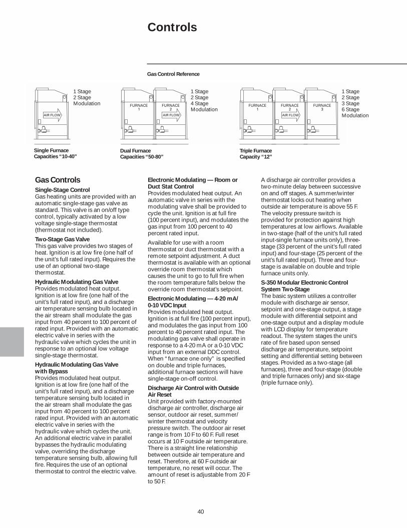
40
Gas Controls
Single-Stage ControlGas heating units are provided with anautomatic single-stage gas valve asstandard. This valve is an on/off typecontrol, typically activated by a lowvoltage single-stage thermostat(thermostat not included).
Two-Stage Gas ValveThis gas valve provides two stages ofheat. Ignition is at low fire (one half ofthe unit’s full rated input). Requires theuse of an optional two-stagethermostat.
Hydraulic Modulating Gas ValveProvides modulated heat output.Ignition is at low fire (one half of theunit’s full rated input), and a dischargeair temperature sensing bulb located inthe air stream shall modulate the gasinput from 40 percent to 100 percent ofrated input. Provided with an automaticelectric valve in series with thehydraulic valve which cycles the unit inresponse to an optional low voltagesingle-stage thermostat.
Hydraulic Modulating Gas Valvewith BypassProvides modulated heat output.Ignition is at low fire (one half of theunit’s full rated input), and a dischargetemperature sensing bulb located inthe air stream shall modulate the gasinput from 40 percent to 100 percentrated input. Provided with an automaticelectric valve in series with thehydraulic valve which cycles the unit.An additional electric valve in parallelbypasses the hydraulic modulatingvalve, overriding the dischargetemperature sensing bulb, allowing fullfire. Requires the use of an optionalthermostat to control the electric valve.
Electronic Modulating — Room orDuct Stat ControlProvides modulated heat output. Anautomatic valve in series with themodulating valve shall be provided tocycle the unit. Ignition is at full fire(100 percent input), and modulates thegas input from 100 percent to 40percent rated input.
Available for use with a roomthermostat or duct thermostat with aremote setpoint adjustment. A ductthermostat is available with an optionaloverride room thermostat whichcauses the unit to go to full fire whenthe room temperature falls below theoverride room thermostat’s setpoint.
Electronic Modulating — 4-20 mA/0-10 VDC InputProvides modulated heat output.Ignition is at full fire (100 percent input),and modulates the gas input from 100percent to 40 percent rated input. Themodulating gas valve shall operate inresponse to a 4-20 mA or a 0-10 VDCinput from an external DDC control.When “furnace one only” is specifiedon double and triple furnaces,additional furnace sections will havesingle-stage on-off control.
Discharge Air Control with OutsideAir ResetUnit provided with factory-mounteddischarge air controller, discharge airsensor, outdoor air reset, summer/winter thermostat and velocitypressure switch. The outdoor air resetrange is from 10 F to 60 F. Full resetoccurs at 10 F outside air temperature.There is a straight line relationshipbetween outside air temperature andreset. Therefore, at 60 F outside airtemperature, no reset will occur. Theamount of reset is adjustable from 20 Fto 50 F.
Controls
A discharge air controller provides atwo-minute delay between successiveon and off stages. A summer/winterthermostat locks out heating whenoutside air temperature is above 55 F.The velocity pressure switch isprovided for protection against hightemperatures at low airflows. Availablein two-stage (half of the unit’s full ratedinput-single furnace units only), three-stage (33 percent of the unit’s full ratedinput) and four-stage (25 percent of theunit’s full rated input). Three and four-stage is available on double and triplefurnace units only.
S-350 Modular Electronic ControlSystem Two-StageThe basic system utilizes a controllermodule with discharge air sensor,setpoint and one-stage output, a stagemodule with differential setpoint andone-stage output and a display modulewith LCD display for temperaturereadout. The system stages the unit’srate of fire based upon senseddischarge air temperature, setpointsetting and differential setting betweenstages. Provided as a two-stage (allfurnaces), three and four-stage (doubleand triple furnaces only) and six-stage(triple furnace only).
Gas Control Reference
1 Stage2 StageModulation
1 Stage2 Stage4 StageModulation
1 Stage2 Stage3 Stage6 StageModulation
Single FurnaceCapacities “10-40”
Dual FurnaceCapacities “50-80”
Triple FurnaceCapacity “12”

41
DimensionalData
DIMENSIONS ARE IN INCHES, DIMENSIONS INPARENTHESES ARE IN MILLIMETERS.
Standard Blower Module for Arrangements B, DUnit Sizes 10-80 (100-800 MBh)
STANDARD BLOWER MODULEUnit Sizes 10-80
(Left Hand Service Access Shown)
Note: The dimensions shown do not include base skid rail.
Model A B J10/15 32 7/8” 15 9/16” 24”
(835) (395) (610)20/25/50 43 7/8” 23 13/16” 35”
(1114) (605) (889)30/35 54 7/8” 34 13/16” 46”60/70 (1394) (884) (1168)40/80 60 3/4” 45 13/16” 51 1/2”
(1534) (1164) (1308)

42
DimensionalData
DIMENSIONS ARE IN INCHES, DIMENSIONS INPARENTHESES ARE IN MILLIMETERS.
HIGH CFM BLOWER MODULE*For Cooling Arrangements Only(Left Hand Service Access Shown)
Note: The dimensions shown do not include base skid rail.
Model A B ∆J10/15* 32 7/8” 15 9/16” 24”
(835) (395) (610)20/25/50 43 7/8” 23 13/16” 35”
(1114) (605) (889)30/35 54 7/8” 34 13/16” 46”60/70 (1394) (884) (1168)
40/80/12 60 3/8” 45 13/16” 51 1/2”(1534) (1164) (1308)
Detail DrawingHigh CFM Blower Module for Arrangement GUnit Sizes 10-12 (100-1200 MBh)100 and 150 MBh Units Not Available on Arrangement G

43
DimensionalData
Over/Under Air Intake without HoodArrangements B, D, G, KUnit Sizes 10-12 (100-1200 MBh)
DIMENSIONS ARE IN INCHES, DIMENSIONS INPARENTHESES ARE IN MILLIMETERS.
Model E Dimension10/15 27 3/4”
(705)20/25/50 38 3/4”
(984)30/35 49 3/4”60/70 (1264)
40/80/12 55 1/4”(1403)

44
DimensionalData
DIMENSIONS ARE IN INCHES, DIMENSIONSIN PARENTHESES ARE IN MILLIMETERS.
Coil ModuleArrangement KUnit Sizes 10-80 (100-800 MBh)
“L” Inside Max.Unit Size Cabinet Opening
10/15 32 1/4” (794)20/25/50 42 1/4” (1073)
30/35/60/70 53 1/4” (1353)40/80 58 3/4” (1492)
Model A10/15 32 7/8”
(835)20/25/50 43 7/8”
(1114)30/35 54 7/8”60/70 (1394)40/80 60 3/8”
(1534)
Side Opening of Cooling Module
• The coil section drain pan connection is 3/4 inch NPT pipe thread. It is a female fitting thatjust protrudes outside of the unit base rail. It is located on the service side of the unit.
• The drain pan is constructed of stainless steel, including the fitting. It is sloped towards thecenter of the pan and level across the width of the unit.
• P-trap required external to the unit provided by others.

45
DimensionalData
DIMENSIONS ARE IN INCHES, DIMENSIONS INPARENTHESES ARE IN MILLIMETERS.
Evaporative Cooler ModuleArrangement DUnit Sizes 10-80 (100-800 MBh)
EVAPORATIVE COOLER MODULEModels 10/80
Model A10/15 32 7/8”
(835)20/25/50 43 7/8”
(1114)30/35 54 7/8”60/70 (1394)40/80 60 3/8”
(1534)

46
DimensionalData
GRAVITY VENT(Left Hand Unit Shown)
Dimensions are in inches.Dimensions in parentheses are in millimeters.
Unit Dimensional DataGas Inlet
Capacity A B NAT LP F* G H J M S10 32 7/8 15 9/16 1/2 1/2 16 3/8 31 1/16 40 5/8 24 21 1/4 6 R
(835) (395) (416) (789) (1032) (610) (540) (152)15 32 7/8 18 5/16 1/2 1/2 20 1/2 31 1/16 45 5/8 24 20 1/4 7 R
(835) (465) (521) (789) (1159) (610) (514) (178)20 43 7/8 23 13/16 1/2 1/2 23 1/2 42 1/16 45 5/8 35 20 1/4 8 R
(1114) (605) (597) (1068) (1159) (889) (514) (203)25 43 7/8 29 5/16 3/4 1/2 OR 3/4 31 1/2 42 1/16 45 5/8 35 20 1/4 8 R
(1114) (745) (800) (1068) (1159) (889) (514) (203)30 54 7/8 34 13/16 3/4 1/2 OR 3/4 34 1/4 53 1/16 45 5/8 46 20 1/4 10 OV
(1394) (884) (870) (1348) (1159) (1168) (514) (254)35 54 7/8 40 5/16 3/4 1/2 OR 3/4 42 1/4 53 1/16 45 5/8 46 20 1/4 10 OV
(1394) (1024) (1073) (1348) (1159) (1168) (514) (254)40 60 3/8 45 13/16 3/4 1/2 OR 3/4 48 58 9/16 45 5/8 51 1/2 21 1/4 12 OV
(1534) (1164) (1219) (1487) (1159) (1308) (540) (305)
Note:Dimensions are in inches (Dimensions in parentheses are in millimeters).*“F” Dimension is the recommended clearance to service the burner drawer.“J” is an outside dimension for return air dampers.“S” Dimension Legend: R = Round; OV = Oval.
Indoor Make-Up Air Handler with Standard Blower – Arrangement BModels GSAA, GSBA – 10, 15, 20, 25, 30, 35, 40 (100-400 MBh)Single Furnace

47
DimensionalData
Indoor Make-Up Air Handler with Standard Blower and Evaporative Cooler – Arrangement DModels GSAA, GSBA – 10, 15, 20, 25, 30, 35, 40 (100-400 MBh)Single Furnace
GRAVITY VENT(Left Hand Unit Shown)
Dimensions are in inches.Dimensions in parentheses are in millimeters.
Unit Dimensional DataGas Inlet
Capacity A B NAT LP F* G H J M S10 32 7/8 15 9/16 1/2 1/2 16 3/8 31 1/16 40 5/8 24 21 1/4 6 R
(835) (395) (416) (789) (1032) (610) (540) (152)15 32 7/8 18 5/16 1/2 1/2 20 1/2 31 1/16 45 5/8 24 20 1/4 7 R
(835) (465) (521) (789) (1159) (610) (514) (178)20 43 7/8 23 13/16 1/2 1/2 23 1/2 42 1/16 45 5/8 35 20 1/4 8 R
(1114) (605) (597) (1068) (1159) (889) (514) (203)25 43 7/8 29 5/16 3/4 1/2 OR 3/4 31 1/2 42 1/16 45 5/8 35 20 1/4 8 R
(1114) (745) (800) (1068) (1159) (889) (514) (203)30 54 7/8 34 13/16 3/4 1/2 OR 3/4 34 1/4 53 1/16 45 5/8 46 20 1/4 10 OV
(1394) (884) (870) (1348) (1159) (1168) (514) (254)35 54 7/8 40 5/16 3/4 1/2 OR 3/4 42 1/4 53 1/16 45 5/8 46 20 1/4 10 OV
(1394) (1024) (1073) (1348) (1159) (1168) (514) (254)40 60 3/8 45 13/16 3/4 1/2 OR 3/4 48 58 9/16 45 5/8 51 1/2 21 1/4 12 OV
(1534) (1164) (1219) (1487) (1159) (1308) (540) (305)
Note:Dimensions are in inches (Dimensions in parentheses are in millimeters).*“F” Dimension is the recommended clearance to service the burner drawer.“J” is an outside dimension for return air dampers.“S” Dimension Legend: R = Round; OV = Oval.

48
GRAVITY VENT(Left Hand Unit Shown)
Dimensions are in inches.Dimensions in parentheses are in millimeters.
Unit Dimensional DataGas Inlet
Capacity A B NAT LP F* G H J M S20 43 7/8 23 13/16 1/2 1/2 23 1/2 42 1/16 45 5/8 35 20 1/4 8 R
(1114) (605) (597) (1068) (1159) (889) (514) (203)25 43 7/8 29 5/16 3/4 1/2 OR 3/4 31 1/2 42 1/16 45 5/8 35 20 1/4 8 R
(1114) (745) (800) (1068) (1159) (889) (514) (203)30 54 7/8 34 13/16 3/4 1/2 OR 3/4 34 1/4 53 1/16 45 5/8 46 20 1/4 10 OV
(1394) (884) (870) (1348) (1159) (1168) (514) (254)35 54 7/8 40 5/16 3/4 1/2 OR 3/4 42 1/4 53 1/16 45 5/8 46 20 1/4 10 OV
(1394) (1024) (1073) (1348) (1159) (1168) (514) (254)40 60 3/8 45 13/16 3/4 1/2 OR 3/4 48 58 9/16 45 5/8 51 1/2 21 1/4 12 OV
(1534) (1164) (1219) (1487) (1159) (1308) (540) (305)Note:Dimensions are in inches (Dimensions in parentheses are in millimeters).*“F” Dimension is the recommended clearance to service the burner drawer.“J” is an outside dimension for return air dampers.“S” Dimension Legend: R = Round; OV = Oval.
DimensionalData
Indoor Make-Up Air Handler with High Cfm Blower – Arrangement GModels GSAA, GSBA – 20, 25, 30, 35, 40 (200-400 MBh)Single Furnace

49
DimensionalData
Indoor Make-Up Air Handler with High Cfm Blower and Cooling Coil Section – Arrangement KModels GSAA, GSBA – 10, 15, 20, 25, 30, 35, 40 (100-400 MBh)
GRAVITY VENT(Left Hand Unit Shown)
Dimensions are in inches.Dimensions in parentheses are in millimeters.
Unit Dimensional DataGas Inlet
Capacity A B NAT LP F* G H J M S10 32 7/8 15 9/16 1/2 1/2 16 3/8 31 1/16 40 5/8 24 21 1/4 6 R
(835) (395) (416) (789) (1032) (610) (540) (152)15 32 7/8 18 5/16 1/2 1/2 20 1/2 31 1/16 45 5/8 24 20 1/4 7 R
(835) (465) (521) (789) (1159) (610) (514) (178)20 43 7/8 23 13/16 1/2 1/2 23 1/2 42 1/16 45 5/8 35 20 1/4 8 R
(1114) (605) (597) (1068) (1159) (889) (514) (203)25 43 7/8 29 5/16 3/4 1/2 OR 3/4 31 1/2 42 1/16 45 5/8 35 20 1/4 8 R
(1114) (745) (800) (1068) (1159) (889) (514) (203)30 54 7/8 34 13/16 3/4 1/2 OR 3/4 34 1/4 53 1/16 45 5/8 46 20 1/4 10 OV
(1394) (884) (870) (1348) (1159) (1168) (514) (254)35 54 7/8 40 5/16 3/4 1/2 OR 3/4 42 1/4 53 1/16 45 5/8 46 20 1/4 10 OV
(1394) (1024) (1073) (1348) (1159) (1168) (514) (254)40 60 3/8 45 13/16 3/4 1/2 OR 3/4 48 58 9/16 45 5/8 51 1/2 21 1/4 12 OV
(1534) (1164) (1219) (1487) (1159) (1308) (540) (305)
Note:Dimensions are in inches (Dimensions in parentheses are in millimeters).*“F” Dimension is the recommended clearance to service the burner drawer.“J” is an outside dimension for return air dampers.“S” Dimension Legend: R = Round; OV = Oval.

50
Dimensions are in inches.Dimensions in parentheses are in millimeters.
Unit Dimensional DataCapacity A B F* G M S
50 31 5/8 29 5/16 37 5/8 41 1/8 20 1/4 8 R(803) (745) (956) (1045) (514) (203)
60 37 1/8 34 13/16 43 18 52 1/8 20 1/4 10 OV(943) (884) (1095) (1324) (514) (254)
70 42 5/8 40 5/16 48 5/8 52 1/8 20 1/4 10 OV(1083) (1024) (1235) (1324) (514) (254)
80 48 1/8 45 13/16 54 1/8 57 5/8 21 1/4 12 OV(1222) (1164) (1375) (1464) (540) (305)
Note:Dimensions are in inches (Dimensions in parentheses are in millimeters).*“F” Dimension is the recommended clearance to service the burner drawer.“S” Dimension Legend: R = Round; OV = Oval.Gas inlet sizes: Natural Gas = 3/4” Dia. LP Gas = 1/2” or 3/4” Dia.
DimensionalData
Indoor Duct Furnace – Arrangement AModels GDAA, GDBA – 50, 60, 70, 80 (500-800 MBh)Double Furnace
GRAVITY VENT(Left Hand Unit Shown)

51
GRAVITY VENT(Left Hand Unit Shown)
Dimensions are in inches.Dimensions in parentheses are in millimeters.
Unit Dimensional DataGas Inlet
Capacity A B NAT LP F* G H J M S50 43 7/8 29 5/16 3/4 1/2 OR 3/4 31 1/2 42 1/16 45 5/8 35 20 1/4 8 R
(1114) (745) (800) (1068) (1159) (889) (514) (203)60 54 7/8 34 13/16 3/4 1/2 OR 3/4 34 1/4 53 1/16 45 5/8 46 20 1/4 10 OV
(1394) (884) (870) (1348) (1159) (1168) (514) (254)70 54 7/8 40 5/16 3/4 1/2 OR 3/4 42 1/4 53 1/16 45 5/8 46 20 1/4 10 OV
(1394) (1024) (1073) (1348) (1159) (1168) (514) (254)80 60 3/8 45 13/16 3/4 1/2 OR 3/4 48 58 9/16 45 5/8 51 1/2 21 1/4 12 OV
(1534) (1164) (1219) (1487) (1159) (1308) (540) (305)Note:Dimensions are in inches (Dimensions in parentheses are in millimeters).*“F” Dimension is the recommended clearance to service the burner drawer.“J” is an outside dimension for return air dampers.“S” Dimension Legend: R = Round; OV = Oval.
DimensionalData
Indoor Make-Up Air Handler with Standard Blower – Arrangement BModels GSAA, GSBA – 50, 60, 70, 80 (500-800 MBh)Double Furnace

52
DimensionalData
Indoor Make-Up Air Handler with Standard Blower and Evaporative Cooler – Arrangement DModels GSAA, GSBA – 50, 60, 70, 80 (500-800 MBh)Double Furnace
GRAVITY VENT(Left Hand Unit Shown)
Dimensions are in inches.Dimensions in parentheses are in millimeters.
Unit Dimensional DataGas Inlet
Capacity A B NAT LP F* G H J M S50 43 7/8 29 5/16 3/4 1/2 OR 3/4 31 1/2 42 1/16 45 5/8 35 20 1/4 8 R
(1114) (745) (800) (1068) (1159) (889) (514) (203)60 54 7/8 34 13/16 3/4 1/2 OR 3/4 34 1/4 53 1/16 45 5/8 46 20 1/4 10 OV
(1394) (884) (870) (1348) (1159) (1168) (514) (254)70 54 7/8 40 5/16 3/4 1/2 OR 3/4 42 1/4 53 1/16 45 5/8 46 20 1/4 10 OV
(1394) (1024) (1073) (1348) (1159) (1168) (514) (254)80 60 3/8 45 13/16 3/4 1/2 OR 3/4 48 58 9/16 45 5/8 51 1/2 21 1/4 12 OV
(1534) (1164) (1219) (1487) (1159) (1308) (540) (305)
Note:Dimensions are in inches (Dimensions in parentheses are in millimeters).*“F” Dimension is the recommended clearance to service the burner drawer.“J” is an outside dimension for return air dampers.“S” Dimension Legend: R = Round; OV = Oval.

53
DimensionalData
Indoor Make-Up Air Handler with High Cfm Blower – Arrangement GModels GSAA, GSBA – 50, 60, 70, 80 (500-800 MBh)Double Furnace
GRAVITY VENT(Left Hand Unit Shown)
Dimensions are in inches.Dimensions in parentheses are in millimeters.
Unit Dimensional DataGas Inlet
Capacity A B NAT LP F* G H J M S50 43 7/8 29 5/16 3/4 1/2 OR 3/4 31 1/2 42 1/16 45 5/8 35 20 1/4 8 R
(1114) (745) (800) (1068) (1159) (889) (514) (203)60 54 7/8 34 13/16 3/4 1/2 OR 3/4 34 1/4 53 1/16 45 5/8 46 20 1/4 10 OV
(1394) (884) (870) (1348) (1159) (1168) (514) (254)70 54 7/8 40 5/16 3/4 1/2 OR 3/4 42 1/4 53 1/16 45 5/8 46 20 1/4 10 OV
(1394) (1024) (1073) (1348) (1159) (1168) (514) (254)80 60 3/8 45 13/16 3/4 1/2 OR 3/4 48 58 9/16 45 5/8 51 1/2 21 1/4 12 OV
(1534) (1164) (1219) (1487) (1159) (1308) (540) (305)
Note:Dimensions are in inches (Dimensions in parentheses are in millimeters).*“F” Dimension is the recommended clearance to service the burner drawer.“J” is an outside dimension for return air dampers.“S” Dimension Legend: R = Round; OV = Oval.

54
GRAVITY VENT(Left Hand Unit Shown)
Dimensions are in inches.Dimensions in parentheses are in millimeters.
Unit Dimensional DataGas Inlet
Capacity A B NAT LP F* G H J M S50 43 7/8 29 5/16 3/4 1/2 OR 3/4 31 1/2 42 1/16 45 5/8 35 20 1/4 8 R
(1114) (745) (800) (1068) (1159) (889) (514) (203)60 54 7/8 34 13/16 3/4 1/2 OR 3/4 34 1/4 53 1/16 45 5/8 46 20 1/4 10 OV
(1394) (884) (870) (1348) (1159) (1168) (514) (254)70 54 7/8 40 5/16 3/4 1/2 OR 3/4 42 1/4 53 1/16 45 5/8 46 20 1/4 10 OV
(1394) (1024) (1073) (1348) (1159) (1168) (514) (254)80 60 3/8 45 13/16 3/4 1/2 OR 3/4 48 58 9/16 45 5/8 51 1/2 21 1/4 12 OV
(1534) (1164) (1219) (1487) (1159) (1308) (540) (305)Note:Dimensions are in inches (Dimensions in parentheses are in millimeters).*“F” Dimension is the recommended clearance to service the burner drawer.“J” is an outside dimension for return air dampers.“S” Dimension Legend: R = Round; OV = Oval.
DimensionalData
Indoor Make-Up Air Handler with High Cfm Blower and Cooling Coil Section – Arrangement KModels GSAA, GSBA – 50, 60, 70, 80 (500-800 MBh)Double Furnace

55
DimensionalData
Indoor Make-Up Air Handler with High Cfm Blower – Arrangement GModels GSAA, GSBA – 12 (1200 MBh)Triple Furnace
GRAVITY VENT(Left Hand Unit Shown)
Dimensions are in inches.Dimensions in parentheses are in millimeters.
Indoor Duct Furnace – Arrangement AModels GDAA, GDBA – 12 (1200 MBh)Triple Furnace
GRAVITY VENT(Left Hand Unit Shown)

56
DimensionalData
High Efficiency Indoor Make-Up Air Handler with Standard Blower – Arrangement BModels GGAA, GGBA – 10, 15, 20, 25, 30, 35, 40 (100-400 MBh)Single Furnace
POWER VENT(Left Hand Unit Shown)
Dimensions are in inches.Dimensions in parentheses are in millimeters.
Unit Dimensional DataGas Inlet
Capacity A B NAT LP F* G J **V Dia.10 32 7/8 15 9/16 1/2 1/2 16 3/8 31 1/16 24 **4
(835) (395) (416) (789) (610) (102)15 32 7/8 18 5/16 1/2 1/2 20 1/2 31 1/16 24 **4
(835) (465) (521) (789) (610) (102)20 43 7/8 23 13/16 1/2 1/2 23 1/2 42 1/16 35 5
(1114) (605) (597) (1068) (889) (127)25 43 7/8 29 5/16 3/4 1/2 OR 3/4 31 1/2 42 1/16 35 5
(1114) (745) (800) (1068) (889) (127)30 54 7/8 34 13/16 3/4 1/2 OR 3/4 34 1/4 53 1/16 46 **6
(1394) (884) (870) (1348) (1168) (152)35 54 7/8 40 5/16 3/4 1/2 OR 3/4 42 1/4 53 1/16 46 **6
(1394) (1024) (1073) (1348) (1168) (152)40 60 3/8 45 13/16 3/4 1/2 OR 3/4 48 58 9/16 51 1/2 **6
(1534) (1164) (1219) (1487) (1308) (152)
Note:Dimensions are in inches (Dimensions in parentheses are in millimeters).*“F” Dimension is the recommended clearance to service the burner drawer.** “V Dia.” = The Flue Opening; Capacities 10 & 15 will require a field installed 5” to 4” Dia. reducer. Capacities 30/35/40 will require a field installed 5” to 6” Dia.
increaser that will be supplied with the unit.“J” is an outside dimension for outside or return air dampers.

57
DimensionalData
High Efficiency Indoor Make-Up Air Handler with Standard Blower and Evaporative Cooler – Arrangement DModels GGAA, GGBA – 10, 15, 20, 25, 30, 35, 40 (100-400 MBh)Single Furnace
POWER VENT(Left Hand Unit Shown)
Dimensions are in inches.Dimensions in parentheses are in millimeters.
Unit Dimensional DataGas Inlet
Capacity A B NAT LP F* G J **V Dia.10 32 7/8 15 9/16 1/2 1/2 16 3/8 31 1/16 24 **4
(835) (395) (416) (789) (610) (102)15 32 7/8 18 5/16 1/2 1/2 20 1/2 31 1/16 24 **4
(835) (465) (521) (789) (610) (102)20 43 7/8 23 13/16 1/2 1/2 23 1/2 42 1/16 35 5
(1114) (605) (597) (1068) (889) (127)25 43 7/8 29 5/16 3/4 1/2 OR 3/4 31 1/2 42 1/16 35 5
(1114) (745) (800) (1068) (889) (127)30 54 7/8 34 13/16 3/4 1/2 OR 3/4 34 1/4 53 1/16 46 **6
(1394) (884) (870) (1348) (1168) (152)35 54 7/8 40 5/16 3/4 1/2 OR 3/4 42 1/4 53 1/16 46 **6
(1394) (1024) (1073) (1348) (1168) (152)40 60 3/8 45 13/16 3/4 1/2 OR 3/4 48 58 9/16 51 1/2 **6
(1534) (1164) (1219) (1487) (1308) (152)
Note:Dimensions are in inches (Dimensions in parentheses are in millimeters).*“F” Dimension is the recommended clearance to service the burner drawer.** “V Dia.” = The Flue Opening; Capacities 10 & 15 will require a field installed 5” to 4” Dia. reducer. Capacities 30/35/40 will require a field installed 5” to 6” Dia.
increaser that will be supplied with the unit.“J” is an outside dimension for outside or return air dampers.

58
DimensionalData
POWER VENT(Left Hand Unit Shown)
Dimensions are in inches.Dimensions in parentheses are in millimeters.
Unit Dimensional DataGas Inlet
Capacity A B NAT LP F* G J **V Dia.20 43 7/8 23 13/16 1/2 1/2 23 1/2 42 1/16 35 5
(1114) (605) (597) (1068) (889) (127)25 43 7/8 29 5/16 3/4 1/2 OR 3/4 31 1/2 42 1/16 35 5
(1114) (745) (800) (1068) (889) (127)30 54 7/8 34 13/16 3/4 1/2 OR 3/4 34 1/4 53 1/16 46 **6
(1394) (884) (870) (1348) (1168) (152)35 54 7/8 40 5/16 3/4 1/2 OR 3/4 42 1/4 53 1/16 46 **6
(1394) (1024) (1073) (1348) (1168) (152)40 60 3/8 45 13/16 3/4 1/2 OR 3/4 48 58 9/16 51 1/2 **6
(1534) (1164) (1219) (1487) (1308) (152)Note:Dimensions are in inches (Dimensions in parentheses are in millimeters).*“F” Dimension is the recommended clearance to service the burner drawer.** “V Dia.” = The Flue Opening; Capacities 30/35/40 will require a field installed 5” to 6” Dia. increaser that will be supplied with the unit.“J” is an outside dimension for outside or return air dampers.
High Efficiency Indoor Make-Up Air Handler with High Cfm Blower – Arrangement GModels GGAA, GGBA – 20, 25, 30, 35, 40 (200-400 MBh)Single Furnace

59
DimensionalData
POWER VENT(Left Hand Unit Shown)
Dimensions are in inches.Dimensions in parentheses are in millimeters.
Unit Dimensional DataGas Inlet
Capacity A B NAT LP F* G J **V Dia.10 32 7/8 15 9/16 1/2 1/2 16 3/8 31 1/16 24 **4
(835) (395) (416) (789) (610) (102)15 32 7/8 18 5/16 1/2 1/2 20 1/2 31 1/16 24 **4
(835) (465) (521) (789) (610) (102)20 43 7/8 23 13/16 1/2 1/2 23 1/2 42 1/16 35 5
(1114) (605) (597) (1068) (889) (127)25 43 7/8 29 5/16 3/4 1/2 OR 3/4 31 1/2 42 1/16 35 5
(1114) (745) (800) (1068) (889) (127)30 54 7/8 34 13/16 3/4 1/2 OR 3/4 34 1/4 53 1/16 46 **6
(1394) (884) (870) (1348) (1168) (152)35 54 7/8 40 5/16 3/4 1/2 OR 3/4 42 1/4 53 1/16 46 **6
(1394) (1024) (1073) (1348) (1168) (152)40 60 3/8 45 13/16 3/4 1/2 OR 3/4 48 58 9/16 51 1/2 **6
(1534) (1164) (1219) (1487) (1308) (152)
Note:Dimensions are in inches (Dimensions in parentheses are in millimeters).*“F” Dimension is the recommended clearance to service the burner drawer.** “V Dia.” = The Flue Opening; Capacities 10 & 15 will require a field installed 5” to 4” Dia. reducer. Capacities 30/35/40 will require a field installed 5” to 6” Dia.
increaser that will be supplied with the unit.“J” is an outside dimension for outside or return air dampers.
High Efficiency Indoor Make-Up Air Handler with High Cfm Blower and Cooling Coil Section – Arrangement KModels GGAA, GGBA – 10, 15, 20, 25, 30, 35, 40 (100-400 MBh)
60
DimensionalData
Dimensions are in inches.Dimensions in parentheses are in millimeters.
Unit Dimensional DataCapacity A B F* G M V Dia.**
50 31 5/8 20 5/16 37 5/8 41 1/8 20 1/4 5(803) (745) (956) (1045) (514) (127)
60 37 1/8 34 3/16 43 18 52 1/8 20 1/4 6(943) (884) (1095) (1324) (514) (152)
70 42 5/8 40 5/16 48 5/8 52 1/8 20 1/4 6(1083) (1024) (1235) (1324) (514) (152)
80 48 1/8 45 13/16 54 1/8 57 5/8 21 1/4 6(1222) (1164) (1375) (1464) (540) (152)
Note:Dimensions are in inches (Dimensions in parentheses are in millimeters).*“F” Dimension is the recommended clearance to service the burner drawer.**“V” Dia. = Flue Opening (ME - Power Vent Units Only). The 5” to 6” increaser adapter is supplied by the manufacturer for unit capacities 60, 70 and 80.Gas inlet sizes: Natural Gas = 3/4” Dia. LP Gas = 1/2” or 3/4” Dia.
High Efficiency Indoor Duct Furnace – Arrangement AModels GGAA, GGBA – 50, 60, 70, 80 (500-800 MBh)Double Furnace
POWER VENT(Left Hand Unit Shown)

61
DimensionalData
POWER VENT(Left Hand Unit Shown)
Dimensions are in inches.Dimensions in parentheses are in millimeters.
Unit Dimensional DataGas Inlet
Capacity A B NAT LP F* G J **V Dia.50 43 7/8 29 5/16 3/4 1/2 OR 3/4 31 1/2 42 1/16 35 5
(1114) (745) (800) (1068) (889) (127)60 54 7/8 34 13/16 3/4 1/2 OR 3/4 34 1/4 53 1/16 46 **6
(1394) (884) (870) (1348) (1168) (152)70 54 7/8 40 5/16 3/4 1/2 OR 3/4 42 1/4 53 1/16 46 **6
(1394) (1024) (1073) (1348) (1168) (152)80 60 3/8 45 13/16 3/4 1/2 OR 3/4 48 58 9/16 51 1/2 **6
(1534) (1164) (1219) (1487) (1308) (152)
Note:Dimensions are in inches (Dimensions in parentheses are in millimeters).*“F” Dimension is the recommended clearance to service the burner drawer.** “V Dia.” = The Flue Opening; Capacities 60/70/80 will require 5” to 6” increaser on each furnace that will be supplied with the unit.“J” is an outside dimension for outside or return air dampers.
High Efficiency Indoor Make-Up Air Handler with Standard Blower – Arrangement BModels GGAA, GGBA – 50, 60, 70, 80 (500-800 MBh)Double Furnace

62
POWER VENT(Left Hand Unit Shown)
Dimensions are in inches.Dimensions in parentheses are in millimeters.
Unit Dimensional DataGas Inlet
Capacity A B NAT LP F* G J **V Dia.50 43 7/8 29 5/16 3/4 1/2 OR 3/4 31 1/2 42 1/16 35 5
(1114) (745) (800) (1068) (889) (127)60 54 7/8 34 13/16 3/4 1/2 OR 3/4 34 1/4 53 1/16 46 **6
(1394) (884) (870) (1348) (1168) (152)70 54 7/8 40 5/16 3/4 1/2 OR 3/4 42 1/4 53 1/16 46 **6
(1394) (1024) (1073) (1348) (1168) (152)80 60 3/8 45 13/16 3/4 1/2 OR 3/4 48 58 9/16 51 1/2 **6
(1534) (1164) (1219) (1487) (1308) (152)
Note:Dimensions are in inches (Dimensions in parentheses are in millimeters).*“F” Dimension is the recommended clearance to service the burner drawer.** “V Dia.” = The Flue Opening; Capacities 60/70/80 will require 5” to 6” increaser on each furnace that will be supplied with the unit.“J” is an outside dimension for outside or return air dampers.
DimensionalData
High Efficiency Indoor Make-Up Air Handler with Standard Blower and Evaporative Cooler – Arrangement DModels GGAA, GGBA – 50, 60, 70, 80 (500-800 MBh)Double Furnace

63
DimensionalData
POWER VENT(Left Hand Unit Shown)
Dimensions are in inches.Dimensions in parentheses are in millimeters.
Unit Dimensional DataGas Inlet
Capacity A B NAT LP F* G J **V Dia.50 43 7/8 29 5/16 3/4 1/2 OR 3/4 31 1/2 42 1/16 35 5
(1114) (745) (800) (1068) (889) (127)60 54 7/8 34 13/16 3/4 1/2 OR 3/4 34 1/4 53 1/16 46 **6
(1394) (884) (870) (1348) (1168) (152)70 54 7/8 40 5/16 3/4 1/2 OR 3/4 42 1/4 53 1/16 46 **6
(1394) (1024) (1073) (1348) (1168) (152)80 60 3/8 45 13/16 3/4 1/2 OR 3/4 48 58 9/16 51 1/2 **6
(1534) (1164) (1219) (1487) (1308) (152)Note:Dimensions are in inches (Dimensions in parentheses are in millimeters).*“F” Dimension is the recommended clearance to service the burner drawer.** “V Dia.” = The Flue Opening; Capacities 60/70/80 will require 5” to 6” increaser on each furnace that will be supplied with the unit.“J” is an outside dimension for outside or return air dampers.
High Efficiency Indoor Make-Up Air Handler with High Cfm Blower – Arrangement GModels GGAA, GGBA – 50, 60, 70, 80 (500-800 MBh)Double Furnace

64
POWER VENT(Left Hand Unit Shown)
Dimensions are in inches.Dimensions in parentheses are in millimeters.
Unit Dimensional DataGas Inlet
Capacity A B NAT LP F* G J **V Dia.50 43 7/8 29 5/16 3/4 1/2 OR 3/4 31 1/2 42 1/16 35 5
(1114) (745) (800) (1068) (889) (127)60 54 7/8 34 13/16 3/4 1/2 OR 3/4 34 1/4 53 1/16 46 **6
(1394) (884) (870) (1348) (1168) (152)70 54 7/8 40 5/16 3/4 1/2 OR 3/4 42 1/4 53 1/16 46 **6
(1394) (1024) (1073) (1348) (1168) (152)80 60 3/8 45 13/16 3/4 1/2 OR 3/4 48 58 9/16 51 1/2 **6
(1534) (1164) (1219) (1487) (1308) (152)Note:Dimensions are in inches (Dimensions in parentheses are in millimeters).*“F” Dimension is the recommended clearance to service the burner drawer.** “V Dia.” = The Flue Opening; Capacities 60/70/80 will require 5” to 6” increaser on each furnace that will be supplied with the unit.“J” is an outside dimension for outside or return air dampers.
DimensionalData
High Efficiency Indoor Make-Up Air Handler with High Cfm Blower and Cooling Coil Section – Arrangement KModels GGAA, GGBA – 50, 60, 70, 80 (500-800 MBh)Double Furnace

65
DimensionalData
High Efficiency Indoor Make-Up Air Handler with High Cfm Blower – Arrangement GModels GGAA, GGBA – 12 (1200 MBh)Triple Furnace
POWER VENT(Left Hand Unit Shown)
Dimensions are in inches.Dimensions in parentheses are in millimeters.
POWER VENT(Left Hand Unit Shown)
Note:*Recommended clearance to service the burner drawer.
**6” Dia. = Flue Opening. The 5” to 6” increaser adapter is supplied by the manufacturer for this model.Gas inlet sizes: Natural Gas = 3/4” Dia. LP Gas = 1/2” or 3/4” Dia.
High Efficiency Indoor Duct Furnace – Arrangement AModels GGAA, GGBA – 12 (1200 MBh)Triple Furnace

66
Table W-1 – Indoor Make-Up Air Handler Unit Weight Data (Pounds)A B D G K Outside
Capacity Net Ship Net Ship Net Ship Net Ship Net Ship Air Hood10 NA NA 537 638 715 846 NA NA 775 930 4315 NA NA 566 667 744 875 NA NA 801 956 4320 NA NA 689 798 895 1035 848 988 950 1115 5125 NA NA 716 825 922 1062 898 1038 1000 1165 5130 NA NA 843 959 1083 1232 1066 1215 1176 1351 5935 NA NA 889 1005 1129 1279 1110 1259 1220 1395 5940 NA NA 950 1070 1206 1359 1183 1336 1302 1482 6350 589 686 1035 1169 1241 1406 1209 1374 1311 1501 5160 684 788 1219 1362 1459 1634 1434 1609 1544 1745 5970 734 838 1289 1432 1529 1704 1503 1678 1613 1814 5980 806 914 1386 1533 1642 1022 1612 1792 1730 1936 6312 1198 1333 NA NA NA NA 2040 2246 NA NA 63
Note:1. Weights do not include motors or coils.2. 1 lb. = 0.453 Kg.
Table W-2 – High Efficiency Indoor Make-Up Air Handler Unit Weight Data (Pounds)A B D G K Outside
Capacity Net Ship Net Ship Net Ship Net Ship Net Ship Air Hood10 NA NA 536 637 714 845 NA NA 774 929 4315 NA NA 561 662 739 870 NA NA 799 954 4320 NA NA 676 785 882 1022 832 972 938 1103 5125 NA NA 703 812 909 1049 881 1021 984 1149 5130 NA NA 821 937 1061 1210 1037 1186 1146 1321 5935 NA NA 867 983 1107 1256 1089 1238 1199 1374 5940 NA NA 928 1048 1184 1337 1161 1314 1280 1460 6350 589 686 1010 1144 1216 1381 1184 1349 1286 1476 5160 684 788 1175 1318 1415 1590 1390 1565 1500 1701 5970 734 838 1246 1389 1486 1661 1459 1634 1569 1770 5980 806 914 1343 1490 1599 1779 1568 1748 1687 1893 6312 1198 1333 NA NA NA NA 1975 2181 NA NA 63
Note:1. Weights do not include motors or coils.2. 1 lb. = 0.453 Kg.
Weights

67
Table W-3 – Motor WeightsVoltage 1/2 HP 3/4 HP 1 HP 1 1/2 HP 2 HP 3 HP 5 HP 7 1/2 HP 10 HP 15 HP115/60/1 ODP 20 25 25 40 42 80 NA NA NA NA208/60/1 ODP 21 27 25 40 66 80 NA NA NA NA230/60/1 ODP 21 25 25 40 42 80 NA NA NA NA208/60/3 ODP 20 24 31 29 35 47 49 99 118 152230/60/3 ODP 20 24 31 29 35 47 49 99 118 150460/60/3 ODP 20 24 31 29 35 47 49 99 118 150575/60/3 ODP 20 20 27 31 37 56 73 105 116 150115/60/1 TE 26 30 34 41 65 74 NA NA NA NA208/60/1 TE 27 36 39 48 65 74 NA NA NA NA230/60/1 TE 26 30 34 41 65 74 NA NA NA NA208/60/3 TE 18 23 28 32 36 55 65 90 123 295230/60/3 TE 18 23 28 32 36 55 65 90 123 295460/60/3 TE 18 23 28 32 36 55 65 90 123 295575/60/3 TE 21 21 26 36 40 90 92 161 199 284115/60/1 HEODP 32 33 38 58 72 NA NA NA NA NA208/60/1 HEODP 32 30 NA NA NA NA NA NA NA NA230/60/1 HEODP 32 33 38 58 72 NA NA NA NA NA208/60/3 HEODP 22 25 40 44 44 83 89 139 141 213230/60/3 HEODP 24 26 40 43 44 80 91 137 138 238460/60/3 HEODP 24 26 40 43 44 80 91 137 138 238575/60/3 HEODP NA NA 41 44 45 90 100 170 141 215115/60/1 HETE 28 37 38 41 53 NA NA NA NA NA208/60/1 HETE NA NA NA NA NA NA NA NA NA NA230/60/1 HETE 28 37 38 41 53 NA NA NA NA NA208/60/3 HETE NA NA 39 34 48 71 78 107 124 225230/60/3 HETE 32 52 39 34 48 94 110 158 166 294460/60/3 HETE 32 52 39 34 48 94 110 158 166 294575/60/3 HETE NA NA 44 69 88 76 80 132 140 260208/60/3 2S1W NA NA 34 38 48 66 81 125 143 NA230/60/3 2S1W NA NA 34 38 48 66 81 125 143 NA460/60/3 2S1W NA NA 34 38 41 58 94 125 136 218575/60/3 2S1W NA NA NA NA NA NA NA NA NA NA115/60/1 2S2W 23 30 37 NA NA NA NA NA NA NA208/60/1 2S2W NA 29 36 NA NA NA NA NA NA NA230/60/1 2S2W 23 29 36 NA NA NA NA NA NA NA208/60/3 2S2W 27 32 44 47 67 84 NA 221 192 NA230/60/3 2S2W 26 32 44 47 67 84 NA 221 192 NA460/60/3 2S2W 26 33 40 44 55 67 NA 214 230 NA575/60/3 2S2W NA NA NA NA NA NA NA NA NA NANotes:1. ODP = Open Drip Proof2. TE = Totally enclosed3. HEODP = High Efficiency Open Drip Proof4. HETE = High Efficiency Totally Enclosed5. 2S1W = Two Speed One Winding6. 2S2W = Two Speed Two Winding7. NA = Not Available
FLA based on NEC Ratings
Weights
Table W-4 – Evaporative Cooler WeightShipping Wt. Operating Wt.
Unit Size lb (Kg) lb (Kg)10, 15 137 30120, 25, 50 166 38630, 35, 60, 70 192 46840, 80 206 509
Metric Conversion:1 lb. = 0.453 Kg.

68
Options Thermostats
Single-Stage Room Thermostat(Order No. 134-0207-01)
• Low Voltage (24V)• 40 F to 90 F Range• Fan Auto-On Switch• System Heat-Off-Cool Switch• 311/16” Diameter; 13/4” Deep
Universal Guard(Order No. 134-0207-07)
• Clear Plastic• Ring Base• Tumbler Lock and Two Keys• Cover: 67/8” W 55/8” H 3“ D• Base: 69/16” W 51/2” H 3/8” D
T7300 Programmable RoomThermostat(Order No. 134-0207-05)
• Provides seven-day programmabilityfor two stages of heating and twostages of cooling.
• Heat-Off-Cool-Auto system switchingfour time periods per day for occupiedand unoccupied modes with three-hour override of unoccupied mode.
• Automatic heat-cool changeover andbattery backup.
Single-Stage Room Thermostatwith Summer/Winter Switch(Order No. 134-0207-02)
• Low Voltage (24V)• 55 to 95 F Range• Fan Auto-On Switch• 31/2” W 41/5” H 13/8” D
Two-Stage Room Thermostat(Order No. 134-0207-04)
• Low Voltage (24V)• 40 F to 90 F Range• Fan Auto-On Switch• System Off-Heat-Auto-Cool Switch• 55/8” W 31/2” H 21/8” D

69
Single-Stage Duct Thermostat(Order No. 134-0207-03)
• Low Voltage (24V)• 55 to 175 F Range• 5’ Capillary• 2” W 55/8” H 27/16” D
Two-Stage Duct Thermostat(Order No. 134-0207-06)
• Low Voltage (24V)• 55 to 175 F Range• 5’ Capillary• 2” W 55/8” H 27/16” D
Remote Control Station(Order No. 134-0201-01)
• Wall mounted• Six LED status lamps• System on/off, fan auto/on, heat auto/
off, cool auto/off, auxiliary on/offswitching and modulating damperpotentiometer mounting.
• Plug-in terminal block wiring and wallmounting bracket.
• 61/4” W x 33/4” H x 11/2” D
Options Thermostats
Seven-Day Timeclock(Order No. 134-0201-02)
• Single pole double throw (SPDT) relayoutput at setpoint time
• Maximum of six setpoints per day• 73/4” H x 5” W x 37/16” D
24-Hour Timeclock(Order No. 134-0201-03)
• Single pole double throw (SPDT) relayoutput at setpoint time.
• Maximum 12 setpoints per day.• 73/4” H x 5” W x 37/16” D

70
Options Controls
Electronic Modulating RoomThermostat(Included with Gas Control)
• Low voltage (24 V)• 60-85 F range• Room thermostat• 41/2” H x 21/2” W x 11/2” D
Discharge Air Control with OutsideAir Reset
• Available in two, three and four-stagecontrol. Shown above is the dischargeair controller.
Electronic Modulating4-20 mA or 0-10 VDC Input
• A200 signal conditioner.• Control replaces amplifier in duct or
room control package.
Electronic Modulating DuctThermostat with RoomOverride
• Line voltage (115 V) roomstat• 50-90 F range• 27/8” W x 49/16” H x 11/4” D• Low voltage (24 V) Ductstat• 55-90 F range• Sensor: 10-inch probe• Remote temperature selector:
41/4” W x 41/4” H x 15/8” D• Duct thermostat:
41/4” W x 41/4” H x 15/8” D
Electronic Modulating DuctThermostat(Included with Gas Control)
• Low voltage (24 V)• 55-90 F range• Sensor: 10-inch probe• Remote temperature selector:
41/4” W x 41/4” H x 17/8” D• Duct thermostat:
41/4” W x 41/4” H x 15/8” D

71
FeaturesSummary
Trane indoor gas heating units have thefollowing design features:
• All units have AGA and CGA certifiedduct furnaces.
• All units are fabricated from aluminizedsteel. The heat exchanger uses 20-gauge tubes and 18-gauge headersections.
• Units are complete, wired, tested andrail-mounted packages with blowerdrives preset.
• Units are available with left hand orright hand gas control configuration.This flexibility helps to meet specialapplication requirements.
• Draw-thru cabinet arrangements havea stainless steel drain pan.
• Evaporative cooling arrangement comewith a standard 8 or optional 12-inchmedia (203 or 305 mm).

72
MechanicalSpecifications
Indoor Gas Duct FurnacesArrangement A50-80 (500-800 MBH)
GeneralUnits are completely factoryassembled, piped, wired and test fired.All units are AGA Certified and conformwith the latest ANSI Standards for safeand efficient performance. Units areprovided with four point suspensionhangers. All units are available foroperation on either natural or LP(propane) gas.
CasingCasings are die-formed, 20-gaugegalvanized steel and finished in bakedenamel. The bottom panel is easilyremoved to provide service access tothe burners, pilot and orifices. The pilotis also accessible through a side panelaccess plate. The high limit switch isaccessible through a side panel access.
Duct discharge flanges for simpleductwork connection are provided.
Heat ExchangerStandard heat exchanger constructionconsists of seam welded 20-gaugealuminized steel tubes and 18-gaugealuminized steel headers.
Draft DiverterStandard draft diverter construction iscorrosion resistant aluminized steel.
BurnersBurners are die-formed, corrosionresistant aluminized steel, withstainless steel port protectors. Portprotectors prevent scale or foreignmatter from obstructing the burnerports. Burners are individuallyremovable for ease of inspection andservicing. Each burner is provided withan individually adjustable, manuallyrotated air shutter adjustment. Airshutter adjustment is fixed.
ControlsA factory installed junction box isprovided for all power connections.Standard units are provided with a24-volt combination single-stageautomatic gas valve, including mainoperating valve and pilot safety shutoff,pressure regulator, manual main andpilot shutoff valve, and adjustable pilotvalve. Gas valve is suitable to amaximum inlet pressure of 0.5 psi(14-inch W.C.) on natural gas. A 24-voltcontrol transformer, a spill (blockedvent) switch and a high limit areprovided.
All units are provided with a solid-stateignition control system which ignitesthe intermittent pilot by spark duringeach cycle of operation. When the pilotflame is proven, the main burner valveopens to allow gas flow to the burners.Pilot and burners are extinguishedduring the off cycle.
FACTORY INSTALLED OPTIONS
Control Options (Per Furnace)
Two-Stage Gas ValveProvides two stages of heat. Ignition isat low fire (40% of the unit’s full ratedinput). Requires the use of an optionaltwo-stage thermostat.
Hydraulic Modulating Gas ValveProvides modulated heat output.Ignition is at low fire (40% of the unit’sfull rated input) and a discharge airtemperature sensing bulb located inthe air stream shall modulate the gasinput from 40% to 100% rated input.Provided with an automatic electricvalve in series with the hydraulic valvewhich cycles the unit in response to anoptional low voltage single-stagethermostat.
Hydraulic Modulating Gas Valve withBypassProvides modulated heat output.Ignition is at low fire (40% of the unit’sfull rated input) and a discharge airtemperature sensing bulb located inthe air stream shall modulate the gasinput from 40% to 100% rated input.Provided with an automatic electricvalve in series with the hydraulic valvewhich cycles the unit in response to anoptional low voltage single-stagethermostat.
An additional electric valve in parallelbypasses the hydraulic modulatingvalve, overriding the dischargetemperature sensing, allowing full fire.Requires the use of an optionalthermostat to control the electric valve.
Electronic Modulating – Room or DuctStat ControlProvides modulated heat output. Anautomatic valve in series with themodulating valve shall be provided tocycle the unit. Ignition is at full fire(100% input) and modulates the gasinput from 100% to 40% rated input.
Available for use with a roomthermostat or duct thermostat withremote set point adjustment. Ductthermostat available with optionaloverride room thermostat which
causes the unit to go to full fire whenthe room temperature falls below theoverride room thermostat’s set point.
Electronic Modulating – 4-20 mA or0-10VDC InputProvides modulated heat output.Ignition is at full fire (100% input) andmodulates the gas input from 100% to40% rated input.
The modulating gas valve shall operatein response to a 4-20 mA or a 0-10 VDCinput from an external DDC control.When “furnace one only” is specifiedon double and triple furnaces,additional furnace sections will havesingle-stage on-off control.
Discharge Air Control with Outside AirResetThe unit is provided with a factory-mounted discharge air controller,discharge air sensor, outdoor air reset,summer/winter thermostat and velocitypressure switch. The outdoor air resetrange is from 10 F to 60 F. Full resetoccurs at 10 F outside air temperature.There is a straight line relationshipbetween outside air temperature andreset. Therefore, at 60 F outside airtemperature, no reset will occur. Theamount of reset is adjustable from 20 Fto 50 F.
A discharge air controller provides atwo-minute delay between successiveon and off stages. A summer/winterthermostat locks out heating when theoutside air temperature is above 55 F.The velocity pressure switch is providedfor protection against hightemperatures at low airflow’s.
Available in three-stage (33% of theunit’s full rated input) and four-stage(25% of the unit’s full rated input).
S-350 Modular Electronic ControlSystemThe basic system utilizes a controllermodule with discharge air sensor,setpoint and one-stage output, a stagemodule with differential setpoint andone-stage output and a display modulewith LCD display for temperaturereadout. The system stages the unit’srate of fire based upon senseddischarge air temperature, setpointsetting and differential setting betweenstages.
Provide as a three, four-stage (doubleand triple furnaces only) and six-stage(triple furnace only).

73
MechanicalSpecifications
Heat Exchanger Options
Type 409 Stainless SteelHeat exchanger tubes and headersshall be 20-gauge type 409 stainlesssteel. The burners and flue collectorshall be aluminized steel. 409 stainlesssteel is recommended when outside airis used for make-up air in areas whereoutside temperatures are 40 F or below
Type 409 Stainless Steel PackageHeat exchanger tubes and headersshall be 20-gauge type 409 stainlesssteel. The burners and flue collectorshall be 409 stainless steel. 409stainless steel is recommended whereoutside air is used for make-up air inareas where temperatures are 40 F orbelow.
Type 321 Stainless SteelHeat exchanger tubes and headersshall be 20-gauge type 321 stainlesssteel. Burners and flue collector shallbe aluminized steel.
Type 321 Stainless Steel PackageHeat exchanger tubes and headersshall be 20-gauge type 321 stainlesssteel. The burners and flue collectorshall be 409 stainless steel.
Fan Time Delay RelayThe fan time delay relay minimizes coldblasts of air on start-up. It also allowsthe fan to operate after burnershutdown, removing residual heatfrom the heat exchanger.
Orifices for Elevations over 2000 Feet
Freezestat with Time DelayThe unit shall be provided with afreezestat (0-100 F) with the sensingbulb located in the discharge airstream. Wired as an interlock toprevent cold air discharge.
FirestatIf the temperature reaches the setpoint,the unit will close all gas valves, returnthe dampers to their normal positionand shut down the blower. Automaticreset.
Supply Air Mounted(Setpoint typically 150 F)
Manual Blower Switch
409 Stainless Steel Furnace Drip Pan
Clogged Filter SwitchA clogged filter pressure switch withadjustable operating range andnormally open switch shall be installedto sense increased suction pressure bythe blower due to filter obstruction. Aprovision for remote indication shall be
provided by a terminal block connectionpoints. Includes a status lamp mountedin the electrical cabinet.
Continuous Fan Relay – Interlock Relay -24V Coil DPDT 10AA relay is provided with 24 volt coil anddouble-pole, double-throw 10 ampcontacts. It plugs into the mainconnection PC board in the electricalcabinet. May also be used as anexhaust fan interlock.
Interlock Relay – 24/115V coil SPDT 10AThis relay has a selectable coil voltageof 24 or 115 volts and single-pole,double-throw 10 amp contacts with anLED on the indicator lamp. The relay isutilized as an auxiliary relay.
Interlock Relay – 24/115-230V Coil DPDT10AThis relay has a selectable coil voltageof 24, 115 or 230 volts and double-pole,double-throw 10 amp contacts. Utilizedas an auxiliary relay for generalpurpose duty.
High/Low Gas Pressure Limit SwitchesA high pressure and a low pressureinterlock switch and shutoff valve shallbe provided for each furnace section.High/low gas pressure limits disengageheating upon detecting either high linepressure or low manifold pressure.
Status Indicator Lamps (ElectricalCabinet)Status indicator lamps shall includepower on, blower on and one lamp perstage of heat mounted in the electricalcabinet.
Airflow Proving Switch
Ambient Lockout
FIELD INSTALLED ACCESSORIES
Manual Reset High Limit SwitchThe unit shall be provided with amanual reset, high-limit switch wired inseries to the lead furnace high limit. Ifthe setpoint is reached, the gas valvewill close and the blower will continueto run until the sensed temperature isbelow the set point.
Flue Vent FanThe flue vent fan provides powerventing. It is provided with all fixturesfor field mounting and wiring. The fluevent fan is activated in response to asingle-stage thermostat. A centrifugalswitch in the flue vent fan in turnactivates the automatic electric gasvalve. (One flue vent fan required perfurnace.)
High Gas Line Pressure RegulatorReduces main gas line pressure to aminimum of 7 inches WC. Pressure atthe jobsite must be specified. Theregulator is selected to accommodatethat specific pressure.
Remote Control StationWall mounted. Provides 6 LED statuslamps with System On/Off, Fan Auto/On, Heat Auto/Off, Cool Auto/Off,Auxiliary On/Off switching andmodulating damper potentiometermounting. Designed for easyinstallation with plug-in terminal blockwiring and wall mounting bracket.
7-Day TimeclockProvides single-pole, double-throw(SPDT) relay output at setpoint timewith a maximum six setpoints per day.
24-Hour TimeclockProvides single-pole, double-throw(SPDT) relay output at setting time witha maximum 12 setpoints per day.
Disconnect Switch
115V Convenience OutletGFI - Ground Fault Convenience Outletis manual reset with weatherproofenclosure - requires separate 115Vpower source.
ThermostatsLow-voltage room thermostat, single-stage with fan auto-on-switch andsystem heat-off cool switch.
Low-voltage room thermostat, single-stage with a fan auto-on switch.
Low-voltage room thermostat, two-stage with a fan auto-on switch andsystem off-heat-auto-cool switch.
Low-voltage programmable roomthermostat, two-stage with LCD display,fan auto-on switch and system-off-heat-auto-cool switch.
A universal tamperproof guard for allroom thermostats
Low-voltage duct thermostat, single-stage.
Low-voltage duct thermostat, two-stage.
Room thermostat, electronicmodulating control.
Duct thermostat, electronic modulatingcontrol.
Duct thermostat, electronic modulatingcontrol with override room thermostat.

74
MechanicalSpecifications
Filters(Standard on Arrangement G, K Only)The filter rack shall be of v-bank designfor minimal pressure drop andconstructed of galvanized steel withaccess through the side service panel.Standard filters are one-inchpermanent washable type.
Electrical CabinetThe electrical cabinet shall be isolatedfrom the air stream with a non-removable access panel interior to theouter service panel. There is provisionin this cabinet for componentmounting, wire routing and highvoltage isolation. Motor and controlwiring shall be harnessed with terminalblock connections.
ControlsStandard units shall be provided with a24-volt combination single-stageautomatic gas valves, including a mainoperating valve and pilot safety shutoff,pressure regulator, manual main andpilot shutoff valve, and an adjustablepilot valve. Gas valves shall be suitablefor NEC Class 2 use for a maximuminlet gas pressure of 0.5 psi (14” WC)on natural gas. All rooftop units shallbe provided with a low voltage circuitbreaker rated for 150% of the unit’snormal 24-volt operating load.
Each duct furnace shall be providedwith a 24-volt high temperature limitswitch, a (redundant) combination gasvalve and a fan time delay relay. Thefan time delay relay delays the fan startuntil the heat exchanger reaches apredetermined temperature. It alsoallows the fan to operate after burnershutdown, removing residual heatfrom the heat exchanger. Double andtriple furnace units shall contain areverse airflow interlock switch. Thenormally closed switch, whenactivated, shall cause gas valves toclose and continue blower operation.
All units are provided with a solid-stateignition control system which ignitesthe intermittent pilot by spark duringeach cycle of operation. When the pilotflame is proven, the main burner valveopens to allow gas flow to the burners.Pilot and burners are extinguishedduring the off cycle.
Indoor Make-Up Air HandlerArrangements B, D, G, K
GeneralUnits shall be completely factoryassembled, piped, wired and test fired.All units shall contain duct furnacesthat are AGA and CGA certified andconform with the latest ANSIStandards for safe and efficientperformance. Units are provided withfour-point suspension hangers andshall be available for operation oneither natural or LP (propane) gas.
The firing rate of each furnace will notexceed 400 MBh and shall contain itsown heat exchanger, flue collector,venting, burners, safety and ignitioncontrols.
All units shall be in compliance withFM (Factory Mutual) requirements.
ElectricalStandard control relays shall be socketmounted with terminal blockconnections. All control wiring shallterminate at terminal strips (singlepoint connection) and include anidentifying marker corresponding tothe wiring diagram.
Motor and control wiring shall beharnessed with terminal blockconnections.
CasingCasings shall be die-formed, 18-gaugegalvanized steel and finished in air-dryenamel. Service and access panelsshall be provided through easilyremovable side access panels withcaptive fasteners. Fan sections andsupply plenums (when provided) shallbe insulated with fire resistant,odorless, matte-faced one-inch glassfiber material.
Heat ExchangerStandard heat exchanger constructionshall consist of 20-gauge aluminizedsteel tubes and 18-gauge aluminizedsteel headers.
Flue CollectorStandard flue collector constructionshall be corrosion resistant aluminizedsteel.
BurnersBurners shall be die-formed, corrosionresistant aluminized steel, withstamped porting and stainless steelport protectors. Port protectors preventforeign matter from obstructing theburner ports. Burners are individuallyremovable for ease of inspection andservicing. The entire burner assembly iseasily removed with its slide-outdrawer design. The pilot shall beaccessible through an access platewithout removing the burner drawerassembly.
Evaporative Cooler(Standard on arrangement D only)An evaporative cooler with eight-inchmedia shall be provided. Theevaporative cooler shall be of a self-cleaning design with a stainless steelwater tank, regulated water flow andoverflow protection. The cooler shallhave a cabinet assembly of heavy-gauge aluminized steel withweatherproof finish, a UL recognizedthermally protected sealed recirculatingpump motor, two-inch distribution pad,and corrosion-resistant PVC waterdistribution tubes.
Cooling Coil Section(Standard on arrangement K only)A cooling coil section, constructed ofgalvanized steel, shall be provided withthe unit.
FansThe centrifugal fan shall be belt driven,forward curved, with a double inletstatically and dynamically balanced.The blower wheel shall be fixed on akeyed shaft, supported with rubbergrommet on bearing only and ballbearing secured. 7 1/2 through 15 hpmotors do not have the rubbergrommets and are equipped with apillow block bearing assembly on thedrive side.
An access interlock switch shall beinstalled in the blower compartmentand will disengage the blower uponremoving the service panel. Anoverride shall be incorporated into theaccess interlock switch forserviceability.
Filters(Standard on Arrangement B, D Only)The filter rack shall be constructed ofgalvanized steel with access throughthe side service panel. Standard filtersare one-inch permanent washable type.

75
MechanicalSpecifications
FACTORY INSTALLED OPTIONS
Control Options (Per Furnace)
Two-Stage Gas ValveProvides two stages of heat. Ignition isat low fire (one half of the unit’s fullrated input). Requires the use of anoptional two-stage thermostat.
Hydraulic Modulating Gas ValveProvides modulated heat output.Ignition is at low fire (one half of theunit’s full rated input), and a dischargeair temperature sensing bulb located inthe air stream shall modulate the gasinput from 40% to 100% rated input.Provided with an automatic electricvalve in series with the hydraulic valvewhich cycles the unit in response to anoptional low voltage single-stagethermostat.
Hydraulic Modulating Gas Valvewith BypassProvides modulated heat output.Ignition is at low fire (one half of theunit’s full rated input), and a dischargetemperature sensing bulb located inthe air stream shall modulate the gasinput from 40% to 100% rated input.Provided with an automatic electricvalve in series with the hydraulic valvewhich cycles the unit. An additionalelectric valve in parallel bypasses thehydraulic modulating valve, overridingthe discharge temperature sensingbulb, allowing full fire. Requires the useof an optional thermostat to control theelectric valve.
Electronic Modulating – Room or DuctStat ControlProvides modulated heat output. Anautomatic valve in series with themodulating valve shall be provided tocycle the unit. Ignition is at full fire(100% input), and modulates the gasinput from 100% to 40% rated input.
Available for use with a roomthermostat or duct thermostat withremote set point adjustment. Ductthermostat available with optionaloverride room thermostat whichcauses the unit to go to full fire whenthe room temperature falls below theoverride room thermostat’s set point.
Electronic Modulating - 4-20 mA/0-10 VDC InputProvides modulated heat output.Ignition is at full fire (100% input), andmodulates the gas input from 100% to40% rated input.
The modulating gas valve shall operatein response to a 4-20 mA or a 0-10 VDCinput from an external DDC control.When “furnace one only” is specifiedon double and triple furnaces,additional furnace sections will havesingle-stage on-off control.
Discharge Air Control with OutsideAir ResetThe unit is provided with a factory-mounted discharge air controller,discharge air sensor, outdoor air reset,summer/ winter thermostat andvelocity pressure switch. The outdoorair reset range is from 10 F to 60 F. Fullreset occurs at 10 F outside airtemperature. There is a straight linerelationship between outside airtemperature and reset. Therefore, at60 F outside air temperature, no resetwill occur. The amount of reset isadjustable from 20 F to 50 F.
A discharge air controller provides atwo-minute delay between successiveon and off stages. A summer/winterthermostat locks out heating when theoutside air temperature is above 55 F.The velocity pressure switch isprovided for protection against hightemperatures at low airflows.
Available in two-stage (half of the unit’sfull rated input – single furnace unitsonly), three-stage (33% of the unit’s fullrated input) and four-stage (25% of theunit’s full rated input). Three and four-stage are available on double and triplefurnace units only.
S-350 Modular Electronic ControlSystem 2-StageThe basic system utilizes a controllermodule with discharge air sensor,setpoint and one-stage output, a stagemodule with differential setpoint andone-stage output and a display modulewith LCD display for temperaturereadout. The system stages the unit’srate of fire based upon senseddischarge air temperature, setpointsetting and differential setting betweenstages.
Provided as a two-stage (all furnaces),three and four-stage (double and triplefurnaces only) and six-stage (triplefurnace only).
Heat Exchanger Options
Type 409 Stainless Steel(one or all furnaces)Heat exchanger tubes and headersshall be 20-gauge type 409 stainlesssteel. The burners and flue collectorshall be aluminized steel. 409 stainlesssteel is recommended when outsideair is used for make-up air in areaswhere outside temperatures are 40 For below.
Type 409 Stainless Steel Package(one or all furnaces)Heat exchanger tubes and headersshall be 20-gauge type 409 stainlesssteel. The burners and flue collectorshall be 409 stainless steel. 409stainless steel is recommended whereoutside air is used for make-up air inareas where outside temperatures are40 F or below.
Type 321 Stainless Steel(one or all furnaces)Heat exchanger tubes and headersshall be 20-gauge type 321 stainlesssteel. Burners and flue collector shallbe aluminized steel.
Type 321 Stainless Steel Package(one or all furnaces)Heat exchanger tubes and headersshall be 20-gauge type 321 stainlesssteel. The burners and flue collectorshall be 409 stainless steel.
Motors - GeneralAll motors shall be ball bearing typewith resilient base mount. Windingsare Class “B”, 1800 rpm with servicefactors of 1/2 - 3/4 hp = 1.25 and1 - 5 hp = 1.15.
Single-Speed Open Drip-proof60 HZ/1800 RPMSingle-Phase (with contactor) -Optional 115V, 208V and 230V motorsavailable in 1/2 - 2 hp models.
Three-Phase (with contactor) - Optional208V, 230V and 460V motors availablein 1/2 - 5 hp models.
Single-Phase (with magnetic starter) -Optional 115V, 208V and 230V motorsavailable in 1/2 - 3 hp models.
Three-Phase (with magnetic starter) -Optional 208V, 230V, 460V and 575Vmotors available in 1/2-5 hp models.

76
MechanicalSpecifications
Single Speed TEFC 60 HZ/1800 RPMSingle-Phase (with contactor) -Optional 208V, 230V and 230V motorsavailable in 1/2 - 1 1/2 hp models.
Single-Phase (with magnetic starter) -Optional 115V, 208V and 230V motorsavailable in 1/2 - 3 hp models.
Three-Phase (with magnetic starter) -Optional 208V, 230V, 460V and 575Vmotors available in 1/2 - 5 hp models.
Single-Speed High Efficiency ODP60 HZ/1800 RPMSingle-Phase (with contactor) -Optional 115V and 230V motorsavailable in 1/2 - 1 hp models. Optional208V motors available in 1/2 - 3/4 hpmodels.
Single-Phase (with magnetic starter) -Optional 115V and 230V motorsavailable in 1/2 - 2 hp models. Optional208V motors available in 1/2 - 3/4 hpmodels.
Three-Phase (with magnetic starter) -Optional 208V, 230V and 460V motorsavailable in 1/2 - 5 hp models. Optional575V motors available in 1 - 5 hpmodels.
Single-Speed High Efficiency TEFC60 HZ/1800 RPMSingle-Phase (with contactor) -Optional 115V and 230V motorsavailable in 1/2 - 1 1/2 hp models.
Single-Phase (with magnetic starter) -Optional 115V and 230V motorsavailable in 1/2 - 2 hp models.
Three-Phase (with magnetic starter) -Optional 230V and 460V motorsavailable in 1/2 - 5 hp models. Optional208V and 575V available in 1 - 5 hpmodels.
Two-Speed/One Winding Motors(Three Phase On;y)60 HZ/1800/900 RPMThree-Phase (with magnetic starter) -Optional 208V, 230V and 460V motorsavailable in 1 - 5 hp models.
Two-Speed/Two Winding Motors60 HZ/1800/1200 RPMSingle-Phase (with magnetic starter) -Optional 115V and 230V motorsavailable in 1/2 - 1 hp models. Optional208V motors available in 3/4 - 1 hpmodels.
Three-Phase (with magnetic starter) -Optional 208V and 230V motorsavailable in 1/2 - 5 hp models. Optional460V motors available in 1/2 - 3 hpmodels.
Manual Blower SwitchA manual blower switch shall befactory installed in the electricalcabinet.
DX or Chilled Water Cooling CoilsA direct expansion (DX) or chilled watercoil certified by ARI shall be providedwith the unit (available on ArrangementK only).
Damper OptionsDampers shall be of the opposed bladetype, constructed of galvanized steelwith neoprene nylon bushings, bladesto be mechanically interlocked.
Optional low leak dampers shall be ofthe opposed blade type, construction ofgalvanized steel with neoprene nylonbushings and vinyl blade edge seals,blades to be mechanically interlocked.
Outside Air or Return Air/2 pos. Motor/SRUnits with outside air or return air onlyshall be provided with a damper, two-position spring return damper motorand controls. The motor shall power thedamper fully open when the unit is onand fully closed when the unit is off.
OA/RA 2 Pos SRA two-position spring return motorwith interlocked outside and return airdampers shall be provided. The motorshall power either the outside airdamper fully open and the return airdamper fully closed or the outside airdamper fully closed and the return airdamper fully open in response to anoutside air temperature sensor. Whenthe unit is off, the motor will drive theoutside air damper fully closed and thereturn air damper fully open.
OA/RA Mod Motor with Mixed AirControl/Min. Pot/Spring ReturnModulating motor with interlockedoutside and return air dampers shall beprovided. The motor shall modulate theposition of the outside and return airdampers in response to a thermostaticcontroller located in the mixed airstream. Units shall also be providedwith a minimum positionpotentiometer for minimum outside airdamper position.
The spring return feature drives theoutside air damper fully closed and thereturn air damper fully open when theunit is off.
OA/RA Mod Mtr. with MixedAir Control/Spring ReturnA modulating motor with interlockedoutside and return air dampers shallbe provided. The motor shall modulatethe position of the outside and returnair dampers in response to athermostatic controller located in themixed air stream.
The spring return feature drives theoutside air damper fully closed and thereturn air damper fully open when theunit is off.
OA/RA Mod Mtr with Min Pot/Spring ReturnA modulating motor with interlockedoutside and return air dampers shallbe provided. The motor shall positionthe outside and return air dampers inresponse to a manually setpotentiometer.
The spring return feature drives theoutside air damper fully closed and thereturn air damper fully open when theunit is off.
OA/RA Mod Mtr with Dry Bulb/MixedAir Control/Min Pot/Spring ReturnA modulating motor with interlockedoutside and return air dampers shallbe provided. The motor shall modulatethe position of the outside and returnair dampers in response to athermostatic controller and dry bulbthermostat located in the mixed airstream. Units shall also be providedwith a minimum positionpotentiometer for minimum outside airdamper position.
The spring return feature drives theoutside air damper fully open and thereturn air damper fully closed whenthe unit is off.
OA/RA Mod Mtr with EnthalpyControlled Economizer/SRA modulating motor with spring returnand interlocked outside and return airdampers shall be provided. The motorshall modulate the position of theoutside and return air dampers inresponse to an enthalpy controlledeconomizer. When the unit is off, themotor will drive the outside air damperfully closed and the return air damperfully open.
77
MechanicalSpecifications
OA/RA Mod Mtr with SpacePressure ControllerA modulating motor with spring returnand interlocked outside and return airdampers shall be provided. The motorshall modulate the position of theoutside and return air dampers inresponse to a pressure sensor locatedin the building. When the unit is off, themotor will drive the outside air damperfully closed and the return air damperfully open.
OA/RA Mod Mtr with S-350PProportional Mixed Air Control/SRA modulating motor with spring returnand interlocked outside and return airdampers shall be provided. The motorshall modulate the position of theoutside and return air dampers inresponse to a solid-state mixed airsensor and S-350 Proportionalcontroller. When the unit is off, themotor will drive the outside air damperfully closed and the return air damperfully open.
OA/RA Mtr. with External 4-20 mA or 0-10VDC Analog Input/Spring ReturnA modulating motor interlocked withoutside and return air dampers shall beprovided. The motor shall modulate theposition of the outside and return airdampers in response to a 4-10 mA or 0-10VDC signal supplied by an externalDDC controller.
The spring return feature drives theoutside air damper fully closed and thereturn air damper fully open when theunit is shut down.
ASHRAE Cycle I(OA/RA 2 pos with warm-up stat/SR)A two-position spring return motorwith interlocked outside and return airdampers shall be provided. The motorshall power the outside air damper fullyopen after a warm up perioddetermined by a minimum supply airtemperature sensor when the unit ison, and fully closed when the unit is off.
ASHRAE Cycle II (OA/RA Mod withWarm-up Stat/Mixed Air/Min Pot/Spring Return)A modulating motor with interlockedoutside and return air dampers shall beprovided. The motor shall modulate theposition of the outside and return airdampers in response to a thermostaticcontroller located in the mixed airstream after a warm-up perioddetermined by a minimum supply airtemperature sensor.
Units shall also be provided with aminimum position potentiometer forminimum outside air damper position.When the unit is off, the motor willdrive the outside air damper full closedand the return air damper full open.
ASHRAE Cycle III (OA/RA Mod. withWarm-up Stat/Mixed Air/SR)A modulating motor with spring returnand interlocked outside and return airdampers shall be provided. The motorshall modulate the position of theoutside and return air dampers inresponse to a thermostatic controllerlocated in the mixed air stream after awarm-up period determined by aminimum supply air temperaturesensor. Units shall also be providedwith a minimum positionpotentiometer for minimum outside airdamper position. When the unit is off,the motor will drive the outside airdamper fully closed and the return airdamper fully open.
Manual DampersUnits with outside air and return airshall be provided with manually setoutside and return air dampers.
FirestatIf the temperature reaches the setpoint,the unit will close all gas valves, returnthe dampers to their normal positionand shut down the blower. Automaticreset.
Return Air Mounted(setpoint typically 130 F)Standard on Arrangements B and D.Utilized on these arrangements as areverse airflow switch.
Supply Air Mounted(setpoint typically 150 F)
FreezestatThe unit shall be provided with afreezestat (0-100 F) with the sensingbulb located in the discharge airstream. Wired as an interlock to preventcold air discharge.
Orifices for Elevations over 2000 feet
12” Evaporative Media(Arrangement D only)12” media shall be provided for theevaporative cooler.
409 Stainless Steel Furnace Drip PanReplaces the standard aluminized steelfurnace drain pan.
Double Wall ConstructionThe construction will consist of a 24-gauge inner liner wall with 1-inch 1½lb. density insulation. Access doors onthe specified side will be hinged and ofthe same double wall design. Doublewall is not available on the applicableevaporative cooler and furnacesections. Double wall construction willbe provided by the manufacturer onapplicable filter/damper, blower, coiland plenum cabinets.
Clogged Filter SwitchA clogged filter pressure switch withadjustable operating range andnormally open switch shall be installedto sense increased suction pressure bythe blower due to filter obstruction.A provision for remote indication shallbe provided by a terminal blockconnection points. Includes a statuslamp mounted in the electrical cabinet.
Horizontal ReturnThe unit shall be supplied with thereturn air opening at or under theoutside air opening location dependingon the air inlet configuration.
Continuous Fan Relay – 24V CoilDPDT 10AA relay is provided with 24 volt coil anddouble-pole, double-throw 10 ampcontacts. It plugs into the mainconnection PC board in the electricalcabinet. Included as standard onArrangements D and E. May also beutilized as an exhaust fan interlock.
Interlock Relay – 24/115V CoilSPDT 10AThis relay has a selectable coil voltageof 24 or 115 volts and single-pole,double-throw 10 amp contacts with anLED on the indicator lamp. The relay isutilized as an auxiliary relay.
Interlock Relay – 24/115-230V CoilDPDT 10AThis relay has a selectable coil voltageof 24, 115 or 230 volts and double-pole,double-throw 10 amp contacts. Utilizedas an auxiliary relay for generalpurpose duty.
High/Low Gas PressureLimit SwitchesA high pressure and a low pressureinterlock switch and shutoff valve shallbe provided for each furnace section.High/low gas pressure limits disengageheating upon detecting either high linepressure or low manifold pressure.
78
MechanicalSpecifications
FIELD INSTALLED ACCESSORIES
Manual Reset High Limit SwitchThe unit shall be provided with amanual reset, high-limit switch wired inseries to the lead furnace high limit. Ifthe setpoint is reached, the gas valvewill close and the blower will continueto run until the sensed temperature isbelow the set point.
Flue Vent FanThe flue vent fan provides powerventing. It is provided with all fixturesfor field mounting and wiring. The fluevent fan is activated in response to asingle-stage thermostat. A centrifugalswitch in the flue vent fan in turnactivates the automatic electric gasvalve. (One flue vent fan required perfurnace.)
High Gas Line Pressure RegulatorReduces main gas line pressure to aminimum of 7 inches WC. Pressure atthe jobsite must be specified. Theregulator is selected to accommodatethat specific pressure.
Remote Control StationWall mounted. Provides six LED statuslamps with System On/Off, Fan Auto/On, Heat Auto/Off, Cool Auto/Off,Auxiliary On/Off switching andModulating damper potentiometermounting. Designed for easyinstallation with plug-in terminal blockwiring and wall mounting bracket.(Auxiliary On/Off may be used with theEvaporative Cooler fill and drain kit.)
7-Day TimeclockProvides single-pole, double-throw(SPDT) relay output at setpoint timewith a maximum six setpoints per day.
24-Hour TimeclockProvides single-pole, double-throw(SPDT) relay output at setting time witha maximum 12 setpoints per day.
Disconnect Switch
115V Convenience OutletGFI (Ground Fault Convenience Outlet)is manual reset with a weatherproofenclosure.
Fill and Drain Kit(Arrangement D only)Includes a three-way valve and relayfor automatic fill and drain for theevaporative coolers. Optionalfreezestat provides automatic shutoffand drain upon meeting outside airsetpoint.
Optional Filters(One-inch permanent standard)
Two-inch Permanent
Two-inch Throwaway
One-inch 30% Pleated Media
Two-inch 30% Pleated Media
ThermostatsLow-voltage room thermostat, single-stage with fan auto-on-switch andsystem heat-off cool switch.
Low-voltage room thermostat, single-stage with a fan auto-on switch.
Low-voltage room thermostat, two-stage with a fan auto-on switch andsystem off-heat-auto-cool switch.
Low-voltage programmable roomthermostat, two-stage with LCDdisplay, fan auto-on switch and systemoff-heat-auto-cool switch.
A universal tamperproof guard for allroom thermostats.
Low-voltage duct thermostat, single-stage.
Low-voltage duct stat, two-stage.
Room thermostat, electronicmodulating control.
Duct thermostat, electronic modulatingcontrol.
Duct thermostat, electronic modulatingcontrol with override room thermostat.
Status Indicator Lamps(Elec Cabinet)Status indicator lamps shall includepower on, blower on and one lamp perstage of heat mounted in the electricalcabinet.
Ambient Lockout
Airflow Proving Switch
Hinged Service Access DoorsOptional hinged doors are mounted tothe access side of the standard blower/filter/damper cabinet and high CFMfilter/damper and blower cabinets inleau of the standard removable accessdoors. The hinged doors include dualquick opening tool-less latches and fullperimeter gasketing to assure a watertight seal and door stops to guardagainst closure while open. Theremaining Duct Furnace(s), supplyplenum cabinets (if applicable) aresupplied with a standard removabledoor. The coil cabinet door utilizes aspecial removable vertical split doorallowing for coil access and unitpenetration for coil connections.

79
High Efficiency Indoor GasDuct FurnacesArrangement A50-80 (500-800 MBh)
GeneralUnits are completely factoryassembled, piped, wired and test fired.All units are AGA Certified andconform with the latest ANSIStandards for safe and efficientperformance. Units are provided withfour point suspension hangers. Allunits are available for operation oneither natural or LP (propane) gas.
CasingCasings are die-formed, 20-gaugegalvanized steel and finished in bakedenamel. The bottom panel is easilyremoved to provide service access tothe burners, pilot and orifices. The pilotis also accessible through a side panelaccess plate. The high limit switch isaccessible through a side panel access.
Duct discharge flanges for simpleductwork connection are provided.
Heat ExchangerStandard heat exchanger constructionconsists of seam welded 20-gaugealuminized steel tubes and 18-gaugealuminized steel headers.
BurnersBurners are die-formed, corrosionresistant aluminized steel, withstainless steel port protectors. Portprotectors prevent scale or foreignmatter from obstructing the burnerports. Burners are individuallyremovable for ease of inspection andservicing. Each burner is provided withan individually adjustable, manuallyrotated air shutter adjustment. Airshutter adjustment is fixed.
ControlsA factory installed junction box isprovided for all power connections.Standard units are provided with a 24-volt combination single-stageautomatic gas valve, including mainoperating valve and pilot safety shutoff,pressure regulator, manual main andpilot shutoff valve, and adjustable pilotvalve. Gas valve is suitable to amaximum inlet pressure of 0.5 psi (14-inch W.C.) on natural gas. A 24-voltcontrol transformer and a high limit areprovided.
All units are provided with a solid-stateignition control system which ignitesthe intermittent pilot by spark duringeach cycle of operation. When the pilotflame is proven, the main burner valveopens to allow gas flow to the burners.Pilot and burners are extinguishedduring the off cycle.
Flue Vent FanThe flue vent fan is factory assembledto a sealed flue collection chamber andprovides power venting. The flue ventfan is activated in response to a lowvoltage (24V) single stage thermostat.A combustion air pressure switch isprovided as standard to verify properpowered vent flow prior to allowing thegas valve to operate.
FACTORY INSTALLED OPTIONS
Control Options (Per Furnace)
Two-Stage Gas ValveProvides two stages of heat. Ignition isat low fire (40% of the unit’s full ratedinput). Requires the use of an optionaltwo-stage thermostat.
Hydraulic Modulating Gas ValveProvides modulated heat output.Ignition is at low fire (40% of the unit’sfull rated input) and a discharge airtemperature sensing bulb located in theair stream shall modulate the gas inputfrom 40% to 100% rated input.Provided with an automatic electricvalve in series with the hydraulic valvewhich cycles the unit in response to anoptional low voltage single-stagethermostat.
Hydraulic Modulating Gas Valve withBypassProvides modulated heat output.Ignition is at low fire (40% of the unit’sfull rated input) and a discharge airtemperature sensing bulb located in theair stream shall modulate the gas inputfrom 40% to 100% rated input.Provided with an automatic electricvalve in series with the hydraulic valvewhich cycles the unit in response to anoptional low voltage single-stagethermostat.
An additional electric valve in parallelbypasses the hydraulic modulatingvalve, overriding the dischargetemperature sensing, allowing full fire.Requires the use of an optionalthermostat to control the electric valve.
Electronic Modulating - Room or DuctStat ControlProvides modulated heat output. Anautomatic valve in series with themodulating valve shall be provided tocycle the unit. Ignition is at full fire(100% input) and modulates the gasinput from 100% to 40% rated input.
Available for use with a roomthermostat or duct thermostat withremote set point adjustment. Ductthermostat available with optionaloverride room thermostat which causesthe unit to go to full fire when the roomtemperature falls below the overrideroom thermostat’s set point.
MechanicalSpecifications

80
Electric Modulating - 4-20 mA or0-10 VDC InputProvides modulated heat output.Ignition is at full fire (100% input) andmodulates the gas input from 100% to40% rated input.
The modulating gas valve shall operatein response to a 4-20 mA or a 0-10 VDCinput from an external DDC control.When “furnace one only” is specifiedon double and triple furnaces,additional furnace sections will havesingle-stage on-off control.
Discharge Air Control with Outside AirResetThe unit is provided with a factory-mounted discharge air controller,discharge air sensor, outdoor air reset,summer/winter thermostat andvelocity pressure switch. The outdoorair reset range is from 10 F to 60 F. Fullreset occurs at 10 F outside airtemperature. There is a straight linerelationship between outside airtemperature and reset. Therefore, at 60F outside air temperature, no reset willoccur. The amount of reset isadjustable from 20 F to 50 F.
A discharge air controller provides atwo-minute delay between successiveon and off stages. A summer/winterthermostat locks out heating when theoutside air temperature is above 55 F.The velocity pressure switch isprovided for protection against hightemperatures at low airflow’s.
Available in three-stage (33% of theunit’s full rated input) and four-stage(25% of the unit’s full rated input).
S-350 Modular Electronic ControlSystemThe basic system utilizes a controllermodule with discharge air sensor,setpoint and one-stage output, a stagemodule with differential setpoint andone-stage output and a display modulewith LCD display for temperaturereadout. The system stages the unit’srate of fire based upon senseddischarge air temperature, setpointsetting and differential setting betweenstages.
Provide as a three and four-stage(double and triple furnaces only) andsix-stage (triple furnace only).
Heat Exchanger Options
Type 409 Stainless SteelHeat exchanger tubes and headersshall be 20-gauge type 409 stainlesssteel. The burners and flue collectorshall be aluminized steel. 409 stainlesssteel is recommended when outsideair is used for make-up air in areaswhere outside temperatures are 40 For below
Type 409 Stainless Steel PackageHeat exchanger tubes and headersshall be 20-gauge type 409 stainlesssteel. The burners and flue collectorshall be 409 stainless steel. 409stainless steel is recommended whereoutside air is used for make-up air inareas where temperatures are 40 For below.
Type 321 Stainless SteelHeat exchanger tubes and headersshall be 20-gauge type 321 stainlesssteel. Burners and flue collector shallbe aluminized steel.
Type 321 Stainless Steel PackageHeat exchanger tubes and headersshall be 20-gauge type 321 stainlesssteel. The burners and flue collectorshall be 409 stainless steel.
Fan Time Delay RelayThe fan time delay relay minimizescold blasts of air on start-up. It alsoallows the fan to operate after burnershutdown, removing residual heatfrom the heat exchanger.
Orifices for Elevations over 2000 Feet
Freezestat with Time DelayThe unit shall be provided with afreezestat (0-100 F) with the sensingbulb located in the discharge airstream. Wired as an interlock toprevent cold air discharge.
Firestat
If the temperature reaches the setpoint,the unit will close all gas valves, returnthe dampers to their normal positionand shut down the blower. Automaticreset.
Supply Air Mounted(setpoint typically 150 F)
Manual Blower Switch
409 Stainless Steel Furnace Drip Pan
Clogged Filter SwitchA clogged filter pressure switch withadjustable operating range andnormally open switch shall be installedto sense increased suction pressure bythe blower due to filter obstruction.A provision for remote indication shallbe provided by a terminal blockconnection points. Includes a statuslamp mounted in the electrical cabinet.
Continuous Fan Relay (Interlock Relay -24V Coil DPDT 10AA relay is provided with 24 volt coil anddouble-pole, double-throw 10 ampcontacts. It plugs into the mainconnection PC board in the electricalcabinet. May also be used as anexhaust fan interlock.
Interlock Relay - 24/115V coilSPDT 10AThis relay has a selectable coil voltageof 24 or 115 volts and single-pole,double-throw 10 amp contacts with anLED on the indicator lamp. The relay isutilized as an auxiliary relay.
Interlock Relay - 24/115-230V CoilDPDT 10AThis relay has a selectable coil voltageof 24, 115 or 230 volts and double-pole,double-throw 10 amp contacts.Utilized as an auxiliary relay for generalpurpose duty.
High/Low Gas Pressure Limit SwitchesA high pressure and a low pressureinterlock switch and shutoff valve shallbe provided for each furnace section.High/low gas pressure limits disengageheating upon detecting either high linepressure or low manifold pressure.
Status Indicator Lamps (ElectricalCabinet)Status indicator lamps shall includepower on, blower on and one lamp perstage of heat mounted in the electricalcabinet.
Airflow Proving Switch
Ambient Lockout
MechanicalSpecifications

81
FIELD INSTALLED ACCESSORIES
Manual Reset High Limit SwitchThe unit shall be provided with amanual reset, high-limit switch wired inseries to the lead furnace high limit. Ifthe setpoint is reached, the gas valvewill close and the blower will continueto run until the sensed temperature isbelow the set point.
High Gas Line Pressure RegulatorReduces main gas line pressure to aminimum of 7 inches WC. Pressure atthe jobsite must be specified. Theregulator is selected to accommodatethat specific pressure.
Remote Control StationWall mounted. Provides six LED statuslamps with System On/Off, Fan Auto/On, Heat Auto/Off, Cool Auto/Off,Auxiliary On/Off switching andmodulating damper potentiometermounting. Designed for easyinstallation with plug-in terminal blockwiring and wall mounting bracket.
7-Day TimeclockProvides single-pole, double-throw(SPDT) relay output at setpoint timewith a maximum six setpoints per day.
24-Hour TimeclockProvides single-pole, double-throw(SPDT) relay output at setting time witha maximum 12 setpoints per day.
Disconnect Switch
115V Convenience OutletGFI - Ground Fault Convenience Outletis manual reset with weatherproofenclosure - requires separate 115Vpower source.
ThermostatsLow-voltage room thermostat, single-stage with fan auto-on-switch andsystem heat-off cool switch.
Low-voltage room thermostat, single-stage with a fan auto-on switch.
Low-voltage room thermostat, two-stage with a fan auto-on switch andsystem off-heat-auto-cool switch.
Low-voltage programmable roomthermostat, two-stage with LCDdisplay, fan auto-on switch and system-off-heat-auto-cool switch.
A universal tamperproof guard for allroom thermostats
Low-voltage duct thermostat, single-stage.
Low-voltage duct thermostat, two-stage.
Room thermostat, electronicmodulating control.
Duct thermostat, electronic modulatingcontrol.
Duct thermostat, electronic modulatingcontrol with override room thermostat.
MechanicalSpecifications

82
MechanicalSpecifications
High Efficiency IndoorMake-Up Air HandlerArrangement B, D, G, K
GeneralUnits shall be completely factoryassembled, piped, wired and test fired.All units shall contain duct furnacesthat are AGA and CGA certified andconform with the latest ANSIStandards for safe and efficientperformance. Units are provided withfour-point suspension hangers andshall be available for operation oneither natural or LP (propane) gas.
The firing rate of each furnace will notexceed 400 MBh and shall contain itsown heat exchanger, flue collector,venting, burners, safety and ignitioncontrols.
All units shall be in compliance withFM (Factory Mutual) requirements.
ElectricalStandard control relays shall be socketmounted with terminal blockconnections. All control wiring shallterminate at terminal strips (single-point connection) and include anidentifying marker corresponding tothe wiring diagram
Motor and control wiring shall beharnessed with terminal blockconnections.
CasingCasings shall be die-formed, 18-gaugegalvanized steel and finished in air-dryenamel. Service and access panelsshall be provided through easilyremovable side access panels withcaptive fasteners. Fan sections andsupply plenums (when provided) shallbe insulated with fire-resistant,odorless, matte-faced, one-inch glassfiber material.
Heat ExchangerStandard heat exchanger constructionshall consist of 20-gauge aluminizedsteel tubes and 18-gauge aluminizedsteel headers.
BurnersBurners shall be die-formed, corrosionresistant aluminized steel, withstamped porting and stainless steelport protectors. Port protectors preventforeign matter from obstructing theburner ports. Burners are individuallyremovable for ease of inspection andservicing. The entire burner assembly is
easily removed with its slide-outdrawer design. The pilot shall beaccessible through an access platewithout removing the burner drawerassembly.
Evaporative Cooler(Standard on Arrangement D only)An evaporative cooler with eight-inchmedia shall be provided. Theevaporative cooler shall be of a self-cleaning design with a stainless steelwater tank, regulated water flow andoverflow protection. The cooler shallhave a cabinet assembly of heavy-gauge aluminized steel withweatherproof finish, a UL recognizedthermally protected, sealedrecirculating pump motor, two-inchdistribution pad, and corrosionresistant PVC water distribution tubes.
Coil Section(Standard on Arrangement K only)A cooling coil section, constructed ofgalvanized steel, shall be provided withthe unit.
FansThe centrifugal fan shall be belt driven,forward curved, with double inletstatically and dynamically balanced.The blower wheel shall be fixed on akeyed shaft, supported with rubbergrommet on bearing only and ballbearing secured. 7 1/2 through 15 hpmotors do not have the rubbergrommets and are equipped with apillow block bearing assembly on thedrive side.
An access interlock switch shall beinstalled in the blower compartmentand will disengage the blower uponremoving the service panel. Anoverride shall be incorporated intothe access interlock switch forserviceability.
Filters(Standard on Arrangement B,D only)The filter rack shall be constructed ofgalvanized steel with access throughthe side service panel. Standard filtersare one-inch permanent washabletype.
Filters(Standard on Arrangement G, K only)The filter rack shall be of v-bank designfor minimal pressure drop andconstructed of galvanized steel withaccess through the side service panel.Standard filters are one-inchpermanent washable type.
Electrical CabinetThe electrical cabinet shall be isolatedfrom the air stream with a non-removable access panel interior to theouter service panel. There is a provisionin this cabinet for componentmounting, wire routing and high-voltage isolation.
Motor and control wiring shall beharnessed with terminal blockconnections.
ControlsStandard units shall be provided with24 volt combination single-stageautomatic gas valves, including mainoperating valve and pilot safety shutoff,pressure regulator, manual main andpilot shutoff valve, and adjustable pilotvalve. Gas valves shall be suitable forNEC Class 2 use for a maximum inletgas pressure of 0.5 psi (14” WC) onnatural gas. All rooftop units shall beprovided with a low voltage circuitbreaker rated for 150% of the unitsnormal 24 volt operating load.
Each duct furnace shall be providedwith a 24 volt high temperature limitswitch, a (redundant) combination gasvalve and a fan time delay relay. The fantime delay relay delays the fan startuntil the heat exchanger reaches apredetermined temperature. It alsoallows the fan to operate after burnershutdown, removing residual heat fromthe heat exchanger. Double and triplefurnace units shall contain a reverseairflow interlock switch. The normallyclosed switch, when activated, shallcause gas valves to close and continueblower operation.
All units are provided with a solid-stateignition control system which ignitesthe intermittent pilot by spark duringeach cycle of operation. When the pilotflame is proven, the main burner valveopens to allow gas flow to the burners.The pilot and burners are extinguishedduring the off cycle.
Flue Vent FanThe flue vent fan is factory assembledto a sealed flue collection chamber andprovides power venting. The flue ventfan is activated in response to a lowvoltage (24 volt) single stagethermostat. A combustion air pressureswitch is provided as standard to verifyproper powered vent flow prior toallowing the gas valve to operate.

83
FACTORY INSTALLED OPTIONS
Control Options (Per Furnace)
Two-Stage Gas ValveProvides two stages of heat. Ignition isat low fire (one half of the unit’s fullrated input). Requires the use of anoptional two-stage thermostat.
Hydraulic Modulating Gas ValveProvides modulated heat output.Ignition is at low fire (one half of theunit’s full rated input), and a dischargeair temperature sensing bulb located inthe air stream shall modulate the gasinput from 40% to 100% rated input.Provided with an automatic electricvalve in series with the hydraulic valvewhich cycles the unit in response to anoptional low voltage single-stagethermostat.
Hydraulic Modulating GasValve with BypassProvides modulated heat output.Ignition is at low fire (one half of theunit’s full rated input), and a dischargetemperature sensing bulb located in theair stream shall modulate the gas inputfrom 40% to 100% rated input. Providedwith an automatic electric valve inseries with the hydraulic valve whichcycles the unit. An additional electricvalve in parallel bypasses the hydraulicmodulating valve, overriding thedischarge temperature sensing bulb,allowing full fire. Requires the use of anoptional thermostat to control theelectric valve.
Electronic Modulating - Room or DuctStat ControlProvides modulated heat output. Anautomatic valve in series with themodulating valve shall be provided tocycle the unit. Ignition is at full fire(100% input), and modulates the gasinput from 100% to 40% rated input.
Available for use with a roomthermostat or duct thermostat withremote setpoint adjustment. A ductthermostat is available with an optionaloverride room thermostat which causesthe unit to go to full fire when the roomtemperature falls below the overrideroom thermostat’s setpoint.
Electronic Modulating - 4-20 mA/0-10 VDC inputProvides modulated heat output.Ignition is at full fire (100% input) andmodulates the gas input from 100% to40% rated input.
The modulating gas valve shall operatein response to a 4-20 mA or a 0-10 VDCinput from an external DDC control.
When “furnace one only” is specifiedon double and triple furnaces,additional furnace sections will havesingle-stage on-off control.
Discharge Air Control with OutsideAir ResetThe unit is provided with a factory-mounted discharge air controller,discharge air sensor, outdoor air reset,summer/winter thermostat andvelocity pressure switch. The outdoorair reset range is from 10 F to 60 F. Fullreset occurs at 10 F outside airtemperature. There is a straight linerelationship between outside airtemperature and reset. Therefore, at60 F outside air temperature, no resetwill occur. The amount of reset isadjustable from 20 F to 50 F.
The discharge air controller provides atwo-minute delay between successiveon and off stages. A summer/winterthermostat locks out heating when theoutside air temperature is above 55 F.The velocity pressure switch isprovided for protection against hightemperatures at low airflows.
Available in two-stage (half of the unit’sfull rated input – single furnace unitsonly), three-stage (33% of the unit’s fullrated input) and four-stage (25% of theunit’s full rated input). Three and four-stage available on double and triplefurnace units only.
S-350 Modular Electronic ControlSystemThe basic system utilizes a controllermodule with a discharge air sensor,setpoint and one-stage output, a stagemodule with differential setpoint andone-stage output and a display modulewith LCD display for temperaturereadout. The system stages the unit’srate of fire based upon senseddischarge air temperature, setpointsetting and differential setting betweenstages.
Provided as a two-stage (all furnaces),three and four-stage (double and triplefurnaces only) and six-stage (triplefurnace only).
Heat Exchanger Options
Type 409 Stainless Steel(one or all furnaces)Heat exchanger tubes and headersshall be 20-gauge type 409 stainlesssteel. The burners and flue collectorshall be aluminized steel. 409 stainlesssteel is recommended when outsideair is used for make-up air in areaswhere outside temperatures are 40 F orbelow.
Type 409 Stainless Steel Package(one or all furnaces)Heat exchanger tubes and headersshall be 20-gauge type 409 stainlesssteel. The burners and flue collectorshall be 409 Stainless Steel. 409stainless steel is recommended whereoutside air is used for make-up air inareas where outside temperatures are40 F or below.
Type 321 Stainless Steel(one or all furnaces)Heat exchanger tubes and headersshall be 20-gauge type 321 stainlesssteel. The burners and flue collectorshall be aluminized steel.
Type 321 Stainless Steel Package(one or all furnaces)Heat exchanger tubes and headersshall be 20-gauge type 321 stainlesssteel. The burners and flue collectorshall be 409 stainless steel.
Motors - GeneralAll motors shall be ball bearing typewith resilient base mount. Windingsare Class “B”, 1800 rpm with servicefactors of 1/2 - 3/4 hp = 1.25 and 1 - 5 hp= 1.15.
Single-speed Open Drip-proof60 HZ/1800 RPMSingle-Phase (with contactor) —Optional 115V, 208V and 230V motorsavailable in 1/2 - 2 hp models.
Three-Phase (with contactor) —Optional 208V, 230V and 460V motorsavailable in 1/2 - 5 hp models.
Single-Phase (with magnetic starter) —Optional 115V, 208V and 230V motorsavailable in 1/2 - 3 hp models.
Three-Phase (with magnetic starter) —Optional 208V, 230V, 460V and 575Vmotors available in 1/2 -5 hp models.
MechanicalSpecifications

84
Single-Speed TEFC60 HZ/1800 RPMSingle-Phase (with contactor) —Optional 115V, 208V and 230V motorsavailable in 1/2 - 1 1/2 hp models.
Single-Phase (with magnetic starter) —Optional 115V, 208V and 230V motorsavailable in 1/2 - 3 hp models.
Three-Phase (with magnetic starter) —Optional 208V, 230V, 460V and 575Vmotors available in 1/2 - 5 hp models.
Single-Speed High Efficiency ODP60 HZ/1800 RPMSingle-Phase (with contactor) —Optional 115V and 230V motorsavailable in 1/2 - 1 hp models. Optional208V motors available in 1/2 - 3/4 hpmodels.
Single-Phase (with magnetic starter) —Optional 115V and 230V motorsavailable in 1/2 - 2 hp models. Optional208V motors available in 1/2 - 3/4 hpmodels.
Three-Phase (with magnetic starter) —Optional 208V, 230V and 460V motorsavailable in 1/2 - 5 hp models. Optional575V motors available in 1 - 5 hpmodels.
Single-Speed High Efficiency TEFC60 HZ/1800 RpmSingle-Phase (with contactor) - Optional115V and 230V motors available in1/2 - 11/2 hp models.
Single-Phase (with magnetic starter) -Optional 115V and 230V motorsavailable in 1/2 - 2 hp models.
Three-Phase (with magnetic starter) -Optional 230V and 460V motorsavailable in 1/2 - 5 hp models. Optional208V and 575V available in 1 - 5 hpmodels.
Two-Speed/One Winding Motors(Three Phase Only)60 HZ/1800/900 RPMThree-Phase (with magnetic starter) -Optional 208V, 230V and 460V motorsavailable in 1 - 5 hp models.
Two-Speed/Two Winding Motors60 HZ/1800/1200 RPMSingle-Phase (with magnetic starter) -Optional 115V and 230V motorsavailable in 1/2 - 1 hp models. Optional208V motors available in 3/4 - 1 hpmodels.
Three-Phase (with magnetic starter) -Optional 208V and 230V motorsavailable in 1/2 - 5 hp models. Optional460V motors available in 1/2 - 3 hpmodels.
Manual Blower SwitchManual blower switch shall be factoryinstalled in the electrical cabinet.
DX or Chilled Water Cooling CoilsA direct expansion (DX) or chilled watercoil certified by ARI shall be providedwith the unit (available onArrangement K only).
Damper OptionsDampers shall be of the opposed bladetype, constructed of galvanized steelwith neoprene nylon bushings, bladesto be mechanically interlocked.
Optional low leak dampers shall be ofthe opposed blade type, constructionof galvanized steel with neoprenenylon bushings and vinyl blade edgeseals, blades to be mechanicallyinterlocked.
Outside Air or Return Air/2 pos. Motor/SRUnits with outside air or return air onlyshall be provided with a damper, two-position spring return damper motorand controls. The motor shall powerthe damper fully open when the unit ison and fully closed when the unit is off.
OA/RA 2 pos SRA two-position spring return motorwith interlocked outside and return airdampers shall be provided. The motorshall power either the outside airdamper fully open and the return airdamper fully closed or the outside airdamper fully closed and the return airdamper fully open in response to anoutside air temperature sensor. Whenthe unit is off, the motor will drive theoutside air damper fully closed and thereturn air damper fully open.
OA/RA Mod Mtr. with Mixed AirControl/Min. Pot/Spring ReturnA modulating motor with interlockedoutside and return air dampers shall beprovided. The motor shall modulate theposition of the outside and return airdampers in response to a thermostaticcontroller located in the mixed airstream. Units shall also be providedwith a minimum positionpotentiometer for minimum outside airdamper position.
The spring return feature drives theoutside air damper fully closed and thereturn air damper fully open when theunit is off.
OA/RA Mod Mtr. with MixedAir Control/Spring ReturnA modulating motor with interlockedoutside and return air dampers shall beprovided. The motor shall modulate theposition of the outside and return airdampers in response to a thermostaticcontroller located in the mixed airstream.
The spring return feature drives theoutside air damper fully closed and thereturn air damper fully open when theunit is off.
OA/RA Mod Mtr with Min Pot/Spring ReturnA modulating motor with interlockedoutside and return air dampers shall beprovided. The motor shall position theoutside and return air dampers inresponse to a manually setpotentiometer.
The spring return feature drives theoutside air damper fully closed and thereturn air damper fully open when theunit is off.
OA/RA Mod Mtr with Dry Bulb/MixedAir Control/Min Pot/Spring ReturnA modulating motor with interlockedoutside and return air dampers shall beprovided. The motor shall modulate theposition of the outside and return airdampers in response to a thermostaticcontroller and dry bulb thermostatlocated in the mixed air stream. Unitsshall also be provided with a minimumposition potentiometer for minimumoutside air damper position.
The spring return feature drives theoutside air damper fully open and thereturn air damper fully closed when theunit is off.
OA/RA Mod Mtr with EnthalpyControlled Economizer/SRA modulating motor with spring returnand interlocked outside and return airdampers shall be provided. The motorshall modulate the position of theoutside and return air dampers inresponse to an enthalpy controlledeconomizer. When the unit is off, themotor will drive the outside air damperfully closed and the return air damperfully open.
MechanicalSpecifications

85
OA/RA Mod Mtr with SpacePressure ControllerA modulating motor with spring returnand interlocked outside and return airdampers shall be provided. The motorshall modulate the position of theoutside and return air dampers inresponse to a pressure sensor locatedin the building. When the unit is off, themotor will drive the outside air damperfully closed and the return air damperfully open.
OA/RA Mod Mtr with S-350PProportional Mixed Air Control/SRA modulating motor with spring returnand interlocked outside and return airdampers shall be provided. The motorshall modulate the position of theoutside and return air dampers inresponse to a solid-state mixed airsensor and S-350 proportionalcontroller. When the unit is off, themotor will drive the outside air damperfully closed and the return air damperfully open.
OA/RA Mtr. with External 4-20 mA or0-10VDC Analog Input/Spring ReturnA modulating motor interlocked withoutside and return air dampers shall beprovided. The motor shall modulate theposition of the outside and return airdampers in response to a 4-10 mA or0-10VDC signal supplied by an externalDDC controller.
The spring return feature drives theoutside air damper fully closed and thereturn air damper fully open when theunit is shut down.
ASHRAE Cycle I(OA/RA 2 pos with Warm-up Stat/SR)A two-position spring return motorwith interlocked outside and return airdampers shall be provided. The motorshall power the outside air damperfully open after a warm-up perioddetermined by a minimum supply airtemperature sensor when the unit ison, and fully closed when the unit isoff.
ASHRAE Cycle II (OA/RA Mod withWarm-up Stat/Mixed Air/Min Pot/Spring Return)A modulating motor with interlockedoutside and return air dampers shall beprovided. The motor shall modulate theposition of the outside and return airdampers in response to a thermostaticcontroller located in the mixed airstream after a warm-up period
determined by a minimum supply airtemperature sensor. Units shall also beprovided with a minimum positionpotentiometer for minimum outside airdamper position. When the unit is off,the motor will drive the outside airdamper full closed and the return airdamper full open.
ASHRAE Cycle III (OA/RA Mod. withWarm-up Stat/Mixed Air/SRA modulating motor with spring returnand interlocked outside and return airdampers shall be provided. The motorshall modulate the position of theoutside and return air dampers inresponse to a thermostatic controllerlocated in the mixed air stream after awarm-up period determined by aminimum supply air temperaturesensor. Units shall also be providedwith a minimum positionpotentiometer for minimum outside airdamper position. When the unit is off,the motor will drive the outside airdamper fully closed and the return airdamper fully open.
Manual DampersUnits with outside air and return airshall be provided with manually setoutside and return air dampers.
FirestatIf the temperature reaches the setpoint,the unit will close all gas valves, returnthe dampers to their normal positionand shut down the blower. Automaticreset.
Return Air Mounted(setpoint typically 130 F)Standard on Arrangement B and D.Utilized on these arrangements as areverse airflow switch.
Supply Air Mounted(setpoint typically 150 F)
FreezestatThe rooftop unit shall be provided witha freezestat (0-100 F) with the sensingbulb located in the discharge air stream.Wired as an interlock to prevent cold airdischarge.
Orifices for Elevations over 2000 Feet
12” Evaporative Media(Arrangement D only)12” media shall be provided for theevaporative cooler.
409 Stainless Steel Furnace Drip PanReplaces the standard aluminized steelfurnace drip pan.
Double Wall ConstructionThe construction will consist of a 24-gauge inner liner wall with 1-inch 1½lb. density insulation. Access doors onthe specified side will be hinged and ofthe same double wall design. Doublewall is not available on the applicableevaporative cooler and furnacesections. Double wall construction willbe provided by the manufacturer onapplicable filter/damper, blower, coiland plenum cabinets.
Clogged Filter SwitchA clogged filter pressure switch withadjustable operating range andnormally open switch shall be installedto sense increased suction pressure bythe blower due to filter obstruction. Aprovision for remote indication shall beprovided by terminal block connectionpoints. Includes a status lamp mountedin the electrical cabinet.
Horizontal ReturnThe unit shall be supplied with thereturn air opening at or under theoutside air opening location dependingon the air inlet configuration.
Continuous Fan Relay - 24V CoilDPDT 10AThis relay is provided with a 24 volt coiland double-pole, double-throw 10 ampcontacts. It plugs into the mainconnection PC board in the electricalcabinet. Included as standard onArrangement D and E . May also beutilized as an exhaust fan interlock.
Interlock Relay - 24/115V CoilSPDT 10AThis relay has a selectable coil voltageof 24 or 115 volts and single-pole,double-throw 10 amp contacts with anLED on the indicator lamp. The relay isutilized as an auxiliary relay.
Interlock Relay - 24/115-230V CoilDPDT 10AThis relay has a selectable coil voltageof 24, 115 or 230 volts and double-pole,double-throw 10 amp contacts. Utilizedas an auxiliary relay for generalpurpose duty.
High/Low Gas PressureLimit SwitchesA high pressure and a low pressureinterlock switch and shutoff valve shallbe provided for each furnace section.High/low gas pressure limits disengageheating upon detecting either high linepressure or low manifold pressure.
MechanicalSpecifications

86
MechanicalSpecifications
7-Day TimeclockProvides single-pole, double-throw(SPDT) relay output at setpoint timewith a maximum of six setpoints perday.
24-Hour TimeclockProvides single-pole, double-throw(SPDT) relay output at setting time withmaximum 12 setpoints per day.
Disconnect Switch
115V Convenience OutletGFI (Ground Fault Convenience Outlet)is manual reset with a weatherproofenclosure.
Fill and Drain KitIncludes three-way valve and relay forautomatic fill and drain for theevaporative coolers. Optional freezestatprovides automatic shutoff and drainupon meeting outside air setpoint.
Optional Filters(One-inch permanent standard)
Two-inch Permanent
Two-inch Throwaway
One-inch 30% Pleated Media
Two-inch 30% Pleated Media
ThermostatsLow voltage room thermostat, singlestage with fan auto-on-switch andsystem heat-off cool switch
Low voltage room thermostat, singlestage with fan auto-on switch
Low voltage room thermostat, twostage with fan auto-on switch andsystem off-heat-auto-cool switch
Low voltage programmable roomthermostat, two stage with LCDdisplay, fan auto-on switch and systemoff-heat-auto-cool switch.
Universal tamperproof guard for allroom thermostats
Low voltage duct thermostat, singlestage
Low voltage duct stat, two stage
Room thermostat, electronicmodulating control
Duct thermostat, electronic modulatingcontrol
Duct thermostat, electronic modulatingcontrol with override room thermostat
Status Indicator Lamps(Electrical Cabinet)Status indicator lamps shall includepower on, blower on and one lamp perstage of heat mounted in the electricalcabinet.
Ambient Lockout
Airflow Proving Switch
Hinged Service Access DoorsOptional hinged doors are mounted tothe access side of the standard blower/filter/damper cabinet and high CFMfilter/damper and blower cabinets inleau of the standard removable accessdoors. The hinged doors include dualquick opening tool-less latches and fullperimeter gasketing to assure a watertight seal and door stops to guardagainst closure while open. Theremaining Duct Furnace(s), supplyplenum cabinets (if applicable) aresupplied with a standard removabledoor. The coil cabinet door utilizes aspecial removable vertical split doorallowing for coil access and unitpenetration for coil connections.
Field Installed Accessories
Manual Reset High Limit SwitchThe unit shall be provided with amanual reset high limit switch wired inseries to the lead furnace high limit. Ifthe setpoint is reached, the gas valvewill close and the blower will continueto run until the sensed temperature isbelow the setpoint.
High Gas Line Pressure RegulatorReduces main gas line pressure to aminimum of seven inches WC.
Pressure at the jobsite must bespecified. The regulator is selected toaccommodate that specific pressure.
Remote Control StationWall mounted. Provides six LED statuslamps with System On/Off, Fan Auto/On, Heat Auto/Off, Cool Auto/Off,Auxiliary On/Off switching andModulating damper potentiometermounting. Designed for easyinstallation with plug-in terminal blockwiring and wall mounting bracket.(Auxiliary On/Off may be used with theEvaporative Cooler fill and drain kit)


Literature Order Number
File Number
Supersedes
Stocking Locationa business of American Standardwww.trane.com
For more information contact yourlocal office, or e-mail us [email protected]
Trane has a policy of continuous product and product data improvement and reserves the right to changedesign and specifications without notice.
MUA-D-3
PL-AH-MUA-000-D-3-603
MUA-D-3 6/01
Inland - La Crosse