
INDIRECT POWER SUPPLY - Keeler Supportsupport.keeler-global.com/_manuals/Power supplies/Indirect...
19
PLEASE READ AND FOLLOW THESE INSTRUCTIONS CAREFULLY English Instructions INDIRECT POWER SUPPLY
-
Upload
vuonghuong -
Category
Documents
-
view
220 -
download
0
Transcript of INDIRECT POWER SUPPLY - Keeler Supportsupport.keeler-global.com/_manuals/Power supplies/Indirect...

PLEASE READ AND FOLLOW THESE INSTRUCTIONS CAREFULLY
En
glis
h
Instructions
INDIRECT
POWER SUPPLY
Section onePreparing your Indirect Ophthalmoscope Power Supply
1.1 Contents Check
1.2 Electrical Check
1.3 Fitting Instructions for Desk-Top Systems
1.4 Fitting Instructions for In-Case Use
1.5 Fitting Instructions for Wall Mounted Systems
Section twoStandard Operating Instructions
2.1 Connecting your instrument to your wall mounted power supply
2.2 Connecting your rechargeable battery for charging
2.3 Connecting your rechargeable battery for use
2.4 Usage Guide
Section threeCare and Maintenance
3.1 Cleaning
3.2 Maintenance
Section fourServicing
Section fiveTechnical Specifications
Section sixUpgrading your Indirect Ophthalmoscope Power Supply
Contents

Thank you for purchasing a Keeler Indirect Ophthalmoscope
Power Supply. We have taken the greatest care in the design,development and manufacture of these devices to ensure thatthey give you many years of trouble-free service. However, it isimportant that you read the descriptions, installation and operatinginstructions contained in this book carefully prior to installing orusing your new Indirect Ophthalmoscope Power Supply.
If you are in doubt about any aspect of these instructions, werecommend that you contact a qualified electrical technician, yournearest authorised Keeler Distributor, or Keeler direct.
Indirect Ophthalmoscope Power Supply Units are for indooruse only. Where appropriate, the plug-in power module of thepower supply unit is designed to be connected directly to a suitablewall socket. It is important therefore that a socket is selectedwhere the power module will not be vulnerable to damage frompassing trolleys, etc and the low voltage interconnecting leadsshould be kept away from gangways and passageways wherepersons would be expected to pass.
Do not use in the presenceof fluids or flammable anaesthetics.
As part of our policy for continued product development we reserve theright to amend specifications at any time without prior notice.
Introduction
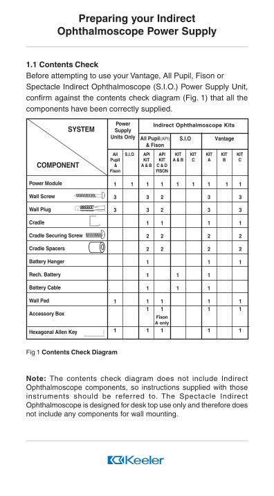
1.1 Contents CheckBefore attempting to use your Vantage, All Pupil, Fison orSpectacle Indirect Ophthalmoscope (S.I.O.) Power Supply Unit,confirm against the contents check diagram (Fig. 1) that all thecomponents have been correctly supplied.
Fig 1 Contents Check Diagram
Note: The contents check diagram does not include IndirectOphthalmoscope components, so instructions supplied with thoseinstruments should be referred to. The Spectacle IndirectOphthalmoscope is designed for desk top use only and therefore doesnot include any components for wall mounting.
COMPONENT
SYSTEMPowerSupply
Units Only
APIKIT
A & B
APIKIT
C & DFISON
KITA & B
KITC
KITA
KITC
KITB
S.I.O Vantage
Indirect Ophthalmoscope Kits
S.I.OAllPupil
&Fison
All Pupil(API)& Fison
FisonA only
1 1 1 1 1 1 1 1 1
3 3 2 3 3
3 3 2 3 3
1 1 1 1
2 2 2 2
2 2 2 2
1 1 1
1 1 1
1 1 1
1 1 1 1 11 1 1 1
1 1 1 1 1
Power Module
Wall Screw
Wall Plug
Cradle
Cradle Securing Screw
Cradle Spacers
Battery Hanger
Rech. Battery
Battery Cable
Wall Pad
Accessory Box
Hexagonal Allen Key
Preparing your IndirectOphthalmoscope Power Supply

1.2 Electrical CheckBefore connecting the power unit to the electricity supply,check that the input voltage on the data rating label corre-sponds with that of your local supply voltage. For full electri-cal information and circuit diagrams, refer to Section 5 - Tech-nical Specification.
1.3 Fitting Instructions for Desk-Top UseKeeler Indirect Ophthalmoscope Power Supply systems aresupplied ready assembled for desk-top use. Place the unitin the desired position and plug the power module into a suit-able power outlet/wall socket. Your power supply unit is nowready to accept Keeler Indirect Ophthalmoscopes. Refer tosection 2 - Standard Operating Instructions.
1.4 Fitting Instructions for In Case UseKeeler Indirect Ophthalmoscopes may be operated directfrom the case for short periods by plugging the power mod-ule into a suitable nearby power outlet/wall socket.
CAUTIONCare should be taken not to close the case lid when theinstrument is being used in this way as this may causedamage to the connecting cables.Alternatively, the Indirect Ophthalmoscope Power Supply maybe removed from the case and operated from the desk orwall mounted (see 2.1)
1.5 Fitting Instructions for Wall Mounted SystemsImportant Notice: Keeler Indirect Ophthalmoscope PowerSupplies are designed to be fitted to all walls. The wall fit-tings supplied are suitable for mounting your power supplyto walls constructed of sound brick, breeze block, concrete
Preparing your IndirectOphthalmoscope Power Supply

or plasterboard. If required alternative fittings suitablefor mounting your power supply on walls constructed frommaterials other than those mentioned above should be ob-tained. If in doubt, consult a qualified builder for advice.Keeler Limited cannot accept any responsibility for anydamage or injury sustained by incorrect assembly, wallmounting or use of wall mounted power supplies.
The Keeler transformer unit must be disconnected from thepower supply before commencing to wall mount the unit.
a) To wall mount your Keeler Power Supply, select a convenientposition on the wall ensuring that there is a suitable poweroutlet/wall socket for the plug-in power module within reachof the interconnecting cord. Also, make sure that there areno water or gas pipes or electrical cables buried in the wall.
b) Refer to the chart over the page (Fig.2) and identify yourpower supply unit. Remove the module(s) shown from the ‘L’shaped rail to expose the wall mounting fixing holes. Thiscanbe done by first removing the plastic screw hole coversand unscrewing the retaining screws using the hex-agonal Allen key provided. Keep the retaining screws safefor later reassembly.
Preparing your IndirectOphthalmoscope Power Supply
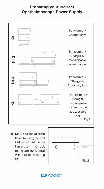
Fig 3
Transformer /Charger only
Transformer /Charger &
rechargeablebattery hanger
Transformer / Charger &
Accessory box
Transformer /Charger,
rechargeablebattery hanger& accessory
box
Kit
4K
it 3
Kit
2K
it 1
Fig 2
c) Mark position of fixingholes by using the wallrail supplied as atemplate. Checkmarks are horizontalwith a spirit level. (Fig3)
Preparing your IndirectOphthalmoscope Power Supply

d) Dr il l holes to aminimum depth of50mm (2") with a6mm (¼") diametermasonry drill. (Fig 4)
Always wear eye protection when
using a drill.
e) The wall plugsprovided are suitablefor solid or p l as te r -board walls. Push orlightly tap the plugsuntil they are flushwith the wall (Fig 5).
f) Screw wall railsecurely to wall usingscrews provided.(Fig 6)
g) Reassemble theunit(s) to the wall railwith the screwspreviously removedusing the hexagonalAllen key.
Fig 4
Fig 5
Preparing your IndirectOphthalmoscope Power Supply
Fig 6

Fig 7
h) Replace the plastic screw holecovers under the wall rail.
i) Secure the cradle to the powerunit using the screws andspacers provided. (Fig 7)
j) The power module for FisonOphthalmoscopes and in somemarkets for the All-Pupil andVantage Ophthalmoscopesmay also be fitted to the wall.Follow the instructions insection 1.5and secure the unitwith the mounting tag. (Fig 8)
k) Place the Indirect Ophthalmo-scope onto the cradle and stickthe wall pad provided below the power unit, to protect theoptics from knockingagainst the wall.
l) If you have a rechargeablebattery pack hanger then placeyour battery onto the hangerusing the belt clip to the rear ofthe battery pack. (Fig.9)
m) The power system is now readyto use. Refer to section 2 -Standard Operating Instruc-
Fig 9
Fig 8
Preparing your IndirectOphthalmoscope Power Supply
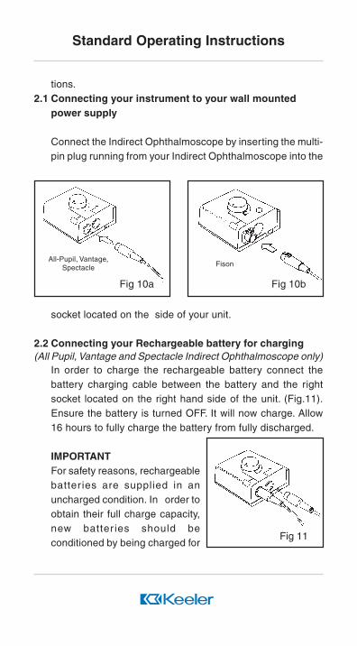
Fig 11
tions.2.1 Connecting your instrument to your wall mounted
power supply
Connect the Indirect Ophthalmoscope by inserting the multi-pin plug running from your Indirect Ophthalmoscope into the
socket located on the side of your unit.
2.2 Connecting your Rechargeable battery for charging(All Pupil, Vantage and Spectacle Indirect Ophthalmoscope only)
In order to charge the rechargeable battery connect thebattery charging cable between the battery and the rightsocket located on the right hand side of the unit. (Fig.11).Ensure the battery is turned OFF. It will now charge. Allow16 hours to fully charge the battery from fully discharged.
IMPORTANTFor safety reasons, rechargeablebatter ies are supplied in anuncharged condition. In order toobtain their full charge capacity,new batter ies should beconditioned by being charged for
Standard Operating Instructions
All-Pupil, Vantage,Spectacle
Fig 10a
Fison
Fig 10b

a continuous period of 24 hours.The full charge capacity will be obtained after 3 or 4 fullcharge/discharge cycles. This should also be carried outwhen batteries have been stored for long periods in a fullydischarged state. After repeated charge/discharge cycles itis possible for a reduction in battery capacity to become ap-parent. The normal capacity can be restored by a period ofextended charge (24 hours) as described for new batteriesabove.
2.3 Connecting your rechargeable battery for useThe Power Supply is designed to charge the KeelerPorta-Power 1.2Ah. 6V Ni Cad battery pack; and shouldnever be used with Non-Rechargeable batteries.To use your battery pack unplug the charging cable at thebattery end. Unplug the Indirect Ophthalmoscope from thepower unit and plug it into the battery. (Fig 12) A fully chargedbattery will provide approximately 40 minutes of full illumi-nation. Longer periods of use may be expected if the powerand illumination are reduced.
2.4 Usage Guide
a) Desk-top or CaseSystemTurning the illuminationcontrol on the top of thepower supply clockwiseswitches the system on,i l luminates the l ightemitting diode (LED),and then controls thebrightness of the instru-
Fig 12
Standard Operating Instructions
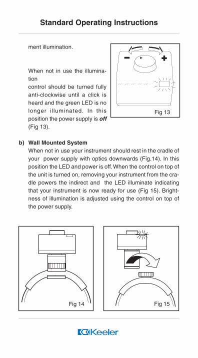
ment illumination.
When not in use the illumina-tioncontrol should be turned fullyanti-clockwise until a click isheard and the green LED is nolonger i l luminated. In thisposition the power supply is off(Fig 13).
b) Wall Mounted SystemWhen not in use your instrument should rest in the cradle ofyour power supply with optics downwards (Fig.14). In thisposition the LED and power is off. When the control on top ofthe unit is turned on, removing your instrument from the cra-dle powers the indirect and the LED illuminate indicatingthat your instrument is now ready for use (Fig 15). Bright-ness of illumination is adjusted using the control on top ofthe power supply.
Fig 13
Fig 15Fig 14
Standard Operating Instructions

Leaving the illumination on for long periods when not in usereduces the remaining life of the Halogen Bulb in your
instrument. We therefore recommend returning the indirectto its cradle or switching off at the control when not in use.
3.1 Cleaning
Should cleaning be required, disconnect the equipment fromthe electricity supply and wipe over with a soft, dry cloth.Do not use solvents for any cleaning purposes since thesemay cause damage.
CAUTIONNever immerse the Indirect Ophthalmoscope Power
Supply unit in water or any other cleaning fluid.
If any part of the Indirect Ophthalmoscope Power Supplyshould become contaminated with biological agents, pleasecontact Keeler Ltd direct for advice on decontaminationprocedures.
3.2 Maintenance
Routine maintenance is limited to visual inspection of thepower module enclosure and interconnecting cables. Shouldany damage be observed to the enclosure of the plug-inpower module or the supply cord of the Fison transformer,discontinue use of the power supply and contact your near-est authorised Keeler Distributor. Interconnecting cablesare not replaceable by the purchaser and where repair isrequired the complete power supply should be returned tothe place of purchase.
Servicing
There are no user-serviceable parts within the Indirect
Ophthalmoscope Power Supply.
Care and Maintenance

GeneralThe Indirect Ophthalmoscope Power Supply units are classII, double insulated devices and are classified as Type Bequipment in accordance with the degree of protection againstelectric shock.
Conditions of Use Temperature :10oC (50oF) to 40oC
(104oF)
Relative Humidity : 30% to 75%
Conditions of Temperature :-20oC (-4oF) to 70oC
(158oF)
Storage
Relative Humidity : 10% to 100%
Note:
It is recommended that the Porta Power C should not be storedat temperatures below 0oC (32oF)
Fison Transformer (and Vantage/All-Pupil in some regions)
Power Module Dimensions 103 x 77 x 70mm (4.0 x 3.0 x 2.8
inches) Control Unit Dimensions 96.5 x 89 x 54mm (3.8 x 3.5
x 2.1 inches)
Length of Power 2m (6.6 ft)Supply Cord
Length of 3m (9.8 ft)Interconnecting Cord
Weight (Total) 1.415 kg (3.1 lb)
Input Voltage 100, 120, 220-240V
See rating plate for the nominal input voltage applicable to the
particular transformer.
Input frequency 100V unit; 50/60 Hz
Technical Specifications
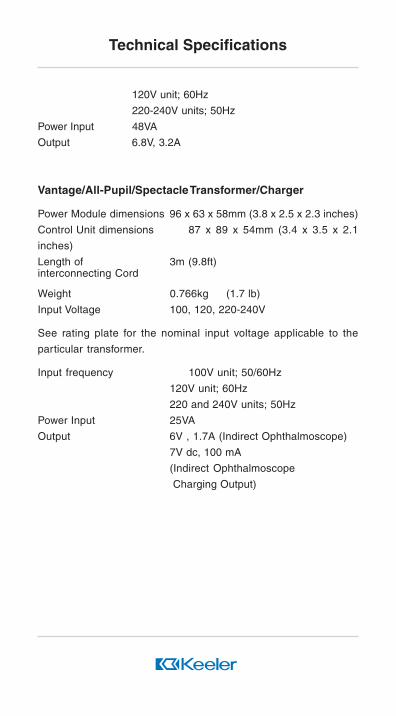
120V unit; 60Hz
220-240V units; 50Hz
Power Input 48VA
Output 6.8V, 3.2A
Vantage/All-Pupil/Spectacle Transformer/Charger
Power Module dimensions 96 x 63 x 58mm (3.8 x 2.5 x 2.3 inches)
Control Unit dimensions 87 x 89 x 54mm (3.4 x 3.5 x 2.1
inches)
Length of 3m (9.8ft)interconnecting Cord
Weight 0.766kg (1.7 lb)
Input Voltage 100, 120, 220-240V
See rating plate for the nominal input voltage applicable to the
particular transformer.
Input frequency 100V unit; 50/60Hz
120V unit; 60Hz
220 and 240V units; 50Hz
Power Input 25VA
Output 6V , 1.7A (Indirect Ophthalmoscope)
7V dc, 100 mA
(Indirect Ophthalmoscope
Charging Output)
Technical Specifications

Fig 16Circuit Diagram for all pupil /
Spectacle Indirect Power Supply
Technical Specifications

Fig 17Circuit Diagram for Fison Indirect Power Supply
Technical Specifications

All Indirect Ophthalmoscope Power Supplies have been designedto make upgrading simple and convenient. Check Fig 18 for theupgrade options available and how to order. For any upgrade optionnot illustrated please refer to your nearest authorised dealer or Keelerdirect.
To upgrade your power supply, follow the arrow upwards from existingunit to desired enhancement level and note numbers alongside. Referto list below for parts required.
1
2
3
1999-P-1002 Accessory Box Kit
1999-P-7113 Cradle Kit
1999-P-7121 Battery Hanger
4
5
6
7
8
9
1999-P-7279 Accessory Box Ext.Kit
1952-P-5030 Charging Cord Set
1999-P-1133 Wall Fixing Kit
1999-P-7199 Rail Kit - W6
1999-P-7252 Hanger Ext. Kit
1999-P-7260 Hanger &Accessory Box Kit.Ext
Basic unitfor desk use
Wall mounted unit
Desk unit & Accessory box
Wall mounted unitwith hanger(not Fison)
Wall mountedunit with hanger
Fig 18
Upgrading your IndirectOphthalmoscope Power Supply
Wall mountedunit with
accessory boxand hanger
When ordering a rechargeable battery for desk& wall units with hangers, item 8 must also beordered. (API ,SIO & Vantage)

EP59-06400 ISSUE A DTP ref: (superceed 93-15) 96-13
Cybernetic
The CE mark on this product indicates it has been tested to and conforms with the provisions noted within the 93/42/eec Medical Device Directive.
Cybernetic
MANUFACTURED BY: Keeler Limited Clewer Hill Road Windsor Berks SL4 4AA Tel: +44 (0) 1753 857 177 Fax: +44 (0) 1753 857 817 DISTRIBUTED BY: Keeler Instruments Inc. 456 Parkway Broomall PA 19008 USA Toll Free: 1 800 523 5620 Tel: 610 353 4350 Fax: 610 353 7814 As part of our policy of continued product development we reserve the right to alter and/or amend specifications at any time without prior notice.